TTDM Operation and Maintenance Manual - California Detection ...
TTDM Operation and Maintenance Manual - California Detection ...
TTDM Operation and Maintenance Manual - California Detection ...

You also want an ePaper? Increase the reach of your titles
YUMPU automatically turns print PDFs into web optimized ePapers that Google loves.
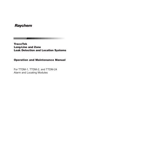
R<br />
TraceTek<br />
Long-Line <strong>and</strong> Zone<br />
Leak <strong>Detection</strong> <strong>and</strong> Location Systems<br />
<strong>Operation</strong> <strong>and</strong> <strong>Maintenance</strong> <strong>Manual</strong><br />
For <strong>TTDM</strong>-1, <strong>TTDM</strong>-2, <strong>and</strong> <strong>TTDM</strong>-24<br />
Alarm <strong>and</strong> Locating Modules
A<br />
Identifying <strong>TTDM</strong> Features<br />
1<br />
R<br />
TraceTek<br />
<strong>TTDM</strong><br />
External View [A]<br />
(1) LCD display gives up-to-date<br />
information regarding the condition of<br />
the system.<br />
Internal View [B]<br />
(7) User interface board<br />
(8) 4–20 mA board<br />
2<br />
(2) Icons <strong>and</strong> LEDs (light emitting<br />
diodes):<br />
Monitoring LED<br />
green<br />
(9) Sensor interface board<br />
(10) Motherboard<br />
Test<br />
3 4 5<br />
Reset<br />
Service (Required) LED<br />
Leak LED<br />
yellow<br />
red<br />
(11) Power supply board<br />
Fault LED<br />
red<br />
(12) Fuse (200 mA, 250 V)<br />
6<br />
Menu<br />
(3) (Self) Test key<br />
(13) Power cable terminal block<br />
B<br />
7<br />
Esc<br />
Enter<br />
8 9<br />
10<br />
Can be used at any time to<br />
verify the correct operation of the<br />
module. The module performs a<br />
series of self-diagnostic checks.<br />
(4) Silence key<br />
Used to silence audible alarms<br />
(14) Ground (earth) stud<br />
(15) Fault relay cable plug <strong>and</strong> socket<br />
(16) Leak relay cable plug <strong>and</strong> socket<br />
(17) Service relay cable plug <strong>and</strong> socket<br />
11<br />
(5) Reset key<br />
Used to reset the leak alarm relay<br />
after a leak has been cleared.<br />
(18) 4–20 mA port plug <strong>and</strong> socket<br />
(19) RS-232/485 port plug <strong>and</strong> socket<br />
24<br />
23<br />
12<br />
13<br />
(6) Menu keys<br />
The menu button provides access to<br />
various features that may be viewed<br />
<strong>and</strong>/or edited. The menus are navigated<br />
with the arrow keys together with the<br />
Esc (escape) <strong>and</strong> Enter keys.<br />
(20) Sensing cable plug <strong>and</strong> socket<br />
(21) Reserved for future use<br />
(22) Ribbon cable<br />
14<br />
(23) Volume adjustment<br />
(24) LCD contrast adjustment<br />
22 21<br />
20<br />
19<br />
18<br />
17<br />
16<br />
15<br />
i<br />
ii
Introduction<br />
Contents<br />
Please read before use<br />
Please read these instructions carefully <strong>and</strong> keep in a safe place (preferably close to the<br />
module) for future reference.<br />
The instructions provided in this booklet must be followed carefully to ensure proper<br />
operation. If the equipment is used in a manner not specified by the manufacturer, the<br />
protection provided by the equipment may be impaired.<br />
Description<br />
The <strong>TTDM</strong> module has been specifically designed for use with TraceTek sensing cables<br />
(all TT1000, TT3000, <strong>and</strong> TT5000 series sensing cables, <strong>and</strong> all TT100, TT300, <strong>and</strong> TT500<br />
series long-line sensing cables). <strong>TTDM</strong> can monitor up to 5000 ft (1500 m) of sensing<br />
cable <strong>and</strong> can detect <strong>and</strong> locate the presence of liquid at any point along the cable. The<br />
module also monitors the system for other alarm conditions:<br />
• Service required<br />
• Fault<br />
Each “event” (service, leak, or fault) is recorded in an Events History with the time <strong>and</strong><br />
date of occurrence. This allows easy tracking of events.<br />
Preparation<br />
Before operation, the instructions in the “<strong>TTDM</strong> Installation Instructions” that accompany<br />
the system must be followed so that the module is properly:<br />
• Mounted<br />
• Powered (wired <strong>and</strong> energized)<br />
• Connected to a TraceTek sensing cable with a TraceTek jumper or leader cable<br />
• Commissioned (a completed commissioning form should be supplied)<br />
If these steps have not been taken, please refer to the “<strong>TTDM</strong> Installation Instructions” in<br />
order to complete the installation.<br />
In addition, there should be a system map, which indicates the sensing cable layout with<br />
reference l<strong>and</strong>marks throughout the system.<br />
Notes<br />
• Throughout this manual, the examples shown use distances in feet.<br />
Identifying <strong>TTDM</strong> Features . . . . . . . . . . . . . . . . . . . . . . . . . . . . . . . . . . . . . . . . . . . . . . .ii<br />
Introduction . . . . . . . . . . . . . . . . . . . . . . . . . . . . . . . . . . . . . . . . . . . . . . . . . . . . . . . . .iii<br />
Leak <strong>Detection</strong> System Description . . . . . . . . . . . . . . . . . . . . . . . . . . . . . . . . . . . . . . . .2<br />
Connection to Other Devices . . . . . . . . . . . . . . . . . . . . . . . . . . . . . . . . . . . . . . . . . . . . .4<br />
The Basic Events . . . . . . . . . . . . . . . . . . . . . . . . . . . . . . . . . . . . . . . . . . . . . . . . . . . . . .6<br />
Leak <strong>Detection</strong> <strong>and</strong> Location Events . . . . . . . . . . . . . . . . . . . . . . . . . . . . . . . . . . . . . . . .8<br />
Service Events . . . . . . . . . . . . . . . . . . . . . . . . . . . . . . . . . . . . . . . . . . . . . . . . . . . . . . .10<br />
Fault Events . . . . . . . . . . . . . . . . . . . . . . . . . . . . . . . . . . . . . . . . . . . . . . . . . . . . . . . .12<br />
Multiple Events . . . . . . . . . . . . . . . . . . . . . . . . . . . . . . . . . . . . . . . . . . . . . . . . . . . . . .14<br />
Navigating the Menu Structure . . . . . . . . . . . . . . . . . . . . . . . . . . . . . . . . . . . . . . . . . .18<br />
The Events History Log . . . . . . . . . . . . . . . . . . . . . . . . . . . . . . . . . . . . . . . . . . . . . . . .19<br />
Diagnostics (System Status) . . . . . . . . . . . . . . . . . . . . . . . . . . . . . . . . . . . . . . . . . . . .20<br />
Changing Settings (View/Edit Settings) . . . . . . . . . . . . . . . . . . . . . . . . . . . . . . . . . . . .22<br />
Appendix 1 - Menu Structure . . . . . . . . . . . . . . . . . . . . . . . . . . . . . . . . . . . . . . . . . . . .25<br />
Appendix 2 - Events Glossary . . . . . . . . . . . . . . . . . . . . . . . . . . . . . . . . . . . . . . . . . . .26<br />
Appendix 3 - <strong>Maintenance</strong> . . . . . . . . . . . . . . . . . . . . . . . . . . . . . . . . . . . . . . . . . . . . . .28<br />
Appendix 4 - Interface Details . . . . . . . . . . . . . . . . . . . . . . . . . . . . . . . . . . . . . . . . . . .30<br />
Appendix 5 - Wiring Details . . . . . . . . . . . . . . . . . . . . . . . . . . . . . . . . . . . . . . . . . . . . .32<br />
Appendix 6 - TraceTek Technical Data . . . . . . . . . . . . . . . . . . . . . . . . . . . . . . . . . . . . . .33<br />
• Later versions of software may provide new features <strong>and</strong> change certain other details.<br />
This manual documents UI Version 1.05.<br />
iii<br />
1
R<br />
POWER<br />
ON<br />
Test<br />
Test<br />
Esc<br />
ZONE 1<br />
ON<br />
Reset<br />
Menu<br />
ZONE 2<br />
ON<br />
PROTRAC2<br />
ALARM<br />
Mode<br />
Enter<br />
//////////////////////////////////////////////////////////////////////////////////////////////////////////////////<br />
/<br />
/<br />
/<br />
/<br />
/<br />
/<br />
/<br />
/<br />
/<br />
/<br />
/<br />
/<br />
/<br />
/<br />
/<br />
/<br />
/<br />
R<br />
POWER<br />
ON<br />
Test<br />
Test<br />
Esc<br />
ZONE 1<br />
ON<br />
Reset<br />
Menu<br />
ZONE 2<br />
ON<br />
PROTRAC2<br />
ALARM<br />
Mode<br />
Enter<br />
/<br />
/<br />
/<br />
/<br />
/<br />
/<br />
/<br />
/<br />
/<br />
/<br />
/<br />
/<br />
/<br />
/<br />
/<br />
/<br />
/<br />
/<br />
/<br />
/<br />
/<br />
/<br />
/<br />
/<br />
/<br />
/<br />
/<br />
/<br />
/<br />
/<br />
/<br />
/<br />
/<br />
/<br />
/<br />
/<br />
/<br />
/<br />
/<br />
/<br />
/<br />
/<br />
/<br />
/<br />
/<br />
/<br />
/<br />
/<br />
/<br />
/<br />
/<br />
/<br />
/<br />
/<br />
/<br />
/<br />
/<br />
/<br />
/<br />
/<br />
/<br />
/<br />
/<br />
/<br />
/<br />
/<br />
/<br />
/<br />
/<br />
/<br />
/<br />
/<br />
/<br />
/<br />
/<br />
/<br />
/<br />
/<br />
/<br />
/<br />
/<br />
/<br />
/<br />
/<br />
/<br />
/<br />
/<br />
/<br />
/<br />
/<br />
Leak <strong>Detection</strong> System Description<br />
TraceTek Longline System<br />
A TraceTek longline system provides distributed leak detection <strong>and</strong> location to monitor<br />
long lengths <strong>and</strong> wide areas. The system consists of the <strong>TTDM</strong> Alarm <strong>and</strong> Locating<br />
Module <strong>and</strong> up to 5000 ft (1500 m) of sensing cable.<br />
The sensing cable detects liquid at any point along its length. The module then signals the<br />
alarm <strong>and</strong> displays the distance to the leak.<br />
The longline system includes sensing cable <strong>and</strong> circuit components (leader cable, jumper<br />
cables, end terminations, weighted lengths, <strong>and</strong> branching connectors) with connectors<br />
that allow components of the system to plug together.<br />
<strong>TTDM</strong><br />
Alarm <strong>and</strong><br />
Locating Module<br />
Modular<br />
leader cable<br />
Jumper<br />
cable<br />
/ //////////////////////////////////////////////////////////////////////////////////////////////////////////////////////////////////<br />
End<br />
termination<br />
Sensing<br />
cable<br />
Sensing<br />
cable<br />
Modular end<br />
termination<br />
//////////////////////////////////////////////////////////////////////////////////<br />
Modular<br />
branching<br />
connector<br />
Sensing<br />
cable<br />
Jumper<br />
cable<br />
/<br />
/<br />
/<br />
/<br />
/<br />
/<br />
/ //////////////////////////////////////////////////////////////////////////////////////////////////////////////////////////////////////////////////////<br />
Weighted<br />
length<br />
/<br />
/<br />
The TraceTek Zone System<br />
The TraceTek zone system is a leak detection <strong>and</strong> location system that monitors many<br />
separate locations from one point. The zone system consists of the <strong>TTDM</strong> Alarm <strong>and</strong><br />
Locating Module <strong>and</strong> up to 100 separate sensing zones interconnected by one run of<br />
jumper cable.<br />
Each sensing zone consists of a zone connector <strong>and</strong> one 5 ft (1.5 m) length of sensing<br />
cable. If liquid is detected, the module signals the alarm <strong>and</strong> displays the zone where the<br />
leak has occurred. The zones are numbered sequentially by the system electronics.<br />
Important: In a TraceTek zone system, only zone sensing cables (TT3000 zone or<br />
TT5000-series zone) may be used. Each sensing cable plugs into a zone connector.<br />
The last zone connector must have an end termination.<br />
Modular<br />
leader<br />
cable<br />
<strong>TTDM</strong><br />
Alarm <strong>and</strong><br />
Locating Module<br />
/ ////////////////////////////////////////<br />
/<br />
/<br />
/<br />
/<br />
/<br />
/<br />
/<br />
/<br />
/ /////////////////////////////////<br />
/<br />
/<br />
/<br />
/<br />
/<br />
/<br />
/<br />
/////////////////////////////////////////////<br />
Jumper<br />
cable<br />
/ ////////////////////////////////////////<br />
/<br />
/<br />
/<br />
/<br />
/<br />
/<br />
/<br />
/<br />
/ /////////////////////////////////<br />
/<br />
/<br />
/<br />
/<br />
/<br />
/<br />
/<br />
/////////////////////////////////////////////<br />
/ ////////////////////////////////////////<br />
/<br />
/<br />
/<br />
/<br />
/<br />
/<br />
/<br />
/<br />
/ /////////////////////////////////<br />
/<br />
/<br />
/<br />
/<br />
Zone<br />
connector<br />
/<br />
/<br />
/<br />
/////////////////////////////////////////////<br />
End<br />
termination<br />
Zone<br />
sensing<br />
cable<br />
The weighted length resistor simulates a 15 ft (5 m) length of sensing cable. Installed at<br />
the boundary between two areas, it allows the user to clearly identify the area where the<br />
leak has occurred.<br />
The branching connector enables the sensing cable to be branched. An end termination<br />
completes each branch. At the branching connector, the system first counts the sensing<br />
cable along the branch (middle connector), before it continues with the main run. Two<br />
built-in 15 ft (5 m) weighted length resistors allow the user to clearly identify on which<br />
leg a leak has occurred near the branching connector.<br />
An important part of the TraceTek longline system is the system map, a sensing cable<br />
layout plan with actual distance readings. Thus, in case of an alarm, the location of the event<br />
can be determined quickly. The map should be placed near the Alarm <strong>and</strong> Locating Module.<br />
2 3
Connection to Other Devices<br />
Relays<br />
<strong>TTDM</strong> has three relays:<br />
• Service<br />
• Leak<br />
• Fault<br />
Each relay provides two Form-C relay contacts, with normally open <strong>and</strong> normally closed<br />
contacts both provided. The relays are de-energized to indicate an alarm condition. The<br />
diagram below shows the relay status when each is in an alarm (de-energized) state.<br />
SERVICE RELAY LEAK RELAY FAULT RELAY<br />
15 16 17 18 19 20 21 22 23 24 25 26 27 28 29 30 31 32<br />
(For other connection options, please consult Appendix 5 - Wiring Details.)<br />
4–20 mA<br />
The module is equipped with an analog 4–20 mA interface. The <strong>TTDM</strong> adjusts its current<br />
output based on whether an alarm condition exists, <strong>and</strong> (when a leak is detected) the<br />
location of the leak. Its output can be scaled to make full use of the 4–20 mA range for<br />
the length of sensing cable connected.<br />
Serial Port<br />
The <strong>TTDM</strong> module has a serial port (marked EXT COM PORT) that can be configured for<br />
use either as an RS-232 or RS-485 transceiver. The factory default is RS-232, <strong>and</strong> is<br />
suitable for connecting the <strong>TTDM</strong> to single devices up to 50 ft (15 m) away. The st<strong>and</strong>ard<br />
configuration is RS-232 full-duplex with no hardware h<strong>and</strong>shaking, which is suitable for<br />
connection to many devices (such as a remote host PC, laptop, or modem).<br />
The RS-232/485 port (19 on foldout) is connector J13 on the <strong>TTDM</strong> motherboard. The<br />
pinouts for connector J13 on the <strong>TTDM</strong> motherboard are listed below, with functions for<br />
RS-232 usage noted.<br />
Pin Desc. Use<br />
J13-5 RX/A Receive data<br />
J13-6 TX/B Transmit data<br />
J13-7 RTS Request to send —<br />
for hardware h<strong>and</strong>shaking<br />
J13-8 CTS Clear to send —<br />
for hardware h<strong>and</strong>shaking<br />
J13-9 +5V/DTR +5V supply/DTR if<br />
needed by modem<br />
J13-10 GND Supply return<br />
Note: For further information, see Appendix 4 - Interface Details.<br />
Note: The current transmitter is isolated from the sensing circuitry <strong>and</strong> therefore requires<br />
an external 24 Vdc power supply.<br />
The 4–20 mA output port (18 on foldout) is connector J2 on the <strong>TTDM</strong> motherboard,<br />
with terminals as noted in the following table:<br />
Pin Desc. Use<br />
J2-11 IRTN Current loop return<br />
J2-12 IOUT Current output<br />
J2-13 +V 24 Vdc supply (required)<br />
J2-14 +VRTN 24 Vdc common (required)<br />
Note: More information about operation <strong>and</strong> testing is found in Appendix 4 -<br />
Interface Details.<br />
4 5
The Basic Events<br />
The Icons<br />
The Icons (2 on foldout) represent the four main states of the <strong>TTDM</strong> module:<br />
Leak<br />
Monitoring<br />
Service<br />
Leak<br />
Fault<br />
Monitoring<br />
Green Yellow Red Red<br />
When liquid is detected on the sensing cable, this red Leak LED illuminates. Note that the<br />
green LED remains illuminated; the unit continues to monitor for leaks <strong>and</strong> spills. This is covered<br />
more fully in the following section “Leak <strong>Detection</strong> <strong>and</strong> Location Events”, on page 8.<br />
Fault<br />
When the <strong>TTDM</strong> module detects a fault—either a cable fault, or an electronics fault—it<br />
lights this red LED. Note that in a Fault condition, the <strong>TTDM</strong> module is unable to detect a<br />
leak. For further information, see the “Fault Events” section on page 12.<br />
This green LED indicates that the <strong>TTDM</strong> is monitoring the sensing cable. If something<br />
happens that makes it impossible for the <strong>TTDM</strong> to monitor the sensing cable (for example,<br />
the cable is broken), the Monitoring LED will extinguish.<br />
Service<br />
LCD Display<br />
Leak 10 ft<br />
Leak Cleared<br />
Press Reset<br />
16:30 14-Feb-1996<br />
Line 1 indicates the original location of a leak.<br />
Line 2 indicates the present status (except when a leak is initially detected, since the initial<br />
location is always shown on line 1).<br />
The <strong>TTDM</strong> is able to give advance warning of potential problems. This yellow Service LED<br />
illuminates to indicate that service is required. Note that the green LED remains illuminated;<br />
the unit continues to monitor for leaks during a Service alarm.<br />
See the “Service Events” section on page 10 for further details.<br />
Line 3 may advise action or provide special instructions.<br />
Line 4 displays the current time <strong>and</strong> date (the colon blinks once a second). To highlight<br />
the present status, the line of the display with the most recent event flashes.<br />
Hint: The LCD contrast may be adjusted (24 on foldout).<br />
6 7
Leak <strong>Detection</strong> <strong>and</strong> Location Events<br />
If the <strong>TTDM</strong> unit has been installed correctly, <strong>and</strong> the system is clear, the LCD display will<br />
appear as follows:<br />
System Normal<br />
15:53 14-Feb-1996<br />
To Locate the Leak<br />
Using the number displayed by the <strong>TTDM</strong>, refer to the system map <strong>and</strong> determine where<br />
the leak was detected.<br />
To Clear the System<br />
Fix the leak <strong>and</strong> cleanup the area affected. Then dry the sensing cable (in the case of<br />
TT1000 <strong>and</strong> TT3000) or replace the tripped section (TT5000 family).<br />
Once the sensing cable is clear, the module responds <strong>and</strong> the display changes:<br />
Leak<br />
When liquid is detected, the following occur:<br />
• The audible alarm sounds.<br />
• The red Leak LED illuminates.<br />
• The interfaces (relays, 4–20 mA, serial port) respond.<br />
• The display changes to show the location of the leak:<br />
Leak 10 ft<br />
16:00 14-Feb-1996<br />
Leak 10 ft<br />
Leak Cleared<br />
Press Reset<br />
16:30 14-Feb-1996<br />
Notice that the red LED remains on. This is to indicate that the leak relay is still in the alarm state.<br />
To Reset the Leak Relay<br />
In order to reset the leak relay <strong>and</strong> return the module to the “System Normal” state, press<br />
the reset button. Before doing so, check that any external or remote equipment controlled<br />
by the <strong>TTDM</strong> is ready to be reset.<br />
Hint: If manual reset is not required, the module can be set to auto-reset<br />
(see “Auto-Reset” under “Leak Settings” on page 23).<br />
The following actions should be taken:<br />
• Silence the alarm.<br />
• Locate the leak.<br />
• Clear the system.<br />
• Reset the leak relay.<br />
Once the Reset button is pressed, the relay returns to normal, the red Leak LED<br />
extinguishes, <strong>and</strong> the LCD display changes:<br />
System Normal<br />
16:53 14-Feb-1996<br />
To Silence the Alarm<br />
Press the Silence key to silence the audible alarm.<br />
Hint: If audible alarms are not required, the module can be set to disable them (see<br />
“Audible Alarm” under “Leak Settings” on page 23).<br />
8 9
Service Events<br />
Introduction<br />
A TraceTek sensing circuit consists of two electrical loops (a diagram of the sensing<br />
circuit is shown in Appendix 6). The <strong>TTDM</strong> module constantly monitors to see whether<br />
current is passing between the loops. When the system is normal, there is no current<br />
passing between the loops. When there is a leak on the system, the maximum current<br />
flows (just 270 µA; the sensing cable operates on low voltage <strong>and</strong> is safe to touch).<br />
If, however, the <strong>TTDM</strong> module detects a lower but significant level of current flow<br />
between the loops, it activates the Service alarm.<br />
A low-level current could indicate one or more of the following:<br />
• A very small leak (which may soon develop into a full leak alarm).<br />
• Heavy condensation or small spills (coffee, tea, etc.) on a water-sensing or aqueouschemical-sensing<br />
cable (TT1000 <strong>and</strong> TT3000).<br />
• Conductive material on a water-sensing or aqueous-chemical-sensing cable. The<br />
material might be metal filings, concrete dust, flux, mastic, or other construction<br />
debris, or carbon-based dust from air-h<strong>and</strong>ling units, printers, or copiers.<br />
While it is recommended that service alarms be investigated, the operation of the system<br />
is not threatened; the <strong>TTDM</strong> will continue to detect leaks. However, the accuracy of location<br />
may be affected in certain cases.<br />
The Service Alarm<br />
When a condition requiring service (such as described above) is detected, the following<br />
occur:<br />
• An intermittent beep sounds.<br />
• The yellow Service LED illuminates.<br />
• The service relay goes to alarm condition.<br />
• The LCD display changes to the following:<br />
The number in square brackets indicates the estimated location of the material causing<br />
the alarm. The number is shown with square brackets to indicate that the value is only an<br />
estimate.<br />
Hint: Because the cause (concrete dust for example) of low-level current may be distributed<br />
over several feet/meters of cable, it is not always possible for the <strong>TTDM</strong> to return an<br />
accurate location. However, the indicated location is always a good point from which to<br />
begin a troubleshooting procedure.<br />
The following actions should be taken:<br />
• Silence the audible alarm.<br />
• Clear the cable.<br />
To Silence the Audible Alarm<br />
Press the Silence key to silence the alarm.<br />
To Clear the Cable<br />
Investigate the cause of the alarm <strong>and</strong> conduct cleanup or maintenance accordingly.<br />
Hint: If material causing a service alarm is spread throughout the system, it is often<br />
useful to subdivide the system; see Appendix 3 - <strong>Maintenance</strong>, for further information.<br />
When the material (such as moisture or concrete dust) or conditions causing the alarm<br />
are removed, the yellow LED goes out, <strong>and</strong> the service relay returns to its normal state:<br />
System Normal<br />
16:57 14-Feb-1996<br />
Service Req’d [11]<br />
15:53 14-Feb-1996<br />
10 11
Fault Events<br />
Introduction<br />
Several conditions could lead to a fault alarm:<br />
• A cable is disconnected.<br />
• A cable is damaged.<br />
• A connection is damaged.<br />
• There is a problem with the module.<br />
What the Module Does<br />
The following shows how the alarm display would appear if the fault were caused by a<br />
broken or disconnected cable. (The <strong>TTDM</strong> would display a different message for a different<br />
type of fault, such as a loss of continuity in only one of the sensing loops):<br />
To Remedy the Problem<br />
Find the problem <strong>and</strong> rectify. This may mean reconnecting the cable, or finding the damaged<br />
section <strong>and</strong> replacing it. If the cause of the fault is not obvious by visual inspection,<br />
it is often useful to subdivide the system <strong>and</strong> test individual sections with a TraceTek<br />
Portable Test Box.<br />
As soon as the fault is rectified, the relay, LED, <strong>and</strong> LCD screen return to their<br />
normal state:<br />
System Normal<br />
15:53 14-Feb-1996<br />
Cable Break<br />
17:53 14-Feb-1996<br />
When a fault condition is detected, the following occur:<br />
• An audible alarm sounds.<br />
• The green Monitoring LED turns off (no longer able to detect a leak).<br />
• The red Fault LED turns on.<br />
• Interfaces react.<br />
The following actions should be taken:<br />
• Silence the audible alarm.<br />
• Remedy the problem.<br />
To Silence the Audible Alarm<br />
Press the red Silence key to silence the alarm.<br />
12 13
Multiple Events<br />
In addition to storing all events in memory, <strong>TTDM</strong> gives a direct indication of multiple<br />
events, that is, events which happen after an initial leak but before the module is manually<br />
reset.<br />
The first line of the display always indicates where the liquid was first detected.<br />
This location is the most useful in identifying the source of the leak.<br />
The second line displays the most recent event. For example:<br />
Leak 11 ft<br />
Re-Alarm 20 ft<br />
Example (continued):<br />
Before the problem can be dealt with, the leak spreads. Once the module has detected<br />
significant movement (that is, greater than the Re-Alarm distance—see “Re-alarm distance”<br />
on page 23 for more detail), the module goes into alarm once again:<br />
Leak 50 ft<br />
Re-Alarm 55 ft<br />
16:01 14-Feb-1996<br />
15:53 14-Feb-1996<br />
The second line flashes to highlight the present status. If the cable is then disconnected,<br />
the display will change again:<br />
Leak 11 ft<br />
Cable break<br />
15:53 14-Feb-1996<br />
Notice that the first line remains unchanged. The second line changes to reflect the<br />
present condition of the system.<br />
Moving Leak<br />
The <strong>TTDM</strong> continues to monitor during “service” <strong>and</strong> “leak” alarms, ensuring that the<br />
installation is afforded full-time protection.<br />
The <strong>TTDM</strong> will re-alarm when the leak moves more than the re-alarm distance, for which<br />
the default is 5 ft (1.5 m). The audible alarm will sound, the second line of the LCD will<br />
change, <strong>and</strong> a new event will be added to the Events History.<br />
The LCD now displays the FIRST leak <strong>and</strong> the MOST RECENT alarm. The FIRST recorded<br />
leak is likely to be close to the source of the leak.<br />
The MOST RECENT leak shows the current “electrical center” of the liquid (essentially a<br />
weighted average). If the re-alarm number is close to the first (as in the example above),<br />
it is likely that the leak has spread.<br />
Should the leak continue to spread, the <strong>TTDM</strong> would re-alarm again; the second line is<br />
updated again:<br />
Leak 50 ft<br />
Re-Alarm 60 ft<br />
16:23 14-Feb-1996<br />
Example:<br />
Suppose a leak is detected at 50 feet:<br />
Leak 50 ft<br />
15:59 14-Feb-1996<br />
Hint: Use the Events History to track the events between the “first leak” <strong>and</strong> the “most<br />
recent event.” See “The Events History Log” section on page 19.<br />
14 15
Additional Leak<br />
If liquid contacts the sensing cable away from the initial leak, the module will re-alarm. If<br />
the location is distant from the last alarm, the <strong>TTDM</strong> shows a location in square brackets.<br />
Brackets indicate that the value shown requires interpretation; when an additional leak<br />
occurs, the value represents the “electrical center” of the leaks.<br />
Leak 50 ft<br />
Re-Alarm [1045]<br />
15:53 14-Feb-1996<br />
The display also prompts the user to check the Events History log in order to investigate<br />
the sequence of events between the first leak at 50 ft, <strong>and</strong> this re-alarm event.<br />
Note how this leak event differs from the simpler leak event detailed on page 8:<br />
• Rather than displaying the message “Leak 50 ft,” the display puts the location in square<br />
brackets. This indicates that 50 ft is the likely location of the leak.<br />
Case 2 - Service, then leak at same location<br />
If a leak is detected at nearly the same location as that causing a Service Required alarm,<br />
<strong>TTDM</strong> operates differently, as shown below.<br />
First, there is an alarm for Service Required.<br />
Service Req’d[237]<br />
16:53 28-Feb-1996<br />
Service-to-Leak Alarm<br />
Case 1 - Different locations<br />
Although <strong>TTDM</strong> can continue to monitor when a Service Required alarm is in effect, the<br />
accuracy of location may be impaired. <strong>TTDM</strong> indicates this by displaying the leak location<br />
in square brackets.<br />
Example:<br />
Service Req’d[2003]<br />
15:53 14-Feb-1996<br />
Subsequently, a full-fledged leak is detected at nearly the same location. The <strong>TTDM</strong><br />
responds as shown below:<br />
Leak 239 ft<br />
17:45 28-Feb-1996<br />
If a leak contacts the sensing cable before service was performed, the display would<br />
appear as below:<br />
Leak [50]<br />
Since the Service Required alarm was at the same location, it is interpreted as an early<br />
indication of the leak. The <strong>TTDM</strong> therefore clears the service alarm, <strong>and</strong> displays the leak<br />
location without brackets.<br />
15:53 14 Feb 1996<br />
16 17
Navigating the Menu Structure<br />
The Events History Log<br />
Please refer to “Appendix 1 - Menu Structure” on page 25 for an overview of the menu<br />
structure <strong>and</strong> to item 6 on the foldout for the menu keys which are also shown below:<br />
One extremely useful function provided by <strong>TTDM</strong> is the ability to record a series of<br />
events. The <strong>TTDM</strong> module keeps track of a list of 512 events.<br />
For a full list of event types, please refer to “Appendix 2 - Events Glossary” on page 26.<br />
Accessing the Events History Log<br />
• Press Menu.<br />
Menu<br />
• Select Events History (scroll down with the down arrow key).<br />
• Press Enter.<br />
The most recent (that is, current) event is displayed:<br />
Esc<br />
Start by pressing the Menu key.<br />
Use the four arrow keys to scroll through menu items, <strong>and</strong> to select individual characters.<br />
To go one level deeper into the menu structure, press Enter.<br />
To go back one level in the menu structure, Press Esc.<br />
Enter<br />
The Scroll Bar<br />
The scroll bar (see example below) indicates that there is more information off screen; the<br />
arrow indicates the direction of further information:<br />
Events History: ■<br />
* Reset ■<br />
09:01 17-Feb-95 ■<br />
[23 of 23] ▼<br />
The arrow at the bottom right-h<strong>and</strong> corner indicates that there are further events<br />
‘below’ (= before) this one. The bottom line of the display indicates that the unit has<br />
recorded 23 events, <strong>and</strong> the one displayed is the most recent event.<br />
• Press Down Arrow key. The previous event is displayed:<br />
Events History: ▲<br />
Leak Cleared<br />
■<br />
11:33 15-Feb-95 ■<br />
[22 of 23] ▼<br />
View/Edit Settings<br />
General<br />
Leak<br />
Ports<br />
■<br />
■<br />
■<br />
▼<br />
• Press Down Arrow key again. The third from last event is displayed:<br />
Events History: ▲<br />
Leak 250 ft<br />
■<br />
09:01 13-Feb-95 ■<br />
[21 of 23] ▼<br />
Hint: To quickly move to a view of the most recent event, press the Right-Arrow key.<br />
To move to the oldest event, press the Left-Arrow key.<br />
The <strong>TTDM</strong> can store up to 512 events. If 512 events are already stored, the oldest event is<br />
discarded as a new event is registered. When this has occurred, the Events History leaves<br />
the bottom line of the display blank. Contact Raychem for assistance if you wish to clear<br />
the event history.<br />
18 19
Diagnostics (System Status)<br />
System Status<br />
System Status provides a real-time view of the system. You gain access to this feature<br />
through the main menu. When System Status is selected, the <strong>TTDM</strong> displays the following<br />
screen (the “{system status}” entry on the second line is explained below):<br />
System Status: ■<br />
{system status} ■<br />
Test Length 4785 ft■<br />
Location ----- ft▼<br />
The arrow at the bottom right indicates other entries can be accessed with the down<br />
arrow key. The complete list of information available in System Status is shown below:<br />
System Status<br />
{system status}<br />
Test Length 4785 ft<br />
Location ----- ft<br />
Current 0 µA<br />
R S-to-S ----- kΩ<br />
R RG Loop 18658 Ω<br />
R YB Loop 18656 Ω<br />
SI Version 100<br />
UI Version 105<br />
R Loc<br />
0 Ω<br />
SI Status 1024<br />
UI Status 1024<br />
SI Comm 100<br />
“{system status}”<br />
This is a variable field, which can contain any of the following text, depending on the state<br />
of the system:<br />
• System normal<br />
• Leak<br />
• Re-alarm<br />
• Service Required<br />
• Fault (specific entries are shown in Appendix 2)<br />
Test Length<br />
The Test Length should be the same as that recorded when the system was mapped. If it<br />
is not, it may mean that the system was modified (sensing cable was removed or added).<br />
Location<br />
The current location—or electrical center—of the leak (or cause of a Service alarm). If the<br />
status is System Normal, the Location entry is blank.<br />
Current<br />
This current (measured in µA) indicates the condition of the sensing cable. If a leak is detected,<br />
this rises to 270 µA. In a clean, leak-free system, the current should be 5 µA or less. If the current<br />
rises above 20 µA, service is recommended, as it may indicate the presence of contamination.<br />
To better underst<strong>and</strong> what this current means, see “Appendix 6 - TraceTek Technical Data”,<br />
which explains the TraceTek operating principle.<br />
R S-to-S<br />
This is the resistance from sensing wire to sensing wire (see Appendix 6 for detail). For a<br />
clean, leak-free system, this resistance is in the MΩ range. If liquid is detected, it drops to<br />
the kΩ range or even lower. If the value is changing, it may indicate an event in progress.<br />
R RG Loop, R YB Loop<br />
These are the resistances of the Red-Green <strong>and</strong> Yellow-Black loops in the TraceTek sensing<br />
circuit (see Appendix 6 for detail). If these values are significantly different from each<br />
other, it may indicate damage to a sensing cable or connector.<br />
SI Version, UI Version<br />
These indicate the versions of the sensor interface <strong>and</strong> user interface software that are<br />
operating.<br />
The next line in the display was left blank intentionally because the entries that follow are<br />
unlikely to be used except for reference in troubleshooting.<br />
R Loc<br />
This is the resistance measured along the black sensing wire to the location of the leak<br />
(see Appendix 6 for detail).<br />
SI Status, UI Status<br />
These hexadecimal values indicate the current status of the Sensor Interface <strong>and</strong> User<br />
Interface, respectively, <strong>and</strong> may assist factory personnel providing diagnostic support.<br />
SI Comm<br />
This indicates the success rate (in percent) for communications between the Sensor<br />
Interface <strong>and</strong> User Interface boards. A value below 90% may indicate a faulty connection<br />
or damaged ribbon cable.<br />
Note: The Test Length is typically about 1% longer than the physical or mapped length of<br />
the system. This is normal.<br />
20 21
Changing Settings (View/Edit Settings)<br />
You gain access to the system’s settings through the View/Edit Settings Menu, which is<br />
on the main menu (see “Appendix 1 - “Menu Structure” on page 25). Four types of settings<br />
are available:<br />
• General<br />
• Leak<br />
• Ports<br />
• Self-Test<br />
In certain parts of the menu structure, settings may be changed only after entering a password.<br />
Entering a Password<br />
When an attempt is made to change a restricted setting, a password prompt will appear.<br />
Proceed as follows:<br />
• Use left/right arrow keys to move to each digit.<br />
• Use the up/down arrows to increase/decrease the number.<br />
• Press Enter when complete.<br />
Password:<br />
0000<br />
^<br />
0000...4095<br />
The module is supplied from the factory with the password 0010. However, the password<br />
may be changed if required (see the explanation under “General Settings” below).<br />
Note: Once the password is entered, it remains in effect (allowing access) until exit from the main<br />
menu to the normal monitoring screen, or until there has been no keypad activity for 30 minutes.<br />
Changing a Setting<br />
When the value or selection for a setting has been changed, either:<br />
• Press the Enter button to accept the change.<br />
• Press the Esc button to cancel the change.<br />
General Settings<br />
You gain access to the General settings through the View/Edit Settings Menu, which is on<br />
the main menu (see page 25 for the menu structure).<br />
Date/Time<br />
Use left/right arrow keys to select each digit. Use the up/down arrow keys to<br />
increase/decrease the number.<br />
Language<br />
Select from available options (English, Français,...)<br />
Change Password<br />
Enter the new password (using the arrow keys) <strong>and</strong> press Enter.<br />
Don’t forget your password! Write it down in a safe place!<br />
Hint: If password protection is not required, set the password to 0000. After that, you<br />
will not be prompted for a password.<br />
Leak Settings<br />
You gain access to the Leak settings through the View/Edit Settings Menu, which is on<br />
the main menu (see page 25 for the menu structure).<br />
Re-alarm distance<br />
This is the distance over which the electrical center of the leak must move before <strong>TTDM</strong> will<br />
re-alarm. It can be set between 3 ft (1 m) <strong>and</strong> 20 ft (6 m); the factory default is 5 ft (2 m).<br />
Re-alarm interval<br />
The <strong>TTDM</strong> can be made to re-alarm automatically if a leak has not been cleared after a certain<br />
length of time. Choose from:<br />
• Never (factory default)<br />
• 8 hr<br />
• 12 hr<br />
• 24 hr<br />
Hint: Use this to automatically alert the next shift when the system has an uncleared leak.<br />
Auto-reset<br />
By default, <strong>TTDM</strong> requires a manual reset following a leak event. This allows the user to,<br />
for example, verify that any equipment controlled with the Leak relay is ready to be<br />
switched back on.<br />
<strong>TTDM</strong> can be set to “auto-reset” following a leak. In this case, the leak relay will revert to<br />
the normal state as soon as the leak has been cleared.<br />
• Select: Auto-reset – On<br />
Audible alarm<br />
The audible alarm may be disabled if not required.<br />
• Select: Audible Alarm – Off<br />
Units<br />
Use the cursor to select feet, meters, or zones as required. Note: Do not choose zones<br />
Hint: The volume may be adjusted (23 on foldout).<br />
unless the system includes only zone sensing cables with zone connectors.<br />
22 23
Appendix 1 - Menu Structure<br />
Sensitivity<br />
Select:<br />
• “normal” sensitivity for most applications<br />
• “high” sensitivity for de-ionized water<br />
• “low” sensitivity for particularly active or exposed applications<br />
Barrier Resistance<br />
If you are using a zener barrier (or a lightning protection device) its resistance can be<br />
“dialed out” so the system map can begin at 0.<br />
Note: Always set this value BEFORE mapping the system. Consult your Raychem TraceTek<br />
representative for further details.<br />
Port Settings<br />
You gain access to the Port settings through the View/Edit Settings Menu, which is on the<br />
main menu (see page 25 for the menu structure).<br />
Baud<br />
The serial port can be set to a variety of communications rates. The default is 9600.<br />
Modem<br />
This selects a menu of modem comm<strong>and</strong>s. Contact Raychem for additional information.<br />
485 Address<br />
This entry assigns an RS-485 address for the <strong>TTDM</strong>. This will allow multiple <strong>TTDM</strong> units<br />
to be networked. Contact Raychem for additional information.<br />
Terminal<br />
This selection provides a real-time display of communications to <strong>and</strong> from a modem or<br />
host system, which can be helpful for diagnostic purposes.<br />
Menu<br />
View/Edit<br />
Settings<br />
Self-Test<br />
Menu<br />
Leak Ports<br />
ReAlarmInt AudibleAlarm Barrier Res Baud 485 Address Select...<br />
Modem Terminal<br />
ReAlrmDist Auto Reset Sensitivity<br />
Select...<br />
On<br />
Off<br />
Select...<br />
Password required to change settings<br />
Low<br />
Normal<br />
High<br />
On<br />
Off<br />
Self-Test Settings<br />
You gain access to the Self-Test settings through the Self-Test Menu, the last item on the<br />
View/Edit Settings Menu, (see page 25 for the menu structure).<br />
The Self-Test Menu allows individual functions to be tested, <strong>and</strong> exp<strong>and</strong>s on tests performed<br />
when the (self) Test key is pressed. The tests available for a function are displayed<br />
after that function is selected from the Self-Test Menu. They include:<br />
• UI test (User Interface)<br />
• Memory Tests<br />
• SI test (Sensor Interface)<br />
• Audio Test<br />
• Display Test<br />
• Keypad<br />
• Relay Test<br />
• 4–20 mA Test<br />
• Ext Comm Loop Back Test<br />
(for serial port)<br />
System<br />
Status<br />
Events<br />
History<br />
General<br />
Time/Date Language<br />
Units Password<br />
feet<br />
metres<br />
zones<br />
24<br />
25
Appendix 2 - Events Glossary<br />
Type of<br />
Event Message Description<br />
Power Power Down The time power was last supplied is stored in<br />
nonvolatile memory, <strong>and</strong> is entered into the<br />
Events History Log when power is restored.<br />
Restart<br />
The Events Log history records when power is<br />
supplied to the unit, or when the unit is manually<br />
restarted.<br />
Leak Leak Liquid detected at the location displayed.<br />
Re-alarm<br />
Occurs under three different situations:<br />
• Location changed past re-alarm threshold;<br />
<strong>TTDM</strong> displays most recent location (without<br />
brackets). This likely means the leak is moving<br />
(or drying).<br />
• New location detected more than 25 ft (8 m)<br />
from original location; <strong>TTDM</strong> displays most<br />
recent “average” location in square brackets.<br />
This may indicate a new leak, or a new point of<br />
contact with a serpentined cable.<br />
• Automatic re-alarm after the Re-alarm interval<br />
(a user setting) if the leak condition still exists.<br />
✓ Leak Cleared Displayed when cable returns to normal after leak.<br />
New Leak<br />
A new leak has been detected after an earlier leak<br />
was cleared but not Reset.<br />
Fault Cable Break Loss of continuity in both detection loops; may<br />
be broken or disconnected sensing cable, jumper<br />
cable, leader cable, or connections.<br />
SI H/W Error<br />
✓ SI H/W Recovered<br />
A self-test of the Sensor Interface Hardware has<br />
failed; the unit needs repair.<br />
The hardware problem has been corrected.<br />
Service Service Req’d A small amount of current is flowing between<br />
the two sensing wires; this usually indicates<br />
something is contacting the sensing cable that<br />
should be investigated <strong>and</strong> corrected.<br />
✓ Service Clear<br />
The condition requiring service has been cleared.<br />
User action {Settings} Changed When a user changes settings, the name of the<br />
setting, the time, <strong>and</strong> date are recorded in the<br />
Events History log.<br />
Alarm Silenced<br />
Reset<br />
YB Loop Break<br />
RG Loop Break<br />
Loop Imbalance<br />
Break in the Yellow-Black sensing cable loop.<br />
Break in the Red-Green sensing cable loop.<br />
Resistance of the two loops differs by more than<br />
25%; this may indicate the cable has been damaged.<br />
✓ Cable Restored Displayed when cable returns to normal after any of<br />
the faults noted above.<br />
SI Comm Error Communications problem between the User Interface<br />
<strong>and</strong> Sensor Interface boards, which may be due to a<br />
faulty connection or damaged ribbon cable.<br />
✓ SI Comm Recovered Communications between UI <strong>and</strong> SI have<br />
been restored.<br />
26 27
Appendix 3 - <strong>Maintenance</strong><br />
Cleaning the Module<br />
To clean the outside surface, use a damp cloth or sponge. Do not use solvents or abrasive<br />
cleaners, <strong>and</strong> do not open the enclosure while it is wet (it is an electrical device).<br />
Fuse Replacement<br />
The fuse on the power supply board (12 on foldout) is a 200-mA, 250-V, quick-acting<br />
microfuse. It has an F1 rating, characteristic code F (quick-acting). Use no other type of<br />
fuse or the <strong>TTDM</strong> could be damaged or could fail to perform properly.<br />
Routine <strong>Maintenance</strong><br />
It is recommended that the TraceTek system be thoroughly checked twice a year. Such a<br />
check will identify conditions that adversely affect the leak-locating capability of the system.<br />
More frequent checks may be required if the sensing cable is repeatedly exposed to<br />
leaks, or if construction or repair work is done where the sensing cable may be exposed.<br />
Contact your local Raychem TraceTek representative for further information on service<br />
support.<br />
Storage <strong>and</strong> H<strong>and</strong>ling of Sensing Cable<br />
Despite their rugged construction, TraceTek sensing cables must be h<strong>and</strong>led in a manner<br />
appropriate for a sensing device or they may be damaged <strong>and</strong> require replacement.<br />
Therefore, you should follow some basic rules for storing <strong>and</strong> h<strong>and</strong>ling all TraceTek<br />
sensing cables:<br />
Investigating Leaks <strong>and</strong> Faults<br />
If the location of a leak is not apparent, it is often useful to subdivide the leak detection<br />
circuit, as illustrated below. To accomplish this, it is best to have a TraceTek Portable Test<br />
Box (PTB) <strong>and</strong> an extra Modular End Termination. Contact your local TraceTek representative<br />
to obtain these products. Note that the PTB comes with instructions on its use.<br />
To segment the system <strong>and</strong> isolate problems, find a TraceTek connection at a convenient<br />
point somewhere at the center of the detection circuit. You can then use a PTB to check<br />
one portion of the system (to verify circuit integrity, to detect the presence of liquid, <strong>and</strong><br />
even to determine its location). If you install an end termination on the other length of<br />
cable (going back to the <strong>TTDM</strong> Alarm <strong>and</strong> Locating Module), you can use the <strong>TTDM</strong> to<br />
check the “front half” of the sensing circuit.<br />
You can further subdivide the circuit, <strong>and</strong> even test individual lengths of cables, as shown<br />
in the third diagram below. Even the most perplexing problems can usually be isolated<br />
<strong>and</strong> resolved using this methodical approach.<br />
<strong>TTDM</strong><br />
Alarm <strong>and</strong><br />
Locating Module<br />
• Store spare cable in its original container in a clean, dry place until ready<br />
for installation.<br />
• Schedule cable installation after all mechanical, plumbing, <strong>and</strong> electrical work has<br />
been completed.<br />
End termination<br />
• Clean the area where the cable is to be installed, <strong>and</strong> remove any obvious debris or<br />
other sources of contamination.<br />
PTB<br />
• Do not solder or weld near the cable without providing protection from heat, solder flux,<br />
or weld splatter.<br />
• Do not drop tools or floor tile on the cable; sharp <strong>and</strong> heavy objects may damage<br />
the cable.<br />
• Avoid walking or stepping on the cable. Provide shielding (for example, a half shell of<br />
plastic pipe) where additional protection is necessary.<br />
End termination<br />
End termination<br />
• Do not use tape to secure sensing cable (some tapes <strong>and</strong> adhesives absorb moisture)<br />
or use solvents that could eventually cause an alarm.<br />
• Do not drag sensing cable through contaminants (such as pipe dope, PVC cement,<br />
solvents, oil, or dirt).<br />
PTB<br />
End termination<br />
28 29
1<br />
2<br />
3<br />
4<br />
5<br />
6<br />
7<br />
8<br />
9<br />
Appendix 4 - Interface Details<br />
4–20 mA Current Transmitter<br />
The <strong>TTDM</strong> adjusts its 4–20 mA output based on the leak detection status as detailed below.<br />
Fault conditions:<br />
Output (mA)<br />
Description<br />
0 Electronic fault or loss of power<br />
1.00 Fault—communications between SI <strong>and</strong> UI boards<br />
2.00 Fault—cable break<br />
3.00 Fault—cable damage (loop imbalance)<br />
3.50 Service Required alarm<br />
Normal conditions <strong>and</strong> leaks:<br />
4.00 System normal<br />
5.00 - 20.00 Leak; value scaled to indicate location of leak<br />
Testing<br />
When external equipment is connected to the <strong>TTDM</strong> 4–20 mA output port, the current<br />
loop can be tested using the “4–20 mA Test” series under the Self-Test Menu. Before<br />
doing so, confirm that all connections have been made, including 24 Vdc to <strong>TTDM</strong><br />
terminals 13 <strong>and</strong> 14. To conduct the 4–20 port tests, make the following menu selections,<br />
beginning from the Main Menu: “View/Edit Settings,” “Self-Test Menu,” “4–20 mA Test.”<br />
The entries in the 4–20 mA Test Menu are:<br />
Electronics Fault<br />
SI Comm Error<br />
Cable Break<br />
Loop Imbalance<br />
Service Req’d<br />
System Normal<br />
Leak (a submenu prompts for a location to simulate)<br />
20 mA Val<br />
All but the last entry simulate the conditions noted; the <strong>TTDM</strong> changes its current output to that<br />
designated for the condition selected (for example, 3.50 mA for a Service Required alarm).<br />
To confirm that the scale is acceptable, use the “Leak” option in the 4–20 mA Test menu.<br />
Simulate leaks at various locations, <strong>and</strong> verify that the output is as expected with the<br />
equipment or instrument connected to the <strong>TTDM</strong> 4–20 output port.<br />
Note: The maximum current output can be calibrated using trimpot R7 on the 4–20 mA<br />
circuit board (8 on foldout).<br />
Serial Port<br />
The external communications port is configured for use as either RS-232 or RS-485. The<br />
factory default is RS-232 full-duplex with no hardware h<strong>and</strong>shaking.<br />
This is suitable for connection to a remote host PC, laptop, serial printer, or modem. With<br />
the appropriate cable <strong>and</strong> st<strong>and</strong>ard terminal software, a PC can receive time, communications,<br />
<strong>and</strong> Events History data.<br />
One of the simplest but most important uses of the serial port is obtaining a printout of<br />
the Events History log with a serial printer, or a PC with communications software.<br />
Contact your Raychem TraceTek representative for additional information to assist in connecting<br />
<strong>and</strong> configuring for serial port communications.<br />
Connection Details<br />
The illustration below shows the pinouts/terminals for the alarm relays, 4–20 mA port,<br />
<strong>and</strong> RS-232/485 serial port. (labeled EXT COM PORT on the motherboard)<br />
PL<br />
RS-485 EXT XMTRS<br />
1<br />
J10<br />
+51SO<br />
ICOM 485+ 485–<br />
PL<br />
PL<br />
SERVICE RELAY<br />
ALARM RELAY<br />
RS-232/485 EXT COM PORT 4-20MA OUT PORT<br />
5A 250V<br />
5A 250V<br />
1<br />
J13<br />
1<br />
J2<br />
1<br />
J6<br />
1<br />
J25<br />
1<br />
RX/A TX/B RTS CTS +5V GND<br />
10<br />
IRTN IOUT +V +VRTN<br />
11<br />
12<br />
13<br />
14<br />
NC NO COM NC NO COM<br />
15<br />
16<br />
17<br />
18<br />
19<br />
20<br />
NC NO COM NC NO COM<br />
21<br />
22<br />
23<br />
24<br />
25<br />
26<br />
TROUBLE RELAY<br />
5A 250V<br />
J9<br />
NC NO COM NC NO COM<br />
27<br />
28<br />
29<br />
30<br />
31<br />
32<br />
Adjusting the Scale<br />
Default value for the upper bound (i.e. the location that would result in the maximum current<br />
output of 20 mA) is 5000 ft. (1500 m). To change the scale, select “20 mA Val” at the<br />
bottom of the “4–20 mA Test” menu. Then enter a new upper bound to provide a reasonable<br />
scale for your system.<br />
Important: The upper bound must be greater than the Test Length (which the <strong>TTDM</strong><br />
displays in the System Status screen).<br />
30 31
Appendix 5 - Wiring Details<br />
Appendix 6 - TraceTek Technical Data<br />
Relay wiring options<br />
The illustrations below show how relays (15, 16, <strong>and</strong> 17 on foldout) can be jumpered<br />
together to allow remote monitoring of the <strong>TTDM</strong> status with only a single pair of wires.<br />
The <strong>TTDM</strong> de-energizes its relays to signal an alarm condition. Therefore, loss of power<br />
as well as any other type of alarm would trip the remote alarm.<br />
Alarm on open circuit<br />
SERVICE RELAY<br />
5A 250V<br />
J6<br />
LEAK RELAY<br />
5A 250V<br />
J25<br />
1 1 1<br />
NC NO COM NC NO COM<br />
15<br />
16<br />
17<br />
18<br />
19<br />
20<br />
NC NO COM NC NO COM<br />
21<br />
22<br />
23<br />
24<br />
25<br />
26<br />
FAULT RELAY<br />
5A 250V<br />
J9<br />
NC NO COM NC NO COM<br />
27<br />
28<br />
29<br />
30<br />
31<br />
32<br />
Relays wired<br />
in series<br />
<strong>TTDM</strong> <strong>Operation</strong> Diagram<br />
Loop resistances <strong>and</strong> test length<br />
End<br />
termination<br />
Sensing<br />
cable<br />
The <strong>TTDM</strong> measures resistance of<br />
each circuit loop independently to<br />
ensure the integrity of the circuit.<br />
The resistance of the yellow-black<br />
loop is used to compute the “Test<br />
Length” displayed in the System<br />
Status screen; it is based on a<br />
real-time measurement.<br />
Monitoring circuit<br />
(alarm on open circuit)<br />
<strong>TTDM</strong><br />
Red Green Yellow Black<br />
R RG<br />
R YB<br />
Alarm on closed circuit<br />
SERVICE RELAY<br />
5A 250V<br />
J6<br />
LEAK RELAY<br />
5A 250V<br />
J25<br />
1 1 1<br />
NC NO COM NC NO COM<br />
15<br />
16<br />
17<br />
18<br />
19<br />
20<br />
NC NO COM NC NO COM<br />
21<br />
22<br />
23<br />
24<br />
25<br />
26<br />
FAULT RELAY<br />
5A 250V<br />
J9<br />
NC NO COM NC NO COM<br />
27<br />
28<br />
29<br />
30<br />
31<br />
32<br />
Relays wired<br />
in parallel<br />
Monitoring circuit<br />
(alarm on closed circuit)<br />
Leak current, resistance, location<br />
End<br />
termination<br />
Sensing<br />
cable<br />
<strong>TTDM</strong><br />
R S-to-S<br />
Red Green Yellow Black<br />
R Location<br />
Current<br />
The <strong>TTDM</strong> measures current<br />
“leakage” between the two sensing<br />
loops. When a leak is present, the<br />
<strong>TTDM</strong> limits the current to 270<br />
microamps, <strong>and</strong> measures the<br />
voltage difference between the<br />
yellow <strong>and</strong> black wires. The resistance<br />
along the black sensing wire<br />
to the leak is determined by a<br />
simple application of Ohm’s law<br />
(R = V/I). The resistance per unit<br />
length of the sensing wire is tightly<br />
controlled in manufacturing, so<br />
this location is easily computed.<br />
∆V Leak<br />
∆V Location<br />
32<br />
33
All information, including illustrations, is believed to be reliable. Users, however, should independently<br />
evaluate the suitability of each product for their application. Raychem makes no warranties as to the<br />
accuracy or completeness of the information, <strong>and</strong> disclaims any liability regarding its use. Raychem’s only<br />
obligations are those in the Raychem St<strong>and</strong>ard Terms <strong>and</strong> Conditions of Sale for this product, <strong>and</strong> in no<br />
case will Raychem be liable for any incidental, indirect, or consequential damages arising from the sale,<br />
resale, use, or misuse of the product. Specifications are subject to change without notice. In addition,<br />
Raychem reserves the right to make changes—without notification to Buyer—to materials or processing<br />
that do not affect compliance with any applicable specifications.<br />
R<br />
Belgium<br />
NV Raychem SA<br />
Diestsesteenweg 692<br />
3010 Kessel-Lo<br />
Tel (32) 16/351-800<br />
Fax (32) 16/351-797<br />
Korea<br />
Raychem Korea Limited<br />
831-45 Yeuksam-Dong<br />
Kangnam-Ku<br />
Seoul 135-080<br />
Tel (82) 2/ 3468-1300<br />
Fax (82) 2/ 558-5765<br />
United Kingdom<br />
Raychem Ltd.<br />
Faraday Road<br />
Dorcan, Wiltshire SN3 5HH<br />
Tel (44) 1793/ 572-663<br />
Fax (44) 1793/ 572-189<br />
United States<br />
Raychem Corporation<br />
Commercial & Industrial<br />
Infrastructure Division<br />
300 Constitution Drive<br />
Menlo Park, CA 94025-1164<br />
Tel (800) 545-6258<br />
Fax (800) 611-2323<br />
Fax-on-Dem<strong>and</strong> (800) 329-4494<br />
ciinfo@raychem.com<br />
www.raychem.com<br />
© 1995 Raychem Corporation Printed in USA H55472 PCN 316629 8/96 TraceTek is a trademark of Raychem Corporation.