

ASPIRE Fall 2012 - Aspire - The Concrete Bridge Magazine
ASPIRE Fall 2012 - Aspire - The Concrete Bridge Magazine
ASPIRE Fall 2012 - Aspire - The Concrete Bridge Magazine

You also want an ePaper? Increase the reach of your titles
YUMPU automatically turns print PDFs into web optimized ePapers that Google loves.
3½”<br />
3’-7” 3’-7”<br />
5”<br />
2½”<br />
2”<br />
2½”<br />
2”<br />
15½” 2” 15½” 2”<br />
4’-9½”<br />
3”<br />
8”<br />
9½” 3”<br />
6’-10”<br />
VARIES 4’-8” to 6’-8”<br />
VARIES 6’-10” to 10’-10”<br />
8¾”<br />
4¾”<br />
2’-9”<br />
3”<br />
8”<br />
9½” 3”<br />
strand was used in all the prismatic<br />
girder segments, providing the<br />
compression needed for the handling<br />
of the segments before splicing the<br />
segments together.<br />
For the variable-depth segments over<br />
the piers, permanent post-tensioning<br />
was used at the top of the section for<br />
the negative moments. This avoided<br />
the need to provide pretensioning at<br />
the level of the top flange. A single,<br />
temporary tendon was required in the<br />
bottom of the pier segments to handle<br />
positive moments during storage and<br />
transport when the support points were<br />
located close to the ends of the girders.<br />
Similarly, external temporary prestressing<br />
was used for C segments to mitigate<br />
the negative bending, at the ends,<br />
during transport and lifting.<br />
Other critical design aspects requiring<br />
close coordination between the designbuild<br />
team and construction groups<br />
VARIES 8¾” to 2’-8¾”<br />
4¾”<br />
<strong>The</strong> Kiewit, Stacy and Witbeck, Reyes, and Parsons, a Joint Venture, developed TX82<br />
cross-section dimensions. Left: Constant-depth girder segments A, C, and E. Right:<br />
Variable-depth girder segments B and D.<br />
2’-9”<br />
included the following:<br />
• Determination of the maximum size<br />
of the girder segments<br />
• Location of cranes for critical girder<br />
lifts<br />
• Location of the temporary support<br />
frames<br />
• Location of the splice points<br />
<strong>The</strong> construction sequencing, the<br />
location of temporary supports, and the<br />
location of the girder splice points were<br />
an integral part of the analysis model.<br />
<strong>The</strong> layout of the girder segments<br />
and the location for the temporary<br />
support tower at the side-span end<br />
of the variable-depth, pier girder<br />
segment required the tower to resist a<br />
significant amount of uplift prior to the<br />
completion of the girder splicing and<br />
post-tensioning.<br />
Tie-down bars from the girders to the<br />
top of the tower frame, allowed the<br />
uplift to transfer through the steel frame<br />
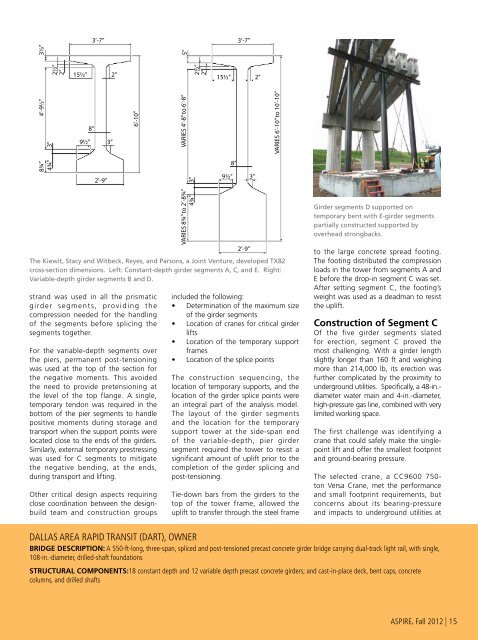
Girder segments D supported on<br />
temporary bent with E-girder segments<br />
partially constructed supported by<br />
overhead strongbacks.<br />
to the large concrete spread footing.<br />
<strong>The</strong> footing distributed the compression<br />
loads in the tower from segments A and<br />
E before the drop-in segment C was set.<br />
After setting segment C, the footing’s<br />
weight was used as a deadman to resist<br />
the uplift.<br />
Construction of Segment C<br />
Of the five girder segments slated<br />
for erection, segment C proved the<br />
most challenging. With a girder length<br />
slightly longer than 160 ft and weighing<br />
more than 214,000 lb, its erection was<br />
further complicated by the proximity to<br />
underground utilities. Specifically, a 48-in.-<br />
diameter water main and 4-in.-diameter,<br />
high-pressure gas line, combined with very<br />
limited working space.<br />
<strong>The</strong> first challenge was identifying a<br />
crane that could safely make the singlepoint<br />
lift and offer the smallest footprint<br />
and ground-bearing pressure.<br />
<strong>The</strong> selected crane, a CC9600 750-<br />
ton Versa Crane, met the performance<br />
and small footprint requirements, but<br />
concerns about its bearing-pressure<br />
and impacts to underground utilities at<br />
Dallas Area Rapid Transit (DART), OWNER<br />
BRIDGE DESCRIPTION: A 550-ft-long, three-span, spliced and post-tensioned precast concrete girder bridge carrying dual-track light rail, with single,<br />
108-in.-diameter, drilled-shaft foundations<br />
STRUCTURAL COMPONENTS:18 constant depth and 12 variable depth precast concrete girders; and cast-in-place deck, bent caps, concrete<br />
columns, and drilled shafts<br />
<strong>ASPIRE</strong>, <strong>Fall</strong> <strong>2012</strong> | 15


