Mlll Pro - Digital readouts, DRO, Magnum Measuring Systems, sargon
Mlll Pro - Digital readouts, DRO, Magnum Measuring Systems, sargon
Mlll Pro - Digital readouts, DRO, Magnum Measuring Systems, sargon

Create successful ePaper yourself
Turn your PDF publications into a flip-book with our unique Google optimized e-Paper software.
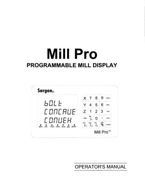
<strong>Mlll</strong> <strong>Pro</strong><br />
PROGRAMMABLE MILL DISPLAY<br />
Sorgoro<br />
'-<br />
I<br />
,_ l-l t ,_<br />
l=l i-i i- t:<br />
['Jii[-_H!_l E<br />
r_ [-iii!-l E lJ<br />
llaaala<br />
, abs inc inc2 lnqh sngr a1c b_h/1h<br />
V<br />
/\tl<br />
:<br />
t7<br />
\./tA<br />
I i+<br />
Z:1<br />
...................<br />
i<br />
23<br />
.t......................<br />
l+<br />
clear i<br />
| _<br />
"|"<br />
i""f,<br />
l,n ', l-<br />
:<br />
-"---_...-"r"<br />
:;l<br />
- -'-<br />
An<br />
}
i<br />
i<br />
Features and Capabilities<br />
MANIJ contains: ..<br />
NORmal mode,<br />
BOLT hole mode; \.<br />
CONCAVE mode;<br />
CONVEX mode,<br />
LNE hole mode;<br />
REFerence mode,<br />
SENSOR mode (optional).<br />
When power up while<br />
8. 8. 8.8.8. 8. 8.8.is flashing<br />
press any key to start from<br />
the NORmal mode. \<br />
i<br />
Sqrgoflo<br />
MEC switch on the rear panel<br />
is used for setting the Machine<br />
Error Compensation.<br />
Bright, efficient LED display<br />
with wide viewing angle<br />
I<br />
iii<br />
!_.<br />
l-t<br />
l:i l_ l=<br />
Internal NonvolatileMemory<br />
maintains data when Power<br />
is turned OFF<br />
Indicators for display modes:<br />
Absolute;<br />
Incremental,<br />
Incremental2..<br />
Inch lmm;<br />
Sensor,<br />
Arc (concave, convex);<br />
Bolt Hole lLine Hole.<br />
---'t<br />
-'1''<br />
i<br />
l-<br />
l- iJii!: i1 !_l !:<br />
l-<br />
l- lJ[-l !-] l= H<br />
,-8<br />
-1 abs<br />
.s ss@s<br />
inc2 inch snsr arc<br />
s<br />
bh/th<br />
!nc_<br />
Power input module atrear has:<br />
Odoff switch;<br />
Fuse protection;<br />
EMI filter for noise protection.
While MENU is displaying, press X, Y or Z<br />
to select an operating mode.<br />
In NORmal mode, press the menu key<br />
to display MENU.<br />
In a selected operating mode ( BOLT, CONCAVE<br />
CONVEX, LINE, REF or SENSOR,) press the<br />
menu key to return to NOR mode.<br />
,In a selected operating mode, press the start<br />
/ key to run.<br />
,In a selected operating mode press the next<br />
key to move to the next step.<br />
tl ';<br />
if'<br />
-ll<br />
tJl<br />
tt:<br />
l<br />
clear<br />
I<br />
1i<br />
'"7".7<br />
ii<br />
/\<br />
i\<br />
/\<br />
\a<br />
\<br />
\\\\\<br />
,,//<br />
bolute or \ Inch or<br />
incremental<br />
milimeter<br />
display<br />
display.<br />
/t<br />
/l<br />
//<br />
/<br />
,il<br />
/<br />
/ l<br />
-?---""''<br />
I<br />
,/:<br />
-<br />
. While MENU is displaying, press the<br />
/ next key to scroll through MENU.<br />
the optional RS232 interface is installed, press<br />
,,,If<br />
...' and hold the print key at power up while<br />
'/<br />
8.8 8.88 8 8 8 is flashing to set RS232 protocol.<br />
infomation to the connecting COMPUTER<br />
andlor PRINTER<br />
Press the +l- key to toggle between inc and inc2.<br />
\.<br />
'\<br />
Preset a dimension if in an incremental mode,<br />
Set the DATUM of a workpiece if in<br />
\ the absolute mode.<br />
\.<br />
\.<br />
\....<br />
.\ \. Center a dimension-divided by 2.<br />
".. Display Cartesian or polar coordinates.<br />
Press and hold at power up while 8 8 8 8 8 8.8.8. is flashrng<br />
to set Scale Resolution, Scale direction, Diameter Enable and Near Zero Warnins.
Introduction<br />
Scope<br />
This manual covers operation of the Sargon Mill <strong>Pro</strong> <strong>Pro</strong>grammable Mill Display.<br />
The Mill <strong>Pro</strong> can be used for basic <strong>DRO</strong> operations or for more advanced<br />
programmable operations.<br />
Getting started<br />
To rapidly gain familiarity with your system and to get the most out of it, the following<br />
is recommended:<br />
l. Install the system as described in Section 3.<br />
2. Set the Mill <strong>Pro</strong> scale resolutions. scale directions etc. as described in Section 5.<br />
3. Once you have completed the setup and exited, the Mill <strong>Pro</strong> will be automatically<br />
switched to NORmal mode. Move the mill axes and verifr the readout displays<br />
direction as expected. Ifnot correct, repeat step 2.<br />
4. Read the appropriate sections ofthis manual depending on the type of tasks to be<br />
performed and try out the various features.<br />
5. Read this manual from cover to cover to become fully acquainted with all<br />
caoabilities.<br />
3
Preparation For Use<br />
Unpacking<br />
Inspect Shipping Containers. Inspect for obvious damage that would indicate<br />
mishandling during shipment. Make note of any indicators, such as: dented corners or<br />
torn sides.<br />
Save Packing Material.<br />
carefully to permit reuse in case it is necessary to return any portion of the equipment.<br />
Notify Carrier In Case of Damage. If the display or other items show any external<br />
damage, or if parts have vibrated or broken loose, the carrier should be notified within<br />
ten days of receipt of shipment.<br />
Check Packing List. Any discrepancy between the items received and the items listed<br />
on the shipment packing list should be reported immediately to the Sargon distributor.<br />
General<br />
installation<br />
notes<br />
WARNING<br />
HAZARDOUS VOLTAGES.<br />
USE EXTREME CAUTION.<br />
All required electrical work should be performed by a qualified electrician.<br />
Mount the Mill <strong>Pro</strong> a minimum of 6 inches away from any motors. The Mill <strong>Pro</strong> may be<br />
mounted to the arm provided, or to a custom machined arm, mount, or stand.<br />
Refer to the applicable manual for scale installation.<br />
Typical display<br />
installation<br />
l.<br />
2.<br />
3.<br />
Remove the large eye bolt located on top<br />
of the milling machine column (Index<br />
l).<br />
Mount the arm (Index 2) as shown.<br />
Bolt the Mill <strong>Pro</strong> to the mounting arm<br />
with the 5/16-18 bolt (Index 4) provided<br />
in the hardware kit.<br />
4
Grounding<br />
The AC outlet should be a three prong grounded outlet (per article 250 ofthe US<br />
National Electrical Code). If it is not, use a grounded adapter and verifu that the adapter<br />
is grounded.<br />
Veriff that the machine is grounded. If it is not, a ground must be installed.<br />
Install a 14 AWG stranded wire (customer provided) from the ground lug located on the<br />
back ofthe Mill <strong>Pro</strong> to the machine power ground connection. Ifthis is not possible,<br />
drilVtap at an altemate location on the machine. Secure the ground wire using star or<br />
split washers to ensure adequate connection. Use an approved anti-oxidation compound<br />
at the connection where the oaint is scraoed.<br />
AG power<br />
Do not use machine power lines for the Mill <strong>Pro</strong>. Use a separate 120 or 240 VAC outlet.<br />
Ifan outlet is not available, one should be installed near the Mill<strong>Pro</strong> mounting location.<br />
The AC power outlet should be ofthe same voltage as that indicated on the<br />
identification/serial number label on the back ofthe Mill <strong>Pro</strong>.<br />
Use the power cord supplied. Do not modifu the power cord in any way.<br />
Routing scale<br />
cables<br />
Connect and secure the scale connectors<br />
the Mill <strong>Pro</strong>. Using tie-wraps, secure the<br />
scale cables and dress any excesslack. Do not wrap any AC power lines with the scale<br />
cables. Maintain a minimum of 6 inch spacing from AC lines and cross at right angles.<br />
5
Cleari ng Al I Memory<br />
CAUTION<br />
The following will occur when memory is cleared:<br />
. Resolutions will be set to 0.0005 inches or 10 micron.<br />
' Scale directions will be set to negative.<br />
. Diameter will be disabled for all axes.<br />
. Near Zero Warning window will be set to * 0.2000 inch.<br />
. Bolt hole, Concave, Convex and Line hole programs will be replaced by sample<br />
demo programs.<br />
. Position information will be lost.<br />
. MEC factors will be set to 1.0.<br />
. All other stored information will be lost.<br />
Selecting<br />
clear all<br />
I LEHT<br />
frLL<br />
After power up and while the display is still<br />
flashing 8.8.8.8.8.8.8.8., press and hold<br />
the clear key to display the CLEAR<br />
ALL screen. To cancel the CLEAR ALL,<br />
press any key except the Xkey.<br />
Press the X key. The Mill <strong>Pro</strong> will prompt<br />
with CLEAR YES ?<br />
ELEHI<br />
TE5<br />
To CANCEL the CLEAR ALL operation,<br />
press any key except the Z key.<br />
To CONTINUE the CLEAR ALL<br />
operation, press the Z k"y. CLEARED will<br />
be momentarily displayed and all memory<br />
will be cleared. The Mill <strong>Pro</strong> will then<br />
automatically go to the setup screens<br />
(Section 5.)<br />
Exiting without<br />
clearing<br />
memory<br />
To exit the clear all screen without clearing memory, press any key except the X and<br />
the Zkey. The Gold Tracer will switch to the NORMAL mode automatically.<br />
6
Setup Screens: Setting Scale Resolutions,<br />
Scale Directions, Diameter Enable, and<br />
Near Zero Warning Window<br />
Description<br />
Scale resolutions, scale directions, diameter enable, scale factors and near zero warning<br />
window are programmed from the Mill <strong>Pro</strong>'s front panel.<br />
They are stored in the Mill <strong>Pro</strong>'s nonvolatile memory. Once set, the Mill <strong>Pro</strong> may be<br />
powered down. When powered up at alater time the settings will still be intact.<br />
Entering the<br />
setup screens<br />
EEEEEBEE<br />
EEEEEEEE<br />
EEEEEEBg<br />
Set the power switch at the rear of the Mill<br />
<strong>Pro</strong> to OFF (0) then back to ON (1). The<br />
display will flash 8.8,8. 8.8.8.8.8.<br />
Press and hold the abs/inc k.y, one of<br />
the setup screens is displayed.<br />
Selecting the<br />
desired setup<br />
screen<br />
r E5 0005<br />
nEt' ,<br />
dtfl nn<br />
NE HT<br />
]ET D<br />
U,NdEU<br />
Press the fleXt key until the desired setup<br />
screen is displayed.<br />
Scale<br />
resolutions<br />
MICRON, mm INCH<br />
10.0 0.01 0.0005<br />
5.0 0.005 0.0002<br />
2.0 0.002 0.0001<br />
1.0 0.001 0.00005<br />
0.5 0.0005 0.00002<br />
0.2 0.0002 0.0000 1<br />
0.1 0.0001 0.000005<br />
Each axis displayed on the Mill <strong>Pro</strong> must be<br />
set to the resolution that matches the scale<br />
being used for the axis. Resolutions<br />
available on the Mill <strong>Pro</strong> are shown to the<br />
left. The scales must be metric. When inch<br />
mode is selected, the metric scale inputs are<br />
converted by the Mill <strong>Pro</strong> to display in<br />
inches.<br />
7
Scale<br />
resolutions<br />
(countinue)<br />
rE1 0c05<br />
IE5 0U0l<br />
rEs 000 t<br />
r E 00005<br />
r E DNDD}<br />
rE1 DDCS<br />
r E5 n005<br />
Repeatedly press the ll€Xt key until the<br />
resolution setup screen is displayed.<br />
Repeatedly press the X , Y or ZUey for the<br />
desired axis until the correct resolution is<br />
displayed.<br />
Scale directions<br />
r E5 0005<br />
f E5 ln u<br />
f E5 l0 u<br />
f E5 ln u<br />
Press the inch/mffi key to change<br />
between inch and metric displays. ln mm<br />
mode the resolutions are displayed in<br />
microns (0.001 mm).<br />
Exit setup mode by pressing any key except<br />
the X, Y, Z, next and inch/mm.<br />
Thedown,dependingonthedirectionoftab1emovement.<br />
Scale direction can be set, in the Mill <strong>Pro</strong>, for each axis, so that movements are properly<br />
displayed.<br />
nE[' -- ,<br />
,- - P05<br />
nEn ,<br />
Repeatedly press the lleXt key until the<br />
scale direction setup screen is displayed.<br />
Press the X, Y or ZUey for the desired axis<br />
to switch between positive and negative<br />
scale directions.<br />
Exit setup mode by pressing any key except the X, Y, Z, next and inch/mm.<br />
Diameter /<br />
radius<br />
When diameter is enabled (set to YES) for an axis, as described below, the scale input<br />
for that axis is doubled. In other words, the displayed dimension is twice the actual<br />
distance traveled. When diameter is disabled (set to fVO) for an axis the displayed<br />
dimension tracks the actual scale movement.<br />
difr fiB<br />
d IH TEs<br />
d ifr {]fr<br />
Repeatedly press the llGXt key until the<br />
DIA YES/NO screen is displayed.<br />
Press the X or Y or Zkey for the desired<br />
axis to switch between diameter enabled<br />
(YES) and disabled (NO).<br />
Exit setup mode by pressing any key excepthe X, Y, Z, neXt and inCh/mm.<br />
8
Near Zero<br />
Warning<br />
A near zero warning window is set for each axis as described below. The near zero<br />
warning indicator is set from the setup screens. When enabled, one of the following<br />
symbols will be displayed when the position is within the near zero warning window.<br />
E<br />
E<br />
This symbol is displayed when zero is being approached from the<br />
positive direction.<br />
This symbol is displayed when zero is being approached from the<br />
negative direction.<br />
Setting the near<br />
zero warning<br />
window<br />
The window setting indicates the range (plus or minus from zero) for which the near<br />
zero warning indicator will be displayed when enabled.<br />
NE fli<br />
lETD<br />
U INdEU<br />
fr 0]0fr0<br />
D 8}]frfr<br />
fr frlDDn<br />
Press the IIGXI key until the AIEA R ZERO<br />
WlNDOlAlscreen is displayed. The default<br />
value is 0.2 inches.<br />
Press the X, Y or ZUey to change the near<br />
zero window for each axis, as required.<br />
Enabling and<br />
disabling the<br />
near zero<br />
warning<br />
indicator<br />
The next setup screen is the NEAR ZERO ON|OFF screen. Press the lleXt key until<br />
the NEAR ZERO ON4OFF screen is displayed.Press theZkey to toggle between near<br />
zero warning enabled (ON) and disabled (OFF).<br />
Exit setup mode by pressing any key except the X, Y, Z, neXt and inCh/mm.<br />
NE flI<br />
lErn<br />
NE frI<br />
eEt0<br />
Exiting the<br />
setup screens<br />
When scale resolutions, scale directions, dia/rad enable and near zero warning are<br />
inch/mm.<br />
X, Y, Z, next and<br />
I
NOR mode and MENU<br />
NOR mode<br />
Press any key while power on and the 8.8.8.8.8.8.8.8. is flashing, the Mill <strong>Pro</strong> will be<br />
switched to its basic operating mode, the NOR mode.<br />
nnnnn<br />
u.uuuu<br />
nnnnn<br />
u.Ltuuu<br />
nnnnn<br />
u.Ltuuu<br />
In the ruOR mode you can set the datum point,<br />
enter numeric al data, use the dual incremental<br />
registers to machine a pocket ... etc.<br />
Press the ffieIlU key will invoke the MENU,<br />
the entrance to all selectable operating modes.<br />
MENU<br />
nnr<br />
ltut<br />
hNL L<br />
hfrL L<br />
I nn[fruE<br />
i nnifruE<br />
I nnuEH<br />
[ frnuEH<br />
LffiE<br />
L INE<br />
[- EF<br />
,= E [-'lr=n i<br />
Press the hOXt key, the MENU will be scrolled<br />
upward. The selectable operating modes are:<br />
NOR (normal);<br />
BOLT;<br />
CONCAVE;<br />
CONVEX;<br />
LINE;<br />
REF (reference);<br />
sE vsoR*.<br />
* Optional<br />
Selecting<br />
an operating<br />
mode<br />
LINE +<br />
I EF +<br />
5E [-l'=nf +<br />
X<br />
Y<br />
z<br />
Refer to the MENU at left, press the X, the Y or<br />
the Z k.y, the Mill <strong>Pro</strong> will be switched to<br />
LINE, REF or SENSOR* mode respectively.<br />
Return to the<br />
NOR mode<br />
BOLT,<br />
CONCAVE,<br />
CONVEX,<br />
LINE,<br />
REF or<br />
SENSOR mode.<br />
10<br />
In any selected operating mode other than ruOR,<br />
press the lTl€llU key, the Mill<strong>Pro</strong> will be<br />
switched back to the NOR mode.
Numerical Data Entry<br />
Keys and their<br />
functions<br />
..........seIect absolute or incremental mode:<br />
.........select inc or inc2 while in the incremental mode;<br />
ElMail 1<br />
.....select axls:<br />
datum<br />
ililT" llo'o"u'"<br />
.cancel;<br />
change the sign of the input;<br />
..preset;<br />
..center line;<br />
trEE,di:ffir ztr<br />
cancer Input Armodes<br />
trtrAdi:ffnEtr<br />
i"Hi,l"nta, lffJ<br />
'c2trtrAdi:ff n ztr<br />
fi::*:;::i' H:trinc'trtratr<br />
'",',ifi:"J,ii"'<br />
ilffJ inc2<br />
tr tr Edi:ffTr z tr tr e<br />
inc orinc2<br />
lncrement mode trtr{tr<br />
Glear current<br />
Divid the<br />
I:1"'entar by ;[r"Jinc2 trtrAtr<br />
two<br />
H?:l-ff", H:r"Jinc2 trtrAA<br />
11
Absolute and<br />
Dual Incremental Modes<br />
The difference<br />
between<br />
absolute and<br />
incremental<br />
modes<br />
For each axis, the Mill <strong>Pro</strong> has one absolute position register and two incremental<br />
position registerso inc and inc2.<br />
The absolute position is the distance between the datum point on the work piece and<br />
another point to which the machine has been moved. The incremental position refers to<br />
distances that are not measured with reference to the datum point, but instead, the<br />
distance is measured between the previous point and some new point.<br />
Absolute and dual incremental registers are both updated during table movement<br />
regardless of which is currently displayed.<br />
Absolute and dual incremental registers are otherwise independent; that is, updating one<br />
will not affect the other.<br />
Absolute and<br />
incremental on<br />
a sample work<br />
piece<br />
Datum (0,0)<br />
\t \l<br />
--f- -r<br />
2.9inches+<br />
1.e inches---l<br />
F-<br />
I<br />
l+Oeinchl | |<br />
/r ,<br />
-/ [- r.o inch -rt- 1.0 inch<br />
-@@<br />
Absolute position<br />
(0.9000, -0.7000)<br />
Incremental position<br />
(1.0000, 0.0000)<br />
Incremental position<br />
(1.0000, 0.0000)<br />
Switching<br />
between<br />
absolute and<br />
incremental<br />
display modes<br />
Press the abS/inC key to switch between absolute and incremental position displays.<br />
LEDs behind the ObS or inC or inC2 indicate which mode is active.<br />
Press the */- key to switch between the two incremental position displays. LEDs<br />
behind the illG or inc2 indicate which mode is active.<br />
12
Double<br />
incremental<br />
registers<br />
The dual incremental registers feature is speciallyimplemented for machining<br />
rectangular shape pocket. In t t9 sE50p{"050 represents the X and Y<br />
displays 1.750. -1.050 represents inc2 registers. Press the */- key<br />
to toggle between em.<br />
Y (0,0) DATUM<br />
r1.0"<br />
I<br />
X<br />
Machine a<br />
pocket using<br />
double<br />
incremental<br />
registers<br />
Above is a sample workpiece with a pocket. The tool is a 0.25 inches end mill.<br />
1. Position the end mill to the datum point(O, 0), preset the absolute X, Y displays to<br />
zero. Move the end mill to position (1.125,-1.125).<br />
O<br />
2. Press abs/inc key to switch to inc mode, preset the X and Y to -1.750,<br />
1 .050<br />
With this setting, the inc<br />
both inc X and inc Y will be zero while reaching position @1 ;<br />
Press +/- key to switch to inc2 mode, preset the X and Y bdtfi to zero.With this<br />
setting, the inc2 X will be zero when the end mill reaches positior@ and both inc2<br />
X and inc2 Y will be zero when position i. reached;<br />
O<br />
3. Press the */- kev to switch to inc<br />
o@@<br />
path; patn; Press rress the tne f/- rF key Key to Io switch Swrlcn to Io inc2 lncz mode mooe and ano machining macnlnlng along the tne 16\1At<br />
path. All destination dimensions of the moving axis are zero as shown on YT4Wa<br />
the box.<br />
-1.750,<br />
1 .050 0.000, 1 .050<br />
0.000, 0.000 1.750,0.000<br />
0.000, 0.000<br />
-1.750,1.050<br />
0.000,0.000<br />
1.750, -1.050<br />
0.000. -1.050 1.750, -1.050<br />
-1.750.0.000 0.000, 0.000<br />
+/-<br />
+/-<br />
13
Cartesian and Polar Goordinates<br />
Description<br />
Dimensions can be displayed as either Cartesian or polar coordinates.<br />
These are best described bv the fieures shown below.<br />
Cartesian<br />
coordinates<br />
t8frfrfrfr<br />
I ? DODE<br />
nnnnn<br />
U.UUUU<br />
Press to switch from polar to Cartesian<br />
coordinates.<br />
X=16.0000<br />
Polar<br />
coordinates<br />
{. ]DDfrDfr<br />
H<br />
lEE1<br />
nnnnn<br />
U.UUUU<br />
Press to switch from Cartesian to polar<br />
coordinates. Numbers cannot be entered<br />
while the Mill <strong>Pro</strong> is in polar mode.<br />
90 deg<br />
1 80 deg<br />
A=36.87<br />
270 deg<br />
14
10<br />
Bolt Hole <strong>Pro</strong>grams<br />
Description<br />
A bolt hole pattern is a series of holes evenly spaced around the circumference of a<br />
circle. There is a sample demo bolt hole pattern in the Mill <strong>Pro</strong>'s memory, you can<br />
change it to create a new pattern, it may then be used as many times as required by<br />
running the program. It will stay intact even when the Mill <strong>Pro</strong> is off.<br />
The Mill <strong>Pro</strong>'s memory hold one bolt hole program with up to 9999 holes.<br />
Bolt hole<br />
pattern around<br />
the entire<br />
circumference<br />
of a circle<br />
The following is the sample demo pattern, its start angle and end angle are the same, the<br />
Mill <strong>Pro</strong> will evenly space the holes around the circumference of the bolt hole pattern.<br />
90 degrees<br />
+Y<br />
4 Holes, evenly spaced<br />
Radius = 0.5000 inches<br />
Hole 2<br />
START ANGLE<br />
/<br />
I END ANGLE<br />
,,<br />
180 degrees -X +X 0 degrees, 360 degrees<br />
.Y<br />
270 degrees<br />
The following information have already been saved into the Mill <strong>Pro</strong>'s memory:<br />
RADIUS 0.5000 inches<br />
START ANGLE<br />
90 degrees<br />
END ANGLE<br />
90 degrees<br />
NUMBER OF HOLES 4<br />
15
Bolt hole<br />
pattern<br />
around a<br />
portion of the<br />
circumference<br />
of a circle<br />
When the start angle and the end angle are not the same, the Mill <strong>Pro</strong> will place the first<br />
hole at the start arigle position and the last hole at the end angle position. The remaining<br />
START ANGLE 1 90 dEgTCES<br />
+Y<br />
4 Holes, evenlY sPaced<br />
Radius = 0.5000 inches<br />
Hole 1<br />
180 degrees -X +X 0 degrees, 360 degrees<br />
-Y<br />
END ANGLE 4 270 degrees<br />
In order to create the bolt hole pattern shown above, the following information must be<br />
programmed into the Mill <strong>Pro</strong>:<br />
RADIUS 0.5000 inches<br />
START ANGLE<br />
90 degrees<br />
END ANGLE<br />
270 degrees<br />
NUMBER OF HOLES 4<br />
Enter the<br />
BOLT mode<br />
Exit the BOLT<br />
mode<br />
press the heXt key to scroll the MENU (section6,page l0) , until the Bo[ris<br />
displayed on the screen. press the X, the Y orthe z key whicheverhappen to coincide<br />
BoLrhole<br />
with the BOLT<br />
mode as below.<br />
05frcn<br />
| frd tus<br />
Press the ffiehU or the Cleal key to exit bolt hole mode'<br />
Once in BOLT mode, press the lleXt key to<br />
view or edit the BOLf hole program or<br />
press the Stdlt key to run the current BOLT<br />
hole program.<br />
16
Creating a bolt<br />
hole program<br />
You can change the parameters (radius, start angle, end angle and holes) on each screen<br />
to create a BOLT hole program, press the h€Xt key to get to the next screen.<br />
If you like to run the program in the Mill <strong>Pro</strong>'s memory, press the St?ft k.y.<br />
fr5frfrfr<br />
i frd tu5<br />
fr frfrfr<br />
5Efr-E fr<br />
Enter the desired RADTUS if different from the<br />
displayed value.<br />
To view or change the next parameter press the<br />
next key.<br />
Enter the desired SIART ANGLE if different<br />
from the displayed value. The first hole will be<br />
determined by the start angle.<br />
To view or change the next parameter press<br />
h€xt key<br />
fr<br />
DDfr<br />
Enter the desired END ANGLE if different<br />
from the displayed value.<br />
E nd fr{-tE<br />
HfrLE5<br />
{ EI 1flUE<br />
E['I d PiDE<br />
If the end angle is the same as the start angle,<br />
the holes will be equally spaced around the<br />
entire circumference of the bolt hole pattern.<br />
If the end angle is not the same as the start<br />
angle, the holes will be equally spaced along a<br />
segment of the circumference of the bolt hole<br />
paffern. The final hole will be determined by the<br />
end angle.<br />
Enter the desired number of HOLES if different<br />
from the displayed value.<br />
When the REC SAVE screen is displayed, the<br />
newly changed parameters will be stored in the<br />
Mill <strong>Pro</strong>'s memory. Press ngxt key to run the<br />
program (continued on next page.)<br />
17
Running a bolt<br />
hole pattern<br />
frN Efr<br />
iENLEi<br />
HNL E<br />
I<br />
nnnnn<br />
U.UUUU<br />
0n000<br />
nnnnn<br />
U.UUULJ<br />
I l{-<br />
"LE - fr500n<br />
ODDON<br />
DDDDfr<br />
E {-td frF<br />
I t{-[LE<br />
The GO TO CENTER screen is momentarily<br />
displayed.<br />
Move the table to position the cutting tool at the<br />
center of the desired bolt hole pattern on the<br />
workpiece, then set both X and Y axes to 0.<br />
OR<br />
If this is the second time through the same bolt<br />
hole pattern around the same center, do not set<br />
X and Y axes to 0.<br />
Press next key.<br />
The HOLE number screen is momentarily<br />
displayed followed by the X and Y coordinates<br />
required for the next hole.<br />
Move the table until the Mill <strong>Pro</strong> displays 0 on<br />
both X and Y axes, then perform the cutting<br />
operation.<br />
Repeat the sequence of:<br />
1. Press the fleXt key.<br />
2. Move the table, until X and Y both are zero.<br />
3. Perform the cutting operation.<br />
until the bolt hole pattern is complete.<br />
The same bolt hole pattern may be run through<br />
as many times as required. For example:<br />
tapping, counter boring, etc.<br />
Press the ffieIlU or the Cleal key to exit bolt hole mode.<br />
18
11<br />
Line Hole <strong>Pro</strong>grams<br />
Description<br />
A line hole pattern is a series of holes evenly spaced along a line segment. There is a<br />
sample demo line hole pattern in the Mill <strong>Pro</strong>'s memory, you can change it to create a<br />
new pattern, it may then be used as many times as required by running the program. It<br />
The Mill <strong>Pro</strong> memory hold one hole program with up to 9999 holes.<br />
Sample line<br />
hole pattern<br />
90 degrees<br />
*Y 4 Holes, evenly spaced<br />
Length = 1.5000 inches<br />
Hole 4<br />
ANGLE<br />
.=-<br />
45 degrees<br />
180 degrees -X +X 0 degrees, 360 degrees<br />
.Y<br />
270 degrees<br />
Above is the sample demo line hole pattern, the fbllowing infbrmation have already<br />
been saved into the Mill <strong>Pro</strong>'s memory.<br />
LENGTH 1 .5000 inches<br />
ANGLE<br />
45 degrees<br />
NUMBER OF HOLES 4<br />
Enter the line<br />
hole mode<br />
Press the ll€Xt keyto scroll the MENU(section6,page 10), until the LllVEis<br />
displayed on the screen. Press the X, the Y or the Z key whichever happen to coincide<br />
with the LINE<br />
LINE hole mode.<br />
Once in the LINE mode, press the ll€Xt key to view or edit the line hole program or<br />
press the St0ft key to run the current LINE hole program.<br />
Exit the line<br />
hole mode<br />
Press the ffiefiU or the Cleal kev to exit LINE hole mode.<br />
19
Creating a line<br />
hole program<br />
You can change the parameters (length, angle and holes) on each screen to create a<br />
LINE hole program, press the fleXt key to get to the next screen.<br />
If you like to run the program in the Mill <strong>Pro</strong>'s memory, press the St?ft key.<br />
i5000<br />
L E NDLH<br />
fr Ll1nfr<br />
frn"L E<br />
Pressing the X to enter the desired LINE<br />
segment length from first hole to final hole if<br />
different from the displayed value.<br />
To view or change the next parameter press the<br />
next key.<br />
Pressing the X to enter the desired ANG LE of<br />
the line segment if different than the displayed<br />
value.<br />
To view or change the next parameter press the<br />
ll€Xt key<br />
HfrLE5<br />
Pressing the X key to enter the desired number<br />
of HOLES if different than the displayed value.<br />
[- E [ 1frUE<br />
E [-t d P{- frL<br />
neit page<br />
Press the heXt key to save the program.<br />
When the REC SAVE screen is displayed, the<br />
program has been stored in the Mill <strong>Pro</strong>'s<br />
memory.<br />
Press the Il€Xt key to run the<br />
program(continued on next page.)<br />
20
Running a line<br />
hole pattern<br />
Lfr Efr<br />
5Lfr t<br />
HfrL E<br />
51fr t<br />
HDLE }<br />
nnnnn<br />
U.|-JULJL'<br />
nn00n<br />
nnnnn<br />
U.|-JUUU<br />
L INE<br />
-?Ll 1 15<br />
-nq1 t5<br />
nnnnn<br />
U.UUUU<br />
ENd frF<br />
L INE<br />
tr<br />
M<br />
The GO TO STARI and HOLE number<br />
screens are momentarily displayed.<br />
Move the table to position the cutting tool at the<br />
first hole of the line hole pattern on the<br />
workpiece, then set both X and Y axes to 0.<br />
Perform cutting operation for first hole.<br />
OR<br />
If this is the second time through the same line<br />
hole pattern with the holes in the same position,<br />
do not set X and Y axes to 0. Move table until<br />
the Mill <strong>Pro</strong> displays 0 on both X and Y axes<br />
then perform the cutting operation.<br />
Press the heXt key.<br />
The HOLE number screen is momentarily<br />
displayed followed by the X and the Y<br />
coordinates required for the next hole.<br />
Move the table until the Mill <strong>Pro</strong> displays 0 on<br />
both X and Y axes, then perform the cutting<br />
operation.<br />
Repeat the sequence of:<br />
l. Press the ll€Xt key.<br />
2. Move the table, until X and Y both are zero.<br />
3. Perform the cutting operation.<br />
until the line hole pattern is complete.<br />
The same line hole pattern may be run through<br />
as many times as required. For example:<br />
tapping, counter boring, etc.<br />
Press the lTl€hU or the Cleaf key to exit line<br />
hole mode.<br />
21
12 CONVEX<br />
Description<br />
A convex surface is shown in the following drawing.The curve is in theXZ plane (it<br />
can also beYZ plane.) We can caculate theZ coordinate with respecto X, then by<br />
using an appropreate ball mill machine the surface along the X axis. But the point by<br />
point calculation is very tedious and error proned.<br />
This CONVEX feature can automatically preset the Z coodinate with respect to X, if the<br />
convex radius and the ball radius is known.<br />
Enter the<br />
CONVEX mode<br />
Select one of<br />
the CONVEX<br />
plane<br />
Press the ll€Xt key to scroll the MENU (section 6, page 10) , until the COIVVEX is<br />
displayed on the screen. Press the X, the Y or the Z key whichever happen to coincide<br />
with the COIVVEX<br />
CONVEX<br />
mode.<br />
R<br />
R<br />
n. lfr -lr=<br />
'=E i- E [-!=<br />
tnnnnn<br />
I Lt.t-t Lt Lt t_t<br />
SELEI E<br />
[]. lE 1E<br />
tnnnnn<br />
tu.LtuL, l_,<br />
THE COVEX IS IN THE XZ PLANE<br />
THIS DRAWING IS NOT ON SCALE<br />
The first screen selects the GONVEX in the XZ<br />
plane; the second screen selects the CONVEX<br />
in the YZ plane.<br />
Press the */- key to change the selection.<br />
The small number is the ball radius Rb;<br />
The big number is the convex radius RC.<br />
Press the heXt kev to continue.<br />
next page<br />
22
Greating a<br />
CONVEX<br />
program<br />
There is a sample demo CONVEX program in the Mill <strong>Pro</strong>'s memory, you can change it<br />
to create a new one, it may then be used as many times as required by running the<br />
[: frNLIEH<br />
{-frd tu1<br />
tnnnnn<br />
IIJ.TJUUU<br />
Pressing the Z key to enter the desired<br />
CONVEX RADIUS if different from the<br />
displayed value.<br />
Press the hOXt key to move to the next step.<br />
SET XY Z<br />
!=fr1L<br />
{- frd lLl ,=<br />
n. lE -l tr_,<br />
Pressing the Z key to enter the desir ed BALL<br />
RADIUS if different from the displayed value.<br />
Press the fleXt key, the Mill <strong>Pro</strong> will display<br />
SEI X Y Z momentarily, then it will display<br />
the X, Y and Z dimension which is the starting<br />
position of the ball mill that shoud be set before<br />
machining.<br />
START<br />
machining<br />
trrEL Ha<br />
L-f<br />
J.nnnn<br />
nnnnn<br />
L'.tJ Lt t_, t_t<br />
nnnnn<br />
U.LI LI TJ L'<br />
J.frnnn<br />
\!= H{- L<br />
nnnnn<br />
u.Lt L, t_t Lt<br />
tfin{ln<br />
nnnnn<br />
LI.IJ 1-' LI L'<br />
fr.\r= l,<br />
23<br />
machining from its left front corner (-3.0000,<br />
0.0000, 0.0000.)<br />
set X dimension equals to -3.0000,<br />
set Y dimension equals to 0.0000 and<br />
setZ dimension equals to 0.0000.<br />
Press the llOXt key, the Mill <strong>Pro</strong> will display<br />
SfARf<br />
momentarily then will display the<br />
calculated Zdimension (0.4515.) This shows<br />
that the CONVEX edge is lower than its center,<br />
and 0.4515 inch of material should be cut alonq<br />
this edge.<br />
Pressing the Stdft key will make the Mill <strong>Pro</strong><br />
to return to SEf X Y Z screen where you can<br />
set the starting coordinates.<br />
Once SIARIed,<br />
the two axes of the<br />
CONVEXplane, X and Z, are linked together<br />
and no longer are changeable by pressing the<br />
keypad, the Z value will be changed with the X<br />
movement accordingly.
START<br />
machining<br />
(continue)<br />
THE COVEX IS IN THE XZ PLANE<br />
THIS DRAWING IS NOT ON SCALE<br />
Cut the surface<br />
by slice<br />
Let us start machining the CONVEX surface.<br />
1. Press the start key to return to the SEf X Y Z screen Move the table so that the<br />
spindle will be pointed to (X:0.0000, Y:0.0000), lower the spindle to just touch the<br />
work piece. Then, set the coordinates equals to (0.0000, 0.0000, 0.0000) on the SEf<br />
X Y Z sqeen.<br />
2. To start from the left edge of the work piece, move the table to (-3.0000, 0.0000,<br />
0.0000), then press the h€Xt key, theZdisplay changed to 0.4515, this is the<br />
amount inZneed to be cut at X: -3.0000.<br />
3. Machine the GOIVVEX surface along the Y axis till the end of the workpiece to cut<br />
a slice, then back.<br />
4. Depending upon the finishing requirement, move the table in small increments along<br />
the X axis. The Mill <strong>Pro</strong> will calculate the Z coordinate, once the Z dimension<br />
become positive, lower the spindle, repeat step 3.<br />
5. As a sequence of X increment (step 4),Y movement and cutting (step 3)theZ<br />
dimension will be chansed and the CONVEX surface will be done.<br />
Exit CONVEX<br />
mode<br />
Press the tTleDU key to exit CONVEX mode.<br />
24
13 CONCAVE<br />
Description<br />
A concave surface is shown in the following drawing.The curve is in theXZ plane (it<br />
can also beYZ plane.) We can caculate theZ coordinate with respecto X, then by<br />
using an appropreate ball mill machine the surface along the X axis. But the point by<br />
point calculation is very tedious and error proned.<br />
This CONCAVE feature can automatically preset the Z coodinate with respect to X, if<br />
the concave radius and the ball radius is known.<br />
CONCAVE RADIUS Rc<br />
Enter the<br />
CONCAVE<br />
mode<br />
THIS DRAWING IS NOT ON SCALE<br />
Press the fleXt key to scroll the MENU(section 6, page l0), until the COIVCAVE is<br />
displayed on the screen. Press the X, the Y or the Z Uey whichever happen to coincide<br />
with the CONCAVE<br />
CONCAVE mode.<br />
fr. iE 1'=<br />
\ELE{:E<br />
lnnnnn<br />
I tJ.U Lt t_t Lt<br />
The first screen selects the COIVCAVE in the<br />
XZ plane; the second screen selects the<br />
CONCAVE intheYZplane.<br />
Press the */- key to change the selection.<br />
Select one of<br />
the CONCAVE<br />
plane<br />
R<br />
Rc<br />
trrELE[:E<br />
[]. lE -1,=<br />
tnnnnn<br />
I Lt.Lt t_t Lt l_t<br />
The small number is the ball radius Rb;<br />
The big number is the concave radius RC.<br />
Press the ll9Xt kev to continue.<br />
25
Creating a<br />
CONCAVE<br />
program<br />
There is a sample demo CONVEX program in the Mill <strong>Pro</strong>'s memory, you can change it<br />
to create a new one, it may then be used as many times as required by running the<br />
I nn[ HuE<br />
[- frd l!_i ,=<br />
tnnnnn<br />
I L'.LI L' I-' L'<br />
Pressing the Z key to enter the desired<br />
CONCAVE RADTUS if different from the<br />
displayed value.<br />
Press the fleXt key to move to the next step.<br />
SET XY Z<br />
hfrL L<br />
[- frrJ lLl tr'<br />
fr. lPt l'=<br />
'=E l= H ,J<br />
Pressing the Z key to enter the desir ed BALL<br />
RADIUS if different from the displayed value.<br />
Press the ll€Xt key, the Mill <strong>Pro</strong> will display<br />
SEf X Y Z momentarily, then it will display<br />
the X, Y and Z dimension which is the starting<br />
position of the ball mill that shoud be set before<br />
machining.<br />
Caculate the<br />
concave depth<br />
Ef<br />
J.nn{ln<br />
nnnnn<br />
t-t.lJ I-, 1_, Lt<br />
nnnnn<br />
U.U L' LI L'<br />
If the width of the work piece is 6 inches, we<br />
set X dimension equals to -3.0000,<br />
set Y dimension equals to 0.0000 and<br />
setZ dimension equals to 0.0000,<br />
to calculate the depth of the CONCAVE.<br />
Press the Il@Xt key, the Mill <strong>Pro</strong> will display<br />
SfARf<br />
J.nnilfr<br />
'=E<br />
onthe<br />
fri L<br />
nnnnn<br />
u.Lt Ll Lt,-l<br />
tnnnn<br />
nnnnn<br />
u.uulJL,<br />
-[].1 F-,gE<br />
26<br />
momentarily then will display the<br />
calculate d Z dimension (-0.4695.) This shows<br />
that the edge of the CONCAVE is higher than<br />
its ceter and if we start machining from<br />
(-3.0000, 0.0000, 0.0000,) we need set the<br />
coordinat equals to (-3.0000, 0.0000, 0.4695)<br />
SEfXYZscreen.<br />
Pressing the Staft key will make the Mill <strong>Pro</strong><br />
to return to SEf X Y Z screen.
START<br />
machining<br />
Cut the surface<br />
by slice<br />
trtEE 'rl<br />
a<br />
rf<br />
tr<br />
f.[]nnfi<br />
nnnnn<br />
u.uLtuLl<br />
fi.\81',=<br />
J.nnnn<br />
'=L F,[-<br />
'tr<br />
fr.4 83tr_,<br />
J.nnfifr<br />
nnnnn<br />
l-t.Lt L, Ll t-,<br />
nnnnn<br />
lJ.Lt L' t_l Lt<br />
CONCAVE RADIUS Rc<br />
Let us start machining the CONCAVE surface.<br />
I . To start from the left edge of the work piece,<br />
move the table to (X:-3.0000, Y:0.0000),<br />
2. Press the start key to return to the<br />
SEI X Y Z screen Move the table so that<br />
the spindle will be pointed to (X:-3.0000,<br />
Y:0.0000), lower the spindle to just touch the<br />
left front corner of the work piece. Because<br />
the edge of the CONCAVE should be 0.4695<br />
inch higher than CONCAVE center, set the<br />
coordinates equals to (-3.0000, 0.0000,<br />
0.46es .).<br />
3.<br />
4.<br />
Press the hBXt key, the Mill <strong>Pro</strong> will display<br />
SfARf momentarily and the Z display<br />
will be changed to 0.0000.<br />
The two axes of the CONCAVE plane, X<br />
and Z, are linked together and no longer are<br />
changeable by pressing the keyp ad, the Z<br />
value will be changed with the X movement<br />
accordingly.<br />
Machine the CONCAVE surface along the<br />
Y axis till the end of the work piece to cut a<br />
slice, then back.<br />
5. Depending upon the finishing requirement,<br />
move the table in small increments along the<br />
X axis. The Mill <strong>Pro</strong> will calculate the Z<br />
coordinate, once the Z dimension become<br />
positive, lower the spindle, repeat step 4.<br />
6. As a sequence of X increment (step 5),<br />
Y movement and cutting (step 4) the Z<br />
dimension will be changed and the<br />
CONCAVE surface will be done.<br />
Exit CONCAVE<br />
mode<br />
THIS DRAWING IS NOT ON SCALE<br />
Press the ffieflU key to exit CONCAVE mode.<br />
27
14 REFERENCE MARKER<br />
Description<br />
Enter the<br />
SEf REF mode<br />
Clear the<br />
existing<br />
REF SET Marker<br />
Searching the<br />
Reference<br />
Marker from a<br />
starting point<br />
The Mill <strong>Pro</strong> can rememberthe position of the REFERENCE Marker for each axis. In<br />
case the machine table has been moved when the power was down, this feature can<br />
relocate the correct position.<br />
Set the power switch at the rear of the Mill <strong>Pro</strong> to OFF (0) then back to ON (1). While<br />
the display is flashing with 8.8.8.8.8.8.8.8., press and hold the St?ft k.y, the Mill <strong>Pro</strong><br />
will enter the SEf REF mode.<br />
EEE [-EF<br />
nn [-EF<br />
rn [-EF<br />
I l= l- '=E !=<br />
Nfr iEF<br />
nn [-EF<br />
[ !_r [- EF<br />
[-EF IL[-d<br />
nn [-EF<br />
Nfr TEF<br />
nn [-EF<br />
'=l= F,{- L l-l<br />
n.J'=[]fi<br />
Nfi iEF<br />
nn {-EF<br />
nnnnn<br />
tJ.tJ Lt t_t tJ<br />
nfr {-EF<br />
The screen display with NO REF, REF SEI, the<br />
NO REF denotes that the REFERENCE Marker<br />
has not been set .<br />
The REF SEf denotes that the REFERENCE<br />
Marker has been set for the axis. If you need to<br />
reset the REF SEf Marker. it is necessary to clear<br />
it first.<br />
To clear the existing REF SEf Marker:<br />
l. Press the clear key, the REF SEf will be<br />
change to CIR REF.<br />
Press the axis' key (in this case, it is Z,) the<br />
display will flash with REF CLRD, then<br />
change to IVO REF.<br />
,El To search for a REFERENCE Marker:<br />
3-l 1. Select an axis by pressing the X, Y or Zkey. If<br />
the X axis is selected, it will flash with<br />
SEARCH, then display the absolute<br />
dimension of this starting point.<br />
28<br />
2. To make the relocation of the starting point<br />
easier, it is better to preset (section 7, page<br />
11) this dimension to zero.<br />
Make sure that the table movement for the<br />
selected axis is in the positive direction Move<br />
the table slowly. When the Marker is detected,<br />
the Mill <strong>Pro</strong> will save the detected position<br />
immediately and flash the display with<br />
FOUND, then display the current position.
To view the<br />
SAVEd REF SET<br />
Marker's<br />
Position Data<br />
Work<br />
Piece<br />
distance to<br />
the Marker<br />
Marker<br />
While in the SEf REF mode,<br />
press the print key, the Mill <strong>Pro</strong><br />
will display NO DATA if there is<br />
no data; otherwise it will display<br />
REF DATA follow by the saved<br />
data.Then display current position.<br />
Note: If the starting point's<br />
coordinate did not reset to zero<br />
before searching, the distance to<br />
the Marker is the reminder of the<br />
saved data minus the starting<br />
point's coordinate.<br />
Exit the<br />
SEf REF mode<br />
To exit from the SEf REF mode, press menU or any number key.<br />
Enter the<br />
REF mode<br />
The function of REF<br />
REF SEf Marker.<br />
Press the fleXt key to scroll the MENU (section 6, page l0) , until the REFis<br />
displayed on the screen. Press the X, the Y or the Z key whichever happen to coincide<br />
with the REF<br />
REF mode.<br />
Searching the<br />
REF SET Marker<br />
Relocate the<br />
Starting point<br />
{- EF<br />
'=E!-E[:E<br />
NN iEF<br />
nfi [ EF<br />
'=E<br />
fr{- [ H<br />
fi.]'=[]fi<br />
nn iErnfi<br />
[-EF<br />
F n!_ind<br />
I E]EE []<br />
ENd NF F<br />
The SEI ECT denotes this axis' Marker data has<br />
been saved and the axis can be selected for<br />
searching.<br />
Press the X key to select this axis, the Mill <strong>Pro</strong><br />
flashes with SEARCH then displays its current<br />
position in absolute mode.<br />
You can press the pfint key to view the saved<br />
REF SEf Marker data.<br />
Make sure that the table movement for the selected<br />
axis is in the positive direction Move the table<br />
slowly. When the REF SEf Marker is detected, the<br />
Mill <strong>Pro</strong> will copy the saved data to the absolute<br />
display register immediately, then flash the<br />
display with FOUND, RESEI 0, END OF F,<br />
and return to menu screen (section 6, page 10.)<br />
To relocate the starting point, select wOR mode at<br />
the menu screen and display in absolute mode;<br />
move the table, once the Mill <strong>Pro</strong> reaches the<br />
the original starting point's position.<br />
29
15<br />
Machine Error Gompensation<br />
Description<br />
A standard vertical milling machine would have no enor if its table movements<br />
followed perfectly straight lines. This, however, is not the case. There will always be<br />
some finite transfer error.<br />
Definition: Transfer Error is the difference between displacement at the linear scale<br />
and displacement at the cutting tool.<br />
Machine tool error is the difference between the actualength ofa standard certified<br />
gauge block and the value displayed by a digital readout when the gauge block is<br />
measured using standard machine shop practices. This error will also be present in any<br />
work piece machined in that axis.<br />
Machine Error Compensation (MEC) multiplies incoming scale signals by a factor such<br />
that the displayed value will be correct. This factor is stored in the Mill <strong>Pro</strong>'s<br />
nonvolatile memory and is set at the factory to 1.000000.<br />
Example: A 10.0000 inch standard gauge block is measured on a knee mill with a<br />
result of 9.9950 inches. MEC will re-proportion this dimension so that<br />
the correct value (10.0000 inches) is displayed. The 0.0050 inch error<br />
has been distributed over the 10.0000 inches oftravel. Thus the<br />
"Machine Error" has been "Compensated" for.<br />
MEC Factor - 10.0000 / 9.9950 : 1.000500<br />
MEC should be a one time job. However, an operator may wish to recalibrate for a<br />
particular area on the machine table where work is to be performed.<br />
Although MEC can improve machine table performance, it is not intended as a<br />
substitute for proper machine maintenance.<br />
Viewing MEC<br />
factors<br />
In NOR mode, press and hold the L:-l key to view the MEC scale factors for all<br />
AXES.<br />
MEC : True Value / Measured Value<br />
30
Clearing MEC<br />
factor<br />
l. In NOR mode, press the X or Y or Z key to selecthe appropriate axis. All but the<br />
leading zero will be blanked and the decimal point will flash for the selected axis.<br />
2. Set the MEC switch 1at rear of unit) to GAL. The uncompensated dimension will<br />
be displayed for the cleared axis.<br />
3. Retum the MEG switch to OFF.<br />
General MEC<br />
calibration<br />
notes<br />
. The MEC procedure is performed on one axis at a time.<br />
' For best results the Mill <strong>Pro</strong> should be calibrated in the units (inch or mm) in which<br />
it will be used.<br />
' The Mill <strong>Pro</strong> should be calibrated on the table areathat is most commonly used.<br />
' Absolute and incremental modes have the same calibration factor for a given axis.<br />
Calibrating MEC<br />
1. Switch to NOR mode.<br />
2. Clear the MEC factor as described above.<br />
3. Measure the gauge block (with the Mill pro) using standard machine shop<br />
procedures and practices.<br />
4. X ory orZ key for<br />
that axis. All but the leading zero will be blanked and the decimal point will flash<br />
for the selected axis.<br />
5. Use the numeric keypad to key in the true value (the actual certified gauge block<br />
length).<br />
6. Set the MEG switch (at rear of unit) to CAL, then retum it to OFF, The<br />
compensated dimension will be displayed for this axis.<br />
7. Measure the gauge block again to ensure the Mill <strong>Pro</strong> is now properly calibrated.<br />
8. Repeathe procedure for the remaining axes ifrequired.<br />
31
RS2 32 Fu nctions (Option)<br />
Description<br />
The RS232 option consists of two serial ports designated "COMPUTER" and<br />
"PRINTER" installed on the back panel of the Mill <strong>Pro</strong>.<br />
RS232 is the communication medium between the Mill <strong>Pro</strong> and the computer (and/or<br />
the printer). The communication code is ASCII.<br />
The printer and the computer may be used independent of each other.<br />
Information can be sent from the Mill <strong>Pro</strong> to the printer, using the Mill <strong>Pro</strong> keypad,<br />
whether a computer is connected or not.<br />
If a computer is also connected, information can be sent from the Mill <strong>Pro</strong> to the printer<br />
using the computer keyboard<br />
Information can also be sent from the computer, using the computer keyboard, to the<br />
Mill <strong>Pro</strong>.<br />
Connector pin<br />
assignments<br />
Cable<br />
Both connectors on the <strong>DRO</strong> are female D825, their pin assignments and signals are:<br />
Pin Number<br />
2<br />
3<br />
4<br />
5<br />
7<br />
Function<br />
Tx<br />
Rx<br />
RTS<br />
CTS<br />
Signal Ground<br />
NULL MODEM CABLE with at least one male (for the Mill <strong>Pro</strong>) DB25 connector.<br />
Computer setup<br />
A Terminal or Personal Computer can interface with the Mill <strong>Pro</strong> through the serial<br />
port.<br />
If using Microsoft Windows 3.x, choose <strong>Pro</strong>gram Manager \ Accessories \ Terminal.<br />
If using Microsoft Windows 95/98, choose <strong>Pro</strong>grams \ Accessories \ Hyper Terminal.<br />
Printer setup<br />
A serial printer can interface with the Mill <strong>Pro</strong> provided they have the same protocol<br />
settinss.<br />
A1
Setting RS232<br />
protocol<br />
Set the power switch at the rear of the Mill <strong>Pro</strong> to OFF (0) then back to ON (1). The<br />
display will flash 8.8.8,8.8,8.8.8.<br />
Press and hold the pfint key until one of the setup screens is displayed.<br />
Press the ll€Xt key to move to the next setup screens.<br />
Default protocol<br />
settings<br />
bfru d[- frL E<br />
1Enfi<br />
The Baud Rate options are: 19200,9600,<br />
4800, 2400,1200,600, 300, 150.<br />
Default is 9600.<br />
Fn[ L ta<br />
nnnE<br />
The Parity options are:<br />
None, Odd, Even, Mark.<br />
Default is None.<br />
dfrE frb iL 1<br />
E<br />
'=EfrFb iEE<br />
I<br />
I<br />
The Data Bits options are:<br />
5, 6,7,9.<br />
Default is 8.<br />
The Stop Bits options are:<br />
1,2.<br />
Default is 1.<br />
When Baud Rate, Parity, Data Bits and Stop Bits are correctly set, they are stored in the<br />
Mill <strong>Pro</strong>'s nonvolatile memory. Once set, the Mill <strong>Pro</strong> may be powered down. When<br />
Ghanging<br />
protocol<br />
settings<br />
Keep pressing the llgXt key until the desired setup screen is displayed.<br />
Press the Y key to change a default setting.<br />
Exit setup mode by pressing any key other than the Y key or the h€Xt key.<br />
A2
Keyboard<br />
equivalents<br />
Most of the Mill <strong>Pro</strong>'s functions can be performed through the computer keyboard.<br />
-- ----<br />
l-_-- -_<br />
Ain<br />
L,, i l, .|<br />
(J i rr/<br />
i<br />
@ooo<br />
@<br />
e<br />
@<br />
@<br />
o<br />
. Numberkeys(0-9.+-<br />
. Computer keys correspond to the remainingMill <strong>Pro</strong> keys as shown.<br />
. P : PRINTER oN, Q: PRINTER oFF.<br />
Printing<br />
information<br />
When the printer is on, information is printed as the Mill <strong>Pro</strong> is operated. The top axis<br />
information is displayed first, followed by the middle axis, then the bottom axis. Some<br />
examples are shown below.<br />
ON<br />
TR ON<br />
NOR 2.0000 0.0000 0.0000<br />
(X is entered with 0)<br />
2.0000 0.0000<br />
NOR BOLT CONCAVE<br />
BOLT CONCAVE CONVEX<br />
Dimensions are printed when a value is<br />
entered on any axis, or when the display<br />
mode is changed.<br />
Function modes are printed when the<br />
menU key or the next key is pressed.<br />
BOLT INCREMENT (change drsplay mode)<br />
RADIUS O.5OOO<br />
t]N BOLT GO TO CENTER 1<br />
0.0000 0.0000 0.0000<br />
HOLE 1 -0.5000 0.0000 0.0000<br />
HOLE 2 0.0000 -0.5000 0.0000<br />
HOLE 3 0.5000 0.0000 0.0000<br />
HOLE 4 0.0000 0.5000 0.0000<br />
END OF 0.0000 0.0000 0.0000<br />
GO TO CENTER 2<br />
Press and hold the pfint key to turn the<br />
printer off.<br />
Press the pfint key to turn the printer back<br />
on.<br />
Press the pfint key to print the current<br />
screen.<br />
A3
Sargon Mill <strong>Pro</strong> quick start-up guide<br />
POWER UP: Turn the power switch on the back plan to ON (1),<br />
the <strong>DRO</strong> will flash with 8.8.8.8.8.8.8.8.<br />
Press any button to start NOR ( n o rm a l)mode.<br />
Press CLEAR button to reset all parameters.<br />
Press A/l button to set parameters.<br />
Press PRINT button to set RS232 protocol.<br />
NOR (normal) mode:<br />
IEBBDO<br />
,/.00u0<br />
nnnnn<br />
U.UUUU<br />
MENU:<br />
At any mode press<br />
to invoke the MENU.<br />
Once the MENU is displayed (as shown at right)<br />
press I nextl to rotate the MENU,<br />
press<br />
tr<br />
tr<br />
tr<br />
to select the mode at its left.<br />
u<br />
E DNTHUE<br />
I DNUEH<br />
tra<br />
Numerical data enter sequences:<br />
selqct<br />
axrs<br />
data input<br />
f_ttr trtrtr<br />
ended<br />
with<br />
preset absolute or<br />
preset incremental.<br />
tr<br />
tr<br />
tr<br />
tr<br />
a<br />
cancel input.<br />
set X incremental.<br />
set Y incremental.<br />
set Z incremental.<br />
ended<br />
with<br />
selqct<br />
axrs<br />
f:l<br />
recall incremental preset.<br />
P1<br />
clear current incremental.<br />
E_l<br />
divid incremental by two.<br />
lA<br />
negate incremental.<br />
Absolute refers to the datum(O,0) point.<br />
Incremental refers to the previous point.<br />
Press @<br />
to toggle the inc(incremental)<br />
and the inc2 displays for machine a pocket.<br />
Absolute<br />
t Z.V lnCnes I<br />
I<br />
1----A bs o I u te__________1<br />
| 1.9 inches I<br />
Df,tK lAbsolute i<br />
'"\l*<br />
T'<br />
Absolute<br />
0.7 inch<br />
t<br />
o'9 inch I<br />
ltl<br />
I<br />
I Incremental r Incremental I<br />
b- 10 inch --rk- 1.0 inch -+l<br />
L INE<br />
[-EF<br />
5E i15D[-<br />
-^^,-<br />
+/-<br />
-1.750, 1.050<br />
0.000.0.000<br />
0.000. -1.050<br />
-1.750.0.000<br />
1.750.0.000<br />
0.000, 0.000<br />
1.750. -1.050
BOLT<br />
HOLE<br />
Radius = 2.0000 inches<br />
Startangle=0degree<br />
Endangle = 0degree<br />
Holes - 4<br />
LINE<br />
HOLE<br />
Length = 2.0000 inches<br />
Angle = 45 degrees<br />
Hole 4<br />
+X 0 degrees<br />
5 degrees<br />
Select BOLT on the MENU to enter this mode,<br />
press he:t-l to view or edit the existing<br />
program or press rffim to run the program.<br />
Press @ or @ to exit.(see section 10,<br />
Select LINE on the MENU to enter this mode.<br />
press hej-l to view or edit the existing<br />
program or press @ to run the program.<br />
Press @ or @ to exit.(see section 11)<br />
CONCAVE:<br />
CONVEX:<br />
THE COVEX IS IN<br />
THE YZ PLANE<br />
CONCAVE RADIUS Rc<br />
Select CONVEX on the MENU to enter this<br />
mode, convex can be in the YZ plane (as<br />
shown left) or in the XZ plane.<br />
Press f-+fi to select the plane.<br />
Press @ to view or edit the ball radius<br />
and the convex radius.<br />
After set the X, Y, and Z dimension, press<br />
@ to start, the two axes of the convex pla<br />
(Y, Z as shown left) will be linked together.<br />
Move the table in Y, the Z axis will show the<br />
dimension other than zero, move the table<br />
alone X axis to cut the work piece.<br />
see section 13<br />
Select CONVEX on the MENU to enter this<br />
mode, convex can be in the YZ plane (as<br />
shown left) or in the XZ plane.<br />
Press @ to select the plane.<br />
Press @ to view or edit the ball radius<br />
and the convei radius.<br />
After set the X, Y, and Z dimension, press<br />
@ to start, the two axes of the convex plane<br />
(Y, Z as shown left) will be linked together.<br />
Move the table in Y, the Z axis will show the<br />
dimension other than zero, move the table<br />
alone X axis to cut the work piece.<br />
(see section 12)