Installation and Operation Manual - Neptronic
Installation and Operation Manual - Neptronic
Installation and Operation Manual - Neptronic

You also want an ePaper? Increase the reach of your titles
YUMPU automatically turns print PDFs into web optimized ePapers that Google loves.
air<br />
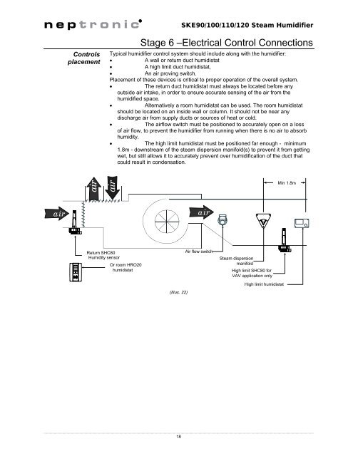
SKE90/100/110/120 Steam Humidifier<br />
Controls<br />
placement<br />
Stage 6 –Electrical Control Connections<br />
Typical humidifier control system should include along with the humidifier:<br />
<br />
A wall or return duct humidistat<br />
<br />
A high limit duct humidistat,<br />
<br />
An air proving switch.<br />
Placement of these devices is critical to proper operation of the overall system.<br />
<br />
The return duct humidistat must always be located before any<br />
outside air intake, in order to ensure accurate sensing of the air from the<br />
humidified space.<br />
<br />
Alternatively a room humidistat can be used. The room humidistat<br />
should be located on an inside wall or column. It should not be near any<br />
discharge air from supply ducts or sources of heat or cold.<br />
<br />
The airflow switch must be positioned to accurately open on a loss<br />
of air flow, to prevent the humidifier from running when there is no air to absorb<br />
humidity.<br />
<br />
The high limit humidistat must be positioned far enough - minimum<br />
1.8m - downstream of the steam dispersion manifold(s) to prevent it from getting<br />
wet, but still allows it to accurately prevent over humidification of the duct that<br />
could result in condensation.<br />
air<br />
Min 1.8m<br />
air air<br />
Return SHC80<br />
Humidity sensor<br />
Or room HRO20<br />
humidistat<br />
(Illus. 22)<br />
Air flow switch<br />
Steam dispersion<br />
manifold<br />
High limit SHC80 for<br />
VAV application only<br />
High limit humidistat<br />
18