MODEL T200-F18 MODEL T125-F18 Finish Nailers ... - Paslode
MODEL T200-F18 MODEL T125-F18 Finish Nailers ... - Paslode
MODEL T200-F18 MODEL T125-F18 Finish Nailers ... - Paslode

Create successful ePaper yourself
Turn your PDF publications into a flip-book with our unique Google optimized e-Paper software.
P<br />
<strong>MODEL</strong> <strong>T200</strong>-<strong>F18</strong><br />
<strong>MODEL</strong> <strong>T125</strong>-<strong>F18</strong><br />
<strong>Finish</strong> <strong>Nailers</strong><br />
IMPORTANT!<br />
DO NOT DESTROY<br />
It is the customerʼs responsibility to have all<br />
operators and service personnel read and<br />
understand this manual.<br />
OPERATING MANUAL AND<br />
SCHEMATIC
INTRODUCTION<br />
The PASLODE ® <strong>T200</strong>-<strong>F18</strong> and <strong>T125</strong>-<strong>F18</strong> finish nailers are quality-built tools designed for use in<br />
residential trim applications. These tools will deliver efficient, dependable performance when used<br />
according to the manufactures guidelines. Please study this manual including the safety<br />
instructions to fully understand the operation of these tools.<br />
TOOL AND FASTENER SPECIFICATIONS ................................................... 3<br />
SAFETY INSTRUCTIONS .............................................................................. 4<br />
INSTRUCTIONS FOR LOADING ................................................................... 5<br />
EXPLODED VIEW AND SPARE PARTS LIST ............................................... 6<br />
ACCESSORIES .............................................................................................. 8<br />
TOOL WARRANTY AND LIMITATIONS<br />
2
TOOL AND FASTENER SPECIFICATIONS<br />
<strong>MODEL</strong> NO. <strong>T200</strong>-<strong>F18</strong> (Part# 500959) <strong>T125</strong>-<strong>F18</strong> (Part#501161)<br />
HEIGHT 9-3/4"<br />
WIDTH 2-3/8"<br />
LENGTH 9-3/4"<br />
7-1/2”<br />
2-3/8”<br />
9-2/3”<br />
WEIGHT<br />
2.1lbs.<br />
1.75 lbs.<br />
NAIL LENGTH 5/8" - 2" 5/8” - 1-1/4”<br />
SHANK DIAMETER 18 gauge<br />
OPERATING PRESSURE 70 to 100 p.s.i.<br />
TOOL AIR FITTINGS:<br />
This tool uses a 1/4” N.P.T. male plug. The inside diameter should be .28” (7mm)<br />
or larger. The fitting must be capable of discharging tool air pressure when<br />
disconnected from the air supply.<br />
OPERATING AIR PRESSURE:<br />
70 to100 p.s.i. Select the operating air pressure within this range for best tool<br />
performance.<br />
DO NOT EXCEED THIS RECOMMENDED OPERATING PRESSURE.<br />
3
SAFETY INSTRUCTIONS<br />
SAFETY FIRST<br />
These safety instructions provide information necessary<br />
for safe operation of <strong>Paslode</strong> ® tools. DO NOT ATTEMPT<br />
TO OPERATE THE TOOL UNTIL YOU READ AND<br />
UNDERSTAND ALL SAFETY PRECAUTIONS AND<br />
MANUAL INSTRUCTIONS.<br />
WEAR EYE AND HEARING PROTECTION<br />
Always wear hearing and eye protection devices, that<br />
conform to ANZI Z87.1 requirements, when operating or<br />
working in the vicinity of a tool. As an employer you are<br />
responsible for enforcing the use of eye protection.<br />
Wear hard hats in environments that require their use.<br />
THE TOOL MUST BE USED ONLY FOR THE PUR-<br />
POSE FOR WHICH IT WAS DESIGNED<br />
Do not throw the tool on the floor, strike the housing in<br />
any way or use the tool as a hammer to knock<br />
material into place.<br />
NEVER ENGAGE IN HORSEPLAY WITH THE TOOL<br />
The tool is not a toy so do not use it like one. Never<br />
engage in horseplay with the tool or point it at yourself<br />
or any other person, even if you think it is not loaded.<br />
NEVER ASSUME THE TOOL IS EMPTY<br />
Check the magazine for fasteners that may be left in the<br />
tool. Even if you think the tool is empty or disconnected,<br />
never point it at anyone or yourself. Unseen fasteners<br />
could fire from the tool.<br />
NEVER CLAMP THE TRIGGER IN A LOCKED OR<br />
OPERATING POSITION<br />
The trigger of the tool must never be tampered with,<br />
disabled or clamped in a locked or operating position<br />
since this will cause the tool to drive a fastener any time<br />
the work contacting element depressed.<br />
DO NOT LOAD FASTENERS WITH THE AIR LINE<br />
CONNECTED, OR WITH THE TOOL TRIGGER OR<br />
WORK CONTACTING ELEMENT DEPRESSED<br />
When loading fasteners into the tool be sure you<br />
disconnect the air line and that you do not depress the<br />
trigger or work contacting element.<br />
OPERATE THE TOOL ONLY ON A WORKPIECE<br />
The tool should be operated only when it is in contact<br />
with the workpiece. Even then you should be careful<br />
when fastening thin material or working near the edges<br />
and corners of the workpiece since the fasteners may<br />
drive through or away from the workpiece.<br />
DISCONNECT THE TOOL WHEN NOT IN USE<br />
Always disconnect the tool from the air line when it is<br />
not in use, when you leave the work area or when<br />
moving the tool to a new location. The tool should<br />
never be left unattended because people who are<br />
not familiar with the tool might handle it and injure<br />
themselves or others.<br />
CARRY THE TOOL ONLY BY THE HANDLE<br />
Always carry the tool by the handle only. Never carry<br />
the tool by the air hose or with the trigger depressed<br />
since you could drive a fastener unintentionally and<br />
injure yourself or someone else.<br />
DO NOT WEAKEN THE TOOL HOUSING<br />
The tool housing is a pressure vessel and should never<br />
be weakened by having your company’s name, area<br />
of work or anything else stamped or engraved into its<br />
surface.<br />
DISCONNECT THE TOOL WHEN PERFORMING<br />
REPAIRS AND CLEARING JAMS<br />
Never attempt to clear a jam or repair a tool unless you<br />
have disconnected the tool from the air line and<br />
removed all remaining fasteners from the tool.<br />
ALWAYS USE THE PROPER FITTING FOR THE<br />
TOOL<br />
Only MALE pneumatic type air connectors should be<br />
fitted to the tool, so that high pressure air in the tool is<br />
vented to atmosphere as soon as the air line is<br />
disconnected.<br />
NEVER install FEMALE quick disconnect couplings on<br />
the tool. Female couplings will trap high pressure air<br />
in the tool when the air line is disconnected, leaving<br />
the tool charged and able to drive at least one fastener.<br />
DO NOT EXCEED THE MAXIMUM RECOMMENDED<br />
AIR PRESSURE<br />
Operate the tool only at the recommended air pressure.<br />
Do not exceed the maximum air pressure marked<br />
on the tool. Be sure the air pressure gauge is<br />
operating properly and check it at least twice a day.<br />
Never use any bottled air or gases such as oxygen to<br />
operate the tool since they could cause the tool to<br />
explode.<br />
INSPECT TOOL FOR PROPER OPERATION<br />
Clean the tool at least daily and lubricate as required.<br />
Never operate a dirty or malfunctioning tool.<br />
DO NOT DISABLE OR REMOVE THE WORK CON-<br />
TACTING ELEMENT<br />
This tool is equipped with a safety mechanism, called a<br />
work contacting element, to help prevent<br />
accidental firing. Never tamper with, disable or remove<br />
the work contacting element. Do not use the tool unless<br />
the work contacting element is working properly. The<br />
tool could fire unexpectedly.<br />
WARNING<br />
Failure to follow any of the above instructions could result in severe personal<br />
injury to tool user and bystanders or cause damage to tool and property.<br />
USE ONLY PASLODE RECOMMENDED PARTS AND<br />
FASTENERS<br />
Use only parts and fasteners specifically designed and<br />
recommended by <strong>Paslode</strong> for use in the tool and for<br />
work to be done. Using unauthorized parts and<br />
fasteners or modifying the tool in any way creates<br />
dangerous situations. Replace all missing warning<br />
labels---refer to tool schematic for correct placement<br />
and part number.<br />
Contact your local <strong>Paslode</strong> Representative for presentation of <strong>Paslode</strong>’s Safety Awareness Program<br />
4
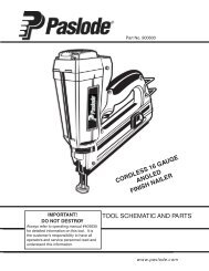
INSTRUCTIONS FOR LOADING<br />
Step No. 1 – Grasp the finish nailer firmly with one hand and press the orange magazine release button at the<br />
rear of the magazine and pull the magazine back towards you.<br />
Step No. 2 – Insert the strip of 18 gauge finish nails with the point of the fastener facing down and place the point<br />
of the fastener into the bottom of the magazine channel. Placing fasteners on the top of the magazine will cause<br />
jamming.<br />
Step No. 3 – Push the magazine firmly towards the front of the tool until it locks in place. The tool is now ready for<br />
use.<br />
5
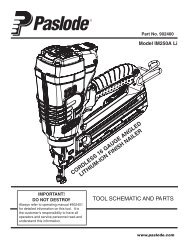
PARTS LEGEND <strong>T200</strong>-<strong>F18</strong>, 500959<br />
<strong>T125</strong>-<strong>F18</strong>, 501161<br />
1 500976 1 Deflector<br />
2 500977 4 Bolt w/ Flat Washer<br />
3 500978 1 Hex Soc. Hd. Screw<br />
4 500979 1 Cap (<strong>T200</strong>)<br />
501170 1 Cap (<strong>T125</strong>)<br />
5 500980 1 Seal<br />
6 500981 1 Compression Spring<br />
7 500982 1 O-Ring<br />
* 8 500983 1 O-Ring<br />
* 9 500984 1 Head Valve Piston<br />
10 500985 1 O-Ring<br />
11 500986 1 Gasket, Cap<br />
12 500987 1 Piston Ring<br />
* 13 500988 1 O-Ring<br />
* 14 500989 1 Piston Assembly (<strong>T200</strong>)<br />
501171 1 Piston Assembly (<strong>T125</strong>)<br />
15 500990 1 Cylinder (<strong>T200</strong>)<br />
501172 1 Cylinder (<strong>T125</strong>)<br />
16 500991 1 O-Ring<br />
* 17 500992 1 Cylinder Ring<br />
18 500993 1 Bumper<br />
19 500994 1 Driver Guide (<strong>T200</strong>)<br />
501173 1 Driver Guide (<strong>T125</strong>)<br />
20 500995 1 O-Ring<br />
21 500996 1 Trigger Valve Head<br />
22 500997 1 Spring<br />
23 500998 1 Plunger<br />
➔ 24 500999 1 O-Ring<br />
25 501082 1 O-Ring<br />
26 501083 1 Plunger Cap<br />
➔<br />
➔<br />
➔<br />
27 501084 2 Roll Pin<br />
28 501085 1 Trigger Lever<br />
29 501086 1 Trigger<br />
30 501087 1 Roll Pin<br />
31 501088 1 Trigger Pivot Pin<br />
32 501089 2 Urethane Retainer<br />
33 501090 1 Housing Assembly<br />
34 501091 1 Air Plug<br />
35 501092 1 Dust Cover<br />
36 501093 2 Bolt Assembly (<strong>T200</strong>)<br />
501176 2 Bolt Assembly (<strong>T125</strong>)<br />
37 501094 1 Front Cover<br />
38 501095 1 Front Guide (<strong>T200</strong>)<br />
501177 1 Front Guide (<strong>T125</strong>)<br />
39 501096 1 Fixed Pin<br />
40 501097 1 Hex Soc Hd Bolt<br />
41 501098 1 Back Plate (<strong>T200</strong>)<br />
501178 1 Back Plate (<strong>T125</strong>)<br />
42 501099 1 Fixed Magazine (<strong>T200</strong>)<br />
501179 1 Fixed Magazine (<strong>T125</strong>)<br />
43 501100 1 Flat Bar (<strong>T200</strong>)<br />
501180 1 Flat Bar (<strong>T125</strong>)<br />
44 501101 2 Bolt Assembly<br />
* Denotes Normal Wear Items.<br />
** Make sure Warning Label (500492 or 501197) is properly affixed.<br />
Replace if necessary.<br />
Label available at no charge through the Service Parts Dept.<br />
▲ Apply Loctite 242 (Blue) Part No. 093500.<br />
➔ Denotes Change<br />
45 501102 1 Stop<br />
46 501103 1 Bracket (<strong>T200</strong>)<br />
501187 1 Bracket (<strong>T125</strong>)<br />
47 501104 1 Follower (<strong>T200</strong>)<br />
501181 1 Follower (<strong>T125</strong>)<br />
48 501105 1 Shaft<br />
49 501106 1 Follower Spring (<strong>T200</strong>)<br />
501183 1 Follower Spring (<strong>T125</strong>)<br />
50 501107 1 Moveable Magazine (<strong>T200</strong>)<br />
501182 1 Moveable Magazine (<strong>T125</strong>)<br />
51 501108 1 Spring Cover<br />
52 501109 1 Latch (<strong>T200</strong>)<br />
501184 1 Latch (<strong>T125</strong>)<br />
53 501110 1 Latch Pin (<strong>T200</strong>)<br />
501185 1 Latch Pin (<strong>T125</strong>)<br />
54 501111 1 Lock Spring<br />
55 501112 1 Latch Cover (<strong>T200</strong>)<br />
501186 1 Latch Cover (<strong>T125</strong>)<br />
56 501113 2 Tap Bolt<br />
57 501191 1 W.C.E. Guide<br />
58 501115 1 Roll Pin<br />
59 501192 1 W.C.E. Spring<br />
60 501193 1 Upper W.C.E.<br />
61 501174 1 E-Ring<br />
62 501175 1 Interm. W.C.E. (<strong>T200</strong>)<br />
501195 1 Interm. W.C.E. (<strong>T125</strong>)<br />
63 501120 1 Lower W.C.E. (<strong>T200</strong>)<br />
501196 1 Lower W.C.E. (<strong>T125</strong>)<br />
64 501121 1 Protective Tip<br />
65 501122 1 Anchor Block<br />
66 501123 1 Magazine Spacer<br />
67 501124 1 Lock Spring<br />
68 501125 1 Latch<br />
69 501126 1 Flat Washer<br />
70 501127 1 Hex Soc Hd Bolt<br />
71 501128 1 Bolt Assembly<br />
72 501188 1 W.C.E. Stop<br />
73 501130 1 Hex Soc Hd Bolt<br />
74 501131 1 Lock Nut<br />
75 500492 1 Warning Label (<strong>T200</strong>)<br />
501197 1 Warning Label (<strong>T125</strong>)<br />
76 501134 1 Magazine Label (<strong>T200</strong>)<br />
501198 1 Magazine Label (<strong>T125</strong>)<br />
77 501135 2 Housing Label<br />
78 501189 1 Hex Socket Button Hd Bolt<br />
79 501190 1 Stop<br />
80 501194 1 Adjuster<br />
81 501271 1 O-Ring<br />
82 501272 1 End Cap<br />
83 501273 1 O-Ring<br />
➔ 84 219260 1 Insert, Long<br />
➔ 85 219261 1 Insert, Short<br />
➔ 86 501387 1 Trigger Spring<br />
6<br />
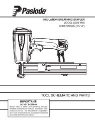
A IR CONSUMPTION - SCFM/F A STEN E R<br />
55<br />
50<br />
45<br />
40<br />
35<br />
30<br />
25<br />
20<br />
0.025<br />
0.032<br />
0.039<br />
0.026<br />
0.046<br />
0.029<br />
0.033<br />
0.022<br />
70 80 90 100<br />
AIR PRESSURE - PSIG<br />
<strong>T200</strong>-<strong>F18</strong><br />
<strong>T125</strong>-<strong>F18</strong>
84<br />
82 83<br />
<strong>T200</strong>-<strong>F18</strong><br />
500959<br />
<strong>T125</strong>-<strong>F18</strong><br />
501161<br />
86<br />
77<br />
81<br />
85<br />
219254<br />
51<br />
75<br />
55<br />
76<br />
WARNING<br />
All parts must be periodically inspected and replaced if<br />
worn or broken. Failure to do this can affect the toolʼs<br />
operation and present a safety hazard.<br />
7
ACCESSORIES<br />
Safety Glasses<br />
Clear<br />
Part No.<br />
402510<br />
Lubricants and Loctite<br />
Loctite 242 (Blue)<br />
Lubricating Oil 16 oz.<br />
Lubricating Oil with Anitfreeze 8 oz.<br />
Chemplex 710 Lubricant 1lb.<br />
Part No.<br />
Part No.<br />
Part No.<br />
Part No.<br />
093500<br />
403720<br />
219090<br />
403734<br />
Degreaser Cleaner<br />
Ideal cleaner for all <strong>Paslode</strong> tools.<br />
Part No.<br />
219086<br />
Sequential Operating Kit<br />
This special attachment is designed for sequential operation<br />
(stops “contact” firing). The operator must depress and hold the<br />
work contacting element against the work surface before pulling<br />
the trigger. This sequence must be repeated each time the tool<br />
drives a fastener.<br />
Contact Trip Trigger<br />
This kit allows for successive or “bounce” firing.<br />
Part No. 219254<br />
Part No. 219265<br />
PRINTED IN U.S.A.<br />
© 2008, Illinois Tool Works, Inc.<br />
PAn<br />
Illinois Tool Works Company<br />
888 Forest Edge Drive<br />
Vernon Hills, Illinois 60061-3105<br />
405645-6<br />
10/08