Quickguide - UNIPRO
Quickguide - UNIPRO
Quickguide - UNIPRO

Create successful ePaper yourself
Turn your PDF publications into a flip-book with our unique Google optimized e-Paper software.
Quick Guide<br />
Unipro Laptimer<br />
6003<br />
Version 1.45<br />
5. September 2009<br />
Go faster faster<br />
<strong>UNIPRO</strong> ApS<br />
VIBORG HOVEDVEJ 24<br />
DK-7100 VEJLE<br />
DENMARK<br />
Tel.: +45 75 85 11 82<br />
Fax: +45 75 85 17 82<br />
www.uniprolaptimer.com<br />
mail@uniprolaptimer.com
Introduction ............................................................................................................................. 3<br />
Get ready to go! ...................................................................................................................... 4<br />
Do you have the necessary accessories? ............................................................................................ 4<br />
Installation .............................................................................................................................................. 5<br />
Display unit ............................................................................................................... 5<br />
Main box ................................................................................................................... 5<br />
RPM sensor ................................................................................................................ 8<br />
Receivers .................................................................................................................. 8<br />
AMB Loop receiver ..................................................................................................................................... 8<br />
Magnet receiver ......................................................................................................................................... 9<br />
Infrared receiver ........................................................................................................................................ 9<br />
Temperature sensors ................................................................................................. 10<br />
Cylinder head sensor ................................................................................................................................. 10<br />
Exhaust sensor ......................................................................................................................................... 10<br />
Water sensor ............................................................................................................................................ 11<br />
Wheel sensor kit ........................................................................................................ 12<br />
The sensor disc ......................................................................................................................................... 12<br />
The wheel sensor ...................................................................................................................................... 13<br />
Basic functions and setup .................................................................................................................... 15<br />
Display buttons ......................................................................................................... 15<br />
Magnet count ............................................................................................................ 16<br />
Magnet delay ............................................................................................................ 17<br />
More settings ............................................................................................................................................ 17<br />
Practice and race using the basic functions ...................................................................... 18<br />
Operating modes ................................................................................................................................. 18<br />
First lap mode ........................................................................................................... 18<br />
Running mode ........................................................................................................... 19<br />
Pit mode .................................................................................................................. 20<br />
Normal data view ...................................................................................................... 20<br />
Graphical data view ................................................................................................... 20<br />
PC mode .................................................................................................................. 21<br />
Split measure mode ................................................................................................... 21<br />
Defining the split points with the use of the wheel sensor ................................................ 21<br />
Time run mode .......................................................................................................... 22<br />
Clear all Laps ............................................................................................................ 22<br />
Take advantage of the advanced features .......................................................................................... 23<br />
Split points ........................................................................................................................................... 23<br />
Splits with magnet stripes ........................................................................................... 23<br />
Splits with wheel sensor ............................................................................................. 23<br />
Viewing the split points .............................................................................................. 24<br />
Editing the split points ................................................................................................ 24<br />
Typical track with 6 split points ................................................................................................................... 25<br />
Temperature sensors .......................................................................................................................... 25<br />
Setup the temperature inputs ...................................................................................... 25<br />
Temperature inputs ................................................................................................... 26<br />
Temperature warning points ........................................................................................ 26<br />
Analyse your data ................................................................................................................................ 26<br />
Data Analyser ........................................................................................................... 26<br />
PC Analyser .............................................................................................................. 26<br />
<strong>UNIPRO</strong> – The original Laptimer 2
Introduction<br />
Thank you for trusting us to deliver the most advanced Laptimer on the market.<br />
This Manual includes detailed information about your Unipro Laptimer. If you need a quick<br />
overview of the functions, and a guide to the daily use, you may want to look at the QuickGuide<br />
first.<br />
The Unipro Laptimer has several unique features and will measure every piece of information with<br />
a speed and accuracy you have only dreamt about! It really enables you to use your Laptimer as a<br />
tool to go faster, faster.<br />
We did all we could to make your investment as future proof as possible and you should be able to<br />
enjoy it in many years to come. Therefore it is possible to expand the Laptimer with new<br />
accessories as they are being developed.<br />
If you have a special request either for new accessories or for a new feature, please let us know.<br />
We constantly try to develop our products with the most useful features so you can use the<br />
Laptimer to go faster, faster but we always appreciate good ideas from the users of our products.<br />
If you have any problems or questions regarding your Unipro Laptimer we will make sure to give<br />
you the necessary support.<br />
Please e-mail your questions to support@uniprolaptimer.com or contact your local dealer.<br />
Good luck on the tracks!<br />
<strong>UNIPRO</strong> ApS<br />
Viborg Hovedvej 24<br />
DK-7100 Vejle<br />
Denmark<br />
Web: www.uniprolaptimer.com<br />
E-mail: mail@uniprolaptimer.com<br />
<strong>UNIPRO</strong> – The original Laptimer 3
Get ready to go!<br />
In this chapter, we will give you the most necessary information about what to do before you can<br />
start using your Laptimer. If you are an experienced user, looking for exact information, you may<br />
want to jump to the reference manual.<br />
Do you have the necessary accessories?<br />
If you have bought the basic package you should have following parts to your Laptimer:<br />
Main Box Display Unit Receiver – Loop, Magnet or IR<br />
RPM Sensor<br />
You may also have bought any of these extra accessories:<br />
Cylinder Head Sensor Water Sensor T-Junction<br />
Exhaust Sensor Kit Speed Kit USB Cable<br />
The Unipro Laptimer can work with three different temperature sensors at the same time.<br />
<strong>UNIPRO</strong> – The original Laptimer 4
Installation<br />
Your Laptimer is a precision instrument and you should take the necessary time to ensure correct<br />
installation. A basic rule is to start from the sensors and go back to the Laptimer, never the other<br />
way. If cables are too long, they should always be looped at the end near the Laptimer. Use<br />
plenty of strips to fix the cables to the frame.<br />
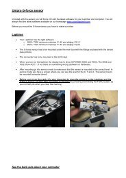
DISPLAY UNIT<br />
The Display Unit is mounted on the steering wheel. Due to the ultra thin Display Unit, you will not<br />
have any problems with regulations.<br />
Nut<br />
Metal washer<br />
Rubber washer<br />
Gray washer<br />
Steering wheel<br />
Rubber washer<br />
Display unit<br />
Figure 1. Display unit mounted on steering wheel<br />
First, the Display Unit is mounted on the steering<br />
wheel. Choose a hole that gives a good placement at the<br />
top of the steering wheel. On some steering wheels, it is<br />
necessary to make the hole a little bigger.<br />
Remove the nut, the gray washer and one of the two<br />
black rubber washers. These parts are mounted on the<br />
back side of the steering wheel, as shown in figure 1.<br />
It is important to keep the right order of the washers.<br />
Please follow this sequence:<br />
Nut – metal washer – gray plastic washer – black rubber<br />
washer – steering wheel – black rubber washer – Display<br />
Unit.<br />
Tighten the nut when the display is strait and centered in the<br />
steering wheel. This picture shows the correct mounted<br />
Display Unit.<br />
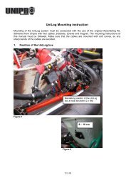
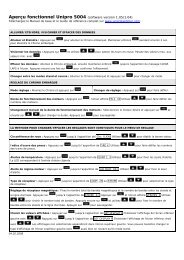
MAIN BOX<br />
The main box is mounted behind the front cover. The following picture is showing the main box<br />
and its components.<br />
<strong>UNIPRO</strong> – The original Laptimer 5
Screw with washer<br />
Front cover<br />
Vibration damper<br />
Main box<br />
Figure 2. Main Box with fittings<br />
The main Box is mounted behind the front cover.<br />
First, a 6.5 mm hole is drilled in the cover. Some karts have a<br />
recess in the coat suitable for drilling the hole in. If you press hard<br />
on the sticker, you can see where to drill the hole. It is a good<br />
idea to look from the back before drilling!<br />
Use the enclosed umbracho screw<br />
The enclosed screw is screwed through the front coat to<br />
ease the mounting of the main box. Use a 5 mm<br />
umbracho.<br />
<strong>UNIPRO</strong> – The original Laptimer 6
Make sure that the cable for the Display Unit is pointing<br />
upwards.<br />
The Main Box is held with one hand and the umbracho screw is<br />
tightened with the other hand. The cable for the Display Unit must<br />
be pointing upwards. Make sure the box is placed straight before<br />
tighten the screw hard.<br />
The picture shows the Main Box after it is correctly mounted<br />
behind the front cover. With the Display Unit and the Main Box<br />
correctly mounted, you connect the Main Box and the Display<br />
Unit, and start to install the different sensors.<br />
Cable from the Main Box to the Display Unit.<br />
The cable for the Display Unit is now routed from the<br />
Main Box, along the steering column, to the connector on<br />
the Display Unit. Tighten the connector hard, but only<br />
use your fingers.<br />
Make sure the cable isn’t squeezed.<br />
It is very important that the cable cannot be squeezed,<br />
even at full swing of the steering wheel. Make a loop on<br />
the cable and strip it to the steering column. Test by<br />
turning the steering wheel all the way to both sides and<br />
feel if the cable at any points feels tight.<br />
<strong>UNIPRO</strong> – The original Laptimer 7
RPM SENSOR<br />
The RPM sensor comes standard with every Unipro Laptimer. We use an active sensor to ensure<br />
the best possible signal from all kind of engines. Mount the sensor with care. You do not want it to<br />
fall of during a race. If that happens, the Laptimer will turn itself off after 5 minutes and you will<br />
no longer be able to see your lap times.<br />
Mount the sensor with at least two strips.<br />
The RPM sensor is mounted at the end of the ignition cable,<br />
near the spark plug cap, with at least two strips.<br />
The ignition on a gokart is the worst source of electrical<br />
noise and it is therefore a good idea to keep the RPM cable<br />
away from the ignition cable.<br />
Please do not let the RPM cable touch the cylinder or the<br />
cylinder head because it can tear the isolation and shield<br />
and cause disturbance. The most important issue is to<br />
separate the RPM cable from the ignition cable just after<br />
the sensor. This is clearly shown on the picture. Do not let<br />
the two cables run together!<br />
The cable is mounted in the connector marked RPM on the main box. Tighten the connector<br />
hard with your fingers.<br />
RECEIVERS<br />
The Unipro Laptimer supports all kind of receivers. The different receivers are good for different<br />
things. If the track has a loop, we recommend using the Loop Receiver.<br />
AMB Loop receiver<br />
Mounting the Loop receiver.<br />
The Loop receiver is mounted as low as possible on the left<br />
side of the seat. Drill a 6.5 mm hole from the inside of the<br />
seat. The distance from the underside of the Loop receiver to<br />
the asphalt must not exceed 100 mm.<br />
The Loop receiver is mounted parallel with the seat and needs<br />
to point backwards against the rear axle. Make sure, that<br />
nothing comes between the receiver and the track.<br />
Use plenty of strips to secure the cable to the Main Box.<br />
When the receiver is mounted, the cable is fixed to the middle of the kart, all the way to the<br />
Main Box. Use plenty of strips to secure the cable.<br />
The cable is mounted in the connector named RECV 1 on the Laptimer. Tighten the connector<br />
hard with your fingers.<br />
<strong>UNIPRO</strong> – The original Laptimer 8
Magnet receiver<br />
Mounting the magnet receiver.<br />
The best place to mount the magnet receiver is<br />
lengthwise on the bottom plate. Measure and drill the<br />
hole from the backside. The most important issue is to<br />
minimize the vibrations to the receiver. The most<br />
common placement of the magnet receiver is at the<br />
very front of the bottom plate, with the cable facing<br />
forward.<br />
not exceed 50 mm.<br />
The distance between the receiver and asphalt must<br />
Make sure that the cable is fixed properly.<br />
Lead the cable up on the back side of the front cover and into the<br />
Main Box. It is important that the cable is fixed properly. We<br />
recommend that you use strips to fix the cable to the front cover.<br />
The cable is mounted in the connector marked RECV 1 on the<br />
Main Box. Tighten the connector hard with your fingers.<br />
Infrared receiver<br />
Mounting the Infrared receiver.<br />
The best place to mount the infrared receiver is behind the<br />
front cover. Measure and drill the hole from the side. The<br />
most important issue is to mount the receiver horizontal.<br />
Remember to place the infrared transmitter at the same<br />
height as the infrared receiver at least 3 meters from the<br />
track.<br />
<strong>UNIPRO</strong> – The original Laptimer 9
Make sure that the cable is fixed properly.<br />
Lead the cable up on the back side of the front cover and<br />
into the Main Box. It is important that the cable is fixed<br />
properly. We recommend that you use strips to fix the cable<br />
to the front cover.<br />
The cable is mounted in the connector marked RECV 2 on<br />
the Main Box. Tighten the connector hard with your fingers.<br />
TEMPERATURE SENSORS<br />
On the 6002/7002 it is possible to use up to three temperature sensors. Two of them (Temp 1 +<br />
2) are using a standard which is limited in the temperature range, but has a very high precision.<br />
These inputs are used for the cylinder head sensor and water sensor. The last input (Temp 3) is<br />
able to measure very high temperatures, and can therefore be used for the exhaust sensor.<br />
Cylinder head sensor<br />
This is the cylinder head or plug sensor. There are different types, depending on your engine type.<br />
The cylinder head sensor must be use with the temperature 1 or 2 input.<br />
Remove the washer on your spark plug before mounting<br />
The ring for the sensor is mounted between the cylinder head and<br />
the spark plug. Use plenty of strips to secure the cable from the<br />
cylinder head to the Main Box. You may need different types if<br />
you use different engines. Ask you dealer or contact Unipro if you<br />
are in doubt.<br />
Mount the cable in the connector marked TEMP 1 or TEMP 2 on<br />
the Main Box. Tighten the connector hard with your fingers.<br />
Exhaust sensor<br />
The exhaust sensor is used to measure the temperature of the exhaust gas from the engine. It is<br />
important to mount it correctly, at the right position. If you mount the sensor to far away from<br />
the piston, you will measure temperature of the flame instead of the gas! Use only the TEMP 3<br />
input for the exhaust sensor!<br />
<strong>UNIPRO</strong> – The original Laptimer 10
Weld the bush on the exhaust pipe<br />
12-15 cm from the piston.<br />
The bush is mounted on the exhaust<br />
pipe. The distance should be 12-15 cm<br />
from the backside of the piston. Do not<br />
drill a hole in the exhaust pipe before<br />
you have welded the bush on the pipe.<br />
After the bush is welded on the<br />
exhaust pipe, drill a 4.1 mm hole in the<br />
middle of the bush through the exhaust<br />
pipe. Be careful not to damage the pipe<br />
on the other side when you drill<br />
through the pipe.<br />
Mount the sensor in the bush.<br />
After the hole is drilled, the sensor is<br />
pushed all the way in and tightened.<br />
Fix the cable to the seat, and all the<br />
way to the Main Box, so it is well<br />
protected.<br />
The cable is mounted in the connector<br />
named TEMP 3 on the Main Box.<br />
Tighten the connector hard with your<br />
fingers.<br />
Water sensor<br />
This is the sensor for measuring the water heat. Use either TEMP 1 or TEMP 2 for the water<br />
sensor. When you drive a kart with water cooled engine, the heat of the cooling water is of course<br />
important for the performance of the engine.<br />
Mounting the water sensor.<br />
The water sensor is mounted on the hose that goes from<br />
the cooler to the engine. It is best to mount the sensor<br />
on the hose so the sensor sits near the seat, pointing<br />
downwards.<br />
Cut the hose in the right place and remember to put the<br />
two hose clamps on the two ends of the hose before<br />
inserting the T-junction in the hose.<br />
<strong>UNIPRO</strong> – The original Laptimer 11
Tighten the two hose clamps<br />
to secure the T-junction in the<br />
right place.<br />
Mount the cable on the sensor<br />
and tighten it hard with your<br />
fingers. Then fix the cable with<br />
strips to the frame and lead it<br />
all the way to the Main Box.<br />
Mount the cable in the<br />
connector marked TEMP 1 or<br />
TEMP 2 on the Main Box.<br />
Tighten the connector hard<br />
with your fingers.<br />
WHEEL SENSOR KIT<br />
The wheel sensor kit is used for many of the advanced features in the Laptimer. For instance<br />
speed, splits, tire wear counters, lap length and more.<br />
The sensor disc<br />
The sensor disc is mounted on the front wheel with pressure on in most of the corners on the<br />
track. On most tracks this will be the left front wheel. But it is always best to count the corners of<br />
the track, and then choose the appropriate wheel.<br />
Dismount the wheel and put the centering bush in the<br />
inner ring of the bearing.<br />
<strong>UNIPRO</strong> – The original Laptimer 12
The sensor disc is<br />
placed over the<br />
centering bush and it<br />
is held firmly down.<br />
Then tighten the<br />
three small screws<br />
that fixes the sensor<br />
disc to the wheel.<br />
Tighten the three<br />
screws hard, so the<br />
sensor disc doesn’t go loose when you’re driving. After the sensor disc is mounted, the<br />
centering bush is removed again. The wheel is now ready for mounting again.<br />
The wheel sensor<br />
The sensor fitting is mounted in a suitable hole in the<br />
stub axle. Depending on the kart model, it can be<br />
necessary to drill a hole in the stub axle.<br />
If you mount the fitting so the edge is 35-40 mm from<br />
the sensor disc, you will be able to make some<br />
adjustment on the sensor without having to move the<br />
fitting.<br />
Mount the sensor in the fitting so the distance between<br />
the sensor and the sensor disc is between 3 and 10<br />
millimeters.<br />
If you experience problems with the speed, this distance<br />
is the first thing to check!<br />
<strong>UNIPRO</strong> – The original Laptimer 13
The cable is fixed to the frame in a nice large curve so<br />
the wheel can turn without the cable being caught or<br />
tightened.<br />
Remember to make the loop large enough to allow<br />
adjustment of the sensor when you change the front<br />
width of the kart.<br />
with your fingers.<br />
Fix the cable to the frame with strips all the way to the<br />
Main Box. The cable is mounted in the connector named<br />
WHEEL on the Main Box. Tighten the connector hard<br />
<strong>UNIPRO</strong> – The original Laptimer 14
Basic functions and setup<br />
We have put a lot of experience and effort into making the Display Unit very easy to operate on<br />
the track and in the pit. The feedback we get from drivers and teams using the Unipro Laptimer<br />
tells us that we have succeeded. Here you can get an overview over the functions on the Display<br />
Unit.<br />
DISPLAY BUTTONS<br />
SETUP<br />
Used for entering<br />
setup and service<br />
mode.<br />
Changes between<br />
min/max values in<br />
pit mode<br />
All the LEDs<br />
can be used<br />
as shift light<br />
SPLIT<br />
Change between<br />
splits and enter split<br />
measure mode with<br />
long press.<br />
Enter UNDO mode<br />
by holding it down at<br />
power-on.<br />
Temp 1<br />
warning<br />
Temp 3<br />
warning<br />
Temp 2<br />
warning<br />
Infrared<br />
communication<br />
IrDA<br />
UPPER<br />
LOWER<br />
MODE<br />
Press once to turn<br />
the Laptimer on.<br />
Hold it down to turn<br />
it off. Change<br />
between different<br />
modes.<br />
UP<br />
Adjust different<br />
values UP. Hold it<br />
down and to<br />
increase the speed<br />
of the adjustment.<br />
DOWN<br />
Adjust different<br />
values DOWN. Hold<br />
it down and to<br />
increase the speed<br />
of the adjustment.<br />
FUNCTION<br />
Enter Time Run Mode.<br />
Change values in upper<br />
display. Clear laps and<br />
more.<br />
<strong>UNIPRO</strong> – The original Laptimer 15
BASIC SETUP<br />
Go to setup mode, and make sure that the basic settings match your actual setup. You enter<br />
setup mode this way:<br />
1. Press MODE to turn on the Laptimer<br />
2. Press SETUP to enter setup mode<br />
3. Press SETUP again to browse through the different setup screens<br />
You can read about all the setup screens in the reference manual. Here we will introduce you to<br />
the ones you need to know to get started.<br />
RECEIVER TYPE<br />
The Unipro Laptimer can use all types of receivers. You can<br />
choose between IR (infrared), Loop (AMB active loop) and<br />
magnet (magnet stripe in the track).<br />
Use the and buttons to choose the receiver type<br />
connected to the Laptimer.<br />
MAGNET SETUP<br />
If the receiver type is set to Magnet this is the next step. It is<br />
the most important setup before you start driving on a new<br />
track. You need to set two values. The number of magnets<br />
from the pit to the finish line (1 in this example) and the total<br />
number of magnets on the track (4 in this example). See how<br />
to set the values in the next to screens.<br />
MAGNET COUNT<br />
Set the total number of magnets on the track.<br />
When you press from the Magnet setup screen, you can<br />
edit the total number of magnets on the track. You can<br />
choose between 1 and 8 magnets. If you don’t know the<br />
number of magnets, you can set the Laptimer to use only one<br />
magnet and then drive one lap. Then you can see how many<br />
times the Laptimer triggers.<br />
Use the and buttons to adjust the total number of magnets.<br />
When the correct number of magnets are entered, press<br />
from the pit to the finish line (See the next screen).<br />
to edit the number of magnets<br />
<strong>UNIPRO</strong> – The original Laptimer 16
MAGNET DELAY<br />
third one.<br />
Set the number of magnets from the pit to the finish<br />
line.<br />
This is the number of magnets you need to delay when going<br />
from the Pit to the finish line. In this example, you need to<br />
pass two magnets when going out from the Pit. This means,<br />
that on the out lap (or first lap) the Laptimer ignores the first<br />
two magnets and then start the Laptimer when passing the<br />
Use the and buttons to adjust the magnets delay.<br />
Press<br />
to save and return to the magnet setup screen.<br />
More settings<br />
If you want to get the full benefit of your Laptimer, we recommend that you use some of the more<br />
advanced features and accessories. The most used accessories are:<br />
• Temperature sensors for cylinder head, exhaust and / or water<br />
• Speed kit, which enables you to use split times and speed<br />
• Data Analyser and PC Analyser to view and analyse your data<br />
We will get back to this later in the Quick Guide, and you can read all about it in the Reference<br />
Manual. With the settings mentioned above, you can start to use your Laptimer, getting precise<br />
lap times and RPM values.<br />
<strong>UNIPRO</strong> – The original Laptimer 17
Practice and race using the basic functions<br />
Now you can start using your Laptimer. The Laptimer have some different operating modes. We<br />
have already told you about the setup mode. To use the basic functions of the Laptimer, you need<br />
to know these three modes:<br />
• First lap mode – the Laptimer always starts in this mode<br />
• Running mode – the Laptimer shifts to running mode when passing the finish line<br />
• Pit mode – Enter pit mode by pressing MODE from First lap or Running mode<br />
After reading the information about the three modes, you can use the basic functions of your<br />
Laptimer in practice and race. When you are familiar with these functions we recommend that you<br />
start to take advantage of the more advanced functions – these will really help you to improve<br />
your lap times.<br />
Operating modes<br />
FIRST LAP MODE<br />
This is the mode when the Laptimer is turned on. It is from the pit to the finish line for the first<br />
lap.<br />
When the Laptimer is turned on with the button, it<br />
starts up in firstlap mode. This is the part of the race going<br />
from the pit to the finish line for the first time.<br />
It will always start from the last lap shown in the Laptimer,<br />
so you will never “overwrite” anything when turning the<br />
Laptimer on. However, If you have looked at the lap times in<br />
pit mode, you must be careful to show the last lap before going onto the track again, since the<br />
Laptimer will start from the last shown lap when you come from Pit mode. You can also shut<br />
the Laptimer down (press Mode for 3 seconds) and the turn it on again before going to the<br />
track.<br />
If you are not in firstlap mode when the engine is started, the Laptimer will automatically<br />
change to firstlap mode when it detects a signal from the RPM sensor. This way, you cannot<br />
drive around in pit mode, and think you are getting lap times. It is however possible to change<br />
back to pit mode when the engine is running!<br />
The “-2-“ is telling how many magnets you need to pass before the finish line. This is the socalled<br />
stripe delay. It is possible to manual adjust this delay in firstlap mode. If driving with<br />
Loop or IR receiver, this part of the display is blank.<br />
When passing the finish line for the first time, the Laptimer change to running mode.<br />
<strong>UNIPRO</strong> – The original Laptimer 18
RUNNING MODE<br />
The Laptimer will automatically turn to running mode when you pass the finish line.<br />
When the finish line is passed for the first time, the display<br />
shows 0:00:00 to indicate that the timer is started.<br />
All data are updated in the display every 0.5 seconds. In the<br />
display set-up you can define which values you want to show<br />
in the lower part during the race. You can choose which data<br />
to show in the lower display with the<br />
button.<br />
The upper part of the display will always show RPM, Lap number and lap time. Small icons will<br />
help you identify the value shown. Indication of the best lap is done with the BEST icon above the<br />
lap time.<br />
When the Laptimer is passing the finish line, it is showing the<br />
difference between the current lap and the best lap and its<br />
position. In the shown example, the current lap is 8.98 seconds<br />
better than the previous best lap and the current lap is the best<br />
lap (in position 1) This information is shown for 5 seconds before<br />
changing back to data display. Only times between +/- 9.99<br />
seconds and positions from the 1st to 10th are shown<br />
<strong>UNIPRO</strong> – The original Laptimer 19
PIT MODE<br />
After the race, you can view all the stored data in pit mode.<br />
NORMAL DATA VIEW<br />
Pit mode is for analysing the data stored in the Laptimer. If<br />
is pressed from either firstlap mode or running mode,<br />
you will enter pit mode.<br />
When entering pit mode, the Laptimer jumps to the best lap.<br />
In this example, the best lap is lap #18. From this point, you<br />
can go two ways: If you press<br />
you will go to the next<br />
lap (19 in this example). If you press the button, the Laptimer jumps to lap # 1.<br />
The BEST LAPTIME icon at the top indicates the best lap time. The<br />
button changes the<br />
data shown in the upper display.<br />
(minimum) data values stored.<br />
changes between the high (maximum) and the low<br />
When driving with splits, everything is stored on splits as well<br />
as laps. Use the button to toggle between all the splits<br />
stored in the Laptimer. This example shows the maximum<br />
data and the split time for split number 1.<br />
The segment from the last split point to the finish line is<br />
called split last. This split is marked L instead of a number.<br />
GRAPHICAL DATA VIEW<br />
On this screen you can scroll through the laps and see the<br />
current lap time, best lap time and the difference between<br />
the current and the best lap time well as laps. Together with<br />
the numbers there is a graphical view of the difference<br />
between current lap time and best lap time. Use<br />
and<br />
to scroll through the laps.<br />
<strong>UNIPRO</strong> – The original Laptimer 20
PC MODE<br />
PC mode is for transferring the data from the Laptimer to the Data Analyser, a PC or something<br />
else.<br />
If the Laptimer is set to use USB, you will see this screen<br />
when the USB cable is connected. This shows the status of<br />
the USB link (PC icon on when USB cable is in) and after this<br />
you will choose Receive from the PC Analyser program to<br />
start the transmission. When the display shows “Finished” the<br />
transmission is finished.<br />
If the Laptimer is set to use IrDA or Analyser (infrared), the screen will be shown when<br />
pressing<br />
in pit mode.<br />
Press to enable the IrDA communication. The display will then change to the PC 0%<br />
SENT. Now you only need to point the Data Analyser to the display unit, and it will start to<br />
transfer the data wireless.<br />
Please notice, that the logged data is not transferred to the Data Analyser using IrDA. If you want<br />
to analyse the logged data, you need to transfer them with the USB cable.<br />
SPLIT MEASURE MODE<br />
The split measure mode is used when you have the wheel sensor kit, and you want to set the split<br />
points while driving a round on the track. Draw the track on a piece of paper, mark the split points<br />
and then set them when driving a round on the track in split measure mode.<br />
DEFINING THE SPLIT POINTS WITH THE USE OF THE WHEEL SENSOR<br />
When you define split points for a track the first time, the easiest way is to do as follows:<br />
1. Make sure that you have downloaded all data from the Laptimer. All laps will be erased<br />
when you set new split points.<br />
2. Decide where on the track you want to have the split points. It can be a good idea to start<br />
with just two or three split points, and then set more points when you have become<br />
familiar with analyzing the data.<br />
3. Get the kart and driver ready for driving a first lap where the split points are set.<br />
4. Turn the Laptimer on by pressing<br />
5. Press and hold down until the message “Clear Splts” is shown in the display.<br />
6. Now all laps and split points in the Laptimer are erased and you are ready to drive out and<br />
set the new split points.<br />
7. Every time you come to a split point, press to set the split point When the first lap is<br />
driven, the Laptimer will automatically change to running mode.<br />
<strong>UNIPRO</strong> – The original Laptimer 21
The split points can then be duplicated on other Laptimers. The split points can also be entered<br />
manually in the Laptimer or can be transferred from the Data Analyser or the PC Analyser<br />
program. In the PC Analyser software there is a Split Point Wizard you can use to set the split<br />
points. This is a graphical way of setting the split points at the right places.<br />
TIME RUN MODE<br />
Time run mode is for breaking in new engines. This combines two functions:<br />
1. Hiding the lap times from the driver<br />
2. Start a stopwatch, showing the time driven with the engine<br />
Time run mode is entered by pressing and holding<br />
while<br />
turning the Laptimer on with a short press on .<br />
The display will show “RUN” in the display to indicate time<br />
run mode. This will be shown all the time in firstlap mode.<br />
When the finish line is passed for the first time, the display<br />
change to show the engine stopwatch. This stopwatch is<br />
running all the time the engine is started. No lap times or<br />
delta times will be shown during the practice. However all<br />
data is stored as usual, and can be viewed in pit mode. The<br />
engine stopwatch will start from zero when the Laptimer is<br />
changed to pit mode and back again.<br />
Turn the Laptimer off when you want to leave time run mode.<br />
CLEAR ALL LAPS<br />
Clearing all data in the Laptimer is easy!<br />
Turn the Laptimer on an press the button for three<br />
seconds to clear all the data stored in the Laptimer. If this is<br />
done by accident, you can use UNDO mode to undo it again!<br />
ready to drive again.<br />
After doing clear laps, the Laptimer starts in firstlap mode<br />
No settings are cleared, only the laps and the logged data! We recommend clearing the Laptimer<br />
after each run. If you have too many laps in the Laptimer, it will get harder to analyse your data.<br />
Transfer the data to the Data Analyser or a PC before you clear the laps. Please remember, that<br />
the logged data can only be transferred to a PC, and not to the Data Analyser.<br />
<strong>UNIPRO</strong> – The original Laptimer 22
Take advantage of the advanced features<br />
When you are familiar with the basic functions of your Laptimer, it’s time to really use the<br />
Laptimer to improve your lap times.<br />
The most important of the advanced features are:<br />
• Split times / Split points<br />
• Temperature sensors<br />
• Data Analyser and PC Analyser<br />
Split points<br />
Dividing the track into smaller sections is one of the most important features of the Laptimer. It<br />
will enable you to see all data in the laptimer for each section of the track. There are two ways of<br />
using splits with your Unipro Laptimer:<br />
1. Splits with magnet stripes<br />
2. Splits with wheel sensor<br />
SPLITS WITH MAGNET STRIPES<br />
If the track has more than one magnet stripe, it is possible to use the rest as split points. When<br />
you have made a correct stripe setup, as mentioned above, you just need to set the Laptimer to<br />
use the stripes as split points. The only problems are that you may not have enough split points,<br />
or you may want to have the split points in different places. You can solve these problems by<br />
using the wheel sensor to set the split points.<br />
Make sure, that you have downloaded all data from the Laptimer before changing the<br />
split points. All laps will be cleared when you change the split points.<br />
Press<br />
Then press<br />
until you get to the split point viewing screen.<br />
to go to the split point editing screen.<br />
Press<br />
press<br />
until you get to the split magnet screen. Then<br />
to leave the editing screen, and save the setup.<br />
SPLITS WITH WHEEL SENSOR<br />
Using the high precision wheel sensor, you can define up to 8 points on the track as split points.<br />
This will divide the track in up to 9 segments giving you the possibility to optimize your kart setup<br />
and driving style for each segment of the track individually. You can set the splits in setup mode,<br />
during the first lap, wireless from the Data Analyser or using the USB cable from the PC Analyser<br />
program.<br />
Defining the split points with the use of the wheel sensor<br />
When you define split points for a track the first time, the easiest way is to do as follows:<br />
<strong>UNIPRO</strong> – The original Laptimer 23
1. Make sure that you have downloaded all data from the Laptimer. All laps will be erased<br />
when you set new split points.<br />
2. Decide where on the track you want to have the split points. It can be a good idea to start<br />
with just two or three split points, and then set more points when you have become<br />
familiar with analyzing the data.<br />
3. Get the kart and driver ready for driving a first lap where the split points are set.<br />
4. Turn the Laptimer on by pressing<br />
5. Press and hold down until the message “Clear Splts” is shown in the display.<br />
6. Now all laps and split points in the Laptimer are erased and you are ready to drive out and<br />
set the new split points.<br />
7. Every time you come to a split point, press to set the split pointWhen the first lap is<br />
driven, the Laptimer will automatically change to running mode.<br />
Each split point is measured in distance from the finish line, and stored in the Laptimer. You can<br />
use the stored data in different ways:<br />
a. You can write down the placement of the split points, so you can use the exact same split<br />
points next time you are driving on the same track.<br />
b. You can use the split point information to set the same split points on other Laptimers in<br />
the team.<br />
c. You can change the split points manually, if you are not satisfied with the placement.<br />
VIEWING THE SPLIT POINTS<br />
Press<br />
Then press<br />
until you come to the split point viewing screen.<br />
to see the different split points.<br />
In this example you can see that split point no. 1 is set at<br />
351 meters from the finish line. Press if you want to<br />
adjust the split points manually.<br />
EDITING THE SPLIT POINTS<br />
Press from the split point viewing screen to edit the split<br />
points manually.<br />
Use to change the split number. Use and to<br />
change the distance from the finish line to the actual split<br />
point. Leave the split point editing screen again by pressing<br />
.<br />
Make sure that you leave the split point editing screen from the last split point you<br />
want to use. The split number shown in the display when you press<br />
total number of splits saved in the setup. You can set up to 8 split points.<br />
is going to be the<br />
<strong>UNIPRO</strong> – The original Laptimer 24
Typical track with 6 split points<br />
<br />
<br />
<br />
<br />
<br />
<br />
Please be aware though, that the split function with the wheel sensor will not work well on a kart<br />
with four-wheel brakes because the sensor needs to be on a free running wheel! In that case, you<br />
must use a magnet receiver and the magnet stripes as split points.<br />
Temperature sensors<br />
The Unipro Laptimer can work with up to three temperature sensors. You can choose between the<br />
following sensors:<br />
• Cylinder head temperature<br />
• Exhaust gas temperature<br />
• Water temperature (on water cooled engines)<br />
• Tire temperature sensor will be available in the near future<br />
Besides the three temperature sensors the Unipro Laptimer has a built in thermometer measuring<br />
the environment temperature. This temperature is stored with the lap times and other data. This<br />
can be a good help when analysing your results.<br />
The temperature sensors can give you important information about the performance of you<br />
engine, enabling to see the effect on both engine performance and lap times.<br />
SETUP THE TEMPERATURE INPUTS<br />
When you have installed temperature sensors you need to setup the Laptimer. Turn on the<br />
Laptimer and press SETUP until you see the temperature input screen.<br />
<strong>UNIPRO</strong> – The original Laptimer 25
TEMPERATURE INPUTS<br />
It is here you define how many temperature inputs you are<br />
using. Choose the right combination of the 3 temperature<br />
inputs. The reason to turn the inputs on or off is to save<br />
battery power and to adjust the user interface to the real<br />
setup.<br />
Use the and buttons to select the combination of<br />
temperature inputs you are currently using. You will only<br />
have to do this again if you add or remove temperature sensors.<br />
TEMPERATURE WARNING POINTS<br />
Here you can define a warning point for each active<br />
temperature senson. The picture shows the setting of<br />
temperature point 1. Use the and buttons to<br />
adjust the temperature point. Temperatures are shown in<br />
either degrees centigrade or Fahrenheit. If you has activated<br />
more than one temperature sensor, you will go to the next<br />
warning point by pressing .<br />
Temperature point 1 is the left green LED, temperature point 2 is the right red LED and<br />
temperature point 3 is the middle yellow LED. They start to blink when the temperature<br />
rises above the warning point set.<br />
Analyse your data<br />
You can learn a lot about your performance on the track just from viewing the data on the display<br />
of the Laptimer. However if you want the full benefit of the Laptimer you should export the data<br />
from the Laptimer to a Data Analyser or to a PC. This will give you the possibility to print or store<br />
all data electronically, and to make advanced analysis of the data.<br />
DATA ANALYSER<br />
The Unipro Data Analyser is the perfect companion for your Laptimer. It is the fastest way to<br />
getting data out of the Laptimer, with the possibility to print the data, or view them while the<br />
driver is on the track.<br />
You can read more about using the Data Analyser in the manual for the Data Analyser.<br />
PC ANALYSER<br />
Unipro supplies a free software program called PC Analyser. This is a common platform to Analyse<br />
and manage data and sessions from a Laptimer and the Data Analyser.<br />
You can read more about using the PC Analyser in the manual for the PC Analyser.<br />
<strong>UNIPRO</strong> – The original Laptimer 26