
Create successful ePaper yourself
Turn your PDF publications into a flip-book with our unique Google optimized e-Paper software.
OWNER’S MANUAL<strong>5002</strong>A
Laptimer <strong>5002</strong>A 2ManufacturerVIBORG HOVEDVEJ 24DK – 7100 VEJLETel.: +45 75 85 11 82Fax: +45 75 85 17 82web: www.uniprolaptimer.come-mail: mail@uniprolaptimer.com
Laptimer <strong>5002</strong>A 3Congratulations on your new Laptimer <strong>5002</strong>APlease read before use to gain maximum benefit from you new Laptimer.Contents1. Installation page 42. SETUP functions page 63. Operating the Laptimer before driving/description of the set-up functions page 74. Display functions when driving page 95. Operating the Laptimer after driving page 96. Memory/deletion of data page 107. Battery change page 108. Maintenance page 109. Printing out data page 1110. Transfer of data to a PC page 1211. Troubleshooting page 13
Laptimer <strong>5002</strong>A 41. InstallationSTANDARD EQUIPMENT (DELIVERED TOGETHER WITH THE LAPTIMER)When installing cables, do always start where cables are connected to the cart. Windup the extra cable as close to the data box as possible.You must ensure that there are no sharp bends on the cable when you install the Laptimer.Furthermore do not cut and re-assemble the cable. In both cases this will lead to adestruction of the shield inside the cable, which may lead to electronic disturbances in theLaptimer. It is recommended to fix the cable with adhesive tape or wide cable ties.Display box: The optimum place is on the steering wheel.Install the display box with the enclosed fittings as shown on the drawing either bymounting the screw in the slot in the spoke or by boring a hole.SpokeRevolution sensor: Mount it on the spark plug lead with cable ties or adhesive tape. Becareful that the sensor cable does not touch the cylinder head and/or the cylinder.Loop-receiver: Mount as low on the left side of the seat as possible by boring a hole.The receiver must be placed parallel to the seat and must point backwards towards the rearaxle. The distance from the underside of the loop receiver to the ground is to be max. 100mm.IMPORTANT! Ensure that there is no material (such as frame or the like) between thereceiver and the track (see picture).
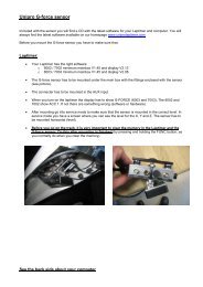
Laptimer <strong>5002</strong>A 5Temperature sensor (water): Mount the sensor in the cylinder head (M10x1) -alternatively on the cooling coil by a T-piece (additional equipment).ADDITIONAL EQUPMENTIR receiver: To be mounted under the front coat with strips or screws.Mount it on the left side of the cart in a horizontal position. The leans should be between200 mm and 500 mm above the ground level.On the IR receiver there are connection options for wheel sensor (measuring of speed) andloop receiver (i.e. you can use two receiver types at the same time (IR and loop).Intermediate boxAs an alternative to the IR receiver you can install an intermediate box, which also allowsconnection of loop receiver and wheel sensor (measuring of speed).Wheel sensor (measuring of speed):Sensor disc: To be mounted on the front wheel which is loaded the most. Take off thefront wheel in question. Place the centering bush in the inner ring of the front wheelbearing. Place the sensor disc over the sleeve and tighten it. Remove the centering bushand remount the front wheel.The wheel sensor: To be mounted on the steering knuckle. IT IS IMPORTANT that thedistance between the sensor disc (on the wheel) and the wheel sensor is between 2–8 mm.Before you enter the track, make sure that the wheel sensor is connected – see chapter 3under wheel circumference.
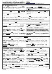
Laptimer <strong>5002</strong>A 6Temperature sensor (cylinder head): As an alternative to measuring the temperature ofthe water, you can measure the exhaust temperature. To mount the sensor you mustdemount the washer of the plug and take the plug through the sensor before the plug isremounted.Temperature sensor (exhaust): As an alternative to measuring the temperature of thewater, you can measure the exhaust temperature. Mount the sensor by welding theenclosed bush on to the exhaust manifold. The distance from the backside of the piston(exhaust gate) and the centre of the bush must be between 80-100 mm. When the bush ismounted, bore a 6 mm hole through the manifold. Place the sensor in the bush – app. 8-10mm down in the manifold - and fasten with the union.2. SETUP functions - listThe Laptimer has 8 main functions. When the Laptimer has been turned on by thePOWER button, the following data can be entered/read or stored.Enter the various functions by using the arrow buttonsSwift quickly by keeping one the of arrow buttons down.Display shows1. Press SETUP DELAY Lo Delay time Lo (1sec.-9.59 min.)2. Press SETUP DELAY Hi Delay time Hi (min Lo+10 sec. or OFF)3. Press SETUP POINT temp Max. temperature (25-600°C or OFF)4. Press SETUP EN. Hours of operation (engine No. 1-5)5. Press SETUP RECV. Receiver type (IR or loop)6. Press SETUP CIRC. Wheel circumference (0.6-2m or OFF)7. Press SETUP CONN. Type of connection (printer or PC)8. Press SETUP 2 STRO Type of engine (2 or 4 stroke)When data are entered they are ALWAYS stored when you exit the set-up function by theMODE button or by turning off by the POWER button or when the display turns offautomatically (after 5 minutes’ of torpor).BE AWARE that the display is turned off automatically after 5 minutes if there hasbeen no register of lap times, RPM or no button has been activated. This may have effectif e.g. a start is delayed.
Laptimer <strong>5002</strong>A 84. Hours of operation: By this function you can follow up to 5 engines’ total hours ofoperation. Hours of operation are measured as the time where signals have been receivedfrom the revolution sensor. The measured time is stored when you turn off the Laptimer bythe POWER button or the display turns itself off (after 5 minutes’ torpor).Enter the desired engine number by pressing the SETUP button until EN. 1 appears in thedisplay. Choose engine number 1 to 5 by using the arrow buttons.Go to the next set-up function by pressing the SETUP button or leave (and store) theentered data by pressing the MODE button.Choosing the actual engine number in the display and then press the black ring-buttonwill zero the time for the engine in question.5. Receiver type: Press the SETUP button until RECV. is shown in the display.Set the desired type of receiver (IR or loop) by using the arrow buttons.Go to the next set-up function by pressing the SETUP button or leave (and store) theentered data by pressing the MODE button.6. Wheel circumference. Press the SETUP button until CIRC appears in the display.Measure the circumference (in mm) on the wheel on which the sensor disc is mounted.Enter the measurement by using the arrow buttons. If you have not installed the wheelsensor or if you do not want to see the speed in the display choose CIRC OFF (600 + pressonce).Go to the next set-up function by pressing the SETUP button or leave (and store) theentered data by pressing the MODE button.The wheel circumference must be checked after every heat/test session and also if the tyrepressure has been changed. Enter new measurement, if any. This is important to ensurethat you get correct information on each lap.7. Type of connection:See the chapter about Printing out of data or the chapter about Transfer of data to a PC8. Type of engine:Press the SETUP button until 2/4 STRO appears in the display. Set the desired type ofengine by using the arrow buttons.Go to the next set-up function by pressing the SETUP button or leave (and store) theentered data by pressing the MODE button.
Laptimer <strong>5002</strong>A 10When you have finished going through your lap times etc., you turn off the Laptimer bypressing the POWER button or the Laptimer will turn itself off after 5 minutes (seechapter 2).When you turn your Laptimer on next time, it will automatically show the last lap stored.The Laptimer is ready to receive further signals from the transmitter.6. The memory of the Laptimer / deletion of dataThe Laptimer has a memory capacity of up to 1,000 laps!Stored data can be deleted in the following way. The Laptimer must be on.Press the POWER button until CLEAR LAPS appears in the display.All stored set-up functions are NOT deleted by above action7. Change of batteriesTwo 1.5V batteries size AA are required (must be alcaline batteries). (Duracell batteriesare recommended). Battery life is 60-80 hours depending on battery type/product.When you want to change batteries, loosen all cables. Remove the sheet at the back of themain box. Change batteries.Important: When replacing the sheet at the back of the main box, be sure it is placedcorrectly. Check that the mark in the rubber seal turns the right way.The Laptimer has indicators to show low power:• When the battery symbol appears in the display, it indicates low power (does notappear before the Laptimer bas been on for more than 10 sec.) .• When the symbol starts flashing, app. 10 minutes of operation remains.• When the complete display flashes, only 5 minutes of operation remains.Stored data are not lost at battery change!8. MaintenanceThe Laptimer can be used in all weathers. However, if you have been driving in rainyweather, the Laptimer should be dismantled after driving. Remove the back plate of thedisplay box and place all parts in a warm place for 24 hours. Then all parts can be reassembledand re-installed. Do not seal with liquid packing or with any other kind ofsealing compound.
Laptimer <strong>5002</strong>A 119. Printing out of dataIn order to print out the stored data, you need a Seiko DPU 414 or the like with printercable (is available at your dealer).Connect the printer cable to the printer and the Laptimer (at the under side) and turn theLaptimer on.Choose CONN PRINT in the set-up menu. Leave (and store) the entered data by pressingthe MODE button.Press the POWER button (if the Laptimer is not already on). Press the MODE buttontwice and the Laptimer is now in PRINTMODE.The order of options at the first printout:PR. SETUPPRINT ALLYou get a printout where you can enter the set-up of the cart,hours of operation and wheel circumferenceAll data are printed outThe order of options at the second printout:PR. LATESTPrints all data since the last printoutThis option is possible only after the first printout has been madeand therefore only shown from the second printout.When you have chosen the desired printout, start printing by pressing the ”ringbutton”.When data have been transmitted to the printer, the next option appears in the display. Youcan switch between the options mentioned above by pressing the SETUP button.On the printout a mark is shown every time the MODE button has be activated to indicatethat the Laptimer has been in pit-mode (the time when you have interrupted your training,a race or been in pit. The best time on each printout is marked with an asterix (*).
Laptimer <strong>5002</strong>A 1210. Transfer of data to a PCIn order to transfer the stored data to a PC, the programme on the enclosed disc must beinstalled.Insert the disc in the drive and choose RUN, choose “A:” in the start menu. Theprogramme can alternatively be copied into your PC if you wish.Choose the programme icon and the installation is started.Place the PC cable in the COM gate on the backside of the PC and in the Laptimer.(Choose the COM gate you use in the programme).Choose CONN PC in the set-up menu on the Laptimer. Leave (and store) the entered databy pressing the MODE button. Press the MODE button twice until the display shows PC 0SENT.The transmission is started when you press START on the tab TRANSFER. All data in theLaptimer have now been transferred to the PC and you can analyse, store or print out fromhere.Data can be stored in Excel as well where you have the option of making graphs andcurves as you wish.The use of the programme is obvious in each display in the various menus.
Laptimer <strong>5002</strong>A 1311. TroubleshootingThe Laptimer is switched on but does not register lap times:• Is the IR/loop transmitter switched on?• Is the IR/loop receiver placed horizontally and at the correct height?• Is the distance between the transmitter and the receiver correct (should be between2-3 metres)?• Is the battery power sufficient?• Does the Laptimer not receive a signal every time the transmitter/loop is passed?Check if the delay time is set too highThe Laptimer does not register the speed:• Check if the distance between the wheel sensor and the sensor disc is correct (2-8mm)Printing out is not successful• Press the SETUP button and check that CONN PRINT has been chosen• Check that the cable is correctly connectedTransfer to a PC does not work:• Check by pressing the SETUP button that CONN PC has been chosen• Check that the cable is correctly connectedYou are stuck and are not sure where in the programme you are:• Press the POWER button and turn the Laptimer off. Turn it on again by pressing thePOWER button and the Laptimer is back in “driving-mode”.The serial number is needed when you order spare partsYou find the serial number by pressing the SETUP button and the POWER button at thesame time. When the Laptimer is on let go of both buttons. The display now showsVER XXXX. Press the SETUP button once and the display will show SER XXXX =serial number.