
You also want an ePaper? Increase the reach of your titles
YUMPU automatically turns print PDFs into web optimized ePapers that Google loves.
<strong>Reference</strong> <strong>Manual</strong><br />
<strong>Unipro</strong> Laptimer<br />
7003<br />
Version 1.45<br />
15. March 2009<br />
Go faster faster<br />
UNIPRO ApS<br />
VIBORG HOVEDVEJ 24<br />
DK-7100 VEJLE<br />
DENMARK<br />
Tel.: +45 75 85 11 82<br />
Fax: +45 75 85 17 82<br />
www.uniprolaptimer.com<br />
mail@uniprolaptimer.com
Introduction ............................................................................................................................. 5<br />
General Information ................................................................................................................ 6<br />
History of <strong>Unipro</strong> .................................................................................................................................... 6<br />
Philosophy ............................................................................................................................................. 6<br />
Commonly used words .......................................................................................................................... 7<br />
Baud (bps) ................................................................................................................ 7<br />
Display ...................................................................................................................... 7<br />
DSP (digital signal processing) ...................................................................................... 7<br />
Filter ......................................................................................................................... 7<br />
First lap .................................................................................................................... 7<br />
Infrared .................................................................................................................... 7<br />
IrDA ......................................................................................................................... 7<br />
Logging ..................................................................................................................... 7<br />
Loop ......................................................................................................................... 7<br />
LEd Lamps ................................................................................................................. 8<br />
Magnet stripe ............................................................................................................. 8<br />
Main box ................................................................................................................... 8<br />
Memory .................................................................................................................... 8<br />
Processor .................................................................................................................. 8<br />
Protocol .................................................................................................................... 8<br />
Receiver .................................................................................................................... 8<br />
Trigger ...................................................................................................................... 8<br />
Telemetry .................................................................................................................. 8<br />
Receiver types ....................................................................................................................................... 9<br />
Loop (AMB) ............................................................................................................... 9<br />
Magnet (stripe) .......................................................................................................... 9<br />
IR (infrared) .............................................................................................................. 9<br />
Split types .............................................................................................................................................. 9<br />
Splits with magnet stripes ........................................................................................... 10<br />
Splits with wheel sensor ............................................................................................. 10<br />
Communication types .......................................................................................................................... 10<br />
Serial ....................................................................................................................... 10<br />
IrDA ........................................................................................................................ 10<br />
USB ......................................................................................................................... 11<br />
Laptimer functions ............................................................................................................... 12<br />
Turning Laptimer on............................................................................................................................. 12<br />
Turning Laptimer off............................................................................................................................. 12<br />
Clearing all ........................................................................................................................................... 12<br />
Low battery warning ............................................................................................................................ 13<br />
RPM calculation ................................................................................................................................... 13<br />
Speed measurement ........................................................................................................................... 14<br />
Instantaneous method ............................................................................................................................... 14<br />
Data stored .......................................................................................................................................... 15<br />
Logging ................................................................................................................................................ 16<br />
Analysing your data ............................................................................................................................. 17<br />
Data Analyser ........................................................................................................... 17<br />
PC Analyser .............................................................................................................. 17<br />
Laptimer Overview ................................................................................................................ 18<br />
UNIPRO – The original Laptimer 2
About the Display Unit ......................................................................................................................... 18<br />
How to use the display unit ................................................................................................................. 19<br />
Display buttons ......................................................................................................... 19<br />
The Main Box ....................................................................................................................................... 20<br />
Connectors ........................................................................................................................................... 20<br />
RPM ......................................................................................................................... 20<br />
WHEEL ..................................................................................................................... 20<br />
TEMP 1 .................................................................................................................... 21<br />
TEMP 2 .................................................................................................................... 21<br />
TEMP 3 .................................................................................................................... 21<br />
RECV 1 .................................................................................................................... 21<br />
RECV 2 .................................................................................................................... 21<br />
AUX ......................................................................................................................... 21<br />
USB ......................................................................................................................... 21<br />
DISP ........................................................................................................................ 21<br />
Installation ............................................................................................................................................ 22<br />
Display unit .............................................................................................................. 22<br />
Main box .................................................................................................................. 22<br />
RPM sensor ............................................................................................................... 25<br />
Receivers ................................................................................................................. 25<br />
AMB Loop receiver .................................................................................................................................... 25<br />
Magnet receiver ........................................................................................................................................ 26<br />
Infrared receiver ....................................................................................................................................... 26<br />
Temperature sensors ................................................................................................. 27<br />
Cylinder head sensor ................................................................................................................................. 27<br />
Exhaust sensor ......................................................................................................................................... 27<br />
Water sensor ............................................................................................................................................ 28<br />
Wheel sensor kit ........................................................................................................ 29<br />
The sensor disc ......................................................................................................................................... 29<br />
The wheel sensor ...................................................................................................................................... 30<br />
Laptimer setup ...................................................................................................................... 32<br />
Engine timers ....................................................................................................................................... 32<br />
Wheel circumference ........................................................................................................................... 33<br />
Tire wear counters ............................................................................................................................... 33<br />
Temperature inputs.............................................................................................................................. 34<br />
Temperature warning points ................................................................................................................ 34<br />
Shift light .............................................................................................................................................. 35<br />
Receiver type ....................................................................................................................................... 35<br />
Magnet setup ....................................................................................................................................... 35<br />
Magnet count ............................................................................................................ 36<br />
Magnet delay ............................................................................................................ 36<br />
Split points ........................................................................................................................................... 37<br />
Splits with magnet stripes ........................................................................................... 38<br />
Undo Clear split points! .............................................................................................. 38<br />
Splits with wheel sensor ............................................................................................. 39<br />
Viewing the split points .............................................................................................. 39<br />
Editing the split points ................................................................................................ 40<br />
Typical track with 6 split points ................................................................................................................... 40<br />
Display setup ....................................................................................................................................... 41<br />
Set left and right side of the lower part ......................................................................... 41<br />
Example with chosen information ................................................................................. 41<br />
UNIPRO – The original Laptimer 3
Minimum and maximum time between two trigs (retrig delay) ........................................................... 41<br />
Low delay ................................................................................................................. 41<br />
Display contrast ........................................................................................................ 42<br />
Display language ....................................................................................................... 43<br />
Setup in Service Mode ........................................................................................................................ 43<br />
Last data .................................................................................................................. 43<br />
Last temperatures ..................................................................................................................................... 43<br />
General information ................................................................................................... 43<br />
Lap length and theoretical best lap time ........................................................................ 44<br />
Laptimer statistics ..................................................................................................... 44<br />
Laptimer information .................................................................................................. 44<br />
Laptimer diagnostic .................................................................................................... 44<br />
Engine, RPM and speed measurement settings ............................................................... 45<br />
Laptimer setup – Communication ................................................................................. 45<br />
Laptimer setup - LED intensity ..................................................................................... 45<br />
Laptimer setup - Temperature ..................................................................................... 45<br />
Laptimer setup - speed type ....................................................................................... 45<br />
Laptimer setup - Off time ............................................................................................ 45<br />
Laptimer switches - Split light ..................................................................................... 46<br />
Split times display ..................................................................................................... 46<br />
Logger setup ............................................................................................................. 46<br />
Show at new lap ........................................................................................................ 46<br />
Software update ........................................................................................................ 46<br />
How to use the Laptimer in different operating modes ..................................................... 47<br />
Setup mode .......................................................................................................................................... 47<br />
Service Mode ....................................................................................................................................... 47<br />
Undo mode .......................................................................................................................................... 47<br />
First lap mode ...................................................................................................................................... 48<br />
Running mode ..................................................................................................................................... 49<br />
Pit mode ............................................................................................................................................... 50<br />
Normal data view ...................................................................................................... 50<br />
Graphical data view ................................................................................................... 50<br />
PC mode .............................................................................................................................................. 51<br />
Split measure mode ............................................................................................................................. 51<br />
Defining the split points with the use of the wheel sensor ................................................ 51<br />
Time run mode ..................................................................................................................................... 52<br />
Maintenance .......................................................................................................................... 53<br />
Changing batteries ............................................................................................................................... 53<br />
Updating ................................................................................................................................ 53<br />
Finding the current version .................................................................................................................. 53<br />
Update with a PC ................................................................................................................................. 54<br />
Trouble Shooting .................................................................................................................. 55<br />
The Laptimer is turned on, but do not register the lap time ................................................................ 55<br />
The Laptimer does not measure correct speed/split ........................................................................... 55<br />
The PC is reporting a none standard USB device plugged in! ........................................................... 55<br />
The RPM value is excessively high! .................................................................................................... 55<br />
UNIPRO – The original Laptimer 4
Introduction<br />
Thank you for trusting us to deliver the most advanced Laptimer on the market.<br />
This <strong>Manual</strong> includes detailed information about your <strong>Unipro</strong> Laptimer. If you need a quick<br />
overview of the functions, and a guide to the daily use, you may want to look at the QuickGuide<br />
first.<br />
The <strong>Unipro</strong> Laptimer has several unique features and will measure every piece of information with<br />
a speed and accuracy you have only dreamt about! It really enables you to use your Laptimer as a<br />
tool to go faster, faster.<br />
We did all we could to make your investment as future proof as possible and you should be able to<br />
enjoy it in many years to come. Therefore it is possible to expand the Laptimer with new<br />
accessories as they are being developed.<br />
If you have a special request either for new accessories or for a new feature, please let us know.<br />
We constantly try to develop our products with the most useful features so you can use the<br />
Laptimer to go faster, faster but we always appreciate good ideas from the users of our products.<br />
If you have any problems or questions regarding your <strong>Unipro</strong> Laptimer we will make sure to give<br />
you the necessary support.<br />
Please e-mail your questions to support@uniprolaptimer.com or contact your local dealer.<br />
Good luck on the tracks!<br />
UNIPRO ApS<br />
Viborg Hovedvej 24<br />
DK-7100 Vejle<br />
Denmark<br />
Web: www.uniprolaptimer.com<br />
E-mail: mail@uniprolaptimer.com<br />
UNIPRO – The original Laptimer 5
General Information<br />
History of <strong>Unipro</strong><br />
<strong>Unipro</strong> was founded in 1987 after inventing the world’s first Laptimer. It could only measure lap<br />
times and was produced in very small quantities. We still have one of the first six Laptimers<br />
produced and of course it is still working – after more than 20 years! In 1991 we did something<br />
people said couldn’t be done. We build the first Laptimer with RPM sensing integrated. This really<br />
helped the drivers to see how their engine was performing. In 1996, we made the first Laptimer<br />
with two temperature inputs and many other features not seen before. We made the unique split<br />
feature using a wheel sensor to divide the track into different segments (up to 9 segments), a<br />
digital signal processing of the RPM signal giving the most precise RPM value ever seen. You could<br />
even connect a portable, battery driven printer to the Laptimer and get all you valuable<br />
information on paper! In 2002, we decided to reinvent the <strong>Unipro</strong> Laptimer from scratch again!<br />
Your <strong>Unipro</strong> Laptimer is a result of this reinvention. We have made so many new inventions and<br />
features that we can’t get into them here, but now you really can use the Laptimer as a tool to go<br />
faster, faster!<br />
Philosophy<br />
People often ask us why we make Laptimers the way we do and we would like to tell you about<br />
our philosophy:<br />
Our top models will always have a separate display<br />
There are several positive sides and only one negative side to this:<br />
• It enables us to make an ultra thin display unit with a very appealing design<br />
• It will keep all the cables needed away from the steering wheel and thereby enable the<br />
driver to drive the kart!<br />
• It enables us to use two separated processors and keeping at lot of processing power free<br />
for the advanced calculations needed to give you the precise data we offer.<br />
• The only negative side about the separated systems is that the cost is higher!<br />
We will only make systems with enough buttons<br />
There are so many features at your fingertips, but if your Laptimer has to few buttons, it will be<br />
difficult to find the needed features fast enough. We will always make sure that the <strong>Unipro</strong><br />
Laptimer has enough buttons so it is fast and easy to operate.<br />
We use as much energy on the cables and sensors as on the Laptimer itself<br />
Every cable is hand built with the finest cable and finest connectors. We will not try to make<br />
money on spare parts that has to be replaced very often. We build every part of the Laptimer with<br />
the intention that it should never break!<br />
UNIPRO – The original Laptimer 6
Commonly used words<br />
Throughout this manual, we use many technical words and terms. In this section we will explain<br />
the most commonly used technical words.<br />
BAUD (BPS)<br />
Baud is another word for bit per seconds (bps). It tells you how many bits can be moved in a wire<br />
or in the air per second. Speeds of 115200 baud can in theory move 11520 bytes per second.<br />
Baud is used to measure serial speed, normally known from RS232.<br />
DISPLAY<br />
The display is also known as the LCD, monitor or screen.<br />
DSP (DIGITAL SIGNAL PROCESSING)<br />
Analogue signals are transformed into digital signals and then processed in a computer. This is<br />
called DSP and it can be done in a dedicated processor called a DSP or in a normal processor like<br />
the one used in the Laptimer. Using DSP algorithms, it is possible to do a lot of advanced<br />
processing.<br />
FILTER<br />
Remove something unwanted. One example of the use of filters in your Laptimer, is to remove<br />
unwanted noise when the RPM of your engine is measured.<br />
FIRST LAP<br />
The first part of the race. It is the segment from the pit to the finish line. It is sometimes called<br />
the out lap. This segment of the track is important because it is used to align the Laptimer to the<br />
finish line.<br />
INFRARED<br />
Invisible light beam in the infrared band. Normally just referred to as IR. The remote control for<br />
your TV or stereo also uses infrared light.<br />
IRDA<br />
Infrared Data Association. This is an infrared communication standard used in Laptops, PDAs,<br />
PalmPilots, mobile phones, printers and a lot more. The IrDA standard is both physical hardware<br />
and software.<br />
LOGGING<br />
Logging is storing data continues in a memory. The idea of logging is to store everything for later<br />
analysis – in the pit or on your PC.<br />
LOOP<br />
A Loop is a wire in the asphalt. The Loop is sending a signal that the Laptimer pick up every time<br />
it passes the loop. The Loop must be an active AMB Loop in order to trigger the Laptimer.<br />
UNIPRO – The original Laptimer 7
LED LAMPS<br />
A LED or Light Emitting Diode is a rather simple semiconductor circuit which emits light without<br />
producing waste heat. This means, it needs only very little energy, about 5% of a normal light<br />
bulb to produce the same amount of light. We use ultra bright LEDs as warning lamps in the<br />
display unit.<br />
MAGNET STRIPE<br />
A piece of magnet going all the way across the track. Used to trigger the Laptimer as an<br />
alternative to the loop.<br />
MAIN BOX<br />
Most of the electronic is located in the main box. This is the box with all the connectors, memory<br />
and batteries.<br />
MEMORY<br />
A lot of different memory is used for storing the program, setup, lap times and logged data. The<br />
most used type of memory is Flash or EEPROM. Both types are used in this Laptimer.<br />
PROCESSOR<br />
The part of the Laptimer with all the intelligence and calculating power. It is also called a CPU, μP,<br />
μC or just the computer.<br />
PROTOCOL<br />
A protocol is a piece of software that sets the standard for how the systems work. For example<br />
the process for sending data through infrared light is defined in the Infrared Data Association<br />
Protocol – the IrDA protocol.<br />
RECEIVER<br />
The receiver picks up the trigger signal and starts the Laptimers stopwatch. There are different<br />
types of receivers: loop, magnet stripe and infrared. Your <strong>Unipro</strong> Laptimer supports all kinds of<br />
receivers.<br />
TRIGGER<br />
The Laptimer trigs when it passes the finish line. The trigger can be either infrared light, a magnet<br />
stripe or a Loop signal.<br />
TELEMETRY<br />
A way of sending data through the air from the running kart to the pit. It is illegal during official<br />
races and can only be used for training.<br />
UNIPRO – The original Laptimer 8
Receiver types<br />
The <strong>Unipro</strong> Laptimer supports all kind of receivers. The different receivers are good for different<br />
things, and sometimes you need to change between several types. Unfortunately, none of them is<br />
perfect. We have made a short list of pros and cons of the different receiver types.<br />
LOOP (AMB)<br />
Very precise trig<br />
Long sensing distance.<br />
Full electronic systems without any problems at all.<br />
Not sensitive to vibrations.<br />
Use very little power in the Laptimer.<br />
AMB active Loop only. Will not work on a passive Loop.<br />
Sometimes the Loop is turned off.<br />
Only one on a track. Cannot be used for splits like several stripes.<br />
MAGNET (STRIPE)<br />
Very precise trig.<br />
Can have more than one on a track for splits.<br />
Use very little power in the Laptimer.<br />
Mechanical system.<br />
Can in worst case generate false trigs with excessive vibrations.<br />
IR (INFRARED)<br />
Can be used where no Loop or Magnets are present.<br />
Can be used far from the asphalt.<br />
Not as precise trig because the beam is spreading across the track.<br />
Can miss a trig if another driver is covering the infrared beam.<br />
Beam can hit the kart more than once on the track.<br />
Need an IR transmitter placed on the track.<br />
Use power in the Laptimer.<br />
<strong>Unipro</strong> recommends using the Loop receiver. This is the perfect receiver type if there is an active<br />
AMB Loop present at the track. Second choice is the Magnet receiver, but if you are at a race on a<br />
car park, the IR receiver is needed.<br />
Split types<br />
Dividing the track into smaller sections is one of the most important features of the Laptimer. It<br />
will help drivers at every level and in every type of kart to go faster, faster. There are two ways of<br />
using splits with your <strong>Unipro</strong> Laptimer:<br />
1. Splits with magnet stripes<br />
2. Splits with wheel sensor<br />
UNIPRO – The original Laptimer 9
SPLITS WITH MAGNET STRIPES<br />
If the track has more than one magnet stripe, it is possible to use the rest as split points. The<br />
problem with this method is that you do not have enough split points and you cannot place them<br />
yourself. You will no longer be able to view corner information because you typically have several<br />
corners per segment. Therefore you should only use the magnet stripes as split points if you are<br />
using a kart with four-wheel brakes.<br />
SPLITS WITH WHEEL SENSOR<br />
Using the high precision wheel sensor, you can define up to 8 points on the track as split points.<br />
This will divide the track in up to 9 segments giving you the possibility to optimize your kart setup<br />
and driving style for each segment of the track individually. You can set the splits in setup mode,<br />
during the first lap, wireless from the Data Analyser or using the USB cable from the PC Analyser<br />
program.<br />
Communication types<br />
An important feature of a Laptimer is the communication between the Laptimer and other devices.<br />
Typically you will use the Laptimer on the track for quick analysis, but if you want to go deeper<br />
into the analysis, you need to get the data away from the Laptimer to a PC or printer. This section<br />
describes the different communication standards.<br />
SERIAL<br />
Serial communications is normally referred to as RS232. It is a low speed, wire interface standard<br />
used in old Laptimers. RS232 is still used from the Data Analyser to the portable DPU printers, but<br />
the RS232 port is now removed from most modern Laptops. The speed typical ranges between<br />
9600 baud and 115.200 baud.<br />
IRDA<br />
IrDA is a shortcut for Infrared Data Association. It is a standard for communicating with invisible<br />
light. IrDA is a standard consisting of many levels. The lower ones describe the physical link. This<br />
is the one with use for communicating between the Laptimer and the Data Analyser. The physical<br />
speed is 115.200 baud, but because of overhead with error detections and retransmission, the<br />
real payload is around 75% of the theoretical limit.<br />
With the higher levels of the IrDA protocol, it is possible to communicate with PDAs, PalmPilots,<br />
Laptops, mobile phones and many other devices. It is possible to choose the full IrDA protocol in<br />
the Laptimer, enabling it to talk directly with a PDA. The higher levels add a lot of overhead, and<br />
it will lower the real speed of the transfer. The protocol is either a primary (master) or secondary<br />
(slave). <strong>Unipro</strong> uses a secondary protocol in the Laptimer and a primary protocol in the Data<br />
Analyser. The distance for an IrDA link is normally around 30 – 100 cm (10“ – 40“) but it is very<br />
depending on the surroundings. Fluorescent light and sun light will limit the possible range.<br />
UNIPRO – The original Laptimer 10
USB<br />
USB is a shortcut for Universal Serial Bus and is a pure PC standard. It is a high-speed serial link<br />
with two different speeds: USB 1.1 with a maximum speed of 12Mbps and USB 2.0 with a<br />
maximum speed of 480Mbps. The standard is divided into hosts (master) and devices (slave).<br />
Both the <strong>Unipro</strong> Laptimer and the Data Analyser are devices. In a system, a host is always needed<br />
and that is why it is not possible to connect the Laptimer to the Data Analyser using the USB<br />
cable! A future standard, called USB on the Go will combine the two things, enabling equipment to<br />
be both a host and a device.<br />
For none standard USB equipment to be used on a PC, a USB device driver is needed. The USB<br />
standard is a plug and play standard, and the PC will find new equipment when it is plugged into<br />
the USB port on the PC. The first time it will try to find a driver and install it. After that, you just<br />
plug the USB device in and out as you like, even with the power on.<br />
UNIPRO – The original Laptimer 11
Laptimer functions<br />
In this chapter we explain the basic functions of the Laptimer and the reason for why we have<br />
built it the way we have.<br />
Turning Laptimer on<br />
Turning the Laptimer on is done with the button.<br />
During power-on, the display will turn on all segments and<br />
the 5 LEDs will blink to show start-up is in progress.<br />
During the startup, the batteries are checked and the main<br />
box tries to communicate with the display unit. If they<br />
cannot find each other, the Laptimer turns off again.<br />
Turning Laptimer off<br />
To manually turn the Laptimer off, press and hold for<br />
more than one second. You will see the display go blank<br />
when the Laptimer is turning off.<br />
If no signal is present at the RPM input (engine stopped) the<br />
Laptimer will automatically be turned off after 5 minutes.<br />
Clearing all<br />
Clearing all data in the Laptimer is easy!<br />
Turn the Laptimer on an press the button for three<br />
seconds to clear all the data stored in the Laptimer. If this is<br />
done by accident, you can use UNDO mode to undo it again!<br />
ready to drive again.<br />
After doing clear laps, the Laptimer starts in firstlap mode<br />
No settings are cleared, only the laps and the logged data! We recommend clearing the Laptimer<br />
after each run. If you have too many laps in the Laptimer, it will get harder to analyse your data.<br />
Transfer the data to the Data Analyser or a PC before you clear the laps. Please remember, that<br />
the logged data can only be transferred to a PC, and not to the Data Analyser.<br />
UNIPRO – The original Laptimer 12
Low battery warning<br />
The Laptimer is constantly measuring the battery voltage and if the voltage drops too much, a<br />
battery-warning icon is shown in the display. There are three different warning levels before the<br />
Laptimer turns off:<br />
Indication Battery voltage What to do<br />
Turned on<br />
> 1.90 V<br />
This is an early warning. Do not change the<br />
batteries yet, but wait until the icon starts to<br />
blink. Batteries are expensive and not good for<br />
the environment. Please wait as long as possible.<br />
Blinks<br />
> 1.80 V<br />
Now it is time to change the batteries. When the<br />
icon starts to blink.<br />
Display blinks > 1.60 V<br />
This is the last chance to change the batteries<br />
without loosing any data.<br />
RPM calculation<br />
Different Laptimers have very different ways of calculating the RPM. The <strong>Unipro</strong> Laptimer use a<br />
very advanced method. The result is very precise calculation of the RPM. A very simplified<br />
explanation of the difference is that:<br />
<br />
Some Laptimers counts each pulse to the spark plug, and calculates a new RPM value for<br />
each 0.6 seconds – a total of 10 new RPM values per second.<br />
<strong>Unipro</strong> Laptimers use an advanced processor that measures the time between pulses to the<br />
spark plug. This method results in up to 350 new RPM values per second.<br />
<br />
Some Laptimers calculates the RPM without any kind of filter on the signal from the spark<br />
plug. Since there is a lot of unwanted noise, this method is not very precise.<br />
<strong>Unipro</strong> Laptimers uses an advanced two-way filter technology, of our own invention, to<br />
filter the signal from the spark plug. This method results in a very precise calculation.<br />
UNIPRO – The original Laptimer 13
Speed measurement<br />
The speed measurement is an important feature in the <strong>Unipro</strong> Laptimer. We have made our speed<br />
kit in a very high quality, in order to give you a precise measurement of:<br />
• Your speed, so you can see the effect on changes in your driving style or kart set-up<br />
• The tire wear<br />
• The lap length<br />
• The split points that divides the track into different sections<br />
The measurement of speed can be done in different ways. Some Laptimers use a method where<br />
the speed is calculated using the RPM combined with input about the gearing and wheel<br />
circumference. Other Laptimers counts the number of pulses from a wheel sensor in a certain<br />
amount of time, and then calculates the average speed during the period. The main disadvantages<br />
of both methods are that they are not very precise, and have a low update frequency. These<br />
methods are not very suitable for data logging.<br />
Instantaneous method<br />
The instantaneous method counts the time between pulses from a wheel sensor, and then<br />
calculates the speed at specific instants in time. We use this method in the <strong>Unipro</strong> Laptimer. Our<br />
wheel sensor has six pulses per wheel revolution, witch results in a very accurate speed<br />
measurement. The total precision is 0.48% from 0 to 350 KMH combined with a very fast update<br />
rate. The method is perfect for a real data logger and enables the PC Analyser program to do<br />
things like a slip graph showing you if the wheel is spinning or dragging and how much!<br />
The Slip-Distance graph shows the gearing on the left axis and the lap distance in the bottom. The<br />
gearing is the green line. Everything above the line is the rear wheel spinning and everything<br />
below the line is the rear wheel slipping or sliding. You can use this graph to compare your driving<br />
style from lap to lap, and learn where it is efficient with an aggressive driving style and where it<br />
isn’t. In order to make this graph you need a precise measurement of distance, speed and RPM.<br />
UNIPRO – The original Laptimer 14
Data stored<br />
During race or training the Laptimer stores a lot of information. All information are stored on both<br />
laps and splits. The Laptimer is capable of storing up to 2000 laps. However, if you use splits,<br />
each split will count as a lap because the same information is stored. If you are driving with 5 split<br />
points, you will get six split segments plus the total lap. Therefore the capacity is 2000 / 7 = 285<br />
laps.<br />
When you pass the finish line, or one of the split points, the following information is stored:<br />
• Lap time or split time. This value is between 0:00:00 and 10:55:35. Resolution is 1/100 th<br />
second.<br />
• Lap or split length. This value is between 0 and 8900 meters. Resolution is 1/6 th of the<br />
wheel circumference.<br />
• Min. and max. RPM. This value is between 0 and 35000 RPM. Resolution is 1 RPM. The min.<br />
and max. RPM are based on the filtered RPM signal and it is not related to the logging. The<br />
value is checked and stored for every pulse. That is up to 350 times per second!<br />
• Min. and max. speed. This value is between 0.0 and 350.0 KMH. Resolution is 0.1 KMH.<br />
• Min. and max. temp 1 and 2. This value is between 10.0 and 610.0°C. Resolution is 0.1°C.<br />
• Min and max. temp 3. This value is between 0.0 and 800.0°C. Resolution is 0.1°C.<br />
• Min. and max. temp 4-7. The values are between 0 and 127 degrees. Resolution is 1<br />
degree.<br />
• Environment temperature. The value is between 0.0°C and 51.0°C. Resolution is 0.2<br />
degree.<br />
• Engine number. This value is between 1 and 25.<br />
• Tire wear counter number. This value is between 1 and 8.<br />
• New run flag. This value is either true or false. A so-called flag is stored when you go into<br />
the pit. This will then enable the Data Analyser or PC program to calculate the run number.<br />
You can view all the stored data directly on your Laptimer, or you can transfer it to the Analyser,<br />
from the Analyser you can also print the data, in order to get a better overview of the data.<br />
Besides the data you can see directly on the Laptimer, even more detailed data are logged in the<br />
Laptimer memory so you can transfer it to a PC for further analysis. The logging is described in<br />
the next chapter.<br />
UNIPRO – The original Laptimer 15
Logging<br />
The <strong>Unipro</strong> Laptimer is a combined Laptimer and data logger. The difference between the two is<br />
that the Laptimer is ment to give you here and now information on the track and in the pit. The<br />
data logger stores even more information which enables you to transfer the data to a PC for<br />
further analysis. This gives you the opportunity to make comparisons that are much too complex<br />
to do just by browsing the Laptimer in the pit. The <strong>Unipro</strong> Laptimer is logging the following data:<br />
• Lap time. This value is between 0:00:00 and 10:55:35. Resolution is 1/100 th second.<br />
Stored 10 times per second.<br />
• Distance from finish line. This value is between 0 and 8900 meters. Resolution is 1/6 th of<br />
the wheel circumference. Stored 10 times per second.<br />
• Engine RPM. This value is between 0 and 35000 RPMs. Resolution is 1 RPM. Stored 10<br />
times per second.<br />
• Speed. This value is between 0.0 and 350.0 KMH. Resolution is 0.1 KMH. Stored 10 times<br />
per second.<br />
• Brake flag. This value is either true or false. Stored 10 times per second.<br />
• Temperature 1 and 2. This value is between 10.0 and 610.0°C. Resolution is 0.1°C. Stored<br />
1 time per second.<br />
• Temperature 3. This value is between 0.0 and 800.0°C. Resolution is 0.1°C. Stored 2 times<br />
per second.<br />
• Temperature 4-7. The values are between 0 and 127.0 degrees. Resolution is 0.1 degree.<br />
Stored 1 time per second.<br />
• Environment temperature. The value is between 0.0°C and 51.0°C. Resolution is 0.1<br />
degree. Stored 1 time per second.<br />
• Engine number used for the run. The value is between 1 and 25. Stored once per lap.<br />
• Tire wear counter used for the run. The value is between 1 and 8. Stored once per lap.<br />
• Number of temperature inputs used. The value is Temp 1-3 on/off. Stored once per lap.<br />
• Lap number. The value is between 1 and 1023. Store once per lap.<br />
<strong>Unipro</strong> offers a number of extra sensors, which are made with built-in processor and memory.<br />
When using any of these extra sensors the sensors must be connected to the laptimer when you<br />
transfer the logged data to your PC. Examples of extra sensors are G-Force, Lambda, Power<br />
valve, steering wheel, gas pedal and brake pedal.<br />
The logging is a background task and the logged data cannot be viewed on the Laptimer or on the<br />
Data Analyser. The data need to be transferred to the PC Analyser program for further analysis.<br />
In the 6002 and 6003 Laptimer there are memory enough to store 2 hours of data. In the 7002<br />
and 7003 Laptimer there are memory enough for almost 9 hours of data. With the USB cable you<br />
can easily transfer the data to a PC.<br />
UNIPRO – The original Laptimer 16
It is a common misunderstanding that you can use a program on a PC to filter out unwanted noise<br />
from the stored data. For instance the RPM will be calculated up to 350 times per second, but<br />
“only” stored 10 times per second. If the data aren’t filtered before it is stored the stored data will<br />
not be very accurate. That is one of the reasons why your <strong>Unipro</strong> Laptimer has a very advanced<br />
processor and a unique filtering technique.<br />
Analysing your data<br />
You can learn a lot about your performance on the track just from viewing the data on the display<br />
of the Laptimer. However if you want the full benefit of the Laptimer you should export the data<br />
from the Laptimer to a Data Analyser or to a PC. This will give you the possibility to print or store<br />
all data electronically, and to make advanced analysis of the data.<br />
DATA ANALYSER<br />
The <strong>Unipro</strong> Data Analyser is the perfect companion for your Laptimer. It is the fastest way to<br />
getting data out of the Laptimer, with the possibility to print the data, or view them while the<br />
driver is on the track.<br />
You can read more about using the Data Analyser in the manual for the Data Analyser.<br />
PC ANALYSER<br />
<strong>Unipro</strong> supplies a free software program called PC Analyser. This is a common platform to Analyse<br />
and manage data and sessions from a Laptimer and the Data Analyser.<br />
You can read more about using the PC Analyser in the manual for the PC Analyser.<br />
UNIPRO – The original Laptimer 17
Laptimer Overview<br />
This chapter is covering the basic overview of the Laptimer. We will go through the unit and the<br />
connectors so you can get familiar with the system.<br />
About the Display Unit<br />
The display unit is an ultra slim anodized aluminium casting. It is only 15 mm thick and only one<br />
cable is going to the main box from the steering wheel.<br />
Six buttons gives you quick access to all the functions. Five ultra bright LED Lamps are used for<br />
both temperature warnings and RPM shift light.<br />
IrDA is part of the display unit and enables wireless communication with the <strong>Unipro</strong> Data<br />
Analyser.<br />
The display unit has its own low power 16-bit processor to distribute the user interface from the<br />
main box to the display unit.<br />
The front of the display unit is completely sealed to make it waterproof. On the rear, a small hole<br />
is allowing the pressure introduced with temperature changes to escape and at the same time<br />
keep moisture out of the unit.<br />
UNIPRO – The original Laptimer 18
How to use the display unit<br />
We have put a lot of experience and effort into making the Display Unit very easy to operate on<br />
the track and in the pit. The feedback we get from drivers and teams using the <strong>Unipro</strong> Laptimer<br />
tells us that we have succeeded. Here you can get an overview over the functions on the Display<br />
Unit.<br />
DISPLAY BUTTONS<br />
SETUP<br />
Used for entering<br />
setup and service<br />
mode.<br />
Changes between<br />
min/max values in<br />
pit mode<br />
All the LEDs<br />
can be used<br />
as shift light<br />
SPLIT<br />
Change between<br />
splits and enter split<br />
measure mode with<br />
long press.<br />
Enter UNDO mode<br />
by holding it down at<br />
power-on.<br />
Temp 1<br />
warning<br />
Temp 3<br />
warning<br />
Temp 2<br />
warning<br />
Infrared<br />
communication<br />
IrDA<br />
UPPER<br />
LOWER<br />
MODE<br />
Press once to turn<br />
the Laptimer on.<br />
Hold it down to turn<br />
it off. Change<br />
between different<br />
modes.<br />
UP<br />
Adjust different<br />
values UP. Hold it<br />
down and to<br />
increase the speed<br />
of the adjustment.<br />
DOWN<br />
Adjust different<br />
values DOWN. Hold<br />
it down and to<br />
increase the speed<br />
of the adjustment.<br />
FUNCTION<br />
Enter Time Run Mode.<br />
Change values in upper<br />
display. Clear laps and<br />
more.<br />
UNIPRO – The original Laptimer 19
The Main Box<br />
The main box is where most of the processing takes place. The Laptimer has a powerful 16-bit<br />
processor and three different memories. The whole system is built with low energy components,<br />
which gives you the benefit of a very long lifetime on the battery. The main box with all the cables<br />
and connectors are placed behind the front cover and is only connected to the Display Unit with<br />
one single cable. This way you will not be troubled by a lot of cables on your steering wheel.<br />
Connectors<br />
The Laptimer has 9 high quality connectors plus the cable going to the connector on the Display<br />
Unit. This section will give a short overview over the different connectors and their purpose.<br />
! The names of the connectors are marked clearly on the Main Box. It is important that<br />
you only use the connectors for the purpose they are mend for.<br />
! Please use the rubber protection caps on connectors that are not in use. This will protect the<br />
connectors against water and dirt, and will ensure the correct operation of the Laptimer, even in<br />
rainy weather.<br />
RPM<br />
This 1-pin connector is for the RPM sensor only. It will work with our new active RPM sensor.<br />
Input range is 0 to 25000 RPM with a resolution of 1 RPM.<br />
WHEEL<br />
This 4-pin connector is for the speed sensor only. This is part of the speed kit and it is used to<br />
calculate speed, splits, lap lengths and more. Input range is 0 to 350 KMH with a resolution of 0.1<br />
KMH.<br />
UNIPRO – The original Laptimer 20
TEMP 1<br />
This 1-pin connector is for a PT1000 type temperature sensor. This is a high precision input used<br />
for water and cylinder head temperature. Input range is 10°C to 610°C with a resolution of 0.1°C.<br />
TEMP 2<br />
This 1-pin connector is for a PT1000 type temperature sensor. This is a high precision input used<br />
for water and cylinder head temperature. Input range is 10°C to 610°C with a resolution of 0.1°C.<br />
TEMP 3<br />
This 1-pin connector is for a NiCrNi type temperature sensor. This is a high temperature input<br />
used for exhaust temperature. Input range is 0°C to 800°C with a resolution of 0.1°C.<br />
RECV 1<br />
This 1-pin connector is for a Loop or Magnet receiver. This will be the typical way of triggering the<br />
Laptimer.<br />
RECV 2<br />
This 4-pin connector is for an IR receiver or other accessories. Used for IR receiver at present,<br />
this connector can be used for other accessories in the future like two-way Loop receiver,<br />
Telemetry and more.<br />
AUX<br />
This 4-pin connector is for extra sensors like G-force, Lambda, Power valve, etc.<br />
USB<br />
This 4-pin connector is for communication to a PC. This high-speed USB connection will transfer all<br />
the data in a few seconds.<br />
DISP<br />
This is the cable is going to the display unit. The connector is located at the other end!<br />
UNIPRO – The original Laptimer 21
Installation<br />
Your Laptimer is a precision instrument and you should take the necessary time to ensure correct<br />
installation. A basic rule is to start from the sensors and go back to the Laptimer, never the other<br />
way. If cables are too long, they should always be looped at the end near the Laptimer. Use<br />
plenty of strips to fix the cables to the frame.<br />
DISPLAY UNIT<br />
The Display Unit is mounted on the steering wheel. Due to the ultra thin Display Unit, you will not<br />
have any problems with regulations.<br />
Nut<br />
Metal washer<br />
Rubber washer<br />
Gray washer<br />
Steering wheel<br />
Rubber washer<br />
Display unit<br />
First, the Display Unit is mounted on the steering<br />
wheel. Choose a hole that gives a good placement at the<br />
top of the steering wheel. On some steering wheels, it is<br />
necessary to make the hole a little bigger.<br />
Remove the nut, the gray washer and one of the two<br />
black rubber washers. These parts are mounted on the<br />
back side of the steering wheel, as shown in figure 1.<br />
It is important to keep the right order of the washers.<br />
Please follow this sequence:<br />
Nut – metal washer – gray plastic washer – black rubber<br />
washer – steering wheel – black rubber washer – Display<br />
Unit.<br />
Tighten the nut when the display is strait and centered in the<br />
steering wheel. This picture shows the correct mounted<br />
Display Unit.<br />
MAIN BOX<br />
The main box is mounted behind the front cover. The following picture is showing the main box<br />
and its components.<br />
UNIPRO – The original Laptimer 22
Screw with washer<br />
Front cover<br />
Vibration damper<br />
Main box<br />
The main Box is mounted behind the front cover.<br />
First, a 6.5 mm hole is drilled in the cover. Some karts have a<br />
recess in the coat suitable for drilling the hole in. If you press<br />
hard on the sticker, you can see where to drill the hole. It is a<br />
good idea to look from the back before drilling!<br />
Use the enclosed umbracho screw<br />
The enclosed screw is screwed through the front coat to<br />
ease the mounting of the main box. Use a 6 mm<br />
umbracho.<br />
UNIPRO – The original Laptimer 23
Make sure that the cable for the Display Unit is pointing<br />
upwards.<br />
The Main Box is held with one hand and the umbracho screw is<br />
tightened with the other hand. The cable for the Display Unit must<br />
be pointing upwards. Make sure the box is placed straight before<br />
tighten the screw hard.<br />
The picture shows the Main Box after it is correctly mounted<br />
behind the front cover. With the Display Unit and the Main Box<br />
correctly mounted, you connect the Main Box and the Display<br />
Unit, and start to install the different sensors.<br />
Cable from the Main Box to the Display Unit.<br />
The cable for the Display Unit is now routed from the<br />
Main Box, along the steering column, to the connector on<br />
the Display Unit. Tighten the connector hard, but only<br />
use your fingers.<br />
Make sure the cable aren’t squeezed.<br />
It is very important that the cable cannot be squeezed,<br />
even at full swing of the steering wheel. Make a loop on<br />
the cable and strip it to the steering column. Test by<br />
turning the steering wheel all the way to both sides and<br />
feel if the cable at any points feels tight.<br />
UNIPRO – The original Laptimer 24
RPM SENSOR<br />
The RPM sensor comes standard with every <strong>Unipro</strong> Laptimer. We use an active sensor to ensure<br />
the best possible signal from all kind of engines. Mount the sensor with care. You do not want it to<br />
fall of during a race. If that happens, the Laptimer will turn itself off after 5 minutes and you will<br />
no longer be able to see your lap times.<br />
Mount the sensor with at least two strips.<br />
The RPM sensor is mounted in the middle of the ignition<br />
cable with at least two strips.<br />
The ignition on a gokart is the worst source of electrical<br />
noise and it is therefore a good idea to keep the RPM cable<br />
away from any other cables.<br />
Please do not let the RPM cable touch the cylinder or the<br />
cylinder head because it can tear the isolation and shield<br />
and cause disturbance. The most important issue is to<br />
separate the RPM cable from the ignition cable just after<br />
the sensor. This is clearly shown on the picture. Do not let<br />
the two cables run together!<br />
The cable is mounted in the connector marked RPM on the main box. Tighten the connector<br />
hard with your fingers.<br />
RECEIVERS<br />
The <strong>Unipro</strong> Laptimer supports all kind of receivers. The different receivers are good for different<br />
things. If the track has a loop, we recommend using the Loop Receiver.<br />
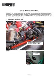
AMB Loop receiver<br />
Mounting the Loop receiver.<br />
The Loop receiver is mounted as low as possible on the left<br />
side of the seat. Drill a 6.5 mm hole from the inside of the<br />
seat. The distance from the underside of the Loop receiver to<br />
the asphalt must not exceed 100 mm.<br />
The Loop receiver is mounted parallel with the seat and needs<br />
to point backwards against the rear axle. Make sure, that<br />
nothing comes between the receiver and the track.<br />
Use plenty of strips to secure the cable to the Main Box.<br />
When the receiver is mounted, the cable is fixed to the middle of the kart, all the way to the<br />
Main Box. Use plenty of strips to secure the cable.<br />
The cable is mounted in the connector named RECV 1 on the Laptimer. Tighten the connector<br />
hard with your fingers.<br />
UNIPRO – The original Laptimer 25
Magnet receiver<br />
Mounting the magnet receiver.<br />
The best place to mount the magnet receiver is<br />
lengthwise on the bottom plate. Measure and drill the<br />
hole from the backside. The most important issue is to<br />
minimize the vibrations to the receiver. The most<br />
common placement of the magnet receiver is at the very<br />
front of the bottom plate, with the cable facing forward.<br />
The distance between the receiver and asphalt must not<br />
exceed 50 mm.<br />
Make sure that the cable is fixed properly.<br />
Lead the cable up on the back side of the front cover and into the<br />
Main Box. It is important that the cable is fixed properly. We<br />
recommend that you use strips to fix the cable to the front cover.<br />
The cable is mounted in the connector marked RECV 1 on the<br />
Main Box. Tighten the connector hard with your fingers.<br />
Infrared receiver<br />
Mounting the Infrared receiver.<br />
The best place to mount the infrared receiver is behind the<br />
front cover. Measure and drill the hole from the side. The<br />
most important issue is to mount the receiver horizontal.<br />
Remember to place the infrared transmitter at the same<br />
height as the infrared receiver at least 3 meters from the<br />
track.<br />
UNIPRO – The original Laptimer 26
Make sure that the cable is fixed properly.<br />
Lead the cable up on the back side of the front cover and<br />
into the Main Box. It is important that the cable is fixed<br />
properly. We recommend that you use strips to fix the<br />
cable to the front cover.<br />
The cable is mounted in the connector marked RECV 2 on<br />
the Main Box. Tighten the connector hard with your fingers.<br />
TEMPERATURE SENSORS<br />
On the 6002C/7002A it is possible to use up to three temperature sensors. Two of them (Temp 1<br />
+ 2) are using a standard which is limited in the temperature range, but has a very high<br />
precision. These inputs are used for the cylinder head sensor and water sensor. The last input<br />
(Temp 3) is able to measure very high temperatures, and can therefore be used for the exhaust<br />
sensor.<br />
Cylinder head sensor<br />
This is the cylinder head or plug sensor. There are different types, depending on your engine type.<br />
The cylinder head sensor must be use with the temperature 1 or 2 input.<br />
Remove the washer on your spark plug before mounting<br />
The ring for the sensor is mounted between the cylinder head and the<br />
spark plug. Use plenty of strips to secure the cable from the cylinder<br />
head to the Main Box. You may need different types if you use<br />
different engines. Ask you dealer or contact <strong>Unipro</strong> if you are in doubt.<br />
Mount the cable in the connector marked TEMP 1 or TEMP 2 on the<br />
Main Box. Tighten the connector hard with your fingers.<br />
Exhaust sensor<br />
The exhaust sensor is used to measure the temperature of the exhaust gas from the engine. It is<br />
important to mount it correctly, at the right position. If you mount the sensor to far away from<br />
the piston, you will measure temperature of the flame instead of the gas! Use only the TEMP 3<br />
input for the exhaust sensor!<br />
UNIPRO – The original Laptimer 27
Weld the bush on the exhaust pipe<br />
12-15 cm from the piston.<br />
The bush is mounted on the exhaust pipe.<br />
The distance should be 12-15 cm from the<br />
backside of the piston. Do not drill a hole<br />
in the exhaust pipe before you have<br />
welded the bush on the pipe.<br />
After the bush is welded on the exhaust<br />
pipe, drill a 4.1 mm hole in the middle of<br />
the bush through the exhaust pipe. Be<br />
careful not to damage the pipe on the<br />
other side when you drill through the<br />
pipe.<br />
Mount the sensor in the bush.<br />
After the hole is drilled, the sensor is<br />
pushed all the way in and tightened. Fix<br />
the cable to the seat, and all the way to<br />
the Main Box, so it is well protected.<br />
The cable is mounted in the connector<br />
named TEMP 3 on the Main Box. Tighten<br />
the connector hard with your fingers.<br />
Water sensor<br />
This is the sensor for measuring the water heat. Use either TEMP 1 or TEMP 2 for the water<br />
sensor. When you drive a kart with water cooled engine, the heat of the cooling water is of course<br />
important for the performance of the engine.<br />
UNIPRO – The original Laptimer 28
Mounting the water sensor.<br />
The water sensor is mounted on the hose that goes from<br />
the cooler to the engine. It is best to mount the sensor on<br />
the hose so the sensor sits near the seat, pointing<br />
downwards.<br />
Cut the hose in the right place and remember to put the<br />
two hose clamps on the two ends of the hose before<br />
inserting the T-junction in the hose.<br />
Tighten the two hose clamps to<br />
secure the T-junction in the right<br />
place.<br />
Mount the cable on the sensor<br />
and tighten it hard with your<br />
fingers. Then fix the cable with<br />
strips to the frame and lead it all<br />
the way to the Main Box.<br />
Mount the cable in the connector<br />
marked TEMP 1 or TEMP 2 on<br />
the Main Box. Tighten the<br />
connector hard with your fingers.<br />
WHEEL SENSOR KIT<br />
The wheel sensor kit is used for many of the advanced features in the Laptimer. For instance<br />
speed, splits, tire wear counters, lap length and more.<br />
The sensor disc<br />
The sensor disc is mounted on the front wheel with pressure on in most of the corners on the<br />
track. On most tracks this will be the left front wheel. But it is always best to count the corners of<br />
the track, and then choose the appropriate wheel.<br />
If you drive a kart with front wheel brakes, you will have to use a sensor disc specially made for<br />
mounting on the rear wheel axle. For this purpose you will also need a sensor with an extra long<br />
cable (this is automatically included if you order a complete speed kit for rear wheel mounting).<br />
UNIPRO – The original Laptimer 29
Dismount the wheel and put the centering bush in the<br />
inner ring of the bearing. If you drive with front wheel<br />
hubs, you must mount the sensor disc on the hub instead<br />
of on the wheel – the method is the same as shown here.<br />
The sensor disc is<br />
placed over the<br />
centering bush and it is<br />
held firmly down. Then<br />
tighten the three small<br />
screws that fixes the<br />
sensor disc to the<br />
wheel. Tighten the three<br />
screws hard, so the<br />
sensor disc doesn’t go<br />
loose when you’re<br />
driving.<br />
After the sensor disc is mounted, the centering bush is removed again. The wheel is now ready<br />
for mounting again.<br />
The wheel sensor<br />
The sensor fitting is mounted in a suitable hole in the<br />
stub axle. Depending on the kart model, it can be<br />
necessary to drill a hole in the stub axle.<br />
If you mount the fitting so the edge is 35-40 mm from<br />
the sensor disc, you will be able to make some<br />
adjustment on the sensor without having to move the<br />
fitting.<br />
Mount the sensor in the fitting so the distance between the sensor and the sensor disc is<br />
between 3 and 10 millimeters.<br />
UNIPRO – The original Laptimer 30
If you experience problems with the speed, this distance<br />
is the first thing to check!<br />
The cable is fixed to the frame in a nice large curve so<br />
the wheel can turn without the cable being caught or<br />
tightened.<br />
Remember to make the loop large enough to allow<br />
adjustment of the sensor when you change the front<br />
width of the kart.<br />
with your fingers.<br />
Fix the cable to the frame with strips all the way to the<br />
Main Box. The cable is mounted in the connector named<br />
WHEEL on the Main Box. Tighten the connector hard<br />
UNIPRO – The original Laptimer 31
Laptimer setup<br />
This will show you all the functions in setup mode. You get to setup mode by pressing<br />
you have turned on the Laptimer. You go from one setup to the next by pressing<br />
again.<br />
after<br />
When you get to the last setup, it will start again from the start when pressing<br />
Please note: All changes you make in setup mode is saved as soon as you have made the<br />
change. Just press the button to leave setup mode. It is made this easy because there are<br />
some settings you need to change every time you start a new run – training or race.<br />
Engine timers<br />
The Laptimer can store the run time of up to 25 different<br />
engines, each running up to 999 hours and 59 minutes.<br />
Before every training or race, you simply go to setup mode<br />
and choose the engine you are using, by using the<br />
and<br />
buttons to find the right engine number.<br />
If you should forget to choose the right engine timer before a training or a race, you can<br />
manually edit the timers. First, choose the right engine timer and then push . This will<br />
give you access to edit the minutes registered on the chosen engine timer. This is explained in<br />
the next step.<br />
You can use the and buttons to change minutes<br />
registered on the chosen engine timer. Each press will count<br />
one minute up or down. You can press<br />
to reset the<br />
timer. Close engine time edit by pressing .<br />
UNIPRO – The original Laptimer 32
Wheel circumference<br />
It is entered in millimetres and you need to measure this<br />
quite often to keep the system accurate. The best is to use a<br />
soft tape measure and do it every time you go out from the<br />
pit. It will have influence on the speed, the tire wear<br />
counters, and most important the split points.<br />
Adjust the circumference by using the<br />
buttons.<br />
and<br />
Tire wear counters<br />
The Laptimer can store the kilometres or miles of up to 8<br />
different sets of tire, each running up to 999 kilometres (or<br />
miles).<br />
Before every training or race, you simply go to setup mode<br />
and choose the tires you are using, by using the<br />
and<br />
buttons to find the right tire number.<br />
If you should forget to choose the right tire wear timer<br />
before a training or a race, you can manually edit the timers. First, choose the right tire<br />
number and then push . This will give you access to edit the kilometres or miles<br />
registered on the chosen tire wear counter. This is explained in the next step.<br />
You can use the and buttons to change the<br />
distance. Each press will count one kilometre up or down.<br />
You can press<br />
to reset the counter. Close again by<br />
pressing .<br />
Please notice: The icon is indicating a distance in meters. It<br />
is actually in kilometres (or miles).<br />
UNIPRO – The original Laptimer 33
Temperature inputs<br />
It is here you define how many temperature inputs you are<br />
using. Choose the right combination of the 3 temperature<br />
inputs. The reason to turn the inputs on or off is to save<br />
battery power and to adjust the user interface to the real<br />
setup.<br />
Use the and buttons to select the combination of<br />
temperature inputs you are currently using. You will only<br />
have to do this again if you add or remove temperature sensors.<br />
Temperature warning points<br />
Here you can define a warning point for each active<br />
temperature senson. The picture shows the setting of<br />
temperature point 1. Use the and buttons to<br />
adjust the temperature point. Temperatures are shown in<br />
either degrees centigrade or Fahrenheit. If you has activated<br />
more than one temperature sensor, you will go to the next<br />
warning point by pressing .<br />
Temperature point 1 is the left green LED, temperature point 2 is the right red LED and<br />
temperature point 3 is the middle yellow LED. They start to blink when the temperature<br />
rises above the warning point set.<br />
UNIPRO – The original Laptimer 34
Shift light<br />
The 5 LEDs at the top of the display can be used as gear<br />
shift indicators. In order to do that, you need to set two<br />
things. The first is the nominal RPM shift value, that means<br />
the RPM value where you want to shift gear. The other is the<br />
number of RPMs between the LEDs.<br />
The picture shows the nominal RPM shift value, in this case 14.5 kRPM. This is the value where<br />
the middle yellow LED is turned on. Depending on the value between the LEDs, the green LEDs<br />
to the left are turned on below this value and the red LEDs to the right are turned on above<br />
this value. Use the and buttons to adjust the RPM shift value.<br />
The RPM value between the LEDs is set in Service mode. If the RPM value between the LEDs is<br />
set to 2.0 kRPM, and the nominal value is set to 14.5 kRPM, it means that the green LEDs will<br />
turn on at 12.5 kRPM, the yellow LED at 14.5 kRPM, and the red LEDs at 16.5 kRPM. The RPM<br />
shift light is always using maximum brightness of the LEDs. Therefore, even if the intensity is<br />
turned down, the LEDs will be turned on at maximum intensity.<br />
Receiver type<br />
The <strong>Unipro</strong> Laptimer can use all types of receivers. You can<br />
choose between IR (infrared), Loop (AMB active loop) and<br />
magnet (magnet stripe in the track).<br />
Use the and buttons to choose the receiver type<br />
connected to the Laptimer.<br />
Magnet setup<br />
If the receiver type is set to Magnet this is the next step. It<br />
is the most important setup before you start driving on a<br />
new track. You need to set two values. The number of<br />
magnets from the pit to the finish line (1 in this example)<br />
and the total number of magnets on the track (4 in this<br />
example). See how to set the values in the next to screens.<br />
UNIPRO – The original Laptimer 35
MAGNET COUNT<br />
Set the total number of magnets on the track.<br />
When you press from the Magnet setup screen, you<br />
can edit the total number of magnets on the track. You can<br />
choose between 1 and 8 magnets. If you don’t know the<br />
number of magnets, you can set the Laptimer to use only<br />
one magnet and then drive one lap. Then you can see how<br />
many times the Laptimer triggers.<br />
Use the and buttons to adjust the total number of magnets.<br />
When the correct number of magnets are entered, press<br />
from the pit to the finish line (See the next screen).<br />
to edit the number of magnets<br />
MAGNET DELAY<br />
third one.<br />
Set the number of magnets from the pit to the finish<br />
line.<br />
This is the number of magnets you need to delay when going<br />
from the Pit to the finish line. In this example, you need to<br />
pass two magnets when going out from the Pit. This means,<br />
that on the out lap (or first lap) the Laptimer ignores the first<br />
two magnets and then start the Laptimer when passing the<br />
Use the and buttons to adjust the magnets delay.<br />
Press<br />
to save and return to the magnet setup screen.<br />
UNIPRO – The original Laptimer 36
Example on a typical track with three magnet stripes.<br />
This could be a<br />
problem if you<br />
go in & out of<br />
You go on<br />
the track<br />
<br />
<br />
You go<br />
into the<br />
pit here<br />
Laptimer need<br />
to skip this on<br />
the out lap!<br />
<br />
Correct place to<br />
trig the<br />
Laptimer, near<br />
As you can see, there are three different magnet stripes on this track. It is very important to start<br />
(trig) the Laptimer near the finish line, in this example that is magnet number 2. That means that<br />
when you are driving out from the pit, the first magnet need to be skipped or you need to delay<br />
the trig by one magnet.<br />
If you go into the pit and out on the track again, it is possible that you skip one of the magnets. If<br />
you shut the Laptimer down and turn it on again before going out on the track again, the laptimer<br />
will automatically start correctly again (Read more about this under Operating modes).<br />
Split points<br />
Dividing the track into smaller sections is one of the most important features of the Laptimer. It<br />
will enable you to see all data in the laptimer for each section of the track. There are two ways of<br />
using splits with your <strong>Unipro</strong> Laptimer:<br />
1. Splits with magnet stripes<br />
2. Splits with wheel sensor<br />
UNIPRO – The original Laptimer 37
SPLITS WITH MAGNET STRIPES<br />
If the track has more than one magnet stripe, it is possible to use the rest as split points. When<br />
you have made a correct stripe setup, as mentioned above, you just need to set the Laptimer to<br />
use the stripes as split points. The only problems are that you may not have enough split points,<br />
or you may want to have the split points in different places. You can solve these problems by<br />
using the wheel sensor to set the split points.<br />
Defining the split points with magnet stripes<br />
Make sure, that you have downloaded all data from the Laptimer before changing the<br />
split points. All laps will be cleared when you change the split points.<br />
Press<br />
Then press<br />
until you get to the split point viewing screen.<br />
to go to the split point editing screen.<br />
Press<br />
press<br />
until you get to the split magnet screen. Then<br />
to leave the editing screen, and save the setup.<br />
UNDO CLEAR SPLIT POINTS!<br />
If you by accident clear all laps by changing the split points you can undo the action this way:<br />
1. Turn the Laptimer off by pressing down for 3 seconds.<br />
2. Press and hold down while pressing once.<br />
3. When the display turns on, let go of the and you will be in Undo mode.<br />
4. Use or to change between YES and NO.<br />
5. Leave the text on YES and press to undo the action. The display will now turn of, and<br />
you are ready to start all over again.<br />
UNIPRO – The original Laptimer 38
SPLITS WITH WHEEL SENSOR<br />
Using the high precision wheel sensor, you can define up to 8 points on the track as split points.<br />
This will divide the track in up to 9 segments giving you the possibility to optimize your kart setup<br />
and driving style for each segment of the track individually. You can set the splits in setup mode,<br />
during the first lap, wireless from the Data Analyser or using the USB cable from the PC Analyser<br />
program.<br />
Defining the split points with the use of the wheel sensor<br />
When you define split points for a track the first time, the easiest way is to do as follows:<br />
1. Make sure that you have downloaded all data from the Laptimer. All laps will be erased<br />
when you set new split points.<br />
2. Decide where on the track you want to have the split points. It can be a good idea to start<br />
with just two or three split points, and then set more points when you have become<br />
familiar with analyzing the data.<br />
3. Get the kart and driver ready for driving a first lap where the split points are set.<br />
4. Turn the Laptimer on by pressing<br />
5. Press and hold down until the message “Clear Splts” is shown in the display.<br />
6. Now all laps and split points in the Laptimer are erased and you are ready to drive out and<br />
set the new split points.<br />
7. Every time you come to a split point, press to set the split pointWhen the first lap is<br />
driven, the Laptimer will automatically change to running mode.<br />
Each split point is measured in distance from the finish line, and stored in the Laptimer. You can<br />
use the stored data in different ways:<br />
a. You can write down the placement of the split points, so you can use the exact same split<br />
points next time you are driving on the same track.<br />
b. You can use the split point information to set the same split points on other Laptimers in<br />
the team.<br />
c. You can change the split points manually, if you are not satisfied with the placement.<br />
VIEWING THE SPLIT POINTS<br />
Press<br />
Then press<br />
until you come to the split point viewing screen.<br />
to see the different split points.<br />
In this example you can see that split point no. 1 is set at<br />
351 meters from the finish line. Press if you want to<br />
adjust the split points manually.<br />
UNIPRO – The original Laptimer 39
EDITING THE SPLIT POINTS<br />
Press from the split point viewing screen to edit the<br />
split points manually.<br />
Use to change the split number. Use and to<br />
change the distance from the finish line to the actual split<br />
point. Leave the split point editing screen again by pressing<br />
.<br />
Make sure that you leave the split point editing screen from the last split point you<br />
want to use. The split number shown in the display when you press<br />
total number of splits saved in the setup. You can set up to 8 split points.<br />
is going to be the<br />
Typical track with 6 split points<br />
<br />
<br />
<br />
<br />
<br />
<br />
Please be aware though, that the split function with the wheel sensor will not work well on a kart<br />
with four-wheel brakes because the sensor needs to be on a free running wheel! In that case, you<br />
must use a magnet receiver and the magnet stripes as split points.<br />
UNIPRO – The original Laptimer 40
Display setup<br />
The display is divided into an upper and lower part. In the display set-up you can define which<br />
values you want to show in the lower part during the race. The upper part of the display will<br />
always show RPM, Lap number and lap time. You can see more about this under “Running mode”.<br />
SET LEFT AND RIGHT SIDE OF THE LOWER PART<br />
Choose which information you want to see in the lower left<br />
side of the display during race (in running mode). Depending<br />
on the options enabled, you can choose between, Speed,<br />
RPM, Temp 1, Temp 2, Temp 3 or none. Use and<br />
to choose the information you want to see. If you want to<br />
see the hidden information during race, you can see them by<br />
pressing<br />
Use the same procedure for setting up the information shown in the lower right side of the<br />
display.<br />
EXAMPLE WITH CHOSEN INFORMATION<br />
This is an example of the display in running mode<br />
In this example Speed is chosen to be shown in the lower left<br />
side, and TEMP 1 is chosen to be shown in the lower right<br />
side.<br />
Minimum and maximum time between two trigs (retrig delay)<br />
LOW DELAY<br />
If you use a Loop or IR receiver, you can choose a minimum delay from one trig to the next. This<br />
is the minimum time allowed between two trigs. This is primarily used if an IR transmitter can<br />
reach across the track and then trigger the Laptimer more than once on the same Lap.<br />
UNIPRO – The original Laptimer 41
Laptimer<br />
triggers again!<br />
IR beam hits<br />
No problem.<br />
Receiver is facing<br />
other way!<br />
Correct trig<br />
of Laptimer<br />
Infrared<br />
transmitt<br />
To prevent the problem with IR receivers trigging more than<br />
once on a lap, set the Low Delay time to 2-5 second below<br />
the normal lap time. When this time is elapsed, the Laptimer<br />
turns on power to the IR receiver and enables the trigger<br />
again. When the Laptimer is trigged, it is turned off again.<br />
Adjust the delay time with and . The time is in<br />
minutes : seconds.<br />
When you set the delay time as close as possible to the normal lap time you will also get a<br />
longer lifetime of your battery, because the IR receiver will be turned off most of the time.<br />
DISPLAY CONTRAST<br />
Here you can adjust the screen contrast from +5 to -5.<br />
Adjust the contrast with and .<br />
UNIPRO – The original Laptimer 42
DISPLAY LANGUAGE<br />
Here you can choose the language of the display. Choose the<br />
language with and .<br />
Setup in Service Mode<br />
Service mode is where the functions and setup, which are not used very often are placed. You<br />
enter service mode by pressing and holding<br />
when turning the Laptimer on with a short push<br />
on the button. To exit the Service mode, press and hold down for 3 seconds, to turn<br />
the Laptimer off.<br />
LAST DATA<br />
The Laptimer has a unique feature called last data. Sometimes you are interested in the data on<br />
the last lap not finished. This is very useful if the engine crashes. With these features, you can go<br />
back and see exactly what happened.<br />
Last temperatures<br />
For all three temperature inputs, the temperature is stored<br />
at the split second when the engine stops. Therefore, if you<br />
have an engine crash you can see the three temperatures at<br />
that exact point in time when the engine stop and perhaps it<br />
will be clearer why it happened. Also the last RPM and the<br />
last speed is stored and shown on this screen.<br />
GENERAL INFORMATION<br />
Here you can see information about environment<br />
temperature, memory usage, battery voltage, battery status<br />
and battery lifetime. This screen is showing a real time view<br />
of these values.<br />
UNIPRO – The original Laptimer 43
LAP LENGTH AND THEORETICAL BEST LAP TIME<br />
You can view the lap length for each lap stored in the<br />
Laptimer. In the same screen, you can see the calculated<br />
theoretical best lap time, which is the time you get when all<br />
the best split times is added to make one theoretical lap. Use<br />
the and buttons to select the lap you want to<br />
view.<br />
LAPTIMER STATISTICS<br />
The Laptimer stores information about total time the<br />
Laptimer has been turned on, total number of laps, total<br />
distance and total number of times the Laptimer has been<br />
turned on. You can view these values on the Laptimer<br />
statistics screen.<br />
LAPTIMER INFORMATION<br />
On the Laptimer information screen, you can see the<br />
mainbox version, the display version, the Laptimer model,<br />
the serial number and the manufacturing date.<br />
LAPTIMER DIAGNOSTIC<br />
The Laptimer diagnostic screen has mainly information for<br />
service purpose. It will show the last error codes for errors<br />
from the main box and the display unit, and will show the<br />
total number of errors from the main box and the display<br />
unit.<br />
UNIPRO – The original Laptimer 44
ENGINE, RPM AND SPEED MEASUREMENT SETTINGS<br />
You can set the engine stroke between 1 and 8. RPM delta is<br />
the number of engine revolutions you want to have in the<br />
intervals if you use the shift light function. In this screen you<br />
can also set the number of magnets on the speed sensor disc<br />
to a different number than 6, which is the standard number<br />
of magnets on the <strong>Unipro</strong> sensor disc. Use<br />
and<br />
buttons to find the setting you want to change. Use<br />
to<br />
choose the desired setting, and use and to change the value. Confirm the chosen<br />
value with<br />
and you can move on to the next setting.<br />
LAPTIMER SETUP – COMMUNICATION<br />
Typical connection to the outside is either IrDA (infrared) or<br />
USB. If you set the Laptimer to use IrDA, it will go to PC<br />
mode after leaving pit mode. If it is set to use USB, it<br />
changes directly to PC mode when the USB cable is<br />
connected.<br />
You use IrDA to send the data to our handheld Data Analyser<br />
and USB to send data directly to a PC.<br />
For all editing in the Laptimer setup screen: Use and buttons to find the setting you<br />
want to change. Use to choose the desired setting, and use and to change the<br />
value. Confirm the chosen value with<br />
and you can move on to the next setting.<br />
LAPTIMER SETUP - LED INTENSITY<br />
The Laptimer has 5 ultra bright LED lamps at the top. Two green, 1 yellow and two red. You<br />
can adjust the intensity of the LEDS on a scale from 1 to 25. Even at full intensity, the LEDs<br />
use very little power, so it will not affect the battery life considerably.<br />
LAPTIMER SETUP - TEMPERATURE<br />
You can choose between temperature readout in Centigrade or Fahrenheit.<br />
LAPTIMER SETUP - SPEED TYPE<br />
You can choose between speed and distance readout suitable for your country. If you choose<br />
EU the readout are in meters and kilometers. If you choose US the readout are in inches and<br />
miles.<br />
LAPTIMER SETUP - OFF TIME<br />
In this screen you can set the time to go before the Laptimer is turned off automatically.<br />
UNIPRO – The original Laptimer 45
LAPTIMER SWITCHES - SPLIT LIGHT<br />
During the race you can use split lights to indicate if the last<br />
split time was faster, the same or slower as the best split<br />
time. If this feature is set to YES, the split lights will be<br />
shown right after passing each split point. The light will be<br />
green for a faster split, yellow for the same and red for a<br />
slower split time.<br />
For all editing in the Laptimer switches screen: Use and buttons to find the setting you<br />
want to change. Use to choose the desired setting, and use and to change the<br />
value. Confirm the chosen value with<br />
and you can move on to the next setting.<br />
SPLIT TIMES DISPLAY<br />
During the race, the Laptimer can show the split times. Normally only the lap time is<br />
displayed. If this option is set to YES, the Laptimer will update the display with the current split<br />
number and split time.<br />
LOGGER SETUP<br />
If you only wish to use the Laptimer as a Laptimer and not a data logger, you can disable the<br />
logger function here. If you do not want to analyse the data on a PC, you can turn off the<br />
loggers function to save power.<br />
SHOW AT NEW LAP<br />
Typical the Laptimer is set to show the difference between the current lap time and the best<br />
lap time when you pass the finish line. You can also choose to show the max. values for<br />
temperature, speed and RPM, or you can turn the function of so neither delta time or max.<br />
values are shown.<br />
SOFTWARE UPDATE<br />
It is easy to keep your Laptimer up to date with the latest features.<br />
All software updates from <strong>Unipro</strong> are free and they can be downloaded from our homepage.<br />
You will find the download from the product page. Then right click on the link and choose Save<br />
As and save the file to the hard disc on your PC.<br />
UNIPRO – The original Laptimer 46
How to use the Laptimer in different operating modes<br />
The Laptimer operates in different modes. There are following modes:<br />
• Setup mode<br />
• Service mode<br />
• Undo mode<br />
• Split measure mode<br />
• First lap mode<br />
• Running mode<br />
• Time run mode<br />
• Pit mode<br />
• PC mode<br />
Setup mode<br />
This is the mode where you change the settings of the Laptimer. Some of these settings need to<br />
be checked every time you start a new race or training. You enter setup mode by pressing<br />
from first lap mode, running mode, time run mode or PC mode. All the possible settings are<br />
explained in the chapter “Setup”.<br />
Service Mode<br />
Service mode is where the functions and setup, which are not used very often are placed. You<br />
enter service mode by pressing and holding<br />
when turning the Laptimer on with a short push<br />
on the button. To exit the Service mode, press and hold down for 3 seconds, to turn<br />
the Laptimer off.<br />
Undo mode<br />
When you change the settings you can choose to clear all information stored in the Laptimer. If<br />
you do so by accident, you can go to undo mode to restore the information. You must do this<br />
before starting a new race or training!<br />
This<br />
To<br />
is the undo screen.<br />
enter undo mode you must:<br />
1. Turn of the Laptimer by pressing and holding<br />
down<br />
2. Press and hold down while turning on the<br />
Laptimer with a single press on<br />
3. Move your finger from both buttons when the<br />
Laptimer starts.<br />
4. Use and to choose between YES and NO.<br />
5. Press when the display is showing YES to restore the information and NO if you<br />
don’t want to restore.<br />
UNIPRO – The original Laptimer 47
First lap mode<br />
This is the mode when the Laptimer is turned on. It is from the pit to the finish line for the first<br />
lap.<br />
When the Laptimer is turned on with the button, it<br />
starts up in firstlap mode. This is the part of the race going<br />
from the pit to the finish line for the first time.<br />
It will always start from the last lap shown in the Laptimer,<br />
so you will never “overwrite” anything when turning the<br />
Laptimer on. However, If you have looked at the lap times in<br />
pit mode, you must be careful to show the last lap before going onto the track again, since the<br />
Laptimer will start from the last shown lap when you come from Pit mode. You can also shut<br />
the Laptimer down (press Mode for 3 seconds) and the turn it on again before going to the<br />
track.<br />
If you are not in firstlap mode when the engine is started, the Laptimer will automatically<br />
change to firstlap mode when it detects a signal from the RPM sensor. This way, you cannot<br />
drive around in pit mode, and think you are getting lap times. It is however possible to change<br />
back to pit mode when the engine is running!<br />
The “-2-“ is telling how many magnets you need to pass before the finish line. This is the socalled<br />
stripe delay. It is possible to manual adjust this delay in firstlap mode. If driving with<br />
Loop or IR receiver, this part of the display is blank.<br />
When passing the finish line for the first time, the Laptimer change to running mode.<br />
UNIPRO – The original Laptimer 48
Running mode<br />
The Laptimer will automatically turn to running mode when you pass the finish line.<br />
When the finish line is passed for the first time, the display<br />
shows 0:00:00 to indicate that the timer is started.<br />
All data are updated in the display every 0.5 seconds. In the<br />
display set-up you can define which values you want to show<br />
in the lower part during the race. You can choose which data<br />
to show in the lower display with the<br />
button.<br />
The upper part of the display will always show RPM, Lap number and lap time. Small icons will<br />
help you identify the value shown. Indication of the best lap is done with the BEST icon above the<br />
lap time.<br />
When the Laptimer is passing the finish line, it is showing the<br />
difference between the current lap and the best lap and its<br />
position. In the shown example, the current lap is 8.98 seconds<br />
better than the previous best lap and the current lap is the best<br />
lap (in position 1) This information is shown for 5 seconds before<br />
changing back to data display. Only times between +/- 9.99<br />
seconds and positions from the 1st to 10th are shown<br />
UNIPRO – The original Laptimer 49
Pit mode<br />
After the race, you can view all the stored data in pit mode.<br />
NORMAL DATA VIEW<br />
Pit mode is for analysing the data stored in the Laptimer. If<br />
is pressed from either firstlap mode or running mode,<br />
you will enter pit mode.<br />
When entering pit mode, the Laptimer jumps to the best lap.<br />
In this example, the best lap is lap #18. From this point, you<br />
can go two ways: If you press<br />
you will go to the next<br />
lap (19 in this example). If you press the button, the Laptimer jumps to lap # 1.<br />
The BEST LAPTIME icon at the top indicates the best lap time. The<br />
button changes the<br />
data shown in the upper display.<br />
(minimum) data values stored.<br />
changes between the high (maximum) and the low<br />
When driving with splits, everything is stored on splits as<br />
well as laps. Use the button to toggle between all the<br />
splits stored in the Laptimer. This example shows the<br />
maximum data and the split time for split number 1.<br />
The segment from the last split point to the finish line is<br />
called split last. This split is marked L instead of a number.<br />
GRAPHICAL DATA VIEW<br />
On this screen you can scroll through the laps and see the<br />
current lap time, best lap time and the difference between<br />
the current and the best lap time well as laps. Together with<br />
the numbers there is a graphical view of the difference<br />
between current lap time and best lap time. Use<br />
and<br />
to scroll through the laps.<br />
UNIPRO – The original Laptimer 50
PC mode<br />
PC mode is for transferring the data from the Laptimer to the Data Analyser, a PC or something<br />
else.<br />
If the Laptimer is set to use USB, you will see this screen<br />
when the USB cable is connected. This shows the status of<br />
the USB link (PC icon on when USB cable is in) and after this<br />
you will choose Receive from the PC Analyser program to<br />
start the transmission. When the display shows “Finished”<br />
the transmission is finished.<br />
If the Laptimer is set to use IrDA or Analyser (infrared), the screen will be shown when<br />
pressing<br />
in pit mode.<br />
Press to enable the IrDA communication. The display will then change to the PC 0%<br />
SENT. Now you only need to point the Data Analyser to the display unit, and it will start to<br />
transfer the data wireless.<br />
Please notice, that the logged data is not transferred to the Data Analyser using IrDA. If you want<br />
to analyse the logged data, you need to transfer them with the USB cable.<br />
Split measure mode<br />
The split measure mode is used when you have the wheel sensor kit, and you want to set the split<br />
points while driving a round on the track. Draw the track on a piece of paper, mark the split points<br />
and then set them when driving a round on the track in split measure mode.<br />
DEFINING THE SPLIT POINTS WITH THE USE OF THE WHEEL SENSOR<br />
When you define split points for a track the first time, the easiest way is to do as follows:<br />
1. Make sure that you have downloaded all data from the Laptimer. All laps will be erased<br />
when you set new split points.<br />
2. Decide where on the track you want to have the split points. It can be a good idea to start<br />
with just two or three split points, and then set more points when you have become<br />
familiar with analyzing the data.<br />
3. Get the kart and driver ready for driving a first lap where the split points are set.<br />
4. Turn the Laptimer on by pressing<br />
5. Press and hold down until the message “Clear Splts” is shown in the display.<br />
6. Now all laps and split points in the Laptimer are erased and you are ready to drive out and<br />
set the new split points.<br />
7. Every time you come to a split point, press to set the split point When the first lap is<br />
driven, the Laptimer will automatically change to running mode.<br />
UNIPRO – The original Laptimer 51
The split points can then be duplicated on other Laptimers. The split points can also be entered<br />
manually in the Laptimer or can be transferred from the Data Analyser or the PC Analyser<br />
program. In the PC Analyser software there is a Split Point Wizard you can use to set the split<br />
points. This is a graphical way of setting the split points at the right places.<br />
Time run mode<br />
Time run mode is for breaking in new engines. This combines two functions:<br />
1. Hiding the lap times from the driver<br />
2. Start a stopwatch, showing the time driven with the engine<br />
Time run mode is entered by pressing and holding<br />
while turning the Laptimer on with a short press on .<br />
The display will show “RUN” in the display to indicate time<br />
run mode. This will be shown all the time in firstlap mode.<br />
When the finish line is passed for the first time, the display<br />
change to show the engine stopwatch. This stopwatch is<br />
running all the time the engine is started. No lap times or<br />
delta times will be shown during the practice. However all<br />
data is stored as usual, and can be viewed in pit mode. The<br />
engine stopwatch will start from zero when the Laptimer is<br />
changed to pit mode and back again.<br />
Turn the Laptimer off when you want to leave time run mode.<br />
UNIPRO – The original Laptimer 52
Maintenance<br />
How to keep the Laptimer up to date for many years.<br />
Changing batteries<br />
Even though you have a Laptimer with an extreme battery lifetime, eventual you have to change<br />
them! The batteries are located in the main box. Change them by following these steps:<br />
1. Dismount the Main Box from the kart – remove the connectors if necessary.<br />
2. Unscrew the four screws at the back of the Main Box and take off the lid<br />
3. Take out the two batteries and replace them with high quality Alkaline AA cells<br />
4. Make sure that the poles are in the right places – test it by turning on the Laptimer<br />
5. Put the lid back on – be sure to mount it in the same direction as it was before, so the<br />
sealing will give the best possible water protection<br />
6. Screw the four screws back in – don’t tighten them to hard<br />
7. Mount the connectors to the Main Box<br />
8. Mount the Main Box on the kart again<br />
Updating<br />
It is easy to keep your Laptimer up to date with the latest features. The Laptimer is user<br />
upgradeable and this section describes how to perform the upgrade.<br />
All software updates from <strong>Unipro</strong> are free and they can be downloaded from our homepage. You<br />
will find the download from the product page. Then right click on the link and choose Save as and<br />
save the file to your hard disc.<br />
Finding the current version<br />
Before updating the Laptimer, you will need to find the current version to see if there is an<br />
upgrade ready or not.<br />
First go to service mode with and and change to the Laptimer information screen with<br />
the button. This example shows a Laptimer with software version 1.33 in the main box and<br />
3.00 in the display unit. If you find a newer version on our homepage, you are ready to upgrade<br />
the Laptimer.<br />
UNIPRO – The original Laptimer 53
Update with a PC<br />
To be able to update the Laptimer with USB, you should first make sure you have a <strong>Unipro</strong> USB<br />
cable! This cable is necessary to upgrade the Laptimer. You should have installed the USB driver<br />
and the connection should be working before trying to update the Laptimer. It is easy to check the<br />
communication with the PC Analyser program and if you can transfer data from the Laptimer to<br />
the PC Analyser program, you are ready to go.<br />
Download the update program from uniprolaptimer.com and run the program from Windows.<br />
When starting the program you will see the following. Please select the language you prefer.<br />
When starting the program you will see the following. Please select the language you prefer.<br />
You just need to go through 8 simple steps to<br />
upgrade the Laptimer. The button will change<br />
when you are ready to go to the next step.<br />
When getting to step 6, you are updating the<br />
Laptimer and can only sit back and relax for 1<br />
minute while the update is going on.<br />
When the update is finished and you turn on<br />
the Laptimer again a message will be shown<br />
in the display. This should be FLASHED<br />
indicating that the Flash memory is<br />
programmed. After this message is displayed,<br />
you will see the display go blank for a 1<br />
second before going to firstlap mode. In this<br />
short delay, the two update programs may be<br />
updated.<br />
Please try to keep your Laptimer up to date to ensure optimal performance.<br />
UNIPRO – The original Laptimer 54
Trouble Shooting<br />
Here are the answers to som frequently asked questions. If you have any problems or questions<br />
regarding your <strong>Unipro</strong> Laptimer we will make sure to give you the necessary support.<br />
Please e-mail your questions to support@uniprolaptimer.com or contact your local dealer.<br />
The Laptimer is turned on, but do not register the lap time<br />
• Is the IR/Loop transmitter turned on?<br />
• Is the IR/Loop receiver placed horizontal and in the right height?<br />
• Is the receiver connecter tightened?<br />
• Did you choose the right receiver type in setup mode?<br />
• Is the magnet receiver placed lengthwise?<br />
• Is the distance between the IR transmitter and receiver correct (> 2 meters)<br />
• Do the Laptimer not receive a signal every time the transmitter/Loop is passed? Then<br />
check to see if the delay time is set to high. You need to set this a little below the fastest<br />
lap time.<br />
The Laptimer does not measure correct speed/split<br />
• Check if the distance between the wheel sensor and the sensor disc is correct (3 – 10<br />
mm)?<br />
• Are all six magnets still in the sensor disc?<br />
The PC is reporting a none standard USB device plugged in!<br />
• This is typical a problem because you did not plug the USB cable into the right connector<br />
on the Laptimer! Typical you did insert it into the AUX connector or RECV 2 connector<br />
instead!<br />
The RPM value is excessively high!<br />
• Check the stroke settings in setup mode. Perhaps you adjusted it down to 1-stroke?<br />
UNIPRO – The original Laptimer 55