Adjustable Fractional-Delay FIR Filters Using the ... - IEEE Xplore
Adjustable Fractional-Delay FIR Filters Using the ... - IEEE Xplore
Adjustable Fractional-Delay FIR Filters Using the ... - IEEE Xplore

You also want an ePaper? Increase the reach of your titles
YUMPU automatically turns print PDFs into web optimized ePapers that Google loves.
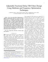
<strong>Adjustable</strong> <strong>Fractional</strong>-<strong>Delay</strong> <strong>FIR</strong> <strong>Filters</strong> <strong>Using</strong> <strong>the</strong><br />
Farrow Structure and Multirate Techniques<br />
Håkan Johansson, Oscar Gustafsson, Kenny Johansson, and Lars Wanhammar<br />
Division of Electronics Systems, Department of Electrical Engineering, SE-581 83 Linköping University, Sweden<br />
Email: hakanj@isy.liu.se, oscarg@isy.liu.se, kennyj@isy.liu.se, larsw@isy.liu.se<br />
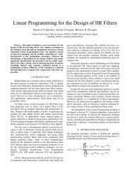
Abstract — The Farrow structure can be used for efficient<br />
realization of adjustable fractional-delay finite-length impulse<br />
response (<strong>FIR</strong>) filters, but, never<strong>the</strong>less, its implementation<br />
complexity grows rapidly as <strong>the</strong> bandwidth approaches <strong>the</strong> full<br />
bandwidth. To reduce <strong>the</strong> complexity, a multirate approach<br />
can be used. In this approach, <strong>the</strong> input signal is first interpolated<br />
by a factor of two via <strong>the</strong> use of a fixed half-band linearphase<br />
<strong>FIR</strong> filter. Then, <strong>the</strong> actual fractional-delay filtering<br />
takes place. Finally, <strong>the</strong> so generated signal is downsampled to<br />
retain <strong>the</strong> original input/output sampling rate. In this way, <strong>the</strong><br />
bandwidth of <strong>the</strong> fractional-delay filter used is halved compared<br />
to <strong>the</strong> overall bandwidth. Because <strong>the</strong> complexity of halfband<br />
linear-phase <strong>FIR</strong> filter interpolators is low, <strong>the</strong> overall<br />
complexity can be reduced. In this paper, we present more<br />
implementation details, design trade-offs, and comparisons<br />
when <strong>the</strong> filters are implemented using multiple constant multiplication<br />
techniques, which realize a number of constant multiplications<br />
with a minimum number of adders and<br />
subtracters.<br />
x(n)<br />
E L (z)<br />
d<br />
E 2 (z)<br />
I. INTRODUCTION<br />
This paper considers adjustable fractional delay (FD) filters<br />
which are required in several different applications [1]–[4].<br />
An efficient structure for adjustable FD filtering is <strong>the</strong> so<br />
called Farrow structure [5]–[7] which makes use of a number<br />
of fixed <strong>FIR</strong> subfilters and only one variable parameter<br />
(d) as seen in Fig. 1. The implementation complexity is<br />
<strong>the</strong>refore much lower for Farrow-based filtering methods<br />
than for methods based on ei<strong>the</strong>r on-line design or storage of<br />
a (huge) amount of different impulse responses.<br />
However, even if <strong>the</strong> complexity of <strong>the</strong> Farrow structure<br />
is relatively low, it grows rapidly as <strong>the</strong> bandwidth of <strong>the</strong> FD<br />
filter approaches <strong>the</strong> full bandwidth π [6], [7]. To reduce <strong>the</strong><br />
complexity, a multirate approach was proposed in [8]–[11].<br />
In this approach, <strong>the</strong> input signal is first interpolated by a<br />
factor of two via <strong>the</strong> use of a half-band linear-phase <strong>FIR</strong> filter.<br />
Then, <strong>the</strong> actual FD filtering takes place. Finally, <strong>the</strong> so<br />
generated signal is downsampled to retain <strong>the</strong> original input/<br />
output sampling rate. In this way, <strong>the</strong> bandwidth of <strong>the</strong> FD<br />
filter used is halved compared to <strong>the</strong> overall bandwidth.<br />
Because <strong>the</strong> complexity of half-band linear-phase <strong>FIR</strong> filter<br />
interpolators is low, <strong>the</strong> overall complexity can be reduced.<br />
For a bandwidth of 0.9π, savings of some 30-50% were<br />
reported in [10].<br />
In this paper, we present more implementation details,<br />
design trade-offs, and comparisons when <strong>the</strong> filters are<br />
implemented using multiple constant multiplication (MCM)<br />
techniques, which realize a number of constant multiplications<br />
with a minimum number of adders and subtracters.<br />
Following this introduction, Section II recapitulates <strong>the</strong><br />
basics of Farrow-based FD <strong>FIR</strong> filters and half-band linearphase<br />
<strong>FIR</strong> filters. Sections III and IV describe <strong>the</strong> multirate<br />
approach and <strong>the</strong> principles of MCM techniques. Section V<br />
presents comparisons between <strong>the</strong> original Farrow structure<br />
and <strong>the</strong> new one when <strong>the</strong> filters are implemented using<br />
MCM techniques. Finally, Section VI concludes <strong>the</strong> paper.<br />
II. FARROW-BASED ADJUSTABLE FD FILTERS AND<br />
HALF-BAND FILTERS<br />
A. Farrow-Based FD <strong>FIR</strong> <strong>Filters</strong><br />
Let <strong>the</strong> desired frequency response H des ( e jωT ) of an<br />
adjustable FD filter be<br />
H des ( e jωT ) = e – jD ( + d)ωT<br />
(1)<br />
= e – jDωT e – jdωT , ωT ≤ ω c T < π<br />
where D and d are fixed and adjustable real-valued constants,<br />
respectively. It is assumed here that D is ei<strong>the</strong>r an<br />
integer, or an integer plus a half, whereas d takes on values<br />
in <strong>the</strong> interval [– 1⁄<br />
2,<br />
1⁄<br />
2]<br />
. In this way, a whole sampling<br />
interval is covered by d, and <strong>the</strong> fractional delay equals d<br />
(d+0.5) when D is and integer (an integer plus a half).<br />
The ideal filter response in (1) can be approximated<br />
using <strong>the</strong> Farrow structure depicted in Fig. 1. The transfer<br />
function is <strong>the</strong>n expressed as<br />
where E k ( z)<br />
are <strong>FIR</strong> subfilters. Fur<strong>the</strong>r, it is possible and<br />
efficient (due to <strong>the</strong> coefficient symmetry) to impose linearphase<br />
constraints on <strong>the</strong> subfilters [5]–[7]. Consequently, we<br />
assume that each E k ( z)<br />
is an N G th-order linear-phase <strong>FIR</strong><br />
filter with ei<strong>the</strong>r a symmetric (for k even) or an anti-symmetric<br />
(for k odd) impulse response. Fur<strong>the</strong>rmore, it has<br />
been demonstrated that it is beneficial, in terms of implementation<br />
complexity, to make use of subfilters of unequal<br />
orders instead of equal orders [7]. To keep <strong>the</strong> notation simple,<br />
this is here taken care of by assuming that N =<br />
max{N k }, N k denoting <strong>the</strong> subfilter order, and introducing<br />
d<br />
E 1 (z)<br />
Figure 1. Farrow structure.<br />
L<br />
∑<br />
Gz ( ) = d k E k ( z)<br />
k = 0<br />
d<br />
E 0 (z)<br />
y(n)<br />
(2)<br />
1-4244-0387-1/06/$20.00 c○2006 <strong>IEEE</strong><br />
1055
additional delays to make all branches have <strong>the</strong> same delay.<br />
The filter with a transfer function in <strong>the</strong> form of (2) can<br />
approximate <strong>the</strong> ideal response (1) as close as desired by<br />
choosing L and designing <strong>the</strong> filter appropriately [6], [7].<br />
x(n)<br />
2 H(z) 2<br />
y(n)<br />
B. Half-Band <strong>FIR</strong> <strong>Filters</strong><br />
For a half-band <strong>FIR</strong> filter F(z) every second impulse<br />
response value is zero except for <strong>the</strong> centre tap that equals<br />
1/2, i.e.,<br />
fn ( )<br />
=<br />
⎧<br />
⎪<br />
⎨<br />
⎪<br />
⎩<br />
1 ⁄ 2, n = N F ⁄ 2 = K<br />
0, n = 13… , , , N F – 1,<br />
n ≠ N F ⁄ 2<br />
. (3)<br />
where K is half <strong>the</strong> filter order and an odd number. This<br />
means that <strong>the</strong> transfer function can be written as [12], [13]<br />
F 0 ( z 2 ) + z – K<br />
Fz ( ) = ------------------------------ . (4)<br />
2<br />
It is noted that (4) is a special case of a general polyphase<br />
decomposition [13] Fz ( ) = F 0 ( z 2 ) + z – 1 F 1 ( z 2 ) for<br />
F 1 ( z) = z– ( K – 1) ⁄ 2 ⁄ 2 . Fur<strong>the</strong>rmore, F 0 ( z)<br />
is a Type II<br />
linear-phase <strong>FIR</strong> filter of odd order K [12], which implies<br />
that <strong>the</strong> overall filter Fz ( ) becomes a Type I linear-phase<br />
<strong>FIR</strong> filter of even order N F = 2K.<br />
III. MULTIRATE APPROACH<br />
In <strong>the</strong> multirate approach for realizing FD filters, seen in<br />
Fig. 2, <strong>the</strong> input signal is first upsampled by a factor of two,<br />
<strong>the</strong>n filtered through a fractional-delay filter Hz ( ) , and<br />
finally downsampled by a factor of two. The desired overall<br />
fractional delay D+d is obtained by letting <strong>the</strong> delay of <strong>the</strong><br />
FD filter between <strong>the</strong> upsampler and downsampler be<br />
2(D+d). This is because <strong>the</strong> filter works at twice <strong>the</strong> input/<br />
output rate.<br />
However, in <strong>the</strong> final realization, all filtering takes place<br />
at <strong>the</strong> lower sampling rate. In addition, although multirate<br />
techniques are utilized, <strong>the</strong> arrangement in Fig. 2 is in fact a<br />
linear and time-invariant system with <strong>the</strong> transfer function<br />
being <strong>the</strong> 0th polyphase component of H(z) [13], i.e., H 0 (z)<br />
in <strong>the</strong> polyphase representation<br />
Hz ( ) = H 0 ( z 2 ) + z – 1 H 1 ( z 2 ) . (5)<br />
This is because <strong>the</strong> overall transfer function of <strong>the</strong> structure<br />
in Fig. 2 can be written as 0.5[ Hz ( 1 ⁄ 2 ) + H( – z 1 ⁄ 2 )]<br />
which<br />
equals H 0 (z). Here, H(z) is a cascade 1 of <strong>the</strong> FD and HB filters<br />
considered in Section II, i.e.,<br />
Hz ( ) = Fz ( )Gz ( )<br />
(6)<br />
which gives us <strong>the</strong> polyphase component H 0 (z) as<br />
H 0 ( z) = F 0 ( z)G 0 ( z) + z – 1 F 1 ( z)G 1 ( z)<br />
. (7)<br />
The delay of H 0 (z) is D+d = (D H +d H )/2 where D H +d H is <strong>the</strong><br />
delay of H(z). The fixed part D H is given by D H = N G /2+K<br />
1. We may also add an additional (positive or negative) delay in order to<br />
avoid half-integer delays [10], [11] but this is not considered in this paper.<br />
x(n)<br />
H 0 (z)<br />
Figure 2. Principle of multirate (two-rate) FD filtering approach.<br />
<br />
<br />
<br />
<br />
<br />
<br />
Figure 3. Multirate-based FD filter structure.<br />
With G(z) and F(z) in <strong>the</strong> form of (2) and (4), Structure 1 can<br />
be implemented as shown in Fig. 3 where E k0 ( z)<br />
and<br />
E k1 ( z) are <strong>the</strong> polyphase components of E k ( z)<br />
.<br />
The advantage of this structure is that it is fixed. This<br />
makes it suitable for applications where <strong>the</strong> fractional delay<br />
d changes from sample to sample (or at least frequently). The<br />
(minor) disadvantage is that <strong>the</strong> variable fractional delay at<br />
<strong>the</strong> higher rate, i.e., d H , must cover <strong>the</strong> interval [– 1,<br />
1]<br />
when<br />
<strong>the</strong> desired overall variable fractional delay d H covers<br />
[– 1⁄<br />
2,<br />
1 ⁄ 2]<br />
. The wider this range is, <strong>the</strong> higher will <strong>the</strong> filter<br />
order of <strong>the</strong> fractional delay filter G(z) be. But <strong>the</strong> overall<br />
complexity can despite of this fact be lower than that of a<br />
regular Farrow-based FD filter [10], [11].<br />
Is is worth pointing out that <strong>the</strong> complexity can be<br />
reduced even fur<strong>the</strong>r by also utilizing <strong>the</strong> two optional structures<br />
obtained by adding a positive and negative delay to<br />
H(z) in (6) [10], [11]. By switching between <strong>the</strong> three different<br />
structures appropriately, one can make <strong>the</strong> interval for d H<br />
become [– 1⁄<br />
2,<br />
1 ⁄ 2]<br />
, which reduces <strong>the</strong> complexity of <strong>the</strong><br />
Farrow-based FD filter. The disadvantage is that, due to <strong>the</strong><br />
switching between <strong>the</strong> two different structures, <strong>the</strong> implementation<br />
becomes more complex if one wants to avoid transient<br />
problems. This case is <strong>the</strong>refore more attractive for<br />
applications where <strong>the</strong> fractional delay d does not change too<br />
often. Due to a lack of space, this alternative will not be discussed<br />
fur<strong>the</strong>r in this paper.<br />
IV. MULTIPLE CONSTANT MULTIPLICATION TECHNIQUES<br />
For dedicated hardware implementations, one can take<br />
advantage of multiple constant multiplication (MCM) techniques<br />
to reduce <strong>the</strong> implementation cost. Multiplications by<br />
constant coefficients can be performed using adders, subtracters,<br />
and shifts. As adders and subtracters have approximately<br />
<strong>the</strong> same implementation complexity we will<br />
henceforth refer to both as adders. Efficient realization of<br />
constant multiplications is an active research area and much<br />
effort has been laid on <strong>the</strong> case where one input data is multiplied<br />
by several constant coefficients. This problem has<br />
mainly been motivated by single-rate <strong>FIR</strong> filters, where for a<br />
transposed direct form <strong>FIR</strong> filter <strong>the</strong> input is multiplied by<br />
several coefficients [14]–[18]. The resulting implementation<br />
y(n)<br />
<br />
<br />
<br />
<br />
<br />
<br />
1056 APCCAS 2006
Figure 4. Realization of Farrow filter using transposed direct form<br />
subfilters resulting in a multiplier block and several sets of registers.<br />
<br />
of several multiplications is denoted multiplier block [14].<br />
Work has also been done for sampling rate change with<br />
an integer factor in [19], where it was shown that <strong>FIR</strong> filters<br />
in parallel can be implemented ei<strong>the</strong>r using one multiplier<br />
block or by using a constant matrix multiplication block<br />
[21]–[23], with <strong>the</strong> first approach requiring more delay elements<br />
than <strong>the</strong> latter. As a Farrow filter also is composed of<br />
several <strong>FIR</strong> filters in parallel we have <strong>the</strong> same implementation<br />
alternatives here, not only <strong>the</strong> single multiplier block<br />
case as reported in [20]. In Fig. 4 <strong>the</strong> approach proposed in<br />
[20] is shown. This approach typically requires few additions<br />
for <strong>the</strong> multiplier block. However, a separate set of registers<br />
is required for each subfilter and <strong>the</strong> number of structural<br />
adders is high. On <strong>the</strong> o<strong>the</strong>r hand, in Fig. 5 an approach<br />
based on <strong>the</strong> observation in [19] is shown. Here, only one set<br />
of registers is required and <strong>the</strong> structural adders of <strong>the</strong> subfilters<br />
are merged into <strong>the</strong> matrix-vector multiplication.<br />
The Farrow filter part of <strong>the</strong> proposed filter structure can<br />
be implemented similarly to what is shown in Figs. 4 or 5.<br />
For transposed direct form subfilters, as in Fig. 4, <strong>the</strong> corresponding<br />
structure would have two inputs, and, hence, result<br />
in a constant matrix multiplication. <strong>Using</strong> direct form subfilters,<br />
as in Fig. 5, requires two sets of registers, one for each<br />
input. For <strong>the</strong> half-band filter it is convenient to use a direct<br />
form subfilter as <strong>the</strong> delayed input values are easily obtained<br />
from <strong>the</strong> registers. Now, note that <strong>the</strong> input to <strong>the</strong> lower<br />
branch subfilters in Fig. 3 is just delayed version of <strong>the</strong> input,<br />
which are available from <strong>the</strong> first stage filter. Therefore, it is<br />
possible to use <strong>the</strong> registers of <strong>the</strong> half-band filter as registers<br />
for direct form subfilters. The resulting structure is illustrated<br />
in Fig. 6.<br />
Naturally, it is also possible to use a transposed direct<br />
form half-band filter and/or transposed direct form subfilters<br />
<br />
<br />
<br />
<br />
<br />
<br />
<br />
<br />
Figure 5. Realization of Farrow filter using direct form subfilters resulting<br />
in a constant matrix multiplication and a single set of registers.<br />
<br />
<br />
<br />
<br />
<br />
<br />
<br />
<br />
in <strong>the</strong> Farrow filter part. From a complexity point of view, a<br />
transposed direct form half-band filter will have <strong>the</strong> same<br />
number of adders and registers. However, it will not be possible<br />
to share registers as shown in Fig. 6.<br />
V. EXAMPLE AND COMPARISONS<br />
We assume a specification that was considered in [7], [10],<br />
[11] where <strong>the</strong> bandwidth is 0.9π and <strong>the</strong> modulus of <strong>the</strong><br />
complex error should be below 0.0042. To meet this specification,<br />
<strong>the</strong> Farrow structure, with subfilters jointly optimized<br />
as outlined in [7], requires 45 fixed multipliers, 88 fixed<br />
adders, and 5 variable multipliers. The structure in Fig. 3<br />
requires 30 fixed multipliers, 53 fixed adders, and 5 variable<br />
multipliers. Thus, in terms of number of multiplications and<br />
additions, <strong>the</strong> multirate approach is superior.<br />
Now, to refine <strong>the</strong> comparison when constant multiplication<br />
techniques are applied we must naturally quantize <strong>the</strong><br />
filter coefficients. For a relative comparison, one can use<br />
simple rounding. We found that <strong>the</strong> original Farrow structure<br />
requires 11 bits to fulfill <strong>the</strong> requirements whereas <strong>the</strong> structure<br />
in Fig. 3 requires 13 fractional bits. The slightly larger<br />
number of bits for <strong>the</strong> multirate approach is explained by <strong>the</strong><br />
fact that a cascaded filter must meet <strong>the</strong> requirements which<br />
leads to a somewhat more stringent requirement on <strong>the</strong> subfilters,<br />
at least when simple rounding is used.<br />
The number of adders and registers may serve as a rough<br />
estimation of <strong>the</strong> chip area required. However, for power<br />
consumption <strong>the</strong> number of cascaded adders are also important<br />
as <strong>the</strong> amount of glitches increases with <strong>the</strong> number of<br />
cascaded adders [24]. Obviously, <strong>the</strong> number of cascaded<br />
adders will also affect <strong>the</strong> sample rate. Fur<strong>the</strong>rmore, <strong>the</strong><br />
wordlength required for adders and registers vary depending<br />
on where <strong>the</strong>y are positioned [25].<br />
For <strong>the</strong> structure in Fig. 4 a total of 33 adders are required<br />
for <strong>the</strong> multiplier block using <strong>the</strong> RAG-n algorithm [14].<br />
This is an optimal result since <strong>the</strong>re are 33 different (odd)<br />
coefficients. Fur<strong>the</strong>rmore, 80 structural adders and 118 registers<br />
2 are required for <strong>the</strong> <strong>FIR</strong> subfilters. As for all structures<br />
five general multipliers and four additional adders are<br />
required.<br />
Instead, using <strong>the</strong> proposed structure in Fig. 5 <strong>the</strong> constant<br />
matrix multiplication can be realized using 96 adders<br />
<br />
2. These numbers are different since <strong>the</strong> subfilters are of different length<br />
which increases <strong>the</strong> number of registers but not <strong>the</strong> structural adders.<br />
<br />
<br />
<br />
Figure 6. Realization of <strong>the</strong> proposed filter structure using direct<br />
form subfilters resulting in a sum-of-products block and a constant<br />
matrix multiplication.<br />
APCCAS 2006 1057
using <strong>the</strong> algorithm in [22]. In addition, 26 structural adders<br />
are required. One observation is that separating <strong>the</strong> symmetric<br />
and anti-symmetric subfilters may reduce <strong>the</strong> complexity<br />
as some algorithms work better for fewer columns. If this is<br />
utilized, <strong>the</strong> number of adders can be reduced to 107 by<br />
applying <strong>the</strong> algorithm in [21] to <strong>the</strong> resulting two matrices<br />
and adding and subtracting <strong>the</strong> results. The number of registers<br />
is now decreased to 30, whereas <strong>the</strong> number of general<br />
multipliers and additional adders is constant.<br />
<strong>Using</strong> <strong>the</strong> multirate-based structure in Fig. 6 <strong>the</strong> halfband<br />
filter requires 43 adders and 29 registers. The sum of<br />
products are realized by computing <strong>the</strong> corresponding multiplier<br />
block with RAG-n and transposing it. For <strong>the</strong> constant<br />
matrix multiplication 38 adders are required. This number is<br />
not reduced by separating <strong>the</strong> symmetric and anti-symmetric<br />
subfilters. A total of six additional registers are required as<br />
well as <strong>the</strong> five general multipliers and four additional<br />
adders.<br />
The results are summarized in Table 1. From this it is<br />
obvious that <strong>the</strong> proposed multirate realization has <strong>the</strong> lowest<br />
complexity, for most implementation technologies five registers<br />
will be less complex than 26 adders. Fur<strong>the</strong>rmore,<br />
whereas <strong>the</strong> use of transposed direct form subfilters for <strong>the</strong><br />
Farrow filter, as proposed in [20], reduces <strong>the</strong> number of<br />
adders related to <strong>the</strong> multiplication, it is in this case still<br />
more efficient to use direct form subfilters. Also, <strong>the</strong> number<br />
of registers decreases dramatically.<br />
VI. CONCLUSIONS<br />
This paper has considered a multirate approach for adjustable<br />
FD filtering. In this approach, <strong>the</strong> signal is first interpolated<br />
by a factor of two before <strong>the</strong> actual fractional filtering<br />
takes place via <strong>the</strong> Farrow structure. Finally, downsampling<br />
by two takes place to retain <strong>the</strong> original sampling rate. The<br />
paper presented comparisons between <strong>the</strong> original Farrow<br />
structure and <strong>the</strong> new one when <strong>the</strong> filters are implemented<br />
using MCM techniques. The results indicated that <strong>the</strong> multirate<br />
approach can still be advantageous but also that <strong>the</strong> two<br />
options are closer to each o<strong>the</strong>r regarding <strong>the</strong> implementation<br />
complexity compared to <strong>the</strong> case where <strong>the</strong> multipliers are<br />
implemented separately.<br />
Finally, we also point out that <strong>the</strong>re exist alternatives to<br />
<strong>the</strong> multirate approach to reduce <strong>the</strong> complexity of adjustable<br />
fractional delay filters [26], [27]. It is however beyond <strong>the</strong><br />
scope of this paper to make a detailed comparison between<br />
<strong>the</strong>se approaches. It is a topic for future research.<br />
REFERENCES<br />
[1] G. Stoyanov and M. Kawamata, “Variable digital filters,” J. Signal<br />
Processing, vol. 1, no. 4, pp. 275–289, July 1997.<br />
[2] L. Erup, F. M. Gardner, and R. A. Harris, “Interpolation in digital<br />
modems–part II: Implementation and performance,” <strong>IEEE</strong> Trans.<br />
Commun., vol. 41, no. 6, pp. 998–1008, June 1993.<br />
[3] J. Vesma, Optimization and Applications of Polynomial-Based Interpolation<br />
<strong>Filters</strong>, Diss. no. 254, Tampere University of Technology,<br />
1999.<br />
[4] H. Johansson and P. Löwenborg, “Reconstruction of nonuniformly<br />
sampled bandlimited signals by means of digital fractional delay filters,”<br />
<strong>IEEE</strong> Trans. Signal Processing, vol. 50, no. 11, pp. 2757–2767,<br />
Nov. 2002.<br />
[5] C. W. Farrow, “A continuously variable digital delay element,” in<br />
Proc. <strong>IEEE</strong> Int. Symp. Circuits Syst., Espoo, Finland, June 7–9, 1988,<br />
vol. 3, pp. 2641–2645.<br />
Table 1. Complexity of <strong>the</strong> example realizations.<br />
Filter structure<br />
Add. Reg. Mult.<br />
Farrow w. transposed direct form subfilters (Fig. 4) 113 118 5<br />
Farrow w. direct form subfilters (Fig. 5) 111 30 5<br />
Proposed multirate-based (Fig. 6) 85 35 5<br />
[6] J. Vesma and T. Saramäki, “Optimization and efficient implementation<br />
of <strong>FIR</strong> filters with adjustable fractional delay,” in Proc. <strong>IEEE</strong> Int.<br />
Symp. Circuits Syst., Hong Kong, June 9–12, 1997, vol. IV, pp. 2256–<br />
2259.<br />
[7] H. Johansson and P. Löwenborg, “On <strong>the</strong> design of adjustable fractional<br />
delay <strong>FIR</strong> filters,” <strong>IEEE</strong> Trans. Circuits Syst. II, vol. 50, no. 4,<br />
pp. 164–169, Apr. 2003.<br />
[8] N. P. Murphy, A. Krukowski, and I. Kale, “Implementation of a wideband<br />
integer and fractional delay element,” Electron. Lett., vol. 30, no.<br />
20, pp. 1658–1659, 1994.<br />
[9] E. Hermanowicz, “On designing a wideband fractional delay filter<br />
using <strong>the</strong> Farrow approach,” in Proc. XII European Signal Processing<br />
Conf., Vienna, Austria, Sept. 6–10, 2004, pp. 961–964.<br />
[10] E. Hermanowicz and H. Johansson, “On designing minimax adjustable<br />
wideband fractional delay <strong>FIR</strong> filters using two-rate approach,” in<br />
Proc. European Conf. Circuit Theory Design, Cork, Ireland, Aug. 29–<br />
Sept. 1, 2005.<br />
[11] H. Johansson and E. Hermanowicz, “<strong>Adjustable</strong> fractional-delay filters<br />
utilizing <strong>the</strong> Farrow structure and multirate techniques,” in Proc. Sixth<br />
Int. Workshop Spectral Methods Multirate Signal Processing, Florence,<br />
Italy, Sept. 1–2, 2006.<br />
[12] T. Saramäki, “Finite impulse response filter design,” in Handbook for<br />
Digital Signal Processing, eds. S. K. Mitra and J. F. Kaiser, New York:<br />
Wiley, 1993, ch. 4, pp. 155–277.<br />
[13] P. P. Vaidyanathan, Multirate Systems and Filter Banks, Englewood<br />
Cliffs, NJ: Prentice-Hall, 1993.<br />
[14] A. G. Dempster and M. D. Macleod, “Use of minimum-adder multiplier<br />
blocks in <strong>FIR</strong> digital filters,” <strong>IEEE</strong> Trans. Circuits Syst.–II, vol.<br />
42, no. 9, pp. 569–577, Sept. 1995.<br />
[15] R. I. Hartley, “Subexpression sharing in filters using canonic signed<br />
digit multipliers,” <strong>IEEE</strong> Trans. Circuits Syst.–II, vol. 43, pp. 677–688,<br />
Oct. 1996.<br />
[16] R. Pasko, P. Schaumont, V. Derudder, S. Vernalde, and D. Durackova,<br />
“A new algorithm for elimination of common subexpressions,” <strong>IEEE</strong><br />
Trans. Computer-Aided Design, vol. 18, no. 1, pp. 58–68, Jan. 1999.<br />
[17] O. Gustafsson, H. Ohlsson, and L. Wanhammar, “Improved multiple<br />
constant multiplication using minimum spanning trees,” in Proc. Asilomar<br />
Conf. Signals, Syst., Comp., Pacific Grove, CA, Nov. 7–10, 2004,<br />
pp. 63–66.<br />
[18] Y. Voronenko and M. Püschel, “Multiplierless multiple constant multiplication,”<br />
ACM Trans. Algorithms, 2006.<br />
[19] O. Gustafsson and A. G. Dempster, “On <strong>the</strong> use of multiple constant<br />
multiplication in polyphase <strong>FIR</strong> filters and filter banks,” in Proc. Nordic<br />
Signal Processing Symp., Espoo, Finland, June 9–11, 2004, pp. 53–56.<br />
[20] A. G. Dempster and N. P. Murphy, “Efficient interpolators and filter<br />
banks using multiplier blocks,” <strong>IEEE</strong> Trans. Signal Processing, vol.<br />
48, no. 1, pp. 257–261, Jan. 2000.<br />
[21] A. G. Dempster, O. Gustafsson, and J. O. Coleman, “Towards an algorithm<br />
for matrix multiplier blocks,” in Proc. European Conf. Circuit<br />
Theory Design, Kraków, Poland, Sept. 1–4, 2003.<br />
[22] M. D. Macleod and A. G. Dempster, “A common subexpression elimination<br />
algorithm for low-cost multiplierless implementation of matrix<br />
multipliers,” Electronics Letters, vol. 40, no. 11, pp. 651–652, 2004.<br />
[23] N. Boullis and A. Tisserand, “Some optimizations of hardware multiplication<br />
by constant matrices,” <strong>IEEE</strong> Trans. Computers, vol. 54, no.<br />
10, pp. 1271–1282, Oct. 2005.<br />
[24] S. S. Demirsoy, A. G. Dempster and I. Kale, “Power consumption<br />
behaviour of multiplier block algorithms,” in Proc. <strong>IEEE</strong> Midwest<br />
Symp. Circuits Syst., Tulsa, OK, Aug. 2002.<br />
[25] K. Johansson, O. Gustafsson, and L. Wanhammar, “A detailed complexity<br />
model for multiple constant multiplication and an algorithm to<br />
minimize <strong>the</strong> complexity,” in Proc. European Conf. Circuit Theory<br />
Design, Cork, Ireland, Aug. 29–Sept. 1, 2005.<br />
[26] J. Yli-Kaakinen and T. Saramäki, “Multiplication-free polynomialbased<br />
<strong>FIR</strong> filters with an adjustable fractional delay,” Circuits, Syst.,<br />
Signal Processing, vol. 25, no. 2, pp. 265–294, Apr. 2006.<br />
[27] J. Yli-Kaakinen and T. Saramäki, “An efficient structure for <strong>FIR</strong> filters<br />
with an adjustable fractional delay,” in Proc. Digital Signal Processing,<br />
Applications, Moscow, Russia, Mar. 29–31, 2006, vol. 2, pp. 617–623.<br />
1058 APCCAS 2006