FRM Filter Design with Group Delay Constraint using ... - IEEE Xplore
FRM Filter Design with Group Delay Constraint using ... - IEEE Xplore
FRM Filter Design with Group Delay Constraint using ... - IEEE Xplore
- No tags were found...

Create successful ePaper yourself
Turn your PDF publications into a flip-book with our unique Google optimized e-Paper software.
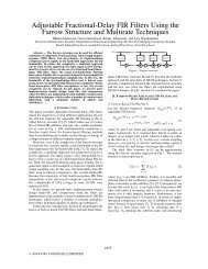
<strong>FRM</strong> <strong>Filter</strong> <strong>Design</strong> <strong>with</strong> <strong>Group</strong> <strong>Delay</strong> <strong>Constraint</strong>Using Second-Order Cone ProgrammingZhiping Lin and Yongzhi LiuSchool of Electrical and Electronic EngineeringNanyang Technological University, Singapore 639798Email: ezplin@ntu.edu.sgAbstract— This paper presents an improved method for thedesign of frequency-response masking (<strong>FRM</strong>) FIR filters <strong>with</strong>reduced passband group delays. Expressions of the group delayand its gradient for an <strong>FRM</strong> filter are derived. To directly andeffectively control the group delay error, a group delay constraintis formulated and incorporated into the overall optimization.The effectiveness and flexibility of the proposed design methodare demonstrated by an example, which shows that significantreduction in group delay error could be achieved at the cost ofslight increase in magnitude error.✲ H1 (z M ) ✲✲+✓✏ – ❄✲ z−Md a ✲ + ✲✒✑Node ‘2’H 3 (z)H4 (z)Node ‘d’✓✏ ❄+ ✲ ✒✑Node ‘f’✻Node ‘e’I. INTRODUCTIONFig. 1.An <strong>FRM</strong> filter structure.The design of linear phase frequency-response masking(<strong>FRM</strong>) filters has attracted much attention in the past twodecades since the <strong>FRM</strong> technique [1] is well known to bevery efficient in the implementation of digital filters <strong>with</strong>sharp transition bands. However, the effective length of alinear phase <strong>FRM</strong> FIR filter is slightly longer than that ofa direct-form FIR filter designed by conventional methods<strong>with</strong> the same approximation accuracy, leading to slightlylarger overall group delay. As a result, linear phase <strong>FRM</strong>FIR filters <strong>with</strong> sharp transition bands have very large groupdelays, which are undesirable in many applications. Thishas motivated some recent interest in designing <strong>FRM</strong> FIRfilters <strong>with</strong> reduced passband group delays [2]–[5]. In thesemethods, the prescribed group delays are indirectly achievedby minimizing the combined magnitude and phase errors, i.e.,the complex magnitude errors. Without any direct constraintin group delay, it is not easy to control the group delayerror, leading to relatively large group delay error, noticeablytowards the bandedges.In this paper, we propose an improved method for thedesign of <strong>FRM</strong> FIR filters <strong>with</strong> reduced passband group delaysby directly imposing a group delay constraint. The proposeddesign method may be considered as a generalization ofthe method in [4], [5] by introducing an additional groupdelay constraint in the overall optimization. The <strong>FRM</strong> filterdesign problem is reformulated by taking into account boththe complex magnitude error and the group delay error. Theproposed approach is similar to but more complicated thanour recent work on the design of FIR filters <strong>with</strong> reducedgroup delay error [6], [7]. One of the key steps of thedesign method proposed in this paper is the derivation ofthe group delay of an <strong>FRM</strong> filter and its gradient <strong>with</strong>respect to the subfilter coefficients. A group delay constraintis then incorporated into the overall optimization. Following[5], another key step is that the optimization is formulatedas a second-order cone programming (SOCP) problem insteadof a semidefinite programming (SDP) one [4], [6] in order toreduce the design time. The effectiveness and flexibility of theproposed design method will be illustrated by an example, andcompared favorably <strong>with</strong> some of the existing design methods.II. GROUP DELAY AND GRADIENTS FOR <strong>FRM</strong> FILTERSDue to space limitation, in this paper we only discuss thedesign of a single stage <strong>FRM</strong> filter <strong>with</strong> a nonlinear phaseprototype filter, a delay line and two linear phase maskingfilters, as illustrated in Fig. 1. The general case of multistage<strong>FRM</strong> filter <strong>with</strong> nonlinear phase masking filters will bereported elsewhere. Throughout this paper, we assume that thelengths of the subfilters are odd. Moreover, for simplicity, thefrequency variable ω is omitted unless otherwise specified.A. <strong>Group</strong> <strong>Delay</strong> for <strong>FRM</strong> <strong>Filter</strong>sLet h 1 = [h 1 (0), h 1 (1), ..., h 1 (N 1 − 1)] T andh l = [ h l ( N l−12), 2h l ( N l−12+1), ..., 2h l (N l − 1) ] T(l = 3, 4) denote the vectors of the coefficients associated<strong>with</strong> the prototype filter of length N 1 and the masking filtersof lengths N l (l = 3, 4), respectively, where the maskingfilters are assumed to satisfy the symmetric condition: h l (n) =h l (N l − 1 − n) (n =0, 1,..., N l−12). Let A i e jφi (i =1, 3, 4)be the frequency responses of H 1 (z M ), H 3 (z) and H 4 (z),respectively, where M is a scaling integer [1]. The magnitude1-4244-0921-7/07 $25.00 © 2007 <strong>IEEE</strong>.2954
and phase responses arewhere h 2 = u da+1 − h 1 (u da+1 is an all-zero vector except√A 1 = (h T 1 c 1) 2 +(h T 1 s having 1 at the (d1) 2 , φ 1 = arctan 2(h T 1 s 1 , h T a +1)-th entry), Sign(x) means the sign of1 c 1 ), x, and PA l = ∣ ( )mω1 and P pω1 are symmetric matrices obtained by∣ hTl c l Nm − 1, φl = −ω, l =3, 4,2P mω1 = 1 )(˜P mω1 + ˜P T mω1 , P pω1 = 1 )(˜P pω1 + ˜P T pω1 ,2 2where N m = max{N 3 ,N 4 }, and c 1 , s 1 and c l (l =3, 4) are(5a)trigonometric vectorsc 1 = [ 1 cosMω ... cos(N 1 − 1)Mω ] ˜P mω1 = c 1˜c T 1 + s 1˜s T 1 , ˜P pω1 = ˜s 1 c T 1 − ˜c 1 s T 1 . (5b)T, (1a)s 1 = [ 0 − sin Mω ... − sin(N 1 − 1)Mω ] The analytic expression of the group delay of an <strong>FRM</strong> filterT, (1b)c l = [ 1 cosω cos 2ω ... cos N l−12ω ] given in (2)-(5) will facilitate the derivation of gradient of theT group delay <strong>with</strong> respect to the subfilter coefficients., l =3, 4,(1c)B. Gradients for <strong>FRM</strong> <strong>Filter</strong>sand(arctany)For an <strong>FRM</strong> filter <strong>with</strong> reduced group delay, both thearctan 2(y, x) ={xfor x ≥ 0,arctan ( yfrequency response and the group delay are nonlinear <strong>with</strong>x)± π otherwise.respect to the subfilter coefficients.The frequency responses at nodes ‘2’, ‘d’, ‘e’ and ‘f’ in Gradient of the Frequency ResponseFig. 1 can be obtained asThe frequency response of an <strong>FRM</strong> filter isA 2 e jφ2 = e −jMdaω − A 1 e jφ1 , A d e jφ d= A 1 A 3 e j(φ1+φ3) ,H f (ω) =H 1 (Mω)H 3 (ω)+ ( e −jMdaω − H 1 (Mω) ) H 4 (ω)A e e jφe = A 2 A 4 e j(φ2+φ4) , A f e jφ f= A d e jφ d+ A e e jφe ,= e −jdmω h T 1 e 1 (h T 3 c 3 − h T 4 c 4 )where d a is the group delay of the prototype filter. To+ e −j(Mda+dm)ω h T 4 c 4 , (6)effectively reduce the group delay of the <strong>FRM</strong> filter, d a shouldbe less than N1−12. Let N f = A d sin φ d + A e sin φ e andwhere e 1 = [ 1 e −jMω e −j2Mω ... e ] −j(N1−1)Mω TD f = A d cos φ d + A e cos φ e . The phase response of the <strong>FRM</strong>and d m = Nm−12. When the design variables are put togetherfilter is φ f = arctan 2(N f , D f ). Using the derivative identityddωarctan 2(y, x) =ddω arctan(y/x) = 1 d(y/x)1+(y/x) 2 dω,the as a design vector x =[h 1 h 3 h 4 ] of dimension N T whereN T = N 1 + N3+12+ N4+12, the gradient of the frequencygroup delay of the <strong>FRM</strong> filter is given by( ) response <strong>with</strong> respect to x is given by1 dNfτ f (ω) =−Df 2 + N f2 dω D dD f⎡f −N f . (2)dH f⎤(ω) ⎡⎤dωdh⎢1e −jdmω (h T 3 c 3 − h T 4 c 4 )e 1dHdN fdω , dD fdAidωcan be subsequently expressed as functions ofdω ,g m (ω) = ⎣f (ω) ⎥dh 3⎦ = ⎣ e −jdmω h T 1 e 1 c 3dH f (ω) e ( ⎦) .−jdmω e −jMdaω − h T dφ i1 e 1 c4dω(i =1, 3, 4)dh 4dN fdω= dA ddω sin φ dφ dd + A d cos φ ddω + dA (7)edω sin φ edD fdω+ A e cos φ edφ edω ,= dA ddω cos φ d − A d sin φ ddφ ddω + dA edω cos φ edφ e− A e sin φ edω ,dA ddω = dA 1dω A dA 33 + A 1dω ,dA edω = dA 2dω A dA 44 + A 2dω ,(3a)(3b)dφ ddω = dφ 1dω + dφ 3dω , (3c)dφ edω = dφ 2dω + dφ 4dω . (3d)Denote ˜s 1 = ds1dω and ˜c i = dcidω(i =1, 3, 4). It can be shownthatdA 1dω = 1 h T 1 P mω1 h 1 ,A 1dA 2dω = 1 h T 2 P mω1 h 2 ,A 2dA ldω = Sign ( h T )l c l hTl ˜c l ,dφ 1dω = 1 A 2 h T 1 P pω1 h 1 , (4a)1dφ 2dω = 1 A 2 h T 2 P pω1 h 2 , (4b)2dφ ldω = −N m − 1, l =3, 4,2(4c)2955Gradient of the <strong>Group</strong> <strong>Delay</strong>Using the group delay expressions given in (2)-(5), thegradient of the group delay <strong>with</strong> respect to x is defined asg τ (ω) =[ (dτf (ω)dh 1) T (dτf (ω)dh 3) T (dτf (ω)dh 4) T] T, (8)whose components, dτ f (ω)dh i(dτ f (ω) 2 dD f=dh i (Df 2 + N f 2 D f )2·( dNfdω D dD ff −N fdω+ dN fdωdD fdh idD fdh i(i =1, 3, 4) aregivenby)dN f+ N fdh i dh i)1−[ d 2 N fdωdh iD fDf 2 + N f2− d2 D f− dD ]f dN f, i =1, 3, 4, (9)dωdh i dω dh id 2 N fdωdh iand d2 D fwhere dN fdh i,dωdh i(i = 1, 3, 4) can beexpressed as functions of dAi dφdh i, i ddh i,2 A idωdh iand d2 φ idωdh i(i =1, 3, 4). Due to space limitation, only the expressions fori =3, 4 are given as following. The expressions for i =1are
similar but more lengthy and omitted here. They are availableat http://www.ntu.edu.sg/home/ezplin/ISCAS07.htm.dN fdh id 2 N f=dωdh idA i= A l sin φ q ,dh( idAldωdD fdh i= A ldA idh icos φ q ,dA i d 2 )A i+ A l sin φ qdh i dωdh idA i+ A l cos φ q ( dφ ldh i dω + dφ idω ),d 2 (D f dAl dA i d 2 )A i= + A l cos φ qdωdh i dω dh i dωdh idA idh i, dφidh i,(10a)(10b)dA i− A l sin φ q ( dφ ldh i dω + dφ idω ),(10c)for (i, l, q) =(3, 1,d) or (i, l, q) =(4, 2,e).d 2 A idωdh iand d2 φ idωdh idA 1dh 1= 1 A 1P mh1 h 1 ,dφ 1= 1 dh 1 A 2 P ph1 h 1 ,1dA ldh l= Sign(h T l c l )c l ,(i =1, 3, 4) are given byd 2 A 1= −1 dA 1 dA 1dωdh 1 A 1 dh 1 dω + 2 P mω1 h 1 ,A 1(11a)d 2 φ 1= −2 dA 1 dφ 1dωdh 1 A 1 dh 1 dω + 2 A 2 P pω1 h 1 ,1(11b)d 2 A l= Sign(h T l c l )˜c l , l =3, 4,dωdh l(11c)where P mh1 = c 1 c T 1 + s 1 s T 1 and P ph1 = s 1 c T 1 − c 1 s T 1 .III. OVERALL OPTIMIZATION FOR <strong>FRM</strong> FILTERSThe design of an <strong>FRM</strong> filter involves two steps. First, asuboptimal <strong>FRM</strong> filter is designed <strong>with</strong> a group of subfilters[1]. Second, overall optimization is carried out to optimize theperformance of the <strong>FRM</strong> filter [4], [5], [8].Let H des (ω), τ des (ω) be the desired frequency responseand passband group delay, and H f (ω, x) and τ f (ω, x) be thedesigned frequency response and passband group delay thatdepend on the design vector x.Problem FormulationDenote the complex magnitude error, η m (ω, x) =|H f (ω, x) − H des (ω)| for ω ∈ Ω m and the group delay error,η g (ω, x) =|τ f (ω, x) − τ des (ω)| for ω ∈ Ω g , where Ω m andΩ g are frequency bands of interest for the magnitude responseand the group delay, respectively. The design of an <strong>FRM</strong> filter<strong>with</strong> reduced group delay error can be formulated as{ {}}minimize maximize max η m (ω, x), max βη g (ω, x) ,xω∈Ω m ω∈Ω g(12)where β is a positive constant balancing the complex magnitudeand group delay errors. Note that β =0reduces to theconventional problem of magnitude optimal <strong>FRM</strong> filter design[5].Estimation Errors for <strong>FRM</strong> <strong>Filter</strong>sSuppose we have a reasonable initial filter x 0 to startoptimization, and we are in the k-th iteration. For a nonlinearand smooth H f (ω, x) at the vicinity of x k , i.e., at x k + v k ,2956where v k is a small vector, the complex magnitude errorbecomes [4], [5]η m (ω, x k + v k )≈ ∣ gTm,k (ω)v k + H f (ω, x k ) − H des (ω) ∣ = ∣ ( gmr,k(ω)v T k + e mr,k (ω) ) + j ( gmi,k(ω)v T k + e mi,k (ω) )∣ ∣(13)where g m,k (ω) =g mr,k + jg mi,k is the gradient of H f (ω, x)<strong>with</strong> respect to x in (7) and evaluated at x k , and e mr,k (ω) =H rf (ω, x k ) − H rd (ω), e mi,k (ω) =H if (ω, x k ) − H id (ω) <strong>with</strong>H rf (ω, x k ), H rd (ω) and H if (ω, x k ), H id (ω) being the realand imaginary parts of H f (ω, x k ) and H des (ω), respectively.Similarly, the group delay error at the k-th iteration can beobtained asη g (ω, x k + v k ) ≈ ∣ ∣g τ,k(ω)v T k + τ f (ω, x k ) − τ des (ω) ∣ = ∣ ∣g τ,k(ω)v T k + e τ,k (ω) ∣ , (14)where g τ,k (ω) is the gradient of the group delay <strong>with</strong> respectto x in (8) and evaluated at x k and e τ,k (ω) =τ f (ω, x k ) −τ des (ω).SOCP FormulationUsing (13) and (14), it follows that an approximated solutionof (12) at the k-th iteration can be obtained by solving thefollowing problemminimize η (15a)subject to :‖G m,k (ω)v k + e m,k (ω)‖ ≤η for ω ∈ Ω m , (15b)β ∥ ( gτ,k(ω)v T k + e τ,k (ω) )∥ ∥ ≤ η for ω ∈ Ωg , (15c)‖v k ‖≤b v ,(15d)where ‖x‖ represents norm of x, b v is a prescribed boundfor v k , e m,k (ω) =[e mr,k (ω) e mi,k (ω)] T and G m,k (ω) =[g mr,k g mi,k ] T . Noted that (15c) is the group delay constraint.Define y k = [η v T k ]T and u 1 = [1 0 ... 0] T . Theconstrained optimization problem defined by (15) can then beformulated as an SOCP problem by digitizing the frequencyvariable ω over a dense set of frequencies in the bands ofinterest. With m K discrete frequency grids {ω 1 , ...,ω mK }⊂Ω m and g K discrete frequency grids {ω 1 , ...,ω gK }⊂Ω g ,the k-th iteration problem in (15) becomesminimize u T 1 y k (16a)subject to :[1 0T0 G m,k (ω l )[ 1 0T0 βg T τ,k (ω i)[0 0T0 I]][ ]0y k +e m,k (ω l )[y k +] [ ]bvy k + ∈C0 p ,0βe τ,k (ω i )∈C l , l =1,...,m K ,(16b)]∈C i , i =1,...,g K ,(16c)(16d)where I is an identity matrix of size N T , and C l , C i and C pare the second-order cones of dimensions 3, 2 and N T +1,
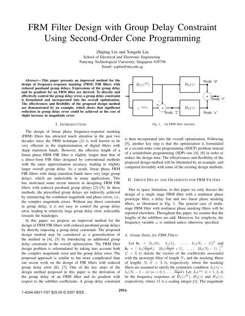
MAGNITUDE (dB)GROUP DELAY0.10.080.060.040.020−0.02−0.04−0.06−0.08−0.10 0.05 0.1 0.15 0.2 0.25 0.3(a) f = ω/(2π)1891881871861851841831821811801881861841821800.29 0.292 0.294 0.296 0.298 0.31790 0.05 0.1 0.15 0.2 0.25 0.3(b) f = ω/(2π)Fig. 2. (a) Passband ripple and (b) passband group delay of the <strong>FRM</strong> filters.The proposed <strong>FRM</strong> filter (β =3× 10 −3 ) is indicated in solid lines whilethe magnitude optimal <strong>FRM</strong> filter is in broken lines.respectively. This problem can be solved efficiently by anySOCP solvers, such as SeDuMi [9] used in the simulations.Having solved the problem in (16) for a minimizer yk ∗ =[ηk ∗ vk ∗T ]T , vector vk ∗ is used to update x k as x k+1 =x k + vk ∗ . The iteration continues until variation of η becomesinsignificantly small.IV. DESIGN EXAMPLEAn <strong>FRM</strong> filter <strong>with</strong> cutoff frequencies ω p =0.6π, ω s =0.61π [1] and desired passband group delay τ des (ω) = 182 isconsidered here. To compare the performance of the designedfilters, some important parameters, such as passband ripple, δ p ,stopband ripple, δ s , both in decibels, and relative ∣ deviation in∣∣ τpassband group delay, defined as D rd = maxf (ω)−τ des (ω) ∣ω∈Ωτ des (ω)∣,gare adopted.Given M =9, a suboptimal <strong>FRM</strong> filter <strong>with</strong> passband groupdelay around 182 and D rd =0.0332 is designed <strong>using</strong> theclassical <strong>FRM</strong> design method [1] <strong>with</strong> N 1 =45, N 3 =41,N 4 =33, d a =18and d m =20. Using this suboptimal filteras an initial design, a magnitude optimal <strong>FRM</strong> filter is obtained<strong>with</strong> D rd =0.0313 <strong>using</strong> the method in [5] or equivalentlythe proposed method <strong>with</strong> β =0. For the overall optimization,900 frequency grids are selected and relatively dense gridpoints are placed in the regions near the bandedges. Using thismagnitude optimal <strong>FRM</strong> filter as an initial design, two optimal<strong>FRM</strong> filters are designed <strong>using</strong> the proposed method <strong>with</strong>β =2×10 −3 and 3×10 −3 , respectively, and b v =1×10 −4 N T(N T =83).As it can be seen from Table I, compared <strong>with</strong> the magnitudeoptimal <strong>FRM</strong> filter, for β =2×10 −3 , the relative deviation inpassband group delay of the proposed <strong>FRM</strong> filter is reducedby 0.006, which corresponds to 18% reduction. However, thepassband and stopband ripples are about 0.001 dB and 0.07dB larger. For β =3× 10 −3 , D rd is reduced by 0.014, whichcorresponds to 43% reduction. However, the passband andstopband ripples increase by 0.04 dB and 0.4 dB, respectively.The performance of the proposed <strong>FRM</strong> filter for β =3×10 −3is also compared <strong>with</strong> that of the magnitude optimal <strong>FRM</strong> filterin Fig. 2, which shows that significant reduction in group delayerror is achieved at the cost of slight increase in magnitudeerror.The above example has clearly demonstrated the flexibilityand effectiveness of the proposed design method in controllingthe group delay error by adjusting β, which balances thecomplex magnitude and the group delay errors.TABLE IDESIGN RESULTS OF THE <strong>FRM</strong> FILTERS.<strong>Filter</strong> β D rd δ p (dB) δ s (dB)Suboptimal filter [1] (NA) 0.0332 0.0845 -40.2190Magnitude optimal filter [5] 0 0.0313 0.0804 -40.6742Proposed filter 2 × 10 −3 0.0255 0.0811 -40.6049Proposed filter 3 × 10 −3 0.0176 0.0839 -40.2662REFERENCES[1] Y. C. Lim, “Frequency-response masking approach for the synthesis ofsharp linear phase digital filters,” <strong>IEEE</strong> Trans. Circuits Syst., vol. CAS-33,pp. 357–364, Apr. 1986.[2] C.-K. Chen and J.-H. Lee, “<strong>Design</strong> of sharp-cutoff FIR digital filters <strong>with</strong>prescribed constant group delay,” <strong>IEEE</strong> Trans. Circuits Syst. II, vol. 43,pp. 1–12, Jan. 1996.[3] L. Svensson and H. Johansson, “Frequency-response masking FIR filters<strong>with</strong> short delay,” in Proc. <strong>IEEE</strong> International Symposium on Circuitsand Systems, vol. III, Phoenix, AZ, May 2002, pp. 233–236.[4] W.-S. Lu and T. Hinamoto, “Optimal design of frequency-responsemaskingfilters <strong>using</strong> semidefinite programming,” <strong>IEEE</strong> Trans. CircuitsSyst. I, vol. 50, pp. 557–568, Apr. 2003.[5] ——, “Optimal design of frequency-response-masking filters <strong>using</strong>second-order cone programming,” in Proc. <strong>IEEE</strong> International Symposiumon Circuits and Systems, vol. III, Bankok, Thailand, May 2003, pp.878–881.[6] Z. Lin and Y. Liu, “FIR filter design <strong>with</strong> group delay constraint <strong>using</strong>semidefinite programming,” in Proc. <strong>IEEE</strong> International Symposium onCircuits and Systems, Island of Kos, Greece, May 2006, pp. 2505–2508.[7] ——, “<strong>Design</strong> of complex FIR filters <strong>with</strong> reduced group delay error<strong>using</strong> semidefinite programming,” <strong>IEEE</strong> Signal Processing Lett., vol. 13,pp. 529–532, Sept. 2006.[8] T. Saramäki, J. Yli-Kaakinen, and H. Johansson, “Optimization offrequency-response masking based FIR filters,” Journal of Circuits,Systems, and Computers, vol. 12, pp. 563–589, May 2003.[9] J. F. Sturm, “Using SeDuMi 1.02, a MATLAB toolbox for optimizationover symmetric cones,” Optimization Methods & Software, vol. 11-12,pp. 625–653, 1999.2957