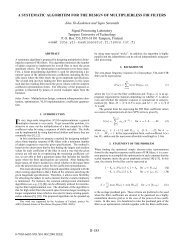
Adjustable Fractional Delay FIR Filters Design Using Multirate and ...
Adjustable Fractional Delay FIR Filters Design Using Multirate and ...
Adjustable Fractional Delay FIR Filters Design Using Multirate and ...

Create successful ePaper yourself
Turn your PDF publications into a flip-book with our unique Google optimized e-Paper software.
1<br />
<strong>Adjustable</strong> <strong>Fractional</strong> <strong>Delay</strong> <strong>FIR</strong> <strong>Filters</strong> <strong>Design</strong><br />
<strong>Using</strong> <strong>Multirate</strong> <strong>and</strong> Frequency Optimization<br />
Techniques<br />
G. Ramirez-Conejo, J. Diaz-Carmona, Member, IEEE, J. Delgado-Frias, Senior, IEEE,<br />
G. Jovanovic-Dolecek, Fellow, IEEE <strong>and</strong> J. Prado-Olivarez<br />
<br />
Abstract— One of the most efficient implementation for<br />
adjustable fractional delay <strong>FIR</strong> filter is the Farrow structure,<br />
allowing on line fractional delay value update with a fixed<br />
branch filters set. A wideb<strong>and</strong> fractional delay <strong>FIR</strong> filter<br />
requires high number of branch filters <strong>and</strong> high branch filters<br />
length, which results in a complex arithmetic implementation.<br />
This paper describes a multirate approach in order to reduce<br />
modified Farrow structure complexity for wideb<strong>and</strong> fractional<br />
delay <strong>FIR</strong> filters. The structure coefficients are computed<br />
through a global minimax frequency optimization process with a<br />
proposed initial solution. According to the obtained results the<br />
use of this initial proposed solution allows fractional delay filters<br />
design meeting severe specifications errors with on line value<br />
update <strong>and</strong> a reduction of multipliers up to 48% compared with<br />
design methods results recently reported.<br />
Index Terms—Digital filters, <strong>FIR</strong> filters, <strong>Fractional</strong> sample<br />
delay, <strong>Multirate</strong>.<br />
F<br />
I. INTRODUCTION<br />
RACTIONAL delay (FD) filters are a very important class<br />
of digital filters. FD filter frequency response is<br />
characterized of having a unit magnitude response <strong>and</strong> a<br />
specified fixed fractional delay response. Hence FD filter<br />
coefficients are obtained meeting both specifications through<br />
a widely type of reported design methods.<br />
In many digital signal processing applications a delay value<br />
equal to a fraction of the sampling period is required. In most<br />
of them on line update of the adjustable fractional value is<br />
needed. Such applications include sample rate conversion in<br />
software-defined radio applications [1], echo cancellation,<br />
phased array antenna systems, <strong>and</strong> modeling of musical<br />
instruments [2].<br />
There are several FD design methods [2], among them the<br />
use of a polynomial approach allows online desired fractional<br />
delay value update using a Farrow structure [3], or a modified<br />
This work was supported by the Mexican National Counsil of Science <strong>and</strong><br />
Technology (CONACyT) under Scholarship Grant number 214724.<br />
G. Ramirez-Conejo, J. Diaz-Carmona <strong>and</strong> J. Prado-Olivarez are with<br />
Department of Electronics Engineering, Technological Institute of Celaya,<br />
Celaya, GTO, MEXICO (e-mail: jdiaz@itc.mx ).<br />
J. Delgado-Frias is with the School of Electrical Engineering, Washington<br />
State Univeristy, Pullman, WA, USA (e-mail: jdelgado@eecs.wsu.edu).<br />
G. Jovanovic-Dolecek is with the Electronics Department, National<br />
Institute of Physics Optics <strong>and</strong> Electronics, Puebla, PUE, MEXICO (e-mail:<br />
gordana@inaoep.mx ).<br />
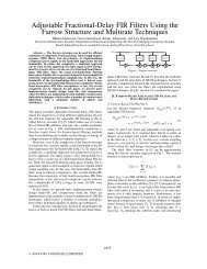
Farrow structure [4]. Both structures are composed of L+1<br />
parallel <strong>FIR</strong> filters C l (z), each one with length N, where L is<br />
the chosen polynomial order, as it is shown in Fig. 1. In a<br />
modified Farrow structure = 2-1, where is the required<br />
fractional delay value, 0
e<br />
l<br />
N<br />
/ 2<br />
<br />
<br />
1<br />
l<br />
N<br />
<br />
, (2)<br />
l<br />
l<br />
n0 2 <br />
2 l!<br />
<br />
C 1<br />
n l,<br />
n,<br />
<br />
where 0 l L <strong>and</strong>:<br />
2<br />
LMS optimization. In the same way the combination of this<br />
multirate structure <strong>and</strong> a frequency optimization technique<br />
were used in subsequent proposals [19]-[20]. In [19] a two<br />
stage FDF jointly optimized technique is applied. In [20] a<br />
complexity reduction is achieved by using an approximately<br />
linear-phase IIR filter instead of a linear-phase <strong>FIR</strong> filter in<br />
the interpolation process.<br />
This paper describes the use of the multirate structure in a<br />
frequency design approach in order to reduce modified<br />
Farrow structure complexity for wideb<strong>and</strong> FD <strong>FIR</strong> filters. A<br />
global minimax frequency optimization is used for structure<br />
coefficients computing, where a coefficients set is proposed as<br />
initial solution. This initial coefficient set is obtained as an<br />
individual solution for the branch filters approximations in a<br />
least mean squares sense. According to the obtained results<br />
the use of the proposed frequency optimization approach<br />
allows a fractional delay structure implementation meeting<br />
small passb<strong>and</strong> magnitude <strong>and</strong> phase delay errors with on line<br />
fractional delay value update requiring small number of<br />
arithmetic operations.<br />
In next section the individual <strong>and</strong> global frequency error<br />
functions, used in the optimization procedure, are defined for<br />
the modified Farrow structure. The multirate structure is<br />
briefly described in third section. In section four the proposed<br />
design method is presented, which is illustrated through two<br />
design examples in section fifth. Finally conclusions are<br />
presented in last section.<br />
II. FREQUENCY ERROR FUNCTIONS<br />
The frequency design method in [7], is based on two facts:<br />
a) the <strong>FIR</strong> branch filters C l (z) in the modified Farrow structure<br />
are linear phase, b) it is possible to approximate the input<br />
signal through Taylor series in a modified Farrow structure.<br />
The l order differential approximation to the continuous-time<br />
interpolated input signal is done through the branch filter<br />
C l (z), with a frequency response given as:<br />
C<br />
l<br />
<br />
e<br />
j<br />
Fig 1. Farrow structure.<br />
<br />
e<br />
N 1<br />
j<br />
2<br />
<br />
j<br />
l<br />
2 l!<br />
l<br />
<br />
. (1)<br />
The individual error function for each branch filter<br />
approximation is given as:<br />
<br />
2 cosn<br />
1/<br />
2<br />
,<br />
l even,<br />
l,<br />
n,<br />
<br />
(3)<br />
<br />
<br />
2 sinn<br />
1/<br />
2<br />
,<br />
l odd.<br />
The global structure errors are defined as:<br />
<br />
<br />
<br />
Complex error:<br />
<br />
H <br />
<br />
, 0 0 1<br />
e . (4)<br />
c<br />
H id<br />
Magnitude error:<br />
m<br />
<br />
H <br />
1,<br />
0 0 1<br />
e . (5)<br />
Phase delay error:<br />
<br />
<br />
<br />
e<br />
p<br />
<br />
<br />
( D ), 0 <br />
p<br />
0 1, (6)<br />
<br />
where H() <strong>and</strong> () are the frequency <strong>and</strong> phase responses,<br />
respectively, of the designed FD filter. H id () is the frequency<br />
response of the ideal FD filter, p is the passb<strong>and</strong> frequency,<br />
<strong>and</strong> D is the transport delay.<br />
III. MULTIRATE STRUCTURE<br />
The multirate structure in [15], is proposed for designing<br />
FD filters in time domain. The input signal b<strong>and</strong>width is<br />
reduced by increasing the sampling frequency. In this way<br />
Lagrange interpolation is used in filter coefficients computing<br />
for a FD filter with a wide b<strong>and</strong>width.<br />
This multirate structure, shown in Fig. 2, is composed of<br />
three stages. The first one is an upsampler <strong>and</strong> a half-b<strong>and</strong><br />
image suppressor filter H HB (z) for incrementing twice the<br />
input sampling frequency. Second stage is the FD filter<br />
H FD (z), which is designed in time domain through Lagrange<br />
interpolation [4]. Since the signal processing frequency of<br />
filter H FD (z) is twice the input sampling frequency, such filter<br />
can be designed to meet only half of the required b<strong>and</strong>width.<br />
Last stage deals with a downsampler for decreasing the<br />
sampling frequency to its original value.<br />
Such multirate structure can be implemented as the singlesampling-frequency<br />
structure shown in Fig. 3, where filters<br />
H 0 (z) <strong>and</strong> H 1 (z) are the first <strong>and</strong> second polyphase components<br />
of the half-b<strong>and</strong> filter H(z), respectively. In the same H FD1 (z)<br />
<strong>and</strong> H FD0 (z) are the polyphase components of FD filter H FD (z).<br />
The design of the FD filter as a modified Farrow structure<br />
in the multirate structure <strong>and</strong> using some structure reductions<br />
results in the final FD structure shown in Fig. 4 [17],[18],with<br />
= 4-1, where is the required fractional delay value, <strong>and</strong><br />
the filters C l,1 (z) <strong>and</strong> C l,0 (z) are the first <strong>and</strong> second polyphase<br />
components of branch filter C l (z), respectively.<br />
p<br />
p
3<br />
X(z)<br />
2<br />
2 H(z) H FD<br />
(z) 2<br />
Fig 2. <strong>Multirate</strong> structure.<br />
Y(z)<br />
X(z)<br />
H 0<br />
(z)<br />
<br />
H 1<br />
(z)<br />
C L,1<br />
(z) C L-1,1<br />
(z) C 1,1<br />
(z) C 0,1<br />
(z)<br />
C L,0<br />
(z) C L-1,0<br />
(z) C 1,0<br />
(z) C 0,0<br />
(z)<br />
Y(z)<br />
2<br />
Fig 4. Resulting FD structure.<br />
X(z) H 0 () z H FD1 () z Yz ()<br />
IV. PROPOSED DESIGN METHOD<br />
The coefficients computing of the resulting FD structure,<br />
shown in Fig. 4, is done through frequency optimization for<br />
the global structure magnitude approximation to the ideal<br />
frequency response in a minimax sense. The objective<br />
function is defined as:<br />
<br />
<br />
<br />
max max <br />
<br />
<br />
, (7)<br />
0 1,<br />
0<br />
<br />
p<br />
m e m<br />
where e m () is the global magnitude error. This objective<br />
function is minimized until the magnitude error specification<br />
m is met. Since approximation must meet both magnitude <strong>and</strong><br />
phase errors, then global phase delay error is constrained to<br />
meet next phase delay restriction:<br />
<br />
<br />
<br />
max max , (8)<br />
0<br />
10<br />
<br />
p <br />
p e p p<br />
where e p () is the global phase error <strong>and</strong> p is the phase delay<br />
error specification.<br />
As is well known the initial solution is a very important<br />
factor for a minimax optimization process, [11], the proposed<br />
initial coefficients set is the least mean squares solution of the<br />
individual branch filters approximations to differentiators,<br />
hence the approximation error of the l th branch filter is given<br />
as:<br />
E<br />
l<br />
H 1 () z<br />
p<br />
2<br />
0<br />
e<br />
<br />
d<br />
l<br />
H FD0 () z<br />
2<br />
Fig 3. Resulting structure for the FD filter.<br />
2<br />
, (9)<br />
where the upper frequency limit is half the desired FD<br />
b<strong>and</strong>width, this is due to the increment of the sampling<br />
frequency in upsampler stage.<br />
The half-b<strong>and</strong> filter H HB (z) can be designed as a Doph-<br />
Chebyshev window or as an equirriple filter. The final halfb<strong>and</strong><br />
filter coefficients are obtained from the optimization<br />
process.<br />
V. DESIGN EXAMPLES<br />
Two design examples are described where the proposed<br />
FD filter design results are compared with already reported<br />
ones. The minimax optimization process was performed<br />
through the function fminimax available in the MATLAB<br />
Optimization Toolbox.<br />
Example 1: In this example the specifications are<br />
p m = 0.01 <strong>and</strong> p =0.001, same design example as<br />
[12]. The given criteria is met with N = 7 <strong>and</strong> L = 4 <strong>and</strong> a halfb<strong>and</strong><br />
filter length of 55. The overall structure requires M = 32<br />
multipliers, A = 47 adders, resulting in a m = 0.0094448 <strong>and</strong><br />
p = 0.00096649. The obtained magnitude <strong>and</strong> phase delay<br />
responses for = 0 to 0.5 with 0.1 delay increment are<br />
depicted in Fig. 5. In Table I are shown the obtained results<br />
with the proposed method <strong>and</strong> thus reported by other design<br />
methods. Our design requires less multipliers <strong>and</strong> adders than<br />
[4], [11], the same number of multipliers <strong>and</strong> nine less adders<br />
Method<br />
TABLE I.<br />
EXAMPLE 1 RESULTS COMPARISON<br />
Arithmetic complexity<br />
N L M A m p<br />
Vesma 97 [4] 26 4 69 91 0.006571 0.0006571<br />
Johansson 03<br />
[11]<br />
28 5 57 72 0.005608 0.0005608<br />
Yli 06 [12] 28 4 32 56 0.009069 0.0009069<br />
Yli 06 [13] 28 4 31 50 0.009742 0.0009742<br />
Yli 07 [14] 28 4 30 - 0.009501 0.0009501<br />
Proposed 7 4 32 47 0.0094448 0.0009664<br />
Magnitude Response<br />
Phase <strong>Delay</strong> Response<br />
1.01<br />
1<br />
- Not reported<br />
0.99<br />
0 0.1 0.2 0.3 0.4 0.5 0.6 0.7 0.8 0.9 1<br />
Normalized Angular Frequency /<br />
a)<br />
14.5<br />
14.4<br />
14.3<br />
14.2<br />
14.1<br />
14<br />
0 0.1 0.2 0.3 0.4 0.5 0.6 0.7 0.8 0.9 1<br />
Normalized Angular Frequency /<br />
b)<br />
Fig 5. FD Filter frequency responses for =0.0 to 0.5 in Example 1.<br />
a) Magnitude response, b) Phase delay response.
4<br />
than [12], one more multiplier <strong>and</strong> three less adders than [13],<br />
<strong>and</strong> two more multipliers than [14].<br />
Example 2: This example shows that the purpose<br />
optimization method can be extended for minimax<br />
approximation of a global complex error. For this proupose<br />
the filter design example described in [11] is used, which<br />
specifications are p <strong>and</strong> maximum global complex<br />
error of c = 0.0042. Such specifications are met with N = 7<br />
<strong>and</strong> L = 4 <strong>and</strong> a half-b<strong>and</strong> filter length of 69. The overall<br />
structure requires M = 35 multipliers with a resulting<br />
maximum complex error c = 0.0036195. The fractional delay<br />
range is between 17.5 <strong>and</strong> 18.5. In Table II the obtained<br />
results are compared with the reported in existing methods.<br />
The proposed method requires less multipliers than [11], [16]<br />
<strong>and</strong> case A of [19]. Reported multipliers of [20] <strong>and</strong> case B of<br />
[19] are less that the obtained with the proposed design<br />
method. It should be pointed out that in [20] an IIR half-b<strong>and</strong><br />
filter is used <strong>and</strong> in case B of [19] <strong>and</strong> [20] a switching<br />
technique between two multirate structures must be<br />
implemented. The complex error magnitude <strong>and</strong> magnitude<br />
response of the proposed design for = -0.5 to 0 with 0.1<br />
delay increment are shown in Fig. 6.<br />
VI. CONCLUSIONS<br />
The use of a frequency design method for wideb<strong>and</strong><br />
fractional delay <strong>FIR</strong> filters using a multirate Farrow structure is<br />
described, where resulting filter coefficients are obtained with<br />
a global structure approximation to the ideal frequency<br />
response of a fractional delay filter through minimax<br />
optimization. The proposed design method is based on starting<br />
the optimization process from an initial structure coefficients<br />
set, which is obtained as a least mean squares solution of<br />
individual branch filters approximations to ideal differentiator<br />
responses. As the presented examples demostrate, the<br />
proposed method can be used in the design of wideb<strong>and</strong><br />
fractional delay <strong>FIR</strong> filters meeting magnitude <strong>and</strong> phase<br />
specifications with online fractional delay value capability, <strong>and</strong><br />
TABLE II.<br />
Method<br />
EXAMPLE 2 RESULTS COMPARISON<br />
Arithmetic complexity<br />
N L M<br />
Johannson 03 [11] 39 6 73<br />
Johannson 03 a [11] 31 5 50<br />
Hermanowicz 04 [16] 11 6 60(54)<br />
Hermanowicz 05 [19] 7 5 36<br />
Hermanowicz 05 b [19] 7 3 26<br />
Johannson 06 [20] - 6 32<br />
Johannson 06 b [20] - 3 22<br />
Proposed 7 4 35<br />
a. Minimax design with subfilters jointly optimized.<br />
b. Switching structures. - Not reported<br />
Magnitude Response<br />
4 10-3 3<br />
2<br />
1<br />
0<br />
0 0.1 0.2 0.3 0.4 0.5 0.6 0.7 0.8 0.9 1<br />
x<br />
Normalized Angular Frequency /<br />
a)<br />
1.005<br />
Complex Error Magnitude<br />
1<br />
0.995<br />
0 0.1 0.2 0.3 0.4 0.5 0.6 0.7 0.8 0.9 1<br />
Normalized Angular Frequency /<br />
b)<br />
Fig 6. Filter frequency responses for =-0.5 to 0 in Example 2. a)<br />
Complex error magnitude, b) Magnitude response.<br />
smaller arithmetic complexity than existing fractional delay<br />
<strong>FIR</strong> design methods.<br />
VII. ACKNOWLEDGMENT<br />
The authors would like to thank to the School of Electrical<br />
Engineering <strong>and</strong> Computer Science at Washington State<br />
University for the facilities in the project development, <strong>and</strong> to<br />
CONACyT for scholarship grant number 214724.<br />
VIII. REFERENCES<br />
[1] T. Hentschel, <strong>and</strong> G. Feetweis, “Sample rate conversion for software<br />
radio,” IEEE Communications Magazine, vol. 38, no. 8, pp. 142-150,<br />
Aug. 2000.<br />
[2] T. I. Laakso, V. Valimaki, M. Karjalainen, <strong>and</strong> U. K. Laine, “Splitting<br />
the unit delay: tools for fractional filter design,” IEEE Signal Processing<br />
Magazine, vol. 13, no. 1, pp. 30-60, 1996.<br />
[3] C. W. Farrow, “A continuously variable digital delay element,” in Proc.<br />
IEEE Int. Symp. Circuits <strong>and</strong> Systems, Espoo, Finl<strong>and</strong>, June 7-9, 1988,<br />
vol. 3, pp. 2641-2645.<br />
[4] J. Vesma <strong>and</strong> T. Saramaki, “Optimization <strong>and</strong> efficient implementation<br />
of <strong>FIR</strong> filters with adjustable fractional delay,” in Proc. IEEE Int. Symp.<br />
Circuits <strong>and</strong> Systems, Hong Kong, June 9-12, 1997, pp. 2256-2259.<br />
[5] C. Cagatay, “An efficient filter structure for lagrange interpolation,”<br />
IEEE Signal Processing Letters, vol. 14, no. 1, pp. 17-19, 2007.<br />
[6] S. Samadi., M. Ahmad <strong>and</strong> M. Swamy, “Characterization of B-spline<br />
digital filters,” IEEE Trans. Circuits <strong>and</strong> Systems-I: Regular papers, vol.<br />
51, no. 4, pp. 808-816, 2004.<br />
[7] J. Vesma, R. Hamila, T. Saramaki <strong>and</strong> M. Renfors, “<strong>Design</strong> of<br />
polynomial-based interpolation filters based on Taylor series,” in Proc.<br />
IX European Signal Processing Conference, September 1998, pp. 283-<br />
286.<br />
[8] A. Tarczynski, G. D. Cain, E. Hermanovicz, <strong>and</strong> M. Rojewski, “WLS<br />
design of variable frequency response <strong>FIR</strong> filters,” in Proc. IEEE Int.<br />
Symp. Circuits <strong>and</strong> Systems, Hong Kong, June 9-12, 1997, pp. 2244-<br />
2247.<br />
[9] T. B. Deng, “Discretization-free design of variable fractional-delay <strong>FIR</strong><br />
filters,” IEEE Trans. Circuits Syst. II Analog Digit, Signal Process., vol.<br />
48, no. 6, pp. 637-644, June 2001.<br />
[10] H. Zhao <strong>and</strong> J. Yu, “A simple <strong>and</strong> efficient design of variable fractional<br />
delay <strong>FIR</strong> filters,” IEEE Trans. On Circuits <strong>and</strong> Systems-II:Express<br />
Brief, vol. 53, no. 2, pp. 157-160, February 2006.<br />
[11] H. Johansson <strong>and</strong> P. Lowenborg, “On the <strong>Design</strong> of <strong>Adjustable</strong><br />
<strong>Fractional</strong> <strong>Delay</strong> <strong>Filters</strong>”, IEEE Trans. Circuits <strong>and</strong> Systems – II, Analog<br />
<strong>and</strong> Digital Signal Processing, vol. 50, no 4, pp. 164-169, 2003.<br />
[12] J. Yli-Kaakinen <strong>and</strong> T. Saramäki, “Multiplication-free polynomial based<br />
<strong>FIR</strong> filters with an adjustable fractional delay,” Circuits, Syst., Signal<br />
Processing, vol. 25, no. 2, pp. 265–294, April 2006.
5<br />
[13] J. Yli-Kaakinen <strong>and</strong> T. Saramäki, “An efficient structure for <strong>FIR</strong> filters<br />
with an adjustable fractional delay,” in Proc. Digital Signal Processing<br />
Applications, Moscow, Russia, March 29–31, 2006, vol. 2, pp. 617–623.<br />
[14] J. Yli-Kaakinen <strong>and</strong> T. Saramäki, “A simplified structure for <strong>FIR</strong> filters<br />
with an adjustable fractional delay,” in Proc. IEEE Int. Symp. Circuits<br />
<strong>and</strong> Systems, New Orleans, USA, May 27-30 , 2007, pp. 3439-3442.<br />
[15] N.P. Murphy, A. Krukowski <strong>and</strong> I. Kale,“Implementation of a wideb<strong>and</strong><br />
integer <strong>and</strong> fractional delay element”, Electronics Letters, vol. 30,<br />
no 20, pp. 1658-1659, 1994.<br />
[16] E. Hermanowicz, “On <strong>Design</strong>ing a Wideb<strong>and</strong> <strong>Fractional</strong> <strong>Delay</strong> Filter<br />
using the Farrow Approach”, in Proc. of XII. European Signal<br />
Processing Conference, Vienna, Austria, September 6-10, 2004, pp.<br />
961-964.<br />
[17] G. Jovanovic-Dolecek, <strong>and</strong> J. Diaz-Carmona, “One structure for<br />
fractional delay filter with small number of multipliers,” Electronics<br />
Letters, vol. 38, no. 19, pp. 1083-1084, September 2002.<br />
[18] J. Diaz-Carmona, G. Jovanovic-Dolecek <strong>and</strong> A. Ramirez-Agundis,<br />
"Frequency-based optimization design for fractional delay <strong>FIR</strong> filters<br />
with software-defined radio applications," International Journal of<br />
Digital Multimedia Broadcasting, Hindawi Publising Corp., pp. 1-6,<br />
2010.<br />
[19] E. Hermanowicz <strong>and</strong> H. Johansson, “On designing minimax adjustable<br />
wideb<strong>and</strong> fractional delay <strong>FIR</strong> filters using two-rate approach,” in Proc.<br />
European Conf. Circuit Theory <strong>Design</strong>, Cork, Irel<strong>and</strong>, August 29–<br />
September 1, 2005, pp. 961-964.<br />
[20] H. Johansson <strong>and</strong> E. Hermanowicz, “<strong>Adjustable</strong> fractional delay filters<br />
utilizing the Farrow structure <strong>and</strong> multirate techniques,” in Proc. Sixth<br />
Int. Workshop Spectral Methods <strong>Multirate</strong> Signal Processing, Florence,<br />
Italy, September. 1–2, 2006.<br />
IX. BIOGRAPHIES<br />
Guillermo Ramírez-Conejo received B. S. <strong>and</strong> M.<br />
S. degrees from the Technological Institute of<br />
Celaya (ITC), Celaya Gto. México, in 2007 <strong>and</strong><br />
2010, respectively, both in Electronic Engineering.<br />
ITC. In first semester of 2009 he was professor at<br />
the Basic Science Department, ITC. In second<br />
semester of 2009 he was a visiting scholar at School<br />
of Electrical Engineering <strong>and</strong> Computer Science,<br />
Washington State University, Pullman, USA, where<br />
he performed last research stage of his M. S. thesis<br />
project. Currently he is a faculty member at the Mechatronics Engineering<br />
Department in the ITC. His research interest includes reconfigurable<br />
computing <strong>and</strong> digital filters.<br />
Javier. Diaz-Carmona received a B. S. degree in<br />
Electronics Engineering in 1990 from the<br />
Technological Institute of Celaya (ITC), Celaya Gto,<br />
Mexico, a M. S. degree in 1997 <strong>and</strong> a Doctor in<br />
Science degree in Electronics in 2003 from the<br />
National Institute of Astrophysics Optics <strong>and</strong><br />
Electronics (INAOE), Puebla, Mexico. Since 1991 he<br />
is faculty member at the Electronics Engineering<br />
Department in the ITC, currently as full time professor<br />
<strong>and</strong> researcher. He is author <strong>and</strong> co-author of more<br />
than 40 papers. His research interests include Digital Signal Processing,<br />
digital filter design techniques <strong>and</strong> Microcontoller, DSP/FPGA embedded<br />
systems applications. He is member of IEEE <strong>and</strong> National Researcher System<br />
(SNI) Mexico.<br />
Binghamton, University of Virginia, <strong>and</strong> Princeton University. His research<br />
interests include high-performance VLSI systems, reconfigurable<br />
architectures, network routers, <strong>and</strong> nanotechnology. He has co-authored over<br />
170 journal <strong>and</strong> conference papers <strong>and</strong> co-edited five books. He has been<br />
granted twenty-seven patents. Dr. Delgado-Frias has chaired several<br />
international conferences, recently he chaired the 53rd IEEE Midwest<br />
Symposium on Circuits <strong>and</strong> Systems 2010. He received the SUNY System<br />
Chancellor’s Award for Excellence in Teaching in 1994. He is a senior<br />
member of the IEEE, <strong>and</strong> a member of the Association for Computer<br />
Machinery (ACM) <strong>and</strong> American Society for Engineering Education (ASEE).<br />
Gordana Jovanovic-Dolecek received a B. S.<br />
degree from the Department of Electrical<br />
Engineering, University of Sarajevo, an M. S.<br />
degree from University of Belgrade, <strong>and</strong> a PhD<br />
degree from the Faculty of Electrical Engineering,<br />
University of Sarajevo, where she was professor<br />
until 1993, <strong>and</strong> 1993-1995 she was with the<br />
Institute Mihailo Pupin, Belgrade. In 1995 she<br />
joined to the National Institute of Astophysics<br />
Optics <strong>and</strong> Electronics (INAOE), Department for<br />
Electronics, Puebla, Mexico, where she currently works as a professor <strong>and</strong><br />
researcher. During 2001-2002, 2006 she was at Department of Electrical &<br />
Computer Engineering, University of California, Santa Barbara, USA, as<br />
visiting researcher. In 2008-2009 she was as visiting researcher at the<br />
Department of Electrical <strong>and</strong> Computer Engineering, San Diego State<br />
University, USA. She is the author of three books, editor of one book, <strong>and</strong><br />
author of more than 200 papers. Her research interests include digital signal<br />
processing <strong>and</strong> digital communications. She is a Fellow member of IEEE, the<br />
member of Mexican Academy of Science, <strong>and</strong> the member of National<br />
Researcher System (SNI) Mexico.<br />
Juan Prado-Olivarez. He received the B. S.<br />
degree in Electronics Engineering in 1993 from<br />
the Technological Instiute of Celaya, Celaya Gto,<br />
Mexico, a M. S. degree from School of Electrical,<br />
Mechanical <strong>and</strong> Electronics Engineering of the<br />
Univeristy of Guanajuato, Salamanca Gto, <strong>and</strong> a<br />
PhD degree in 2006 from the Laboratoire de<br />
Instrumentation et microélectronique de Nancy,<br />
Nancy, France. Since 2007 he is faculty member<br />
at the Electronics Engineering Department in the<br />
ITC, currently as full time professor <strong>and</strong> researcher. His topics of interest are<br />
biomedical sensors, spectroscopy impedance <strong>and</strong> noninvasive measurement of<br />
physiological parameters. He is member of the National Researcher System<br />
(SNI) Mexico.<br />
José G. Delgado-Frias received a B. S. degree from<br />
the National Autonomous University of Mexico,<br />
Mexico City, Mexico, an M.S. degree from the<br />
National Institute for Astrophysics, Optics <strong>and</strong><br />
Electronics (INAOE), Puebla, Mexico, <strong>and</strong> a Ph.D.<br />
degree from Texas A&M University, College<br />
Station, TX, all in electrical engineering. He is<br />
currently professor at the School of Electrical<br />
Engineering <strong>and</strong> Computer Science, Washington<br />
State University, Pullman, where he holds the<br />
Boeing Centennial Chair in Computer Engineering. He has held academic<br />
positions at Oxford University, State University of New York (SUNY) at