Instruction Manual - Beta Industries
Instruction Manual - Beta Industries
Instruction Manual - Beta Industries

You also want an ePaper? Increase the reach of your titles
YUMPU automatically turns print PDFs into web optimized ePapers that Google loves.
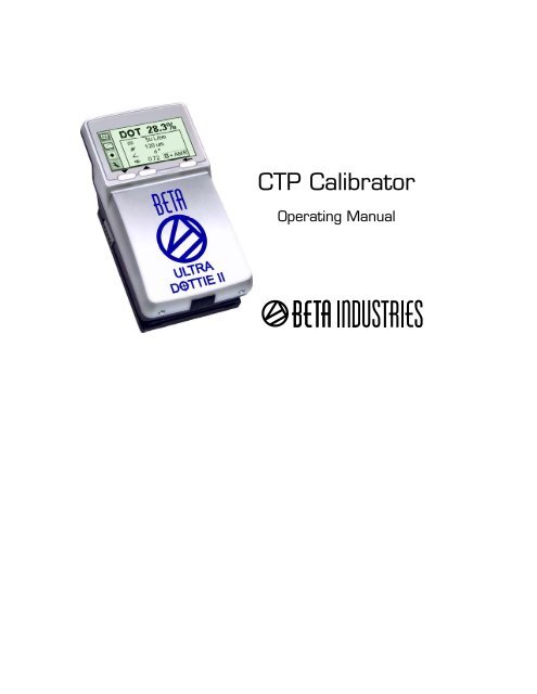
UltraDottie II<br />
CTP Calibrator<br />
Operating <strong>Manual</strong>
ULTRADOTTIE II<br />
Plate Reader<br />
Version 1.03<br />
1/49
1 TABLE OF CONTENTS 3<br />
2 GENERAL 5<br />
2.1 INTRODUCTION 7<br />
2.2 SAFETY 8<br />
2.2.1 Warning 8<br />
2.2.2 General safety tips 8<br />
2.3 PACKAGING AND TRANSPORT 9<br />
2.4 BASIC EQUIPMENT AND ACCESSORIES 9<br />
2.5 ACCESSORIES 10<br />
2.5.1 <strong>Beta</strong>Tab software 10<br />
2.5.2 <strong>Beta</strong>Target(Optional) 10<br />
2/49
3 OPERATION 11<br />
3.1 FUNCTIONAL ELEMENTS 13<br />
3.2 FIRST STEPS FOR USE 14<br />
3.2.1 Power-saving mode 14<br />
3.2.2 Toolbar 15<br />
3.2.3 Identifying the symbols 15<br />
3.3 ADJUSTING DEVICE SETTINGS 20<br />
3.4 INPUTTING A REFERENCE CURVE 21<br />
3.5 MEASURING 23<br />
3.5.1 General 23<br />
3.5.2 Calibration 25<br />
3.5.3 Measuring standard plates 25<br />
3.5.4 Measuring polyester plates 26<br />
3.5.5 Measuring film 26<br />
3.5.6 Measuring paper 27<br />
3.5.7 Measurement values 27<br />
3.6 VISUALLY CHECKING THE DOT 29<br />
3.7 MEASURING A PLATE CHARACTERISTIC CURVE 30<br />
3/49
3.8 UltraDottie IIII MAINTENANCE AND CARE 32<br />
3.8.1 RESET 32<br />
3.8.2 Replacing the batteries 33<br />
4 APPENDIX 35<br />
4.1 TECHNICAL DATA 37<br />
4.2 SERIAL INTERFACE 38<br />
4.3 DECLARATION OF CONFORMITY 39<br />
4/49
2 General 5<br />
2.1 INTRODUCTION 7<br />
2.2 SAFETY 8<br />
2.2.1 Warning 8<br />
2.2.2 General safety tips 8<br />
2.3 PACKAGING AND TRANSPORT 9<br />
2.4 BASIC EQUIPMENT AND ACCESSORIES 9<br />
2.5 ACCESSORIES 10<br />
2.5.1 <strong>Beta</strong>Tab software 10<br />
2.5.2 <strong>Beta</strong>Target(Optional) 10<br />
1<br />
5/49
2 General<br />
2.1 Introduction<br />
Dear <strong>Beta</strong> <strong>Industries</strong> customer:<br />
Congratulations! You have just acquired the portable plate measuring device<br />
UltraDottie II made by <strong>Beta</strong> <strong>Industries</strong>. This device solves one of the most difficult<br />
tasks in the printing industry – quick and accurate quality control of the<br />
Computer-to-Plate (CtP) process. With the help of its built-in video camera the<br />
UltraDottie II geometrically analyzes the dot area of any given test patches with<br />
regular or stochastic screens. Where applicable the dot diameter, screen ruling,<br />
the screen angle and the visual coverage are calculated and displayed. The<br />
quality of the dot form of a screen type occasionally has to be assessed. This<br />
can be done with the UltraDottie II at a resolution of 12,700 ppi (pixels per inch) or<br />
6,350 ppi as a matter of choice. To avoid having to check each individual<br />
measurement during the linearization of a CtP, the UltraDottie II offers the<br />
possibility of measuring an entire curve with up to 100 sample points and then<br />
transferring it to a host PC. <strong>Beta</strong> <strong>Industries</strong> also offers <strong>Beta</strong>Tab software,<br />
6/49
with which the data can be copied into a word processor, a spreadsheet or<br />
another software program.<br />
The power-saving electronics and LED technology allow up to 30,000 measurements<br />
for each set of batteries (2 ordinary commercial AA batteries), which<br />
means that no limits are placed on mobility.<br />
With the icon-based, graphical user interface <strong>Beta</strong> <strong>Industries</strong> is opening up<br />
new paths and offers the user a simple, easy to understand operating concept.<br />
2<br />
7/49
2.2 Safety<br />
2.2.1 Warning<br />
For safety reasons it is absolutely necessary to read through the<br />
user’s guide and all of the instructions it contains.<br />
2.2.2 General safety tips<br />
If the safety recommendations and instructions in this User Guide<br />
are not complied with, this can lead to measurement errors or data<br />
loss or involve physical injury or damage to property.<br />
• UltraDottie II is not intrinsically safe. Therefore the device cannot<br />
be used in an environment where there is a risk of explosion.<br />
• UltraDottie II may not be used in an area with strong<br />
electromagnetic fields.<br />
• Use the UltraDottie II in ambient temperatures between 10°C (50°º F) and<br />
40°C (104°F), and do not expose the UltraDottie II to direct sun light.<br />
• UltraDottie II should never be opened up. The guarantee expires<br />
immediately upon unauthorized opening of the device. Contact<br />
your dealer if repairs prove to be necessary.<br />
8/49
• To avoid incorrect handling, the UltraDottie II should only be used by<br />
trained personnel..<br />
• UltraDottie II should only be used on dry and stable measuring surfaces.<br />
• UltraDottie II should be protected against chemicals, corrosive vapors,<br />
strong mechanical vibrations and impacts.<br />
• Use original <strong>Beta</strong> <strong>Industries</strong> spare parts and accessories only.<br />
• Use the original packaging exclusively when transporting the device.<br />
• The UltraDottie II case can be cleaned with a cloth moistened with soapy water<br />
2of<br />
9/49
2.3 Packaging and transport<br />
Always transport UltraDottie II in the original device case to avoid damage.<br />
Safeguard the measuring foot by pushing back the locking device.<br />
<strong>Beta</strong> <strong>Industries</strong> cannot be liable for damage to the UltraDottie II during<br />
transport that can be traced back to inadequate packaging or an<br />
unlocked measuring foot.<br />
2.4 Basic equipment and accessories<br />
The UltraDottie II and the associated standard accessories are supplied in a<br />
fitted case. Please check the contents of the device case for completeness<br />
on delivery.<br />
The following components must be present:<br />
• UltraDottie II<br />
• User guide<br />
2Contents<br />
10/49
2.5 Accessories<br />
To perform and document quality control, it is often necessary to save<br />
the measured data on a PC.<br />
2.5.1 <strong>Beta</strong>Tab software<br />
The <strong>Beta</strong>Tab software enables you to transfer the measured data and<br />
binary images to your PC or Macintosh and to copy these into a given program<br />
(e.g. word processor, spreadsheet). The screen dot as well as the<br />
associated measurement values will be transferred and can then be<br />
used for statistical analysis. This software is an ideal tool for<br />
documenting measurement results.<br />
11/49
2.5.2 <strong>Beta</strong> Target (Optional)<br />
The <strong>Beta</strong>Target is a long-term stable absolute reference. You can use<br />
the <strong>Beta</strong>Target to test the device for its accuracy, to carry out an<br />
upgrade and if necessary to calibrate it.<br />
<strong>Beta</strong>Target technical data:<br />
Dot: 28.3%<br />
Lines/cm: 50<br />
Dot size: 120µm<br />
The reference plate used by <strong>Beta</strong> <strong>Industries</strong> is an extremely precise<br />
glass substrate that is metal vaporized and, as is used in<br />
semiconductor manufacturing, etched out. It is embedded in gray<br />
plastic. The reference plate has a lifetime of two years. The expiration<br />
date and the serial number are printed on the label.<br />
2<br />
12/49
3 OPERATION 11<br />
3.1 FUNCTIONAL ELEMENTS 13<br />
3.2 FIRST STEPS FOR USE 14<br />
3.2.1 Power-saving mode 14<br />
3.2.2 Toolbar 15<br />
3.2.3 Identifying the symbols 15<br />
3.3 ADJUSTING DEVICE SETTINGS 20<br />
3.4 INPUTTING A REFERENCE CURVE 21<br />
3.5 MEASURING 23<br />
3.5.1 General 23<br />
3.5.2 Calibration 25<br />
3.5.3 Measuring standard plates 25<br />
3.5.4 Measuring polyester plates 26<br />
3.5.5 Measuring film 26<br />
3.5.6 Measuring paper 27<br />
3.5.7 Measurement values 27<br />
3.6 VISUALLY CHECKING THE DOT 29<br />
3.7 MEASURING A PLATE CHARACTERISTIC CURVE 30<br />
13/49
3.8 UltraDottie IIII MAINTENANCE AND CARE 32<br />
3.8.1 RESET 32<br />
3.8.2 Replacing the batteries 33<br />
1<br />
2<br />
3<br />
Table of<br />
14/49
Operation : Functional Elements<br />
on bottom<br />
LCD Display<br />
<br />
button<br />
button<br />
Positioning Aid<br />
Locking button<br />
RS232 Interface<br />
0° Positioning<br />
15/49
3.2 First steps for use<br />
Release the measuring head by sliding the locking device on the left<br />
side forward. After initial opening or after pressing the <br />
button (red button on the bottom side of the measuring head) the<br />
start-up screen appears on the display.<br />
The version number of the firmware and the device serial number are<br />
shown on the bottom left of the screen. If you have technical questions,<br />
please communicate this information to the manufacturer.<br />
The device’s factory settings have been selected to enable you to begin<br />
measuring plates immediately. The UltraDottie II is configured as follows:<br />
• Standard plate<br />
• Lines/inch<br />
• Regular screen (AM)<br />
16/49
• Red LED (a standard plate is typically measured with the red LED)<br />
3.2.1 Power-saving mode<br />
The UltraDottie II changes over automatically to power-saving mode after<br />
approximately 30 seconds. This is announced by displaying the<br />
‘Sleep’ symbol. The display will then fade out. Tapping any<br />
button on the device will reproduce the last display.<br />
3.2.2 Toolbar<br />
The toolbar appears on the left on the display and displays the<br />
functions available using symbols. A cursor (black frame surrounding<br />
the symbol) can be moved through the toolbar using the and<br />
buttons (see section 3.1).<br />
Functions available using symbols. A cursor (black frame surrounding<br />
the symbol) can be moved through the toolbar using the and<br />
17/49
uttons (see section 3.1).<br />
The function designated by the cursor is executed by pressing the<br />
button. In normal operating mode the cursor moves after<br />
approximately 5 seconds to the default position. To re-position the<br />
cursor simply tap the or button.<br />
3.2.3 Meaning of the symbols<br />
3.2.3.1 Change display mode<br />
Next display<br />
Previous display<br />
Change to image display for a visual dot inspection<br />
Increase representation resolution to 12,700 ppi<br />
Reduce representation resolution to 6,350 ppi<br />
18/49
Change to characteristic curve display<br />
Device Settings<br />
3<br />
3.2.3.2 Move the sub-cursor<br />
Shift the sub-cursor from left to right<br />
Shift the sub-cursor from right to left<br />
Shift the sub-cursor downwards / Decrease value<br />
Shift the sub-cursor upwards / Increase value<br />
3.2.3.3 Device Settings<br />
Standard plate<br />
Polyester plate<br />
Paper<br />
Film<br />
Screen ruling in (lines/cm)<br />
19/49
Screen ruling in (lines/inch)<br />
Regular screening (AM)<br />
Stochastic screening (FM).<br />
Illumination for plate measurement R (Red LED), G (Green LED), B (Blue LED)<br />
Color for paper measurement C (Cyan LED), M (Green LED), Y (Blue LED), K (Green LED)<br />
Automatic CMY color recognition during paper measurement<br />
Positive dot %<br />
Negative dot %<br />
20/49
3.2.3.4 Other functions<br />
Transfer current record (binary image or characteristic curve) to the host PC<br />
Device is calculating (during measurement and data transfer)<br />
Device is changing over to power-saving mode<br />
Add reference value<br />
Delete reference value<br />
Restart and delete all previous settings<br />
3.2.3.5 Symbols for measurement results<br />
Screen ruling in lines/cm or lines/inch<br />
Dot diameter in mm (based on a circular dot of the same surface area)<br />
21/49
Screen angle in °<br />
Logarithmic Reflectance Value<br />
3.2.3.6 Status information<br />
Standard plate<br />
Polyester plate<br />
Paper<br />
Film<br />
Batteries need to be exchanged<br />
+ Positive dot %<br />
- Negative dot %<br />
AM Regular screening<br />
FM Stochastic screening<br />
R Red illumination for plate measurement<br />
G Green illumination for plate measurement<br />
22/49
3.3 Adjusting device settings<br />
After unpacking or after pressing the button,<br />
you can use UltraDottie II to begin measuring standard<br />
plates using the factory settings, or change the display of<br />
the device settings by selecting the ‘Next display’ symbol<br />
You will find the toolbar on the left of the display with<br />
functions that allow you to move the sub-cursor. On the<br />
right side of the display you will find one column for each<br />
group of settings.<br />
• Measurement medium (standard plate, polyester plate,<br />
paper or film)<br />
• Dot % display (Positive or Negative)<br />
The currently selected group of settings is highlighted by a black<br />
frame surrounding the symbols. The setting can be altered as follows.<br />
Select the function with the or buttons and<br />
execute this by pressing the button. This enables<br />
you to move the subcursor (double black frame surrounding the<br />
symbols) consecutively from one group of settings to the next.<br />
When the desired group of settings is selected, fix the cursor by<br />
pressing the button on the symbol and execute the<br />
function by pressing the button. Selection of the<br />
settings changes to the next option.<br />
When all of the desired settings have been made, change to<br />
inputting a reference curve by using<br />
23/49
• Unit displayed (cm or inch)<br />
• Screening algorithm (regular or stochastic)<br />
• Illumination (red, green, blue LED)<br />
Important:<br />
Standard plates and polyester plates are measured with a red LED. Use of the blue<br />
LED or green LED is only recommended when the coloring of the plate has a<br />
strong proportion of light pink hues (e.g. AGFA N90A), as little image contrast is<br />
obtained with red illumination. Film is measured on a professional illumination tab le<br />
in transmission. This is why no choice of illumination is available for the film setting.<br />
With paper measurement, automatic color selection allows for quicker work, as no<br />
switching between the CMY colors is required. Color contrast is very slight with<br />
tones under 10%, so that manual color setting is recommended. For<br />
measurements on black, the illumination color needs to always be manually<br />
selected.<br />
3.4 Inputting a reference curve<br />
The user can switch to ‘Input a reference curve’ by selecting the<br />
function in the settings window (see section 3.3).<br />
You will find the toolbar on the left side of the LCD.<br />
An XY diagram of the defined sample points for the current<br />
reference curve is shown on the LCD. The X axis corresponds to the<br />
nominal value and the Y axis to the reference value. The currently<br />
Important:<br />
In normal circumstances the<br />
reference value is set to be equal to<br />
the nominal value to produce a<br />
linear plate.<br />
However, for certain applications a<br />
non-linear plate may be desirable.<br />
In this case UltraDottie II offers the<br />
possibility of defining the reference<br />
curve in deviation from the 45°<br />
straight line.<br />
24/49
selected nominal value is indicated on the lower end of the Y axis<br />
and the associated reference value on the upper end, provided that a<br />
sampling point for the reference curve is planned at this location.<br />
All reference values are reset by selecting the function.<br />
You preset the nominal value using and .The position of the<br />
nominal value is marked by a small black arrow on the X axis of the<br />
diagram. After initially selecting the nominal value select<br />
to<br />
add the value. Thereafter the increment and decrement<br />
functions will be highlighted in the toolbar. By default, the reference<br />
value is the same as the nominal value. To enter a 45° reference<br />
curve, successively set the nominal value to the value of the patches<br />
being measured, select the function<br />
and press button.<br />
To move to the next sampling point, select or .<br />
You delete a value using and .<br />
The position of the nominal value is marked by a small black arrow<br />
25/49
on the X axis of the diagram. After initially selecting the nominal<br />
value select<br />
to delete the value.<br />
Example: Inputting a reference curve with the sampling points 5, 10,<br />
30, 60 and 90.<br />
• Select the reference curve window from within the settings window.<br />
• Select the function with the or button and<br />
execute this using the button. All reference values are reset.<br />
• Select the function and execute this function repeatedly until the<br />
nominal value is equal to 5% (press button 5 times).<br />
• Select the function .<br />
• The default value for this sample point corresponds to the nominal<br />
value. Now select the function to increment or to decrement<br />
and press the button. If the reference curve is altered at<br />
least once, the UltraDottie II will create a sample point for the reference<br />
curve in this position and save this. The vertical gray line at this<br />
26/49
location in the diagram is adjusted simultaneously when the reference<br />
value is changed.<br />
• Select the function and execute this function repeatedly until<br />
the nominal value is equal to 10% (press button 5 times).<br />
• Change the reference value using the steps described for 5%.<br />
• Set further reference values in the same way.<br />
When all of the desired settings have been made, change to the standard window<br />
by using .<br />
3.5 Measuring<br />
3.5.1 General<br />
Position the instrument by means of the positioning target on the<br />
patch and lower the measuring head. The symbol will appear in<br />
the LCD. Keep the measuring head lowered until the measurement<br />
value is displayed. If the measuring head was released before the<br />
completion of the measurement, indicated by the blinking<br />
Important:<br />
For repeatable measurements, it is<br />
recommended to hold the measuring<br />
head on the right and left side approximately<br />
at the level of the locking element<br />
and to lower it. Incomplete lowering of the<br />
measuring head leads to a blurred image<br />
and consequently to an inexact<br />
measurement result.<br />
27/49
symbol, the measurement must be repeated.<br />
Important: For precise measurements, make sure the medium<br />
and the device is positioned on a flat and stable surface. Always position<br />
the entire instrument on the sample (the 4 feet and the measuring head).<br />
The measuring device shows the measurement result after a<br />
successful measurement.<br />
You will find the toolbar on the left side of the LCD with<br />
the following functions:<br />
Change to image display for a visual dot inspection<br />
Change to characteristic curve display<br />
Device settings<br />
For regular screening in the display you will find:<br />
DOT xx.x % Measured dot area<br />
Identified screen ruling in lines/cm or lines/inch<br />
Dot diameter in µm (based on a circular dot of the same<br />
surface area), provided that a closed dot was present<br />
Screen angle in °<br />
28/49
Visual coverage<br />
Important:<br />
In a regular screen, the screen ruling, dot size and screen angle will always be shown if the dot area has closed dots<br />
(highlights and shadows). The dot size will be displayed if the stochastic screen is set and screen tones < 10% are<br />
measured. This means the laser image quality can be verified easily. These parameters are not shown for middle tones,<br />
especially for chain dots. The visual coverage is a ‘density’ measurement, which is not compatible with any current<br />
standard and can only be used for comparative analysis. For density measurement, we recommend using a <strong>Beta</strong><br />
<strong>Industries</strong> densitometer conforming to standards. Only the dot area is usually determined in stochastic screens. However,<br />
use of image analysis algorithms makes it possible to measure individual dot sizes in stochastic screens as well.<br />
All or only some of the measurement results are shown depending<br />
on the patch measured and the algorithm (regular or stochastic<br />
screening).<br />
You will find the status of the device settings on the lower right<br />
section of the display (see section 3.2.3.6 for the explanation of<br />
the symbols<br />
29/49
33.5.2 Calibration<br />
As the UltraDottie II calibration is done automatically, no calibration<br />
or “zeroing” on the plate is needed. After inputting the appropriate settings<br />
into device the, measurements can be executed without any further<br />
calibration.<br />
A zeroing on the plate is however required for the “Visual Coverage” value.<br />
This zeroing is done by a measurement on the medium (e.g. plate ground).<br />
To check the absolute accuracy of the UltraDottie II, <strong>Beta</strong> <strong>Industries</strong><br />
offers the UltraDottie II Target. With the help of this tool, the device can be<br />
checked and calibrated (see section 2.5.2).<br />
Important:<br />
As the measurement algorithm is designed<br />
and optimized for finding dots in a<br />
picture, measuring a 0% patch or a 100%<br />
patch can be difficult since the<br />
software is designed for having the best<br />
possible performance for dot easurements.<br />
For this reason, and in certain cases only,<br />
the displayed measurement<br />
value for the 0% or the 100% may not be<br />
correct. The measuring range for full<br />
precise readings is limited to 1% to 99%.<br />
Therefore, incorrect 0% or 100% patch<br />
measurement result that may occur in<br />
certain cases do not indicate that the<br />
instrument is functioning poorly. Please<br />
use the Vip Target to check the accuracy of<br />
the device (see chapter 2.5.2).<br />
30/49
3<br />
3.5.3 Measuring standard plates<br />
Standard plates and polyester plates are measured with a red<br />
LED. Use of the blue LED or green LED is only recommended<br />
when the color of the plate has a strong proportion of light pink hues (e.g.<br />
AGFA N90A), as little image contrast is obtained<br />
with red illumination.<br />
3.5.4 Measuring polyester plates<br />
Standard plates and polyester plates are measured with a red LED. Use<br />
of the blue LED or green LED is only recommended when the coloring<br />
of the plate has a strong proportion of light pink hues, as little image<br />
contrast is obtained with red illumination.<br />
Important: Due to the grainy background of<br />
polyester plates the repeatability may be<br />
up to +/- 0.8 %. For the same reason and<br />
because of the algorithms used for<br />
measuring dots, measurements below 5%<br />
or on a 100% patch can sometimes be<br />
incorrect. Therefore, the measuring range<br />
for exact readings is limited to 5% to 99%.<br />
Please note that incorrect measurements<br />
for 0% or 100% patches do not indicate<br />
that the instrument is functioning poorly. If<br />
you were to get incorrect measurements<br />
for 0% or 100% patches, please use the<br />
<strong>Beta</strong>Target check the accuracy of the<br />
device (see chapter 2.5.2).<br />
3.5.5 Measuring film<br />
Film should be measured on a professional illumination table in<br />
31/49
transmission mode. This is why no choice of illumination is available<br />
for the film setting.<br />
Important: Please make sure that the light table is equipped with a flat and stable<br />
glass free of scratches and dirt.<br />
3.5.6 Measuring paper<br />
For paper measurements, automatic color selection allows for<br />
quicker work, as no switching between the CMY colors is required.<br />
Color contrast is very slight with tones under 10%, so that manual<br />
color setting is recommended. For measurements on black, the<br />
color (K) must always be selected manually.<br />
The UltraDottie II is equipped with a video camera, which measures the<br />
geometric dot size, relevant for plate readings. For prints, the<br />
densitometric dot size needs to be measured, as this measurement<br />
corresponds to the visual impression. Therefore, the UltraDottie II is<br />
not the ideal device for measurements of the dot area on paper.<br />
Nevertheless, it can be used for visual dot analysis of prints.<br />
32/49
3.5.7 Measurement Values<br />
3.5.7.1 Dot area<br />
This value represents the area coverage of the measured patch.<br />
With the image analysis algorithm, dust and image errors are<br />
eliminated.<br />
3.5.7.2 Screen ruling<br />
Depending on the settings, the screen ruling is displayed either in<br />
Lines/inch or Lines/cm.<br />
Important: The screen ruling is not shown for FM screening and for middle<br />
tones, especially for chain dots in AM screening. In a regular screen, the<br />
screen ruling will always be shown if the dot area has closed dots<br />
(highlights and shadows).<br />
33/49
3.5.7.3 Dot diameter<br />
The diameter of the dots is displayed in µm. The calculation is based<br />
on a circular dot of the same surface area.<br />
Important: The dot diameter is not shown for middle tones, especially for chain<br />
dots in AM screening. In a regular screen, the dot diameter will always be<br />
shown if the dot area has closed dots (highlights and shadows).<br />
The image analysis algorithms make it possible to display the dot diameter for<br />
stochastic screen when the dot area is smaller than 10%.<br />
3.5.7.4 Screen angle<br />
Hold the UltraDottie II parallel to the edge of the plate to get a correct<br />
value of the screen angle in degrees.<br />
Important: The screen angle is not shown for FM screening and for middle tones,<br />
especially for chain dots in AM screening. In a regular screen, the screen angle<br />
will always be shown if the dot area has closed dots (highlights and shadows).<br />
34/49
3.5.7.5 Visual Coverage<br />
The visual coverage is a ‘density’ measurement, which is not<br />
compatible with any current density standard and can only be used<br />
for comparative analysis. For proper density measurements, we<br />
recommend using a <strong>Beta</strong> <strong>Industries</strong> Densitometer conforming to<br />
standards.<br />
For the “Visual Coverage” value, a zeroing on the medium is needed.<br />
The zeroing is done by a measurement on the sample (e.g. plate<br />
background).<br />
35/49
3.6 Visually checking the dot<br />
After a measurement the picture will be held in the device’s memory<br />
until the next measurement and can be displayed or transferred to a<br />
host computer at any time by selecting the function .<br />
As usual you will find the toolbar on the left side of the LCD with<br />
the following functions.<br />
Increase representation resolution to 12,700 ppi<br />
Reduce representation resolution to 6350 ppi<br />
Transfer the current binary image to the host PC via RS232<br />
Back to previous display<br />
36/49
Depending on the setting the binary image will be displayed with a<br />
resolution of 6,350ppi (a pixel corresponds to 4 micron x 4 micron)<br />
or 12,700ppi (a pixel corresponds to 2 micron x 2 micron).<br />
A light gray ruler in the top left corner shows the current resolution<br />
and the associated length of the line:<br />
• 200µm at 6,350 ppi<br />
• 100µm at 12,700 ppi<br />
This means that an absolute size comparison of the represented dots<br />
is possible immediately.<br />
Transferring the binary image to a host makes it possible to<br />
document the dot quality. As an option <strong>Beta</strong> <strong>Industries</strong> offers the<br />
<strong>Beta</strong>Tab software, which can accept the binary image and copy it<br />
into any application that supports the clipboard.<br />
37/49
3.7 Measuring a plate characteristic curve<br />
The user can change from the standard display to the plate<br />
characteristic curve function by selecting the symbol for the plate<br />
characteristic curve function<br />
You will find the toolbar on the left side of the LCD with<br />
the following functions:<br />
3<br />
Reset all measurement values<br />
Reset the last measured value and measure again<br />
Transfer the characteristic curve to the host PC via RS232<br />
Back to previous display<br />
38/49
The following information is shown in the LCD:<br />
• Reference curve: this is drawn in light gray. The sample points<br />
(patches being measured) are indicated by vertical lines at the<br />
corresponding locations.<br />
• Plate characteristic curve: this is drawn in black, with the curve<br />
being plotted accordingly after each measurement.<br />
• Next patch to be measured: the nominal value of the next patch to<br />
be measured is shown on the lower left edge of the Y axis and its<br />
expected reference value is shown above it. If all of the patches<br />
have been measured this display is empty.<br />
• Current measurement value: the measurement value of the patch<br />
just measured is shown in black on the top left corner of the Y axis<br />
and the expected reference value is shown below it. If no patch has<br />
been measured yet after a restart, this display will be empty.<br />
A black arrow on the X axis gives a graphic representation of the<br />
next nominal value to be measured.<br />
3<br />
39/49
Example: Measuring a plate characteristic curve with the sample<br />
points 5, 10, 30, 60 and 90 (45° reference curve):<br />
• Select the function with the or button and<br />
execute this using the button. All reference values are<br />
reset. The nominal value 5% and the reference value 5% are shown.<br />
• Measure the 5% patch. The measured value is shown at the top<br />
edge of the Y axis and the 5% reference value is shown below it.<br />
The nominal value of 10% and the reference value of 10% are<br />
shown for the next patch.<br />
• Measure the 10% patch. The measured value is shown at the top<br />
edge of the Y axis and the 10% reference value is shown below it.<br />
The nominal value of 30% and the reference value of 30% are<br />
shown for the next patch.<br />
• If you have measured the 20% patch instead of the 10%<br />
patch, put the measurement cursor back by one patch by selecting<br />
the<br />
function with the or button and then<br />
40/49
pressing the button. The nominal value, reference value<br />
and current measurement value will be put back accordingly.<br />
• Measure the 30%, 60% and 90% patch in the same way. No<br />
new nominal value will be shown now. The curve can then be<br />
transferred to the host PC by selecting the icon and pressing<br />
the button.<br />
It is worth making a reference to the <strong>Beta</strong>Tab software here: the plate<br />
characteristic curve including the reference values, can be copied into a<br />
spreadsheet, word processor or other program with <strong>Beta</strong>Tab.<br />
3<br />
41/49
3.8 UltraDottie II maintenance and care<br />
3.8.1 Reset<br />
If the microprocessor becomes blocked (e.g. after changing batteries<br />
or another disruption), then press the button (red button<br />
on the bottom side of the measuring head). The device will respond<br />
with the start-up display.<br />
If you have technical questions for the manufacturer, you will find<br />
the firmware version and serial number in this display. Please state<br />
these when requesting verifications.<br />
3.8.2 Replacing the batteries<br />
The batteries must typically be replaced after 30,000 measurements.<br />
The UltraDottie II monitors the battery voltage and shows an ‘empty<br />
batteries’ symbol when the batteries need to be replaced soon.<br />
Replace the batteries as quickly as possible in this instance.<br />
Important:<br />
Always replace both batteries at the<br />
same time.<br />
If you are not using the device for a<br />
long time, please take the batteries<br />
out of the battery compartment.<br />
42/49
Take the following steps when replacing the batteries:<br />
• Loosen the battery cover screw with a flat-tip screwdriver.<br />
• Remove the cover from the battery compartment.<br />
• Remove the two old batteries.<br />
• Insert the new batteries while taking the polarity into account.<br />
The polarity and the mounting position are illustrated in the<br />
battery compartment.<br />
• Put the battery cover back on again.<br />
• Tighten the battery cover screw.<br />
• Dispose of the old batteries in accordance with regulations.<br />
• Push the button.<br />
43/49
4 APPENDIX 35<br />
4.1 TECHNICAL DATA 37-38<br />
4.2 SERIAL INTERFACE 38<br />
4.3 DECLARATION OF CONFORMITY 39<br />
44/49
4 Appendix<br />
4.1 Technical data<br />
Functions Dot area % X<br />
Screen ruling in lines/cm or lines/inch<br />
X<br />
Dot diameter<br />
X<br />
Screen angle<br />
X<br />
Visual coverage<br />
X<br />
Binary image display<br />
6,350 ppi and 12,700 ppi<br />
Plate characteristic curve<br />
100 measurements<br />
References<br />
100 references<br />
Test measurements Standard plates X<br />
Polyester plates<br />
X<br />
Film<br />
X<br />
Paper<br />
X<br />
Positive and negative samples<br />
X<br />
Regular screen (AM)<br />
X<br />
Stochastic screen (FM) 1st and 2nd order<br />
X<br />
45/49
Measurement technique Sensor CMOS 648 x 488<br />
Sensor resolution<br />
12,700 ppi<br />
Viewing area per pixel 2µm x 2µm<br />
Viewing area<br />
ca. 1.3mm x 1mm<br />
Analysis<br />
Image analysis algorithms<br />
Illumination<br />
RGB LED ring optics<br />
Repeatability ± 0.5%<br />
Measurement time<br />
3.4 sec (typ.)<br />
Screen ruling range (AM)<br />
26 l/cm – 147 l/cm<br />
65 l/Inch – 380 l/Inch<br />
Dot size range (FM) 10 µm – 50 µm<br />
Dot diameter resolution 1 µm<br />
Screen angle resolution 3°<br />
Visual coverage 0.2.2<br />
4<br />
Table<br />
46/49
User Interface Graphical display 160 x 80 pixels LCD grayscale<br />
User interface<br />
Symbol oriented<br />
Power supply Power supply 2 AA batteries<br />
Measurements per set of batteries 30,000 (typ.)<br />
Data interface Interface Serial (RS232)<br />
Baud rate 115,200<br />
Mechanical data Dimensions 4.3 x 7.3 x 14.5 cm<br />
(1.7 x 2.9 x 5.7 in)<br />
Weight Approx. 400 g<br />
Operating conditions Temperature 10°C to 40°C<br />
Relative humidity<br />
10% to 80% non-condensing<br />
Storage conditions Temperature -20°C to 70°C<br />
Relative humidity<br />
10% to 90% non-condensing<br />
47/49
4.2 Serial interface<br />
The UltraDottie II is equipped with a RS232 interface. To obtain<br />
access to the serial interface socket, remove the black cover on<br />
the rear of the measuring head.<br />
The serial interface is configured as follows in the factory:<br />
• Standard RS232 with TxD cable<br />
• 115,200 baud<br />
• 8 bit, 1 stop bit, no parity<br />
48/49
4.3 Declaration of conformity<br />
CE-DECLARATION OF CONFORMITY<br />
The undersigned, representing the following manufacturer<br />
<strong>Beta</strong> <strong>Industries</strong><br />
herewith declares that the product:<br />
UltraDottie II<br />
Plate Measuring Device<br />
of<br />
73/23/EEC<br />
89/336/EEC<br />
is in conformity with the provisions of the following CE<br />
directive(s) (including all applicable amendments):<br />
Electrical equipment for use within specified voltage limits<br />
Electromagnetic compatibility<br />
and the standards and/or technical specifications referenced<br />
overleaf have been applied.<br />
The last two digits of the year in which the CE marking was affixed: 03<br />
49/49