Tutorial on Mixed mode simulation and simulation of spice netlists in ...
Tutorial on Mixed mode simulation and simulation of spice netlists in ...
Tutorial on Mixed mode simulation and simulation of spice netlists in ...

Create successful ePaper yourself
Turn your PDF publications into a flip-book with our unique Google optimized e-Paper software.
<str<strong>on</strong>g>Tutorial</str<strong>on</strong>g> <strong>on</strong> <strong>Mixed</strong> <strong>mode</strong> simulati<strong>on</strong> <strong>and</strong><br />
simulati<strong>on</strong> <strong>of</strong> <strong>spice</strong> <strong>netlists</strong> <strong>in</strong> Cadence<br />
Sagar G V<br />
March 17, 2013<br />
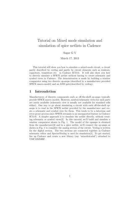
This tutorial will show you how to simulate a mixed-<strong>mode</strong> circuit, a circuit<br />
partly described by verilog <strong>and</strong> partly by circuit elements such as resistors,<br />
capacitors, transistors etc. <strong>in</strong> Cadence IC5141. It will also show you how<br />
to directly simulate a SPICE netlist without hav<strong>in</strong>g to create schematic <strong>and</strong><br />
symbol views <strong>in</strong> Cadence. The dem<strong>on</strong>strati<strong>on</strong> is made by build<strong>in</strong>g a w<strong>in</strong>dow<br />
comparator us<strong>in</strong>g two discrete op-amps (described by a manufacturer provided<br />
SPICE macro-<strong>mode</strong>l) <strong>and</strong> an AND gate(described by verilog).<br />
1 Introudcti<strong>on</strong><br />
Manufacturers <strong>of</strong> discrete comp<strong>on</strong>ents such as <strong>of</strong>f-the-shelf op-amps typically<br />
provide SPICE macro <strong>mode</strong>ls. However, symbol/schematic views for such parts<br />
are rarely available (schematic view is usually not available for st<strong>and</strong>ard cells<br />
either). One way to go about simulat<strong>in</strong>g a circuit with such <strong>of</strong>f-the-shelf opamps<br />
is to read <strong>in</strong> the SPICE netlist provided by the manufacturer <strong>and</strong> create<br />
a schematic <strong>and</strong> symbol view for them. This tends to be a laborious <strong>and</strong><br />
error-pr<strong>on</strong>e process s<strong>in</strong>ce SPICE stream<strong>in</strong> is an unsupported feature <strong>in</strong> Cadence<br />
IC5141. A simpler approach is to simulate the netlist directly, without creat<strong>in</strong>g<br />
schematic or symbol views[2]. In this tutorial, we’ll build <strong>and</strong> simulate a<br />
w<strong>in</strong>dow comparator shown <strong>in</strong> Fig. 1. The <strong>mode</strong>l <strong>of</strong> the opamps is obta<strong>in</strong>ed<br />
from the manufacturer[3] <strong>and</strong> <strong>in</strong> a <strong>spice</strong> netlist, we’ll c<strong>on</strong>nect the op-amps as<br />
shown <strong>in</strong> Fig. 1 to complete the analog secti<strong>on</strong> <strong>of</strong> the circuit. Verilog is written<br />
for the digital secti<strong>on</strong>. The two secti<strong>on</strong>s are c<strong>on</strong>nected together <strong>in</strong> Cadence<br />
schematic editor <strong>and</strong> SpectreVerilog is used for simulati<strong>on</strong>[1]. To get started,<br />
fire up Cadence <strong>and</strong> create a new library (say “mixedtutorial”) attached to<br />
UMC13MMRF.<br />
1
Figure 1: W<strong>in</strong>dow Comparator<br />
2 The digital secti<strong>on</strong><br />
In the library mixedtutorial, create a new cell-view ”<strong>and</strong>gate” with ”functi<strong>on</strong>al”<br />
as the View name <strong>and</strong> ”Verilog-editor” as the tool (see Fig. 2). When you click<br />
<strong>on</strong> OK, a text editor should open up. Write code for the AND gate as shown <strong>in</strong><br />
Fig. 3. Hit ESC <strong>and</strong> :wq to save <strong>and</strong> quit the editor. You may ignore warn<strong>in</strong>gs<br />
for now. When asked if you want to create a symbol view, hit yes. And voila !<br />
You’re d<strong>on</strong>e with the digital secti<strong>on</strong>.<br />
Figure 2: Creat<strong>in</strong>g a verilog cell-view<br />
2
Figure 3: Verilog view for AND gate<br />
3 The analog secti<strong>on</strong><br />
Download the <strong>spice</strong> macro<strong>mode</strong>l for AD8542 from [2] <strong>and</strong> save it to ”AD8542.spi”<br />
( I put it <strong>in</strong> /data/raiddisk/sagar1/cad/mixedtutorial/code/AD8542.spi ). We’ll<br />
name the analog secti<strong>on</strong> <strong>of</strong> the circuit <strong>in</strong> Fig. 1 as ”analogw<strong>in</strong>dow”. The<br />
”analogw<strong>in</strong>dow” subcircuit will have these ports(7 <strong>in</strong> number): AVDD, AGND,<br />
VThreshlow, VThreshhigh, V<strong>in</strong>, O1, O2. Because Cadence likes to <strong>in</strong>sert an<br />
extra reference port when <strong>spice</strong> <strong>netlists</strong> are <strong>in</strong>voked from the schematic editor,<br />
we’ll place another port which we shall call ”dummy” <strong>and</strong> never use it (This is<br />
<strong>on</strong>ly necessary for the top subckt <strong>in</strong> the <strong>spice</strong> netlist that you want to expose<br />
to the Cadence schematic editor). Now, write the c<strong>on</strong>tents <strong>of</strong> List<strong>in</strong>g 1 to a file<br />
(I put it <strong>in</strong> /data/raiddisk/sagar1/cad/mixedtutorial/code/analogw<strong>in</strong>dow.spi).<br />
The analog secti<strong>on</strong> is d<strong>on</strong>e.<br />
List<strong>in</strong>g 1: analogw<strong>in</strong>dow.spi<br />
∗ F i r s t l i n e <strong>in</strong> SPICE i s always a comment !<br />
. <strong>in</strong>clude / data / r a i d d i s k / sagar1 /cad/ m i x e d t u t o r i a l / code /AD8542 . s p i<br />
.SUBCKT analogw<strong>in</strong>dow AVDD AGND VThreshlow VThreshhigh V<strong>in</strong> O1 O2 dummy<br />
X1 V<strong>in</strong> VThreshlow AVDD AGND O1 AD8542<br />
X2 VThreshhigh V<strong>in</strong> AVDD AGND O2 AD8542<br />
.ENDS analogw<strong>in</strong>dow<br />
4 Putt<strong>in</strong>g them together<br />
Create a new schematic cell-view ”w<strong>in</strong>dowcomparator” <strong>in</strong> the library ”mixedtutorial”.<br />
Insert a comp<strong>on</strong>ent ”scasubckt” from analogLib to <strong>in</strong>stantiate the <strong>spice</strong><br />
netlist we created (see Fig. 4). When count<strong>in</strong>g the number <strong>of</strong> ports, do NOT<br />
3
<strong>in</strong>clude ”dummy” <strong>in</strong> the count. Instantiate the AND gate created with verilog<br />
<strong>in</strong> the usual way <strong>and</strong> make c<strong>on</strong>necti<strong>on</strong>s. The f<strong>in</strong>al schematic which <strong>in</strong>cludes the<br />
test voltage sources is shown <strong>in</strong> Fig. 5. Every digital IO p<strong>in</strong> has to be c<strong>on</strong>nected<br />
to someth<strong>in</strong>g ”analog” for the mixed <strong>mode</strong> simulati<strong>on</strong> to work right. To do this,<br />
add 1fF caps to all digital l<strong>in</strong>es.<br />
Figure 4: Instantiat<strong>in</strong>g a SPICE netlist <strong>in</strong> the schematic<br />
Figure 5: Completed w<strong>in</strong>dow comparator schematic with test voltage sources<br />
Now, close the schematic <strong>and</strong> create a ”c<strong>on</strong>fig” view with ”Hierarchy-editor”<br />
tool for the same cell (the <strong>on</strong>e with the schematic you just made <strong>in</strong>clud<strong>in</strong>g the<br />
SPICE netlist <strong>and</strong> AND gate <strong>in</strong>stantiated. In my case, it is ”w<strong>in</strong>dowcompara-<br />
4
tor”) as shown <strong>in</strong> Fig. 6.<br />
Figure 6: C<strong>on</strong>fig view for the mixed <strong>mode</strong> schematic<br />
Click <strong>on</strong> ”Browse” <strong>and</strong> select the schematic view <strong>of</strong> your mixed <strong>mode</strong> circuit<br />
<strong>in</strong> the library browser as shown <strong>in</strong> Fig. 7.<br />
5
Figure 7: Browse to select the mixed <strong>mode</strong> schematic<br />
Now, click <strong>on</strong> ”Use Template”. Choose ”SpectreVerilog” from the list <strong>and</strong><br />
Click OK. In the ”LibraryList” field, enter ”mixedtutorial” which is the library<br />
you are us<strong>in</strong>g for this tutorial. F<strong>in</strong>ally, the new c<strong>on</strong>fig dialog box should look<br />
similar to Fig. 8.<br />
6
Figure 8: New C<strong>on</strong>figurati<strong>on</strong> Dialog box after sett<strong>in</strong>g everyth<strong>in</strong>g<br />
In the hierarchy-editor, click View -〉 Update <strong>and</strong> then File -〉 Save <strong>and</strong> close<br />
the hierarchy editor.<br />
Open the ”c<strong>on</strong>fig” view <strong>and</strong> click <strong>on</strong> ”yes” to both for edit <strong>mode</strong>. Goto<br />
Tools, Analog Envir<strong>on</strong>ment to start the simulati<strong>on</strong>. Click Setup, Simulator <strong>and</strong><br />
choose ”SpectreVerilog” as the simulator <strong>and</strong> select the desired nets ( V<strong>in</strong> <strong>and</strong><br />
Y ) for plott<strong>in</strong>g. You’ll probably f<strong>in</strong>d that the AND gate is not work<strong>in</strong>g. This is<br />
because the logic thresholds which c<strong>on</strong>vert analog voltages to digital values <strong>and</strong><br />
vice versa are by default set to 5v logic. This can be changed by go<strong>in</strong>g to the<br />
newly opened schematic editor, <strong>Mixed</strong> Signal, Interface elements, Library. You<br />
can also change the rise time <strong>and</strong> fall time <strong>of</strong> digital signals be<strong>in</strong>g c<strong>on</strong>nected to<br />
analog comp<strong>on</strong>ents here.<br />
5 Simulati<strong>on</strong> results<br />
Figure 9: W<strong>in</strong>dow comparator detects when V<strong>in</strong> is between 1 <strong>and</strong> 1.5v<br />
7
6 C<strong>on</strong>clusi<strong>on</strong><br />
This tutorial dem<strong>on</strong>strated the simulati<strong>on</strong> <strong>of</strong> a mixed signal circuit. Simulat<strong>in</strong>g<br />
a SPICE netlist directly without creat<strong>in</strong>g schematic/symbol views was shown.<br />
This is particularly useful when simulat<strong>in</strong>g SPICE macro <strong>mode</strong>ls <strong>of</strong> <strong>of</strong>f-the-shelf<br />
comp<strong>on</strong>ents <strong>and</strong> st<strong>and</strong>ard cells for which schematic/symbol view is unavailable.<br />
References<br />
[1] J.Wade, Cadence <strong>Mixed</strong> Signal <str<strong>on</strong>g>Tutorial</str<strong>on</strong>g>, http://bit.ly/YhkSmd<br />
[2] T.Wilsey, How to Simulate a Subcircuit <strong>in</strong> Spectre, http://bit.ly/p1HxaW<br />
[3] Spice Macro-<strong>mode</strong>l for AD8542, http://bit.ly/Xho4ux<br />
8