Interactive Global Illumination Based on Coherent Surface Shadow ...
Interactive Global Illumination Based on Coherent Surface Shadow ...
Interactive Global Illumination Based on Coherent Surface Shadow ...

Create successful ePaper yourself
Turn your PDF publications into a flip-book with our unique Google optimized e-Paper software.
Alternatively, a hemi-cube could be used and rotated to the tangent<br />
frame at each surface positi<strong>on</strong>. We did not c<strong>on</strong>sider this opti<strong>on</strong><br />
because of the lower coherence of depth values for a pixel due to the<br />
rotati<strong>on</strong> of the depth cube map. To avoid depth fighting problems,<br />
we use linear depth values [2]. In this way, we can use a small value<br />
for the near plane without precisi<strong>on</strong> problems for larger depth values.<br />
Some small surface details in fr<strong>on</strong>t of the near plane can be lost, here<br />
normal mapping is used to simulate them. The far plane is adjusted<br />
to the maximum diameter of the scene.<br />
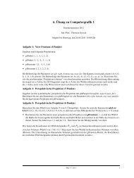
3.2.2 Visibility Query<br />
A visibility query works as follows (see Fig. 4): To test if the<br />
point p i (3D positi<strong>on</strong> of the current fragment) is in shadow of an<br />
arbitrary sender point p j , the depth values at p j are determined. After<br />
projecting p i in the coordinate system of p j , the pixel positi<strong>on</strong> q and<br />
the depth value z xy are known. There is an occlusi<strong>on</strong> between p i and<br />
p j if z xy is smaller than q z (the depth value of p i in the coordinate<br />
system of p j ). Because of the discretizati<strong>on</strong> (depth map resoluti<strong>on</strong><br />
and cube map positi<strong>on</strong>s), banding artifacts can appear in shadow<br />
regi<strong>on</strong>s. The same generalized percentage closer filtering (PCF)<br />
used with CSMs can be used to improve shadow quality.<br />
p <br />
z <br />
q<br />
p <br />
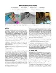
Figure 5: Illuminated atlas for the Cornell Box scene.<br />
positi<strong>on</strong>. See left of Figure 6 and Figure 7 for a visualizati<strong>on</strong> of this<br />
process.<br />
The Spiral strategy moves al<strong>on</strong>g the border of each chart, marking<br />
each visited texel. This can be thought of as walking al<strong>on</strong>g left hand<br />
side of the border as l<strong>on</strong>g as possible. If there is no free texel in<br />
the neighborhood, we step back recursively until a free neighbor<br />
is available. Typically, this leads to a spiral-shape where texels are<br />
visited from outside to inside. As before, a depth cube map is created<br />
for the positi<strong>on</strong> associated with each texel. The right side of Figure 6<br />
and Figure 7 show this traversal strategy.<br />
1<br />
1<br />
3 3<br />
Figure 4: CSSM visibility test: To test visibility from the point p j to<br />
p i , we project p i into the cube map of p j giving pixel q and compare<br />
it’s depth z xy to the depth of p i .<br />
2<br />
2<br />
3.2.3 <strong>Coherent</strong> Depth Cube Maps through Atlas Traversal<br />
Our goal is to find a sequence of depth cube maps with a minimal<br />
amount of storage after compressi<strong>on</strong>. Similar to the CSM, coherence<br />
between the depth maps is an important prec<strong>on</strong>diti<strong>on</strong> for a<br />
good compressi<strong>on</strong>. Finding a coherent sequence can therefore be<br />
visualized as moving a depth cube map al<strong>on</strong>g the surface of an object<br />
in small steps such that <strong>on</strong>ly small changes in the depth values occur,<br />
thereby visiting each locati<strong>on</strong> of the surface exactly <strong>on</strong>ce. Such a<br />
parametrizati<strong>on</strong> of the surface of an arbitrary complex object is not<br />
a trivial task. A comm<strong>on</strong> way to parameterize the surface of an<br />
object is to use a texture atlas, which can either be created manually<br />
or automatically (we use Autodesk 3ds Max). The atlas is a large<br />
texture which c<strong>on</strong>tains the following informati<strong>on</strong> for each texel: 3D<br />
positi<strong>on</strong>, normal, area, radiance and BRDF parameters (eg. diffuse<br />
color, roughness, glossiness).<br />
An atlas c<strong>on</strong>sists of so-called charts describing c<strong>on</strong>nected regi<strong>on</strong>s<br />
of the object (see Fig. 5 for an example). Moving from <strong>on</strong>e texel to<br />
its neighbour is likely to be coherent if we stay inside a chart. We<br />
therefore avoid to simply visit all texels inside the atlas, and instead<br />
develop two strategies for a coherent traversal where <strong>on</strong>e chart after<br />
the other is visited: Zig-Zag and Spiral.<br />
For the Zig-Zag strategy we first determine the bounding box of the<br />
(first) chart. We then visit all texels inside the box in a zig-zag pattern<br />
from top to bottom. For each texel, we retrieve the corresp<strong>on</strong>ding 3D<br />
positi<strong>on</strong> and generate a depth cube map for it. If a texel is undefined<br />
(or bel<strong>on</strong>gs to a different chart), we skip it. After visiting all texels<br />
of <strong>on</strong>e chart, we move to the next chart which has the closest 3D<br />
Figure 6: <strong>Coherent</strong> traversal in an atlas with three charts: A traversal<br />
strategy is used for each chart. Left: Zig-Zag. Right: Spiral.<br />
Figure 7: Traversing the Cornell box (left: zig-zag, right: spiral)<br />
and the Cornell Church with a depth cube map in a coherent order.<br />
Resoluti<strong>on</strong> is artificially low to make the path more visible.<br />
We do not use the Hilbert pattern (used for CSM traversal) because it<br />
is not suited for arbitrary shaped charts. If there is no parametrizati<strong>on</strong><br />
available, we resort to a traversal that greedily walks a number of<br />
random samples that were distributed evenly across the surface.<br />
3.3 Moving Objects<br />
In the case of moving objects, each object c<strong>on</strong>tains its own CSSM<br />
and an additi<strong>on</strong>al CSM. After a rigid transformati<strong>on</strong>, the same visibility<br />
test as described in Sec. 3.2.2 can still be performed for two<br />
points <strong>on</strong> the same object. To test if there is an occluder between