

Mitsubishi FX-PLC Addressing, Instruction & Device List Quick ...
Mitsubishi FX-PLC Addressing, Instruction & Device List Quick ...
Mitsubishi FX-PLC Addressing, Instruction & Device List Quick ...

Create successful ePaper yourself
Turn your PDF publications into a flip-book with our unique Google optimized e-Paper software.
<strong>Mitsubishi</strong> <strong>FX</strong>1S, <strong>FX</strong>3G & <strong>FX</strong>3U <strong>PLC</strong><br />
Basic <strong>Addressing</strong>, <strong>Instruction</strong>, <strong>Device</strong> <strong>List</strong> <strong>Quick</strong> Reference<br />
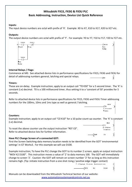
Inputs:<br />
The input device numbers are octal with prefix of ‘X’. Example: X0 to X7, X10 to X17, X20 to X27 etc.<br />
Outputs:<br />
The output device numbers are octal with prefix of ‘Y’. For example: Y0 to Y7, Y10 to Y17, Y20 to Y27 etc.<br />
Internal Relays / Flags:<br />
Commence at M0. See attached device lists in performance specifications for <strong>FX</strong>1S, <strong>FX</strong>3G and <strong>FX</strong>3U for<br />
detail of addressing numbers general, latching and special relays.<br />
Timers:<br />
These are on-delay. Example instruction; apply to an output coil “T0 K50” for a 5 second timer. The ‘K’ is<br />
constant (i.e) decimal. T0 is a 100 millisecond timer, thus setting it to a ‘constant of 50’ provides for 5<br />
seconds.<br />
Refer to attached device lists in performance specifications for <strong>FX</strong>1S, <strong>FX</strong>3G and <strong>FX</strong>3U Timer addressing<br />
numbers for the 100ms, 10ms and 1ms type as well as general / latching.<br />
Counters:<br />
Example instruction; apply to an output coil “C0 K10” for a 10 pulse count-up counter. The ‘K’ is constant<br />
(i.e) decimal.<br />
To reset the above counter use the output instruction “RST C0”.<br />
Refer to attached device lists for further information.<br />
Have <strong>PLC</strong> Change Screen of a connected GOT:<br />
First the Screen Switching data memory location needs to be identified from the GOT ‘environmental<br />
settings’ in GT Works3. For this example we will use D100.<br />
Example instruction; To have the <strong>PLC</strong> change the GOT to its number 2 screen, apply an output instruction<br />
“MOV K2 D100”. This instruction moves a value of ‘2’ to data memory 100. The GOT will immediately<br />
change to screen ‘2’. Caution: the GOT will remain on screen number ‘2’ for as long as this instruction<br />
remains high. (Tip: initiate instruction from a one shot rising / positive edge trigger contact)<br />
Manuals can be downloaded from the <strong>Mitsubishi</strong> Technical Section of our website:<br />
www.automationsystemsandcontrols.net.au
<strong>FX</strong>1S
<strong>FX</strong>1S
<strong>FX</strong>3G
<strong>FX</strong>3G
<strong>FX</strong>3U
<strong>FX</strong>3U
<strong>FX</strong>3U


