

Pluto Safety PLC (4.3Mb) - Automation Systems and Controls
Pluto Safety PLC (4.3Mb) - Automation Systems and Controls
Pluto Safety PLC (4.3Mb) - Automation Systems and Controls
- No tags were found...

You also want an ePaper? Increase the reach of your titles
YUMPU automatically turns print PDFs into web optimized ePapers that Google loves.
ContentsPage1Why you should use the <strong>Pluto</strong> safety <strong>PLC</strong>________________________________2:2<strong>Pluto</strong> safety <strong>PLC</strong>______________________________________________________2:6• <strong>Pluto</strong> without databus___________________________________________________2:8• <strong>Pluto</strong> with databus____________________________________________________ 2:12• Certification_________________________________________________________2:15• Example – Robot cell with <strong>Pluto</strong>___________________________________________2:18<strong>Pluto</strong> gateway• Gate P2-Profibus DP _ ________________________________________________ 2:26• Gate D2-DeviceNet _ _________________________________________________ 2:28• Gate C2-CANOpen __________________________________________________ 2:30• Gate E2-Profinet, Ethernet/IP, Modbus TCP _________________________________ 2:32Safe Encoder______________________________________________________ 2:3423456789101112Descriptions <strong>and</strong> examples in this book show how the products work <strong>and</strong> can be used. This does not mean that they can meet the requirements forall types of machines <strong>and</strong> processes. The purchaser/user is responsible for ensuring that the product is installed <strong>and</strong> used in accordance with theapplicable regulations <strong>and</strong> st<strong>and</strong>ards. We reserve the right to make changes in products <strong>and</strong> product sheets without previous notice. For the latestupdates, refer to www.jokabsafety.com. 2011.ABB2:11314
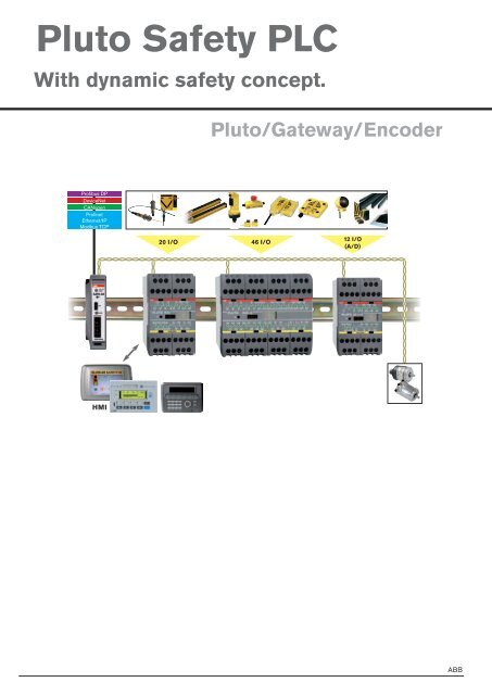
Why you shouldhave <strong>Pluto</strong> safety<strong>PLC</strong>'s.– for simplifying the design of <strong>and</strong> changes to safety systems!<strong>Pluto</strong> is an ”All-Master” safety <strong>PLC</strong> concept, that simplifiesthe design of safety systems <strong>and</strong> achieves the highestsafety level PL e according to EN ISO 13849-1 <strong>and</strong> SIL 3according to EN 62061 <strong>and</strong> EN 61508. The key differencebetween <strong>Pluto</strong> <strong>and</strong> conventional safety <strong>PLC</strong>´s is that thereis no "Master-Slave" relationship between the control unitsconnected to the safety bus. Each <strong>Pluto</strong> is a 'Master' unit<strong>and</strong> can see the other <strong>Pluto</strong>s' inputs <strong>and</strong> outputs, <strong>and</strong> canthereby make decisions about its own safety environment.This concept enables simple communication, programming<strong>and</strong> changes to the safety system. With the use of a 'Gateway'device, a <strong>Pluto</strong> can communicate with other bus systems<strong>and</strong> thereby form part of a larger network. Gateway units areavailable for several different bus systems, such as Profibus,CanOpen, DeviceNet, Profinet, Ethernet/IP <strong>and</strong> ModbusTCP. With a <strong>Pluto</strong> AS-i, both safety slaves <strong>and</strong> st<strong>and</strong>ardslaves can be h<strong>and</strong>led.<strong>Pluto</strong> offers an economic solution for both single machines<strong>and</strong> for major machine systems.Our solution with All-Master<strong>Pluto</strong> All-Master<strong>Pluto</strong> – All Master20 I/O + 20 I/O + 20 I/O<strong>Pluto</strong> All-Master<strong>Pluto</strong> All-Master4 + 4 + 4Traditional safety <strong>PLC</strong>12 I/O+31 AS-i safetynodesMasterSafe bus4<strong>Pluto</strong> AS-iSlaves46 I/O + 20 I/O6 + 42:2ABB
<strong>Safety</strong> <strong>PLC</strong><strong>Pluto</strong>Approvals:TÜV Rheinl<strong>and</strong>Control of:<strong>Safety</strong> products in dynamic<strong>and</strong> static circuitsElectrically controlledactuators such ascontactors, valves, motorsIndicators <strong>and</strong> buttonsFeatures:<strong>Pluto</strong> <strong>Safety</strong> <strong>PLC</strong> facilitates the design of yoursafety systems<strong>Pluto</strong> is an All-Master system for dynamic <strong>and</strong> static safetycircuits where inputs <strong>and</strong> other information are shared overthe bus. Multiple safety sensors can be connected to asingle input <strong>and</strong> still achieve the highest level of safety. <strong>Pluto</strong>has inputs suited for every safety product on the market,<strong>and</strong> each input function is configured in the accompanyingsoftware <strong>Pluto</strong> Manager.Besides failsafe inputs (I) <strong>Pluto</strong> has a number of failsaferelay <strong>and</strong> transistor outputs (Q). On every <strong>Pluto</strong> unit thereis also a possibility of using a number of terminals asfailsafe inputs, non-failsafe outputs or both in <strong>and</strong> outputsimultaneously (IQ). The characteristics of the terminals areeasily configured in <strong>Pluto</strong> Manager.A <strong>Safety</strong>-<strong>PLC</strong> for eachsystem partDispersed constructions ofmachinesGreat flexibilityUp to 10 sensors in seriesconnected to one inputSoftware <strong>Pluto</strong> Manager freeof chargeH<strong>and</strong>les conventionalcircuit breakers as well asdynamical sensorsCustom made safety bus<strong>Safety</strong> in large <strong>and</strong> small systems<strong>Pluto</strong> models without bus communication are st<strong>and</strong> aloneunits <strong>and</strong> are therefore perfectly suited for smaller systemsthat do not require communication with other <strong>Pluto</strong> units orgateways. <strong>Pluto</strong> models with bus communication can beconnected to the <strong>Pluto</strong> bus where up to 32 <strong>Pluto</strong> units caninteract <strong>and</strong> control large as well as small safety systems.The fact that <strong>Pluto</strong> is an All-Master system means that each<strong>Pluto</strong> unit controls their outputs locally, while it is as easy toread other <strong>Pluto</strong> units' inputs as their own.Specifically for <strong>Pluto</strong> A20 is that it is equipped with ananalogue input for current measurement, which can beused for e.g. monitoring of muting lamps.<strong>Pluto</strong> is primarily designed to satisfy the requirements ofEU Machinery Directive (2006/42/EG) regarding safety incontrol systems, but the system can also be used in otherareas as in the process industry, boiler plants etc whichhave similar requirements.2:6ABB
Technical info - <strong>Pluto</strong>Dynamic signal+24 V0 VA dynamic signal makes it possible to achieve the highestlevel of safety with only one conductor. By transmitting asquare wave <strong>and</strong> then evaluating the signal when it comesback to the controller you achieve the redundancy required.The signal is inverted once at each safety sensor (ifthe protection is OK) which makes it possible to detectshort circuits across a sensor. When the signal switchesbetween high (+24 V) <strong>and</strong> low (0V) it can be evaluated <strong>and</strong>tested about 200 times per second.<strong>Pluto</strong> can generate three unique dynamic signals; Apulse, B pulse or C pulse. Short circuits between twodifferent dynamic signals are detected whenever the signalthat is created is different from the expected signal in<strong>Pluto</strong>. The kind of signal <strong>Pluto</strong> expects at the input terminalis determined in <strong>Pluto</strong> Manager (A, B or C pulse <strong>and</strong> if thesignal should be inverted or not).Static signalStatic signals (+24 V or 0 V) can be connected to all inputson <strong>Pluto</strong>. The kind of signal <strong>Pluto</strong> expects at the inputterminal is determined in <strong>Pluto</strong> Manager. To achieve atwo-channel structure according to EN ISO 13849-1 youneed two inputs.OSSD-signal+24 V0 VThere are safety products with internal monitoring of dualOSSD signals (the device detects its own faults rather than<strong>Pluto</strong> doing this). From these devices, at least one of the twosignals is connected to an I-input in <strong>Pluto</strong>, i.e. both signalsmust not be connected to the IQ-terminals. The terminalblocks are then configured in <strong>Pluto</strong> Manager to expect staticinputs (OSSD signals are filtered internally in <strong>Pluto</strong>).IQ – individual failsafe inputs <strong>and</strong> non-failsafeoutputsThe IQ terminals can be used either as individual failsafeinput or non-failsafe output (e.g. for indicator light or statussignal). The terminal blocks can also be used as both input<strong>and</strong> output simultaneously, which is useful for example forpush buttons (input) with indicator light (output). This functionis designed primarily for reset buttons to reduce thenumber of used terminal blocks on the controller.I - individual failsafe inputsAll inputs are individually failsafe as each input is connectedseparately to both processors in <strong>Pluto</strong>. In order to maintainthe redundancy required for two-channel structure <strong>and</strong> thehighest level of safety, the dynamic signal must be used.When using static signals, two inputs must be used to achievetwo-channel structure. The expected signal to theterminals blocks is determined in <strong>Pluto</strong> Manager (static ordynamic signal).Q - individual failsafe outputsAll Q outputs are individually safe <strong>and</strong> are independentlyprogrammable. There are both relay outputs <strong>and</strong> transistoroutputs.Transistor outputs (-24 VDC)The transistor outputs are just like the relay outputs, thatis individually safe <strong>and</strong> independently programmable. However,the transistor outputs are different from the relayoutputs as the internal connection provides the nominalinput voltage -24 VDC, which is primarily intended for controllingelectromechanical components such as contactors<strong>and</strong> valves. As -24 VDC is a unique signal in the majorityof electrical cabinets <strong>and</strong> the fact that the output is monitoredby <strong>Pluto</strong>, short circuits with other potentials can bedetected right away.<strong>Pluto</strong>-busThe <strong>Pluto</strong>-bus is a CAN-bus with its own safety protocol.The bus cable can be up to 600 m long at the minimumbus speed, <strong>and</strong> up to 150 m at 400 kb/s. The bus canbe both extended <strong>and</strong> connected to other types of busesthrough gateways.12345678910<strong>Pluto</strong> Manager <strong>and</strong> IDFIX<strong>Pluto</strong> managerThe <strong>Pluto</strong> Manager is a freeware for fast, easy <strong>and</strong> safeprogramming of the <strong>PLC</strong> program for <strong>Pluto</strong>. The programminglanguage used is ladder, which is supplemented withTÜV-approved function blocks for many common features.The software can also be used to configure <strong>Pluto</strong>'s terminalblocks, e.g. to specify the IQ terminals that serve as inputsor outputs, <strong>and</strong> if the controller should expect a static ordynamic signal. <strong>Pluto</strong> Manager can be downloaded fromJokab <strong>Safety</strong>'s website.IDFIXIDFIX is a identification circuit that is unique to each deviceon the <strong>Pluto</strong> bus. It includes an identification code <strong>and</strong>makes it possible to distribute a <strong>PLC</strong> program in the network.There are four different versions: R, RW, DATA <strong>and</strong>PROG. In addition to the identification code, DATA mayalso include safety codes from the AS-i nodes in an AS-isystem. PROG includes the current <strong>PLC</strong> program <strong>and</strong> isused with single-<strong>Pluto</strong> for program distribution. IDFIX isconnected between the input terminals ID <strong>and</strong> 0V.111213ABB2:714
<strong>Pluto</strong> without a safety busSingle <strong>Pluto</strong> controls <strong>and</strong> monitors safety for local systems- large aswell as small systems20/46 I/O<strong>Pluto</strong> S20 <strong>Pluto</strong> S46 BT51PatentedsolutionPatentedsolutionConnector expansionSeveral expansion relays canbe connected to a single <strong>Pluto</strong>safety output while retainingthe safety level.HMIA HMI-terminal iseasy to connect toone or more <strong>Pluto</strong>sthrough the Modbuscontact.<strong>Pluto</strong> ManagerA free of charge softwareis available on our website.The <strong>Pluto</strong> S20 <strong>and</strong> <strong>Pluto</strong> S46 versions are safety <strong>PLC</strong>'s thatare designed for safety <strong>and</strong> protection products installedlocally on a machine. With a wide range of connectivityoptions, a lot of protection is integrated into a <strong>PLC</strong> whichin turn controls, for example, one or more safe outputs ina qualified manner without risking a dangerous situation.Using an expansion relay, such as BT50, the number ofsafe outputs in <strong>Pluto</strong> can be exp<strong>and</strong>ed. The connectionwill then be made as shown in the figure. If IDFIX PROG isused for single-<strong>Pluto</strong>, there is the option of copying a <strong>PLC</strong>program via the identification circuit over to <strong>Pluto</strong> withouthaving to connect a computer.A1X424VDCType: BT50Connection example of a contactexpansion with <strong>Pluto</strong>2:8ABB
Technical data - generalManufacturer:Colour:Technical data - typespecificABB AB/Jokab <strong>Safety</strong>, SwedenGreyOperating voltage: 24V DC ±15%Installation:Electrical insulation:35 mm DIN railLevel of safety:EN 954-1 Kat. 4EN ISO 13849-1 PL e/kat. 4EN 61508 SIL 3EN 62061 SIL 3Category II in accordance withIEC 61010-1PFH dRelay output 2,00×10 -9Transistor output 1,50×10 -9Type:+24 V (for PNP sensors), IQalso configurable as nonfailsafeoutputsCurrent at 24 V5.1 mAMax. overvoltage27 V continuousSafe outputs QQ2–Q3:Output voltage toleranceTransistor, –24VDC, 800 mASupply voltage - 1,5 V at800 mAQ0, Q1, (Q4, 5): Relay outputsAC-1: 250 V/1,5 AAC-15: 250 V/1,5 ADC-1: 50 V/1,5 ADC-13: 24 V/1,5 ANon-failsafe outputs QType:Max. current/output:Transistor +24V, PNP "opencollector" also configurable asfailsafe inputs800 mATemperatureAmbient temperature:Storage <strong>and</strong> transport:Response timesDyn. A or static input to relayoutput:Dyn. A or static input totransistor output:Dyn. B or Dyn. C input torelay output:Dyn. B or Dyn. C input totransistor output:Software setting "NoFilt".Additional Response timesDatabus between <strong>Pluto</strong> unitsDatabus between <strong>Pluto</strong> unitson error–10˚C to +50˚C–25˚C to +55˚C
I/O Overview - <strong>Pluto</strong> without a safety busIDFIXID:I..IQ..Connection for identifier, which has a unique ID number that can be read by the system.<strong>Safety</strong> inputs (24 VDC) that are individually secure. This means that the highest level of safety can beachieved with only one input if ABB Jokab <strong>Safety</strong> dynamic safety components are used.Otherwise two inputs are required for each safety function.I/O that can be used for safety inputs or signal outputs, e.g. to indicate or control functions that are notsafety-related. For IQ.. as safety inputs, refer to I..Q0, Q1: Failsafe relay outputs that are individually failsafe <strong>and</strong> individually programmable.Q2, Q3: Failsafe transistor outputs (-24 VDC) that are individually failsafe <strong>and</strong> individually programmable.Intended for electro-mechanical components such as contactors <strong>and</strong> valves.Q4, Q5 Failsafe relay outputs with common potential that are individually failsafe <strong>and</strong> individually programmable.2:10ABB
Input connectionThe system offers solutions for both single <strong>and</strong> two-channel safety devices. In order to monitor wiring short-circuitsit is possible to use up to three different dynamic signals <strong>and</strong> static voltage (+24 V) tosupply the inputs. The inputs are then programmed to only accept one of the signal types.In a two-channel system both channels will be measured, using two different signals. The system will thereby beable to detect a short-circuit between the channels.In a single channel system the dynamic signal is modified at each sensor. A short-circuit between the input <strong>and</strong>the output of the sensor will be detected at the <strong>Pluto</strong> input. PL e according to EN ISO 13849-1 can thus beachieved by using only one channel <strong>and</strong> one input.1234Emergencystop withTinaSpot lightbeamEden sensor5Emergencystop withTina6Two-channel systemInput connection alternative in accordance with PL e EN ISO 13849-1.Single channel dynamic system78Reset button that uses the combined input <strong>and</strong> output facilityResetting with a lampinput/outputBoth a lamp <strong>and</strong> a pushbutton can be connected tothe same terminal. This function is for resetting safetydevices <strong>and</strong> to reduce the number of I/Os used.(Current monitoring)910111213ABB2:1114
<strong>Pluto</strong> with a safety bus<strong>Pluto</strong> models with a safety bus controls <strong>and</strong> monitors safety for dispersed systems– large aswell as small systems.Profibus DPDeviceNetCANopenProfinetEthernet/IPModbus TCP20/46 I/OGatewayfor twoway bus communicationbetween<strong>Pluto</strong> <strong>and</strong> othercontrolsystems.HMIA HMI-terminal iseasy to connect toone or more <strong>Pluto</strong>sthrough the Modbuscontact.Absolutgivare8 single- or multiturnabsolute encoders can beconnected.<strong>Pluto</strong> ManagerA free of charge softwareis available on our website.<strong>Pluto</strong> versions with bus have the same properties as single-<strong>Pluto</strong> unlike bus communication. With the help of the <strong>Pluto</strong>busnetworks can be created with multiple <strong>Pluto</strong>s in interaction.Gateways can be connected to the <strong>Pluto</strong> bus forcommunication with other systems. The gateway modelsGATE D2 <strong>and</strong> C2 can also be used as an extension of thebus cable to extend the <strong>Pluto</strong> network. The fact that <strong>Pluto</strong> isan All-master system means that each <strong>Pluto</strong> device controlsits outputs locally, while it is just as easy to read the inputsof other <strong>Pluto</strong>-units as it is to read its own. It is also easy toboth read <strong>and</strong> write to global memory locations availableacross the <strong>Pluto</strong> bus. The <strong>PLC</strong> program is created usingthe <strong>Pluto</strong> Manager freeware <strong>and</strong> is distributed to all <strong>Pluto</strong>units. You can also connect speed <strong>and</strong> position sensorsvia the <strong>Pluto</strong> bus.Current monitoring (<strong>Pluto</strong> A20 only)<strong>Pluto</strong> A20 can monitor the current through the IQ16 <strong>and</strong>IQ17 outputs. The function is designed for, but not limitedto, ensuring that the muting lamps are working. Thehardware for current monitoring is not designed with individualredundancy, which means that the function must beused dynamically if it is to be used in a safety function. Thismeans that the current must be read <strong>and</strong> evaluated bothwhen the output is enabled <strong>and</strong> disabled.2:12ABB
ABBTechnical data - generalManufacturer:Colour:ABB AB/Jokab <strong>Safety</strong>, SwedenGreyOperating voltage: 24V DC ±15%Installation:Electrical insulation:35 mm DIN rail<strong>Safety</strong> levelEN 954-1 Kat. 4EN ISO 13849-1 PL e/kat. 4EN 61508 SIL 3EN 62061 SIL 3PFH dRelay output 2,00×10 -9Transistor output 1,50×10 -9Failsafe inputs I & IQType:Current at 24 VMax. overvoltageSafe outputs QQ2–Q3:Output voltage toleranceCategory II in accordance withIEC 61010-1+24 V (for PNP sensors), IQalso configurable as nonfailsafeoutputs5.1 mA27 V continuousTransistor, –24VDC, 800 mASupply voltage - 1,5 V at800 mAQ0, Q1, (Q4, 5): Relay outputsAC-1: 250 V/1,5 AAC-15: 250 V/1,5 ADC-1: 50 V/1,5 ADC-13: 24 V/1,5 ANon-failsafe outputs QType:Max. current/output:Technical data -type-specificTransistor +24V, PNP "opencollector" also configurable asfailsafe inputs800 mA<strong>Pluto</strong> A2020 I/OCurrent monitoring<strong>Pluto</strong> safety busMax number of <strong>Pluto</strong> units onthe databus: 32Databus type:CANDatabus speeds: 100, 125, 200, 250, 400, 500,800, 1000 kb/sDatabus cable length: Up to 600 m, 150 m at 400kb/sTemperatureAmbient temperature:Storage <strong>and</strong> transport:Response timesDyn. A or static input to relayoutput:Dyn. A or static input totransistor output:Dyn. B or Dyn. C input torelay output:Dyn. B or Dyn. C input totransistor output:Software setting "NoFilt".Additional Response timesDatabus between <strong>Pluto</strong> unitsDatabus between <strong>Pluto</strong> unitson error <strong>Pluto</strong> B1616 I/ONon-failsafe outputs–10˚C to +50˚C–25˚C to +55˚C
I/O Overview - <strong>Pluto</strong> with a safety busIDFIXID:I..IQ..Connection for identifier, which has a unique ID number that can be read by the system.<strong>Safety</strong> inputs (24 VDC) that are individually secure. This means that the highest level of safety can beachieved with only one input if ABB Jokab <strong>Safety</strong> dynamic safety components are used.Otherwise two inputs are required for each safety function.I/O that can be used for safety inputs or signal outputs, e.g. to indicate or control functions that are notsafety-related. For IQ.. as safety inputs, refer to I..Q0, Q1: Failsafe relay outputs that are individually failsafe <strong>and</strong> individually programmable.Q2, Q3: Failsafe transistor outputs (-24 VDC) that are individually failsafe <strong>and</strong> individually programmable. Intendedfor electro-mechanical components such as contactors <strong>and</strong> valves.Q4, Q5 Failsafe relay outputs with common potential that are individually failsafe <strong>and</strong> individually programmable.2:14ABB
Certificates1234567Internet support - <strong>Pluto</strong>Our web site has a section dedicated to <strong>Pluto</strong> customers, offeringcontinuously updated product support. The <strong>Pluto</strong> customersite offers:• E-mail support directly linked to our <strong>Pluto</strong> specialists• Hardware manuals• The <strong>Safety</strong> Manual, with the most important safety requirements• Programming manual• Gateway manual• Function block descriptions• Common questions <strong>and</strong> answers• <strong>Pluto</strong> Manager installation file, programming tools• <strong>Pluto</strong> OS, files to update system software• Confirmation of compliance8910111213ABB2:1514
APPLICATION EXAMPLERobot cell with <strong>Pluto</strong>Description:The example describes a processing machine served by arobot. The machine safety system consists of one (<strong>Pluto</strong> 1)to which all protection has been connected. The robot hasbeen equipped with a (<strong>Pluto</strong> 0) to which the cell protectionhas been connected. The <strong>Pluto</strong> for the machine has beenconnected via a databus cable to the robot's <strong>Pluto</strong> so thatcommon functions, such as emergency stop, can be usedby the whole cell.Function:Emergency stop takes priority <strong>and</strong> will stop both the machine<strong>and</strong> the robot. The machine hatch acts as the zonedivider, when the hatch is closed the machine forms onezone <strong>and</strong> the robot another zone. When the machine hatchis open, both the machine <strong>and</strong> the robot belong to thesame zone. If the door is opened when the machine hatchis open, the machine <strong>and</strong> the robot will both stop, but if themachine hatch is closed, only the robot will be stopped.After the door has been opened, the system must be resetby means of the reset button on the outside of the door.Emergency stop is reset when the pressed-in button ispulled out. NOTE. The cell operating cycle must not howeverstart immediately on resetting the emergency stop orthe door.2:16ABB
Electrical connections12345678910111213ABB2:1714
APPLICATION EXAMPLE<strong>Pluto</strong> 0 settings – Robot cabinet<strong>Pluto</strong> 0I0.0=P0_ES1_Ch1;Emergency stop 1 channel 1 - StaticI0.1=P0_ES1_Ch2;Emergency stop 1 channel 2 - Dynamic A non-invertedI0.2=P0_Eden1;Door Eden sensor - Dynamic AI0.15=P0_LB1_In;Reset Door - Light button input - Dynamic AQ0.2=P0_AS_OK;Robot auto stop - Expansion BT50 relayQ0.3=P0_ES;Robot emergency stop - Expansion BT50 relayGM0.0=P0_ES_OK ;Emergency stop OK in <strong>Pluto</strong> 02:18ABB
<strong>Pluto</strong> 1 settings – Machine cabinet123456789<strong>Pluto</strong> 1I1.1=P2_ES1_Ch1;Emergency stop 1 channel 1 - Dynamic A non-invertedI1.2=P2_ES1_Ch2;Emergency stop 1 channel 2 -StaticI1.3=P2_IS1_Ch1;Interlocking switch channel 1 - Dynamic A non-invertedI1.4=P2_IS1_Ch2;Interlocking switch channel 2 - StaticI1.15=P2_LB1_In;Reset Hatch - Light button input - Dynamic AQ1.0=P2_ES;Machine Emergency stopQ1.1=P2_PS;Machine protective stopGM1.0=P2_ES_OK ;Emergency stop OK in <strong>Pluto</strong> 1GM1.1=P2_Hatch_OK;Hatch closed10111213ABB2:1914
APPLICATION EXAMPLE<strong>PLC</strong> code <strong>Pluto</strong> 0 – Robot cabinet1Start2 Two channel monitoring with automatic reset of emergency stop at the door.P0_ES1_Ch1I0.0P0_ES1_Ch2I0.1In1In2TC1SQP0_ES_OKGM0.0StartGM0.0=P0_ES_OK Emergency stop OK in <strong>Pluto</strong> 0I0.0=P0_ES1_Ch1Emergency stop 1 channel 1 - StaticI0.1=P0_ES1_Ch2Emergency stop 1 channel 2 - Dynamic A non-inverted3 Emergency stop of robot.When the emergency stop is actuated the robot will make an emergency stop.In order to restore safety requires the emergency stop button needs to be reset.An emergency stop from the machine panel will also emergency stop the robot.P0_ES_OKGM0.0P1_ES_OKGM1.0P0_ESQ0.3GM0.0=P0_ES_OK Emergency stop OK in <strong>Pluto</strong> 0GM1.0=P1_ES_OK Emergency stop OK in <strong>Pluto</strong> 1Q0.3=P0_ESRobot emergency stop - Expansion BT50 relay4 Auto stop of robot.When the door to the robot cell is opened the robot is auto stopped.To reset the safety the door needs to be closed <strong>and</strong> the reset button pressed <strong>and</strong> released.Note that IQ15 of the <strong>Pluto</strong> is used both as a button in <strong>and</strong> to indicate diffirent reset states.Constant light means reset is not possible, safety not ok.Flash 0.4 s high, 0.6 s low means reset is possible but not performed.No light means reset has been performed <strong>and</strong> the safety is ok.P0_Eden1I0.2In1ResetTQP0_AS_OKQ0.2P0_LB1_InI0.15NResetIndResetP0_LB1_OutQ0.15TestI0.15=P0_LB1_InI0.2=P0_Eden1Q0.15=P0_LB1_OutQ0.2=P0_AS_OKReset Door - Light button input - Dynamic ADoor Eden sensor - Dynamic AReset Door - Light button output - StaticRobot auto stop - Expansion BT50 relay2:20ABB
15 Alarm 03 - Machine hatch open.To generate User Errors (UE) a value of 200 - 299 can be written to the display of the <strong>Pluto</strong>.A check of System Register 11 (SR11) in the <strong>Pluto</strong> prioritises errors from the <strong>Pluto</strong> itself over User Errors.P1_Hatch_OKGM1.1P0_AS_OKQ0.2SR_ErrorCode=0SR0.11=0SR_<strong>Pluto</strong>Display=203SR0.10=20323GM1.1=P1_Hatch_OKQ0.2=P0_AS_OKSR0.10=SR_<strong>Pluto</strong>DisplaySR0.11=SR_ErrorCodeHatch closedRobot auto stop - Expansion BT50 relay<strong>Pluto</strong> display figure. For user error: 200+noError code46 Alarm 02 - Door open.To generate User Errors (UE) a value of 200 - 299 can be written to the display of the <strong>Pluto</strong>.A check of System Register 11 (SR11) in the <strong>Pluto</strong> prioritises errors from the <strong>Pluto</strong> itself over User Errors.P0_Eden1I0.2SR_ErrorCode=0SR0.11=0I0.2=P0_Eden1SR0.10=SR_<strong>Pluto</strong>DisplaySR0.11=SR_ErrorCode7 Alarm 01 - Emergency stop actuated.Door Eden sensor - Dynamic A<strong>Pluto</strong> display figure. For user error: 200+noError codeTo generate User Errors (UE) a value of 200 - 299 can be written to the display of the <strong>Pluto</strong>.A check of System Register 11 (SR11) in the <strong>Pluto</strong> prioritises errors from the <strong>Pluto</strong> itself over User Errors.P0_ES_OKGM0.0SR_ErrorCode=0SR0.11=0GM0.0=P0_ES_OK Emergency stop OK in <strong>Pluto</strong> 0SR0.10=SR_<strong>Pluto</strong>Display<strong>Pluto</strong> display figure. For user error: 200+noSR0.11=SR_ErrorCodeError codeSR_<strong>Pluto</strong>Display=202SR0.10=202SR_<strong>Pluto</strong>Display=201SR0.10=2015678910111213ABB2:2114
APPLICATION EXAMPLE<strong>PLC</strong> code <strong>Pluto</strong> 1 – Machine cabinet1Start2 Two channel monitoring with automatic reset of emergency stop at the machine hatch.P1_ES1_Ch1I1.1TC1SP1_ES_OKGM1.0In1QP1_ES1_Ch2I1.2In2StartGM1.0=P1_ES_OK Emergency stop OK in <strong>Pluto</strong> 1I1.1=P1_ES1_Ch1Emergency stop 1 channel 1- Dynamic A non-invertedI1.2=P1_ES1_Ch2Emergency stop 1 channel 2 - Static3 Two channel monitoring with automatic reset of interlocking switch of the machine hatch.P1_IS1_Ch1I1.3TC1SP1_Hatch_OKGM1.1In1QP1_IS1_Ch2I1.4In2StartGM1.1=P1_Hatch_OKI1.3=P1_IS1_Ch1I1.4=P1_IS1_Ch2Hatch closedInterlocking switch channel 1 - Dynamic A non-invertedInterlocking switch channel 2 - Static4 Emergency stop of machine.When the emergency stop is actuated the machine will make an emergency stop.In order to restore safety requires the emergency stop button needs to be reset.An emergency stop from the robot will also emergency stop the machine.P1_ES_OKGM1.0P0_ES_OKGM0.0P1_ESQ1.0GM0.0=P0_ES_OK Emergency stop OK in <strong>Pluto</strong> 0GM1.0=P1_ES_OK Emergency stop OK in <strong>Pluto</strong> 1Q1.0=P1_ESMachine Emergency Stop5 Monitoring of the hatch.When the hatch is opened the monitoring of the hatch is inactive.To reset the safety the hatch needs to be closed <strong>and</strong> the reset button pressed <strong>and</strong> released.Note that IQ15 of the <strong>Pluto</strong> is used both as a button in <strong>and</strong> to indicate different reset states.Constant light means reset is not possible, safety not ok.Flash 0.4 s high, 0.6 s low means reset is possible but not performed.No light means reset has been performed <strong>and</strong> the safety is ok.P1_Hatch_OKGM1.1ResetTHB_Hatch_OKM1.0In1QP1_LB1_InI1.15NResetIndResetHB_Ind_Hatch_OKM1.1Test2:22GM1.1=P1_Hatch_OKI1.15=P1_LB1_InM1.0=HB_Hatch_OKM1.1=HB_Ind_Hatch_OKHatch closedReset Hatch - Light button input - Dynamic AHelp Bit - Hatch closedHelp Bit - Indication Reset HatchABB
TestIndReset1GM1.1=P1_Hatch_OKI1.15=P1_LB1_InM1.0=HB_Hatch_OKM1.1=HB_Ind_Hatch_OK6 Light button indication of the reset of the hatch.Hatch closedReset Hatch - Light button input - Dynamic AHelp Bit - Hatch closedHelp Bit - Indication Reset HatchIf the robot cell's door is closed <strong>and</strong> reset no light indication is needed inside the cell.HB_Ind_Hatch_OKM1.1P0_AS_OKQ0.2P1_LB1_OutQ1.1523M1.1=HB_Ind_Hatch_OKQ0.2=P0_AS_OKQ1.15=P1_LB1_Out7 Protective stop of the machine.Help Bit - Indication Reset HatchRobot auto stop - Expansion BT50 relayReset Hatch - Light button output - Static4Either the hatch is closed <strong>and</strong> reset or the door to the robot cell is closed <strong>and</strong> reset.This means the cell can work with the hatch both open or closed as long as the cell's door is closed <strong>and</strong> reset.HB_Hatch_OKM1.0P0_AS_OKQ0.2P1_PSQ1.156M1.0=HB_Hatch_OKQ0.2=P0_AS_OKQ1.1=P1_PS8 Alarm 03 - Machine hatch open.Help Bit - Hatch closedRobot auto stop - Expansion BT50 relayMachine Protective Stop7To generate User Errors (UE) a value of 200 - 299 can be written to the display of the <strong>Pluto</strong>.A check of System Register 11 (SR11) in the <strong>Pluto</strong> prioritises errors from the <strong>Pluto</strong> itself over User Errors.P1_Hatch_OKGM1.1P0_AS_OKQ0.2GM1.1=P1_Hatch_OKQ0.2=P0_AS_OKSR1.10=SR_<strong>Pluto</strong>DisplaySR1.11=SR_ErrorCode9 Alarm 02 - Door open.SR_ErrorCode=0SR1.11=0Hatch closedRobot auto stop - Expansion BT50 relay<strong>Pluto</strong> display figure. For user error: 200+noError codeTo generate User Errors (UE) a value of 200 - 299 can be written to the display of the <strong>Pluto</strong>.A check of System Register 11 (SR11) in the <strong>Pluto</strong> prioritises errors from the <strong>Pluto</strong> itself over User Errors.P0_Eden1I0.2SR_ErrorCode=0SR1.11=0SR_<strong>Pluto</strong>Display=203SR1.10=203SR_<strong>Pluto</strong>Display=202SR1.10=2028910I0.2=P0_Eden1SR1.10=SR_<strong>Pluto</strong>DisplaySR1.11=SR_ErrorCodeDoor Eden sensor - Dynamic A<strong>Pluto</strong> display figure. For user error: 200+noError code1110 Alarm 01 - Emergency stop actuated.To generate User Errors (UE) a value of 200 - 299 can be written to the display of the <strong>Pluto</strong>.A check of System Register 11 (SR11) in the <strong>Pluto</strong> prioritises errors from the <strong>Pluto</strong> itself over User Errors.12ABBP1_ES_OKGM1.0SR_ErrorCode=0SR1.11=0GM1.0=P1_ES_OK Emergency stop OK in <strong>Pluto</strong> 1SR1.10=SR_<strong>Pluto</strong>Display<strong>Pluto</strong> display figure. For user error: 200+noSR1.11=SR_ErrorCodeError codeSR_<strong>Pluto</strong>Display=201SR1.10=2012:231314
<strong>Pluto</strong> gatewayGATE-P2Use:Bi-directional statusinformation from the <strong>Pluto</strong>safety <strong>PLC</strong>For ProfibusFeatures:Profibus DPDeviceNetCANopenProfinetEthernet/IPModbus TCPTwo-way communicationBuilt-in filter function, sharednetworkOnly 22.5 mm wideCan be located anywhere inthe databusCommon interface with<strong>Pluto</strong>Ready-made function blocks<strong>Pluto</strong> gateway is a unit providing two-way communicationbetween a <strong>Pluto</strong> safety <strong>PLC</strong> <strong>and</strong> other field buses.The <strong>Pluto</strong> gateway is a compact unit mounted on a DINrail, <strong>and</strong> can be connected anywhere in a <strong>Pluto</strong> safety bus.The unit has a common interface with <strong>Pluto</strong>, i.e. the samecabling, <strong>and</strong> the <strong>Pluto</strong> Manager PC program can be usedfor servicing <strong>and</strong> where necessary programming. Normally,however, all the settings are made via a DIP switches, whichmeans that programming tools are not required to put thegateway itself into operation.For programming <strong>Pluto</strong> there are ready-made functionblocks which, via a <strong>Pluto</strong> gateway, send <strong>and</strong> receive datafrom the supervisory system.Data from <strong>Pluto</strong>Via PROFIBUS a supervisory <strong>PLC</strong> system can have accessto the I/O <strong>and</strong> other variables in a <strong>Pluto</strong> safety <strong>PLC</strong>.Global I/O in a <strong>Pluto</strong> safety <strong>PLC</strong> are accessible via PROFI-BUS modules in the gateway, one module for each <strong>Pluto</strong>unit. Local data in <strong>Pluto</strong> units can be read by a "local data”module together with the <strong>PLC</strong> codes in the supervisorysystem.Data to <strong>Pluto</strong>Via PROFIBUS a supervisory <strong>PLC</strong> system can transmitnon-safety-related information to a <strong>Pluto</strong> safety <strong>PLC</strong>. A totalof 64 Boolean values <strong>and</strong> 8 different 16-bit registerscan be transmitted. Function blocks for these functions areavailable in <strong>Pluto</strong> Manager.<strong>PLC</strong> function blocksTo simplify the integration of a <strong>Pluto</strong> gateway PROFIBUSinto the supervisory <strong>PLC</strong> system, ABB Jokab <strong>Safety</strong> providesready-made function blocks for several popularbr<strong>and</strong>s of <strong>PLC</strong>. The function blocks make it easier to receive<strong>and</strong> send information to the <strong>Pluto</strong> system. The functionblocks are supplied as open units with full access forthe customer to change <strong>and</strong> add functions. These functionblocks can be obtained via the Jokab <strong>Safety</strong> web site.<strong>Pluto</strong> safety bus LED"K" buttonPC portProfibus LEDProfibus connector2:24ABB
Technical data - GATE-P2Manufacturer:Article number/orderingdata:Databuses:ABB AB/Jokab <strong>Safety</strong>, Sweden2TLA020071R8000 GATE-P2-<strong>Pluto</strong> safety bus CAN(isolated)-PROFIBUS RS485 (isolated)<strong>Pluto</strong> safety bus speeds: 100, 200, 250, 400, 500, 800<strong>and</strong> 1000 kbit/s(automatic speed detection)PROFIBUS speed:Up to 12 Mbit/s (automaticspeed detection)PROFIBUS address: Setting via DIP switches (0-99)PROFIBUS version:Connections:Status indication:DP slave, DP-V0Top, 3-pole terminal for <strong>Pluto</strong>safety bus (included)Front, st<strong>and</strong>ard 9-polePROFIBUS connection.Bottom, 2-pole terminal for 24V DC (included)<strong>Pluto</strong> safety bus statusindication via LEDPROFIBUS status indicationvia LEDOperating voltage: 24 V DC, -15% till +20%Current at 24 V:Dimensions (w x h x d):Installation:< 100 mA (recommended fuse≤6 A)22.5 x 101 x 119 mm35 mm DIN railOperating temperature(ambient): -10°C to + 55ºCTemperature, transport <strong>and</strong>storage: -25°C to + 55ºCHumidity: EN 60 204-1 50% at 40ºC(ambient 90% at 20ºC)Enclosure classification: Enclosure IP 20 - IEC 60 529Terminals IP 20 - IEC 60 529Gateway block schematic diagram - <strong>Pluto</strong> Profibus119 mm22,5 mm101 mm12345678910111213ABB 2:2514
<strong>Pluto</strong> gatewayGATE-D2Use:Bi-directional statusinformation from the <strong>Pluto</strong>safety <strong>PLC</strong>For DeviceNet <strong>and</strong> <strong>Pluto</strong>bridgeProfibus DPDeviceNetCANopenProfinetEthernet/IPModbus TCPFeatures:Two-way communicationBuilt-in filter function, sharednetworkOnly 22.5 mm wideCan be located anywhere inthe databusCommon interface with<strong>Pluto</strong>Ready-made function blocks<strong>Pluto</strong> gateway is a unit providing two-way communicationbetween a <strong>Pluto</strong> safety <strong>PLC</strong> <strong>and</strong> other field buses.The <strong>Pluto</strong> gateway is a compact unit mounted on a DINrail, <strong>and</strong> can be connected anywhere in a <strong>Pluto</strong> safety bus.The unit has a common interface with <strong>Pluto</strong>, i.e. the samecabling, <strong>and</strong> the <strong>Pluto</strong> Manager PC program can be usedfor servicing <strong>and</strong> where necessary programming. Normally,however, all the settings are made via a DIP switches,which means that programming tools are not required toput the gateway itself into operation.For programming <strong>Pluto</strong> there are ready-made functionblocks which, via a <strong>Pluto</strong> gateway, send <strong>and</strong> receive datafrom the supervisory system.Data from <strong>Pluto</strong>Via DeviceNet a supervisory <strong>PLC</strong> system can have accessto the I/O <strong>and</strong> other variables in a <strong>Pluto</strong> safety <strong>PLC</strong>. GlobalI/Os in a <strong>Pluto</strong> safety <strong>PLC</strong> are accessible via DeviceNet”implicit” messages. Local data in <strong>Pluto</strong> units can be readvia DeviceNet ”explicit” messages.Data to <strong>Pluto</strong>Via DeviceNet a supervisory <strong>PLC</strong> system can transmit nonsafety-relatedinformation to a <strong>Pluto</strong> safety <strong>PLC</strong>. A total of64 Boolean values <strong>and</strong> 8 different 16-bit registers can betransmitted (via DeviceNet ”implicit” or ”explicit” messages).Function blocks for these comm<strong>and</strong>s are available in<strong>Pluto</strong> Manager.several sections. This is particularly useful when long databuscables are needed.There is also a built-in filter function which makes it possibleto block any data that is not required for use on theother side of the bridge, which reduces the databus loadingin the other sections <strong>and</strong> thereby permits longer databuscables.ABB Robotics IRC5PLUTO GATE-D2 has support for integration into an ABBRobotics IRC5-system. The documentation that describesthis integration can be obtained via the Jokab <strong>Safety</strong> website.<strong>Pluto</strong> safety bus LED"K" buttonPC portDeviceNet LEDDeviceNet connector<strong>Pluto</strong> bridgeA GATE-D2 can also be used to advantage as a CANbridge when it is required to divide a <strong>Pluto</strong> safety bus into2:26ABB
Technical data - GATE-D2ManufacturerArticle number/orderingdata:Databuses:ABB AB/Jokab <strong>Safety</strong>, Sweden2TLA020071R8200 GATE-D2-<strong>Pluto</strong> safety bus CAN (isolated)-DeviceNet CAN (isolated)<strong>Pluto</strong> safety bus speeds: 100, 200, 250, 400, 500, 800<strong>and</strong> 1000 kbit/s(automatic speed detection)DeviceNet speeds:125, 250 <strong>and</strong> 500 kbit/s (setvia DIP switch)DeviceNet address: Setting via DIP switches (1-63)DeviceNet Version: ODVA version 2.0Connections:Status indications:Top, 3-pole terminal for <strong>Pluto</strong>safety bus (included)Front, 5-pole terminal forDeviceNet (included)Bottom, 2-pole terminal for 24V DC (included)<strong>Pluto</strong> safety bus statusindication via LEDDeviceNet MNS statusindication via LEDOperating voltage: 24 V DC, -15% till +20%Current at 24 V:Dimensions (w x h x d):Installation:< 100 mA (recommended fuse≤6 A)22.5 x 101 x 119 mm35 mm DIN railOperating temperature(ambient): -10°C to + 55ºCTemperature,transport <strong>and</strong> storage: -25°C to + 55ºCHumidity: EN 60 204-1 50% at 40ºC(ambient 90% at 20ºC)Enclosure classification: Enclosure IP 20 - IEC 60 529Terminals IP 20 - IEC 60 529119 mm22,5 mm101 mm12345678Gateway block schematic diagram - <strong>Pluto</strong> DeviceNet910111213ABB 2:2714
<strong>Pluto</strong> gatewayGATE-C2Use:Bi-directional statusinformation from the <strong>Pluto</strong>safety <strong>PLC</strong>For CANopen <strong>and</strong> <strong>Pluto</strong>bridgeProfibus DPDeviceNetCANopenProfinetEthernet/IPModbus TCPFeatures:Two-way communicationBuilt-in filter function, sharednetworkOnly 22.5 mm wideCan be located anywhere inthe databusCommon interface with<strong>Pluto</strong>Ready-made function blocks<strong>Pluto</strong> gateway is a unit providing two-way communicationbetween a <strong>Pluto</strong> safety <strong>PLC</strong> <strong>and</strong> other field buses.The <strong>Pluto</strong> gateway is a compact unit mounted on a DINrail, <strong>and</strong> can be connected anywhere in a <strong>Pluto</strong> safety bus.The unit has a common interface with <strong>Pluto</strong>, i.e. the samecabling, <strong>and</strong> the <strong>Pluto</strong> Manager PC program can be usedfor servicing <strong>and</strong> where necessary programming. Normally,however, all the settings are made via a DIP switches,which means that programming tools are not required toput the gateway itself into operation.For programming <strong>Pluto</strong> there are ready-made functionblocks which, via a <strong>Pluto</strong> gateway, send <strong>and</strong> receive datafrom the supervisory system.Data from <strong>Pluto</strong>Via CANopen a supervisory <strong>PLC</strong> system can have accessto the I/O <strong>and</strong> other variables in a <strong>Pluto</strong> safety <strong>PLC</strong>. GlobalI/Os in a <strong>Pluto</strong> safety <strong>PLC</strong> are accessible via CANopenPDO messages. Local data in <strong>Pluto</strong> units can be read viaCANopen SDO messages together with the <strong>PLC</strong> codes inthe supervisory system.Data to <strong>Pluto</strong>Via CANopen a supervisory <strong>PLC</strong> system can send nonsafety-relatedinformation to a <strong>Pluto</strong> safety <strong>PLC</strong>. A total of64 Boolean values <strong>and</strong> 8 different 16-bit registers can betransmitted (CANopen PDO or SDO messages). Functionblocks for these comm<strong>and</strong>s are available in <strong>Pluto</strong> Manager.<strong>Pluto</strong> bridgeA GATE-C2 can also be used to advantage as a CANbridge when it is required to divide a <strong>Pluto</strong> safety bus intoseveral sections. This is particularly useful when long databuscables are needed.There is also a built-in filter function which makes it possibleto block any data that is not required for use on theother side of the bridge, which reduces the databus loadingin the other sections <strong>and</strong> thereby permits longer databuscables.<strong>Pluto</strong> safety bus LED"K" buttonPC portCANopen LEDCANopen connector:2:28ABB
Technical data - GATE-C2ManufacturerArticle number/orderingdata:Databuses:ABB AB/Jokab <strong>Safety</strong>, Sweden2TLA020071R8100 GATE-C2-<strong>Pluto</strong> safety bus CAN (isolated)-CANopen CAN (isolated)<strong>Pluto</strong> safety bus speeds: 100, 200, 250, 400, 500, 800<strong>and</strong> 1000 kbit/s(automatic speed detection)CANopen speeds:CANopen address:CANopen version:Connections:Status indications:125, 250 <strong>and</strong> 500 kbit/s (setvia DIP switch)10, 20, 50, 100, 125, 250,500, 800 <strong>and</strong> 1000 kbit/s (viasoftware)Setting via DIP switches orsoftware (1-63)”Version 4.02 of the CiA DraftSt<strong>and</strong>ard 301”Top, 3-pole terminal for <strong>Pluto</strong>safety bus (included)Front, 5-pole terminal forCANopen (included)Bottom, 2-pole terminal for 24V DC (included)<strong>Pluto</strong> safety bus statusindication via LEDCANopen status indication viaLEDOperating voltage: 24 V DC, -15% till +20%Current at 24 V:< 100 mA (recommended fuse≤6 A)Dimensions (w x h x d):Installation:119 mm22,5 mm101 mm22.5 x 101 x 119 mm35 mm DIN railOperating temperature(ambient): -10°C to + 55ºCTemperature, transport <strong>and</strong>storage: -25°C to + 55ºCHumidity: EN 60 204-1 50% at 40ºC(ambient 90% at 20ºC)Enclosure classification: Enclosure IP 20 - IEC 60 529Terminals IP 20 - IEC 60 52912345678Gateway block schematic diagram - <strong>Pluto</strong> CANopen910111213ABB2:292:29 14
<strong>Pluto</strong> gatewayGATE-E2Use:Bi-directional statusinformation from the <strong>Pluto</strong>safety <strong>PLC</strong>Profinet, Ethernet/IP,Modbus TCPProfibus DPDeviceNetCANopenProfinetEthernet/IPModbus TCPFeatures:Two-way communicationBuilt-in filter function, sharednetworkCan be located anywhere inthe databusCommon interface with<strong>Pluto</strong>Ready-made function blocks<strong>Pluto</strong> gateway is a unit providing two-way communicationbetween a <strong>Pluto</strong> safety <strong>PLC</strong> <strong>and</strong> other field buses.The <strong>Pluto</strong> gateway is a compact unit mounted on a DINrail, <strong>and</strong> can be connected anywhere in a <strong>Pluto</strong> safety bus.The unit has a common interface with <strong>Pluto</strong>, i.e. the samecabling, <strong>and</strong> the <strong>Pluto</strong> Manager PC program can be usedfor servicing <strong>and</strong> where necessary programming. Normally,however, all the settings are made via a DIP switches,which means that programming tools are not required toput the gateway itself into operation.For programming <strong>Pluto</strong> there are ready-made functionblocks which, via a <strong>Pluto</strong> gateway, send <strong>and</strong> receive datafrom the supervisory system.ProtocolPLUTO Gateway GATE-E2 h<strong>and</strong>les the status from <strong>and</strong>to <strong>Pluto</strong> safety <strong>PLC</strong>s via Ethernet protocols EtherNet/IP,PROFINET, Modbus TCP <strong>and</strong> a simple binary protocolthat uses TCP/IP.For IP-address configuration, etc. there is a simple webserver <strong>and</strong> a terminal server.Data from <strong>Pluto</strong>Via one of the Ethernet protocols a supervisory <strong>PLC</strong> systemcan have access to the I/O <strong>and</strong> other variables in a <strong>Pluto</strong>safety <strong>PLC</strong>. Global I/Os in a <strong>Pluto</strong> safety <strong>PLC</strong> are accessiblevia the usual I/O transfer in the respective protocol.Local data in <strong>Pluto</strong> units can be read by special comm<strong>and</strong>stogether with the <strong>PLC</strong> codes in the supervisory system.Data to <strong>Pluto</strong>Via the Ethernet protocol a supervisory <strong>PLC</strong> system cantransmit non-safety-related information to a <strong>Pluto</strong> safety<strong>PLC</strong>. A total of 64 Boolean values <strong>and</strong> 8 different 16-bitregisters can be transmitted. Function blocks for thesefunctions are available in <strong>Pluto</strong> Manager.<strong>Pluto</strong> safety bus LED"K" buttonPC portEthernet LEDEthernet connector2:30ABB
<strong>Pluto</strong>SafeEncoderUse:Safe position <strong>and</strong> speeddetermination of machinemovements.Features:High resolutionSelectable resolutionConnected directly to the<strong>Pluto</strong> safety busReady-made function blocksRotational absolute value sensor for safepositioningTogether with a <strong>Pluto</strong> safety <strong>PLC</strong>, this rotational absoluteencoder can be used for safe position determination.This is particularly useful in the case of such equipmentas gantry robots, industrial robots, etc. Also in eccentricshaft presses, existing cam mechanisms can be replacedby absolute value position sensors for safe positioning. Thesensors are available in single <strong>and</strong> multi-turn versions.Up to 16 absolute encoders can be connected to a<strong>Pluto</strong> CAN databus. A <strong>Pluto</strong> on the databus reads the sensorvalues, which are evaluated. With a special functionblock in the <strong>PLC</strong> code, it is possible to design two-channelsolutions with the sensors. The user can obtain safe valuesfor position <strong>and</strong> speed from these values. This enables supervisionof stationary <strong>and</strong> overspeed conditions.The absolute value sensors are st<strong>and</strong>ard sensors withmodified software to meet the safety requirements.Example of an application where 2 sensors provide safe position determination in a gantry robot.2:32ABB
Technical data – Safe Encoder RSA 597ManufacturerABB AB/Jokab <strong>Safety</strong>, SwedenArticle number/orderingdata: 2TLA020070R3600 RSA 597Ambient temperatureTemperature, transport <strong>and</strong>storageIngress protection classAt shaft inletVibration (55 to 2000 Hz)Shock (6ms)Material, enclosureSurface treatmentWeightAccuracy <strong>and</strong> resolutionResolutionAccuracyOperating voltagePolarity-protectedShort-circuit protectedDatabus speedAddress inputCode typeProgrammable functionsCurrent consumptionMax current consumption-40°C .. +70°C-30°C .. +70°CIP-67 in accordance withIEC 60529IP-66 in accordance withIEC 60529< 300 m/s 2 in accordance withIEC 60068-2-6< 2,000 m/s 2 in accordancewith IEC 60068-2-27AluminiumPainted <strong>and</strong> chromed oranodisedApprox. 300 g13 bits, 8192 positions perrotation± ½ LSB (Least Significant Bit)9-36 V dcYesYes5 kbit/s - 1 Mbit/s, preset at500kbit/sActive lowBinaryResolution, 0 positionDirection, Databus speed50 mA at 24V dc100 mASafe Encoder RSA 597 – single turn12345678910111213ABB2:3314
Technical data – Safe Encoder RSA 698ManufacturerABB AB/Jokab <strong>Safety</strong>, SwedenArticle number/orderingdata: 2TLA020070R3700 RSA 698Ambient temperatureTemperature, transport <strong>and</strong>storageIngress protection classAt shaft inletVibration (55 to 2000 Hz)Shock (6ms)Material, enclosureSurface treatmentWeightAccuracy <strong>and</strong> resolutionResolution, totalAccuracyOperating voltagePolarity-protectedShort-circuit protectedDatabus speedCode typeProgrammable functionsCurrent consumptionMax current consumption-40°C .. +70°C-30°C .. +70°CIP-67 in accordance withIEC 60529IP-66 in accordance withIEC 60529< 100 m/s 2 in accordance withIEC 60068-2-6< 2,000 m/s 2 in accordancewith IEC 60068-2-27AluminiumAnodisedApprox. 400g25 bit13 bits, 8192 positions perrotation12 bits, 4096 rotations± 1 LSB (Least Significant Bit)9-36 V dcYesYes10 kbit/s - 1 Mbit/sBinaryResolution, 0 position50 mA at 24V dc100 mASafe Encoder RSA 698 – multi turn2:34ABB
Safe EncoderFunction block for a single-turn encoderthat generates safe position <strong>and</strong> speedvalues from two absolute encoders.FunctionThe block reads <strong>and</strong> evaluates one absoluteencoders. The position value is sent tothe 'Position' output. The 'Speed' outputis the average value for the speed, at therate of pulses/10 ms. If an error occurs,the 'OK' output is set to zero. In certainapplications the values of 'Position' <strong>and</strong>'Speed' are used in conjunction with the'OK' output.Safe EncoderMultiturnFunction block for a multi-turn encoderthat generates safe position <strong>and</strong> speedvalues from two absolute encoders.Operative system 2.4.4 or higher isrequired.FunctionThe block reads <strong>and</strong> evaluates two absoluteencoders. The average value for thetwo sensors is calculated <strong>and</strong> sent to the'Position' output. The 'Speed' output is theaverage value for the speed, at the rate ofpulses/10 ms. The block monitors that theencoder position values do not differ bymore than the input value set by 'MaxDiff'.If an error occurs, the 'OK' output is setto zero. In certain applications the valuesof 'Position' <strong>and</strong> 'Speed' are used in conjunctionwith the 'OK' output.Encoder CamFunction block for electronic cam gear.FunctionOutput Q is activated if the value of theinput register 'PosReg' is within the limitsfor ’MinPos’ <strong>and</strong> ’MaxPos’.NOTE! It is possible to specify a valuethat defines the sensor's zero position.Position


