Sound - Dynacord MP7-Manual - SXS Events
Sound - Dynacord MP7-Manual - SXS Events
Sound - Dynacord MP7-Manual - SXS Events

Create successful ePaper yourself
Turn your PDF publications into a flip-book with our unique Google optimized e-Paper software.
ent production courtesy Phone: of and Audio-Visual 0870 080 2342 Services<br />
www.sxsevents.co.uk<br />
email: enquiries@sxsevents.co.uk<br />
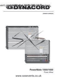
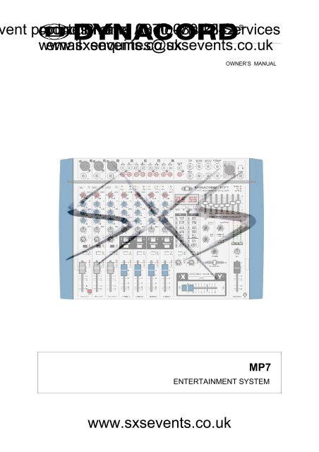
OWNER’S MANUAL<br />
<strong>MP7</strong><br />
ENTERTAINMENT SYSTEM<br />
www.sxsevents.co.uk
ent production courtesy Phone: of and Audio-Visual 0870 080 2342 Services<br />
www.sxsevents.co.uk<br />
email: enquiries@sxsevents.co.uk<br />
IMPORTANT SAFETY INSTRUCTIONS<br />
The lightning flash with arrowhead symbol, within an<br />
equilateral triangle is intended to alert the user to the<br />
presence of uninsulated “dangerous voltage” within the<br />
product’s enclosure that may be of sufficient magnitude to<br />
constitute a risk of electric shock to persons.<br />
The exclamation point within an equilateral triangle is<br />
intended to alert the user to the presence of important<br />
operating and maintance (servicing) instructions in the<br />
literature accompanying the appliance.<br />
1. Read these instructions.<br />
2. Keep these instructions.<br />
3. Heed all warnings.<br />
4. Follow all instructions.<br />
5. Do not use this apparatus near water.<br />
6. Clean only with a dry cloth.<br />
7. Do not block any of the ventilation openings.<br />
Install in accordance with the manufacturer’s instructions.<br />
8. Install only in rack with back cover.<br />
9. Only use attachments/accessories specified by the manufacturer.<br />
10. Refer all servicing to qualified service personnel. Servicing is required when the apparatus has been<br />
damaged in any way, such as power-supply cord or plug is damaged, liquid has been spilled or objects have fallen<br />
into the apparatus, the apparatus has been exposed to rain or moisture, does not operate normally, or has<br />
been dropped.<br />
11. To completely disconnect mains power from this apparatus, the power supply cord must be unplugged<br />
For US, CANADA and Japan only:<br />
Do not defeat the safety purpose of the grounding-type plug. A grounding type plug has two blades and a third grounding prong.<br />
The wide blade or the third prong are provided for your safety. When the provided plug does not fit into your outlet, consult an<br />
electrican for replacement of the obsolete outlet.<br />
IMPORTANT SERVICE INSTRUCTIONS<br />
CAUTION: These servicing instructions are for use by qualified personnel only. To reduce the risk of<br />
electric shock, do not perform any servicing other than that contained in the Operating<br />
Instructions unless you are qualified to do so. Refer all servicing to qualified service<br />
personnel.<br />
1. Security regulations as stated in the EN 60065 (VDE 0860) and the CSA E60065-00 have to be obeyed when<br />
servicing the appliance.<br />
2. Use of a mains separator transformer is mandatory during maintenance while the appliance is opened, needs to be<br />
operated and is connected to the mains<br />
3. Switch off the power before retrofitting any extensions, changing the mains voltage or the output voltage.<br />
4. The minimum distance between parts carrying mains voltage and any accessible metal piece (metal enclosure),<br />
respectively between the mains poles has to be 3 mm and needs to be minded at all times.<br />
The minimum distance between parts carrying mains voltage and any switches or breakers that are not connected<br />
to the mains (secondary parts) has to be 6 mm and needs to be minded at all times.<br />
5. Replacing special components that are marked in the circuit diagram using the security symbol (Note) is only permissible<br />
when using original parts.<br />
6. Altering the circuitry without prior consent or advice is not legitimate.<br />
7. Any work security regulations that are applicable at the location where the appliance is being serviced have to be strictly<br />
obeyed. This applies also to any regulations about the work place itself.<br />
8. All instructions concerning the handling of MOS - circuits have to be observed.<br />
Note:<br />
SAFETY COMPONENT (HAS TO BE REPLACED WITH ORIGINAL PART ONLY)<br />
www.sxsevents.co.uk<br />
22
Introduction. . . . . . . . . . . . . . . . . . . . . . . . . . . . . . . . . . . . . . . . 23<br />
Input/Mono . . . . . . . . . . . . . . . . . . . . . . . . . . . . . . . . . . . . . . . . 24<br />
Input/Stereo . . . . . . . . . . . . . . . . . . . . . . . . . . . . . . . . . . . . . . . 28<br />
Effect . . . . . . . . . . . . . . . . . . . . . . . . . . . . . . . . . . . . . . . . . . . . 31<br />
Transition/Phones. . . . . . . . . . . . . . . . . . . . . . . . . . . . . . . . . . . 33<br />
Master . . . . . . . . . . . . . . . . . . . . . . . . . . . . . . . . . . . . . . . . . . . 34<br />
Rear panel . . . . . . . . . . . . . . . . . . . . . . . . . . . . . . . . . . . . . . . . 37<br />
Standard installation . . . . . . . . . . . . . . . . . . . . . . . . . . . . . . . . 38<br />
Specifications . . . . . . . . . . . . . . . . . . . . . . . . . . . . . . . . . . . . . . 62<br />
Block diagram. . . . . . . . . . . . . . . . . . . . . . . . . . . . . . . . . . . . . . 63<br />
Dimensions. . . . . . . . . . . . . . . . . . . . . . . . . . . . . . . . . . . . . . . . 64<br />
Warranty. . . . . . . . . . . . . . . . . . . . . . . . . . . . . . . . . . . . . . . . . . 68<br />
DESCRIPTION<br />
ent production courtesy Phone: of and Audio-Visual 0870 080 2342 Services<br />
CONTENTS<br />
www.sxsevents.co.uk<br />
email: enquiries@sxsevents.co.uk<br />
Congratulations!<br />
You will find out that purchasing a <strong>MP7</strong> Entertainment System was an excellent decision.<br />
The design of the <strong>MP7</strong> is based on decades of experience, research and development as well as a steadfast<br />
manufacturer-customer-relationship in the professional audio market. With the <strong>MP7</strong> you own a power mixer that offers<br />
a wide range of functionality in a truly compact frame. All the troubling experience with cabling and matching mixers,<br />
amplifiers, FX-units and equalizers now belongs to history. The mixer’s ergonomic layout and clearly structured<br />
controls allow instant access at all times. The <strong>MP7</strong> additionally provides the possibility for connecting a litlite to<br />
compensate for poor lighting in a live mixing environment. Recessed carrying handles in both side panels and an<br />
extremely sturdy transport coverlid protecting the controls ensure easy and safe transportation. Besides, if you want<br />
to include your <strong>MP7</strong> in a 19" rack system, the only thing you have to do is to exchange the side panels for metal rack<br />
ears. Its powerful 2x300W/4ohms power amp, a huge amount of functions, high dynamic range, low-noise design<br />
and its 18-bit Dual-Stereo FX-section, the <strong>MP7</strong> is best equipped for universal use.<br />
The <strong>MP7</strong> is going to fulfill all your expectations that you can possibly demand of an Entertainment System.<br />
Use this owner’s manual as a guide when exploring the capabilities of your <strong>MP7</strong>. The vast amount of integrated<br />
functions is all explained systematically and point-by-point. Moreover, you will find some useful tips on how to<br />
overcome general difficulties during live-performance applications.<br />
Unpacking and Warranty<br />
Open the packaging and carefully take out the <strong>MP7</strong>. Detach the protective foil covering the FX-unit display. In addition<br />
to this owner’s manual you will find the mains cord and the warranty card. Please make sure that the warranty<br />
registration form is filled out correctly. You will be able to apply for warranty claims only when this form has been<br />
completed. We grant 36 months of warranty, starting with the date of the original purchase. Therefore we ask you to<br />
also keep the original certificate of purchase, stating the date of purchase. Experience has shown that keeping the<br />
original packing as well as carefully storing all documents accompanying the appliance generally increases the price<br />
when reselling the device.<br />
Installation and Connections<br />
Always install the <strong>MP7</strong> on an even surface to allow for sufficient airflow during operation. The device is equipped with<br />
an electronically controlled fan to protect the power amplifier section against thermal overload. The ventilation direction<br />
is Front-to-Rear. Fresh, cold air enters the mixer at its front side and warm air leaves the appliance through the<br />
ventilation louvers in the rear panel. Do not cover the frontal or the rear ventilation louvers, since otherwise, the <strong>MP7</strong><br />
would automatically enter protect mode, preventing damage through thermal overload. When protect mode is<br />
engaged, the device is not going to be damaged. Nevertheless, regular operation is not possible during this period<br />
of time. In case you have decided to install the <strong>MP7</strong> in a 19" rack system, make sure to leave at least 2RU of room<br />
above and at least 1RU of empty space below the appliance. Of course, you can cover the resulting gaps in the rack<br />
system using optionally available blinds with ventilation louvers. Before establishing the mains connection, please<br />
make sure that the appliance matches the voltage and frequency of your local mains supply. Mind the label next to<br />
the mains switch stating the operation voltage your <strong>MP7</strong> is factory-preset to. When switching the <strong>MP7</strong>’s power on,<br />
the internal fan will run for approximately 2 seconds at full speed. This is to provide you with an acoustic signal that<br />
the mixer is ready for operation. Additionally, any dust particles that might have gotten into the enclosure are blown<br />
out. The SPEAKER OUTPUTS on the rear panel of the <strong>MP7</strong> are provided through professional standard SPEAKON<br />
high-performance connectors, which offer absolute secure connection. The pin-assignment of these sockets is 1+<br />
(hot) and 1- (cold).<br />
www.sxsevents.co.uk<br />
23
INPUT/MONO<br />
ent production courtesy Phone: of and Audio-Visual 0870 080 2342 Services<br />
www.sxsevents.co.uk<br />
email: enquiries@sxsevents.co.uk<br />
1. MIC<br />
Electronically balanced XLR-type inputs (identical to the ones found on major studio and<br />
live sound mixing consoles) for connecting low-impedance microphones. The input stage<br />
provides extremely low noise and low hum signal processing at an outstandingly low<br />
distortion rate (
INPUT/MONO<br />
ent production courtesy Phone: of and Audio-Visual 0870 080 2342 Services<br />
www.sxsevents.co.uk<br />
email: enquiries@sxsevents.co.uk<br />
Another welcome side effect is, that the power amplifier and the connected loudspeaker<br />
systems are not “polluted” by low-frequency interference “closing off” the sound system,<br />
which certainly is not in yours or the audience’s interest. Your speaker systems will provide<br />
you with a truly clear, natural, and powerful sound performance when using the Lo CUT<br />
filter.<br />
4. GAIN<br />
Rotary control for adjusting the MIC or LINE inputs’ sensitivity, while optimally matching the<br />
incoming signals to the mixer’s internal operation level. Cautious adjusting offers the benefits<br />
of an improved S/N-ration and provides you with the full bandwidth of the <strong>MP7</strong>’s outstanding<br />
sound capabilities. On the XLR-type connectors an amplification of +10dB is achieved when<br />
the control is set all the way to the left and +60dB when the control is set to its maximum<br />
position to the right. Especially when dealing with very low input levels, like they occur during<br />
vocal recordings or when picking up distant sound sources, the high gain is extremely<br />
profitable. Using the LINE-input, the signal is generally attenuated by -20 dB, while<br />
maintaining the total adjustment range of 50dB. The LINE-input’s unity gain - no amplification<br />
(0 dB) - is achieved at the 20dB mark. The following is meant as a short note for your<br />
assistance on how to determine the correct input level.<br />
Note on how to set the input level:<br />
1. Set the gain control and the corresponding channel fader to their minimum setting.<br />
2. Connect the desired sound source (microphone, musical instrument, ...) to the<br />
corresponding MIC or LINE input.<br />
3. Play the sound source at its highest volume setting; respectively, sing or speak as<br />
loud as possible directly into the microphone.<br />
4. While doing so, adjust the input level using the gain control, so that during the loudest<br />
passages the PEAK LED is just not lit, but the SIGNAL-LED lights constantly.<br />
This is the basic channel setting, leaving you with at least 8dB of headroom. Which means,<br />
you have at least a range of 8dB before signal clipping. In case you intend to<br />
make further adjustments to the channel’s EQ setting, you should perform steps 3. and<br />
4. again afterwards, since changes in the sound shaping section also influence the<br />
channel’s overall level.<br />
5. EQ SECTION<br />
The mixer’s EQ section allows very differentiated shaping of the incoming audio signal within<br />
different frequency bands. Turning an EQ level control to the right enhances / amplifies the<br />
corresponding frequency range while turning it to the left lowers / attenuates the signal of<br />
that specific frequency band. Before altering to the sound, all EQ controls should be set to<br />
their neutral position; i.e. their markers point straight up (detent position). If possible, do not<br />
set the EQ controls to extreme positions. Usually, minor changes are totally sufficient and<br />
produce the best results in the overall sound. You should use a natural sounding<br />
reproduction as an orientation mark and rely on your musically trained ear, which still is one<br />
of the best instruments for judging the sound quality. Try to avoid excessive enhancement<br />
of the MID band. The moderate use of the MID control is the best remedy to avoid acoustical<br />
feedback. Lowering the frequency<br />
band’s level more or less will provide<br />
you with high amplification rates without<br />
feedback. Set the LO-EQ in accordance<br />
to your personal taste, for<br />
instance to achieve the desired, voluminous<br />
vocal sound. Use the HI-EQ to<br />
provide vocals with more crisp.<br />
www.sxsevents.co.uk<br />
27
INPUT/MONO<br />
ent production courtesy Phone: of and Audio-Visual 0870 080 2342 Services<br />
www.sxsevents.co.uk<br />
email: enquiries@sxsevents.co.uk<br />
6. PAN<br />
The setting of the PAN control defines the input signal’s position within the stereo image.<br />
When set to its center position, the audio signal is fed with equal levels to the left and right<br />
master busses. The PAN section’s design ensures that the overall relative level of an audio<br />
signal is maintained, no matter to what position within the stereo image the PAN control is<br />
set.<br />
7. FX1/2<br />
Using the FX1/2 control lets you route the corresponding input signal to the integrated digital<br />
effects units FX1 or FX2 at variable levels. In this way assigning special effects to musical<br />
instruments or vocals is fairly simple. When establishing an effect-mix, it is good advice to<br />
start with all FX-controls set to their center position. From this point you can increase or<br />
reduce the effect’s intensity, depending on your personal preferences. Please make sure<br />
to carefully monitor the PEAK LED’s in the FX1/2 channels during a performance. The<br />
indicator should only light briefly at the occurrence of peak signals. If the LED lights<br />
constantly, it is strongly recommended to lower the affected channels’ send levels at their<br />
FX1/2 controls. For further information, please refer also to the paragraphs on the FX1/2<br />
units.<br />
8. MUTE<br />
Engaging the MUTE button mutes the audio signal of the corresponding input channel.<br />
9. PFL<br />
Engaging this button assigns a channel’s audio signal to the PFL bus. For monitoring the<br />
PFL bus signal via headphones slide the PHONES MIX fader in the direction “PFL”.<br />
Simultaneously assigning more than one channel to the PFL bus is possible, while the<br />
individual channel’s volume fader setting is not recognized (PRE FADER LISTEN). Once<br />
a PFL button is pressed, the master display automatically enters PFL/PGM mode (yellow<br />
LED below the display lights). The right LED-chain indicates the level of the master audio<br />
signal (PGM), while the left LED-chain indicates the PFL bus signal level. This allows you<br />
setting a signal’s correct level or making special EQ-adjustments without the need of<br />
including it in the main mix.<br />
10. SIGNAL / PEAK indicator<br />
The Signal / Peak indicator provides optical information of a channel’s actual signal level<br />
at all times. As already mentioned in the chapter “setting instructions”, the “signal present”<br />
LED should blink in the rhythm of the incoming signal. If this is not the case, increasing the<br />
input level using the gain control is necessary. On the other hand, if the PEAK LED blinks<br />
frequently or lights constantly, the corresponding channel is likely to enter clipping and you<br />
have to reduce amplification using the gain control. The “signal present” LED lights at levels<br />
30dB below clipping while the peak LED lights at a level of 8dB below the occurrence of<br />
overdrive. To prevent the mixer’s input channels from clipping, which for instance may be<br />
caused by increasing volumes, keeping an eye on these indicators during operation is a<br />
good idea, too. Of course, engaging a channel’s PFL-button allows monitoring that channel’s<br />
level via the display in the master section. Be sure to only engage the PFL-key of the channel<br />
that you are about to adjust. The channel’s level is displayed in the master display’s left<br />
LED-chain. Here as well, make sure that the red LED (+12dB) lights only briefly during<br />
dynamic peaks.<br />
www.sxsevents.co.uk<br />
28
INPUT/MONO<br />
ent production courtesy Phone: of and Audio-Visual 0870 080 2342 Services<br />
www.sxsevents.co.uk<br />
email: enquiries@sxsevents.co.uk<br />
11. VOLUME<br />
The channel fader is used to set the volume of a single channel and to establish an accurately<br />
proportioned mix of all input signals. The channel faders should be positioned within the<br />
range of -5dB to 0dB, leaving you with a sufficient degree of control to allow precise matching<br />
of relative big differences in the channel’s level settings. Afterwards the overall volume is<br />
set through the use of the master fader. Even though the channel faders offer an additional<br />
gain of +10dB, it is good advice not to exceed the +5dB position.<br />
12. TALK<br />
The TALK-key is specially meant for announcements or DJ-like moderation with background<br />
music programs (talk over). Engaging this key automatically attenuates the signal levels of<br />
the channels 2-7 by about 15dB. Therefore the announcer channel (channel 1) clearly<br />
stands above the rest mix, without need to alter any of the mixer’s level settings. Since the<br />
TALK function is only active as long as the TALK-key is kept pressed down, you have to<br />
engage it for the entire period of time you want to make an announcement. As long as the<br />
TALK-key is not engaged, channel 1 functions like channels 2 and 3.<br />
www.sxsevents.co.uk<br />
29
INPUT/STEREO<br />
ent production courtesy Phone: of and Audio-Visual 0870 080 2342 Services<br />
www.sxsevents.co.uk<br />
email: enquiries@sxsevents.co.uk<br />
13. STEREO INPUT<br />
A (CD/MD):<br />
Unbalanced stereo inputs for connecting LINE level devices like for example: CD-Players,<br />
MD-Players, Tape Decks, PC <strong>Sound</strong>cards, etc.<br />
B (phono): only channels 4/5<br />
- stereo inputs with RIAA equalization for the connection of magnetic turntable pickups.<br />
Caution: Make sure to connect magnetic turntable pickup systems only. These inputs<br />
are not suitable for connecting high-level audio signal sources like CD-Players, etc.!<br />
Do not forget to connect the turntable’s ground wire to the PHONO GROUND binding<br />
post. Otherwise it is likely that you are faced with interference noise.<br />
Tip: When using turntables, high acoustic output levels can result in unwanted feedback.<br />
You can avoid this from happening during a performance by rehearsing the latter scenario.<br />
Set the sound system to the desired maximum output level while using a turntable as sound<br />
source. Feedback mostly generates in the low-frequency range, for that the RIAA-equalization<br />
of the phono inputs amplifies the signal by up to approx. +20dB. Therefore, it is good<br />
advice not to position turntables and mixer gear directly in front of the loudspeaker systems.<br />
Pieces of plastic foam or special shock absorbers may be a remedy. But when using them<br />
make sure not to cover any ventilation louvers of the equipment.<br />
14. INPUT SELECT<br />
Simultaneously connecting audio signal sources to both inputs (A and B) is possible. Using<br />
the INPUT SELECT switch lets you select whether you want to reproduce the signal of<br />
source A (CD/MD) or B (turntable for channels 4/5 or CD/MD for channels 6/7). Before<br />
connecting a sound source, make sure to set the corresponding input’s CHANNEL FADER<br />
(22) to its minimum position. This prevents the connected loudspeaker systems and the<br />
audience from being abused by nasty crackling noise.<br />
15. GAIN<br />
The setting of this control defines a channel’s input sensitivity. It is fairly simple to match<br />
the input level of different audio signal sources by individually adjusting the GAIN controls<br />
of each channel, so that the signal LED “SIG” is constantly lit while the peak LED “PK” lights<br />
briefly during peak levels only. GAIN adjustment should always be carried out with<br />
EQ-controls set to their center position. This leaves enough headroom for later EQ-adjustment<br />
without clipping. Using the PFL/PGM Split function of the master display lets you trim<br />
a channel’s input level setting more precisely. Engage a PFL button and the yellow PFL/PGM<br />
LED beneath the master display will light while the right LED-chain indicates the level of<br />
the momentarily running master signal (PGM) and the left LED-chain indicates the PFL-bus’<br />
level.<br />
Tip: The correct use of the PFL/PGM Split function during mixing facilitates the matching<br />
of different signal levels to a great extent. Presuming that during playback you have set the<br />
channel faders to their maximum position, pressing the PFL-button of the channel that you<br />
are about to adjust the level for, lets you monitor the different levels on the master display.<br />
The left LED-chain indicates the level of the PFL-channel while the right LED-chain displays<br />
the level of the momentarily played back audio signal. Using the GAIN-controls this allows<br />
optimally matching the two signal levels.<br />
www.sxsevents.co.uk<br />
30
INPUT/STEREO<br />
ent production courtesy Phone: of and Audio-Visual 0870 080 2342 Services<br />
www.sxsevents.co.uk<br />
email: enquiries@sxsevents.co.uk<br />
16. TONE CONTROL<br />
The mixer’s tone control section allows<br />
very differentiated and effective shaping<br />
of the incoming audio signal within<br />
miscellaneous frequency bands. Turning<br />
one of the tone controls to the right<br />
enhances/amplifies the corresponding<br />
frequency range while turning it to the<br />
left lowers/attenuates the signal of the<br />
specific frequency band. Before altering<br />
the sound, all tone controls should<br />
be set to their neutral position; i.e. their<br />
marker points straight up (detent position).<br />
Please, keep in mind that the<br />
stereo channel EQ’s are so called Kill-<br />
EQ’s. Up to turning them to their -6dB marking the tone controls behave analogue to their<br />
counterparts in the mono-channels. When turning the controls further, the “Kill”-function<br />
becomes active and nearly totally attenuates the corresponding frequency band. The<br />
“Kill”-function is meant to be used as special effect providing you with the opportunity to<br />
produce mixes that are as creative and entertaining as possible. In this way and when using<br />
the <strong>MP7</strong> for Karaoke, the MID-control lets you effectively mute the lead vocals of the original<br />
recording.<br />
17. BAL<br />
This control lets you determine the proportion between a stereo-channels left and right audio<br />
levels. During the playback of pre-recorded music leaving the BAL-control as close as<br />
possible to its center position is strongly recommended. Extreme settings for this control<br />
should be left for effect purposes only.<br />
TRANSITION SECTION<br />
The TRANSITION FADER in the master section allows conveniently cross-fading between<br />
two channels. Assigning each stereo channel to one of the two fader-sides “X” or “Y” is<br />
possible via corresponding switches.<br />
18. ASSIGN X/Y<br />
This switch allows assigning the corresponding channel’s audio signal to either side “X” or<br />
“Y” of the TRANSITION FADER. The two LED’s next to the switch indicate the ASSIGNstatus<br />
(blue = X, green = Y, off = TRANSITION inactive).<br />
19. TRANSITION<br />
This switch allows assigning the corresponding channel to the TRANSITION FADER.<br />
CAUTION: Whenever you want to listen to a channel’s audio signal via the master<br />
while the corresponding TRANSITION-switch is set to “on”, you have to raise the<br />
channel fader and slide the TRANSITION FADER to the side, which you have<br />
previously selected using the ASSIGN X/Y (18) switch.<br />
20. PFL<br />
Engaging this button assigns a channel’s audio signal to the PFL bus. For monitoring the<br />
PFL bus signal via headphones slide the PHONES MIX fader in the direction “PFL”.<br />
Simultaneously assigning more than one channel to the PFL bus is possible, while the<br />
individual channel’s volume fader setting is not recognized (PRE FADER LISTEN). This<br />
allows you setting a signal’s correct level or making special EQ-adjustments without the<br />
need of including it in the main mix. Once a PFL button is pressed, the master display<br />
automatically enters PFL/PGM mode (yellow LED below the display lights). The right<br />
LED-chain indicates the level of the master audio signal (PGM), while the left LED-chain<br />
indicates the PFL bus signal level.<br />
www.sxsevents.co.uk<br />
31
INPUT/STEREO<br />
ent production courtesy Phone: of and Audio-Visual 0870 080 2342 Services<br />
www.sxsevents.co.uk<br />
email: enquiries@sxsevents.co.uk<br />
21. SIGNAL / PEAK indicator<br />
The Signal / Peak indicator provides optical information of a channel’s actual signal level<br />
at all times. As already mentioned in the chapter “GAIN”, the “signal present” LED should<br />
blink in the rhythm of the incoming signal. If this is not the case, increasing the input level<br />
using the gain control is necessary. On the other hand, if the PEAK LED lights constantly,<br />
the corresponding channel is likely to enter clipping and you have to reduce amplification<br />
using the gain control. The “signal present” LED lights at levels 30dB below clipping while<br />
the peak LED lights at a level of 8dB below the occurrence of overdrive. To prevent the<br />
mixer’s input channels from clipping, which for instance may be caused by increasing<br />
volumes, keeping an eye on these indicators during operation is a good idea, too. Of course,<br />
engaging a channel’s PFL-button allows monitoring that channel’s level via the display in<br />
the master section. Be sure to only engage the PFL-key of the channel that you are about<br />
to adjust. The channel’s level is displayed in the master display’s left LED-chain. Here as<br />
well, make sure that the red LED (+12dB) lights only briefly during dynamic peaks.<br />
22. CHANNEL FADER<br />
Stereo Fader for setting the volume of a stereo channel.<br />
Different from the fader function of the MIC input channels, here, the audio signal is not<br />
amplified when a channel fader is set to its maximum position. To be sure to use the mixer’s<br />
entire dynamic capacity, set the CHANNEL FADER during playback to its maximum<br />
position.<br />
www.sxsevents.co.uk<br />
32
EFFECT 1/2<br />
ent production courtesy Phone: of and Audio-Visual 0870 080 2342 Services<br />
www.sxsevents.co.uk<br />
email: enquiries@sxsevents.co.uk<br />
FX1/FX2<br />
The <strong>MP7</strong> employs two completely independent 18-bit stereo effect units - FX1 and<br />
FX2. The setting of the mono input channels’ individual FX-controls determines the<br />
audio signal that is fed to these two units. Identically configured, each unit provides<br />
99 stereo program presets, which can be selected through the use of the UP/DOWN<br />
buttons. The 99 preset programs are sorted by algorithm and effect type into different<br />
groups, as indicated on a printed label. The programs within each preset group are<br />
sorted in ascending order where higher numbers provide the same FX type with<br />
increased intensity. The presets 1 - 20 offer high quality reverberation effects that<br />
are equally suited for being used during live performances, in the recording studio or<br />
in your home recording environment. The program numbers 21 - 40 provide mixed<br />
effect types of echo/reverb and chorus/reverb while the numbers 41 - 60 offer different<br />
delay effects. The last group from 61 - 99 provides different flanger, chorus, and<br />
doubling presets as well as special delay and reverb programs. During the initialization<br />
of the FX-units, when turning the <strong>MP7</strong>’s power on, the preset 05 (Large Hall 3<br />
Bright) is selected for the FX1 while the FX2 unit is set to preset 55 (Delay Mono<br />
250ms). These two effect programs are equally suitable for live performances and<br />
recording applications, plus that they are especially useful complementing each other<br />
when using both FX-units at the same time. For a more detailed description and for<br />
selecting or testing effect presets, please, also refer to the supplementary information<br />
form “EFFECT PRESETS”, which lists all preset names together with the corresponding<br />
program profiles, their individual characteristics, and a description of how and<br />
in which combination they are best used. Take your time to test all presets and select<br />
the ones that are best suited for your specific needs. Program number “0" is a Slap<br />
Back Echo effect, which is mainly meant for service and testing purposes. That is the<br />
reason why it is not included in the effects listing on the front panel.<br />
FX1/FX2<br />
1.......10 11.......20 21.......30 31.......40 41.......50 51.......60 61.......99<br />
REVERB<br />
HALLS<br />
REVERB<br />
PLATES<br />
ECHO<br />
REVERB<br />
CHORUS<br />
REVERB<br />
DELAY<br />
STEREO<br />
DELAY<br />
MONO<br />
SPECIAL<br />
PROGRAMS<br />
23. DISPLAY<br />
The display always indicates the actually selected program number for the corresponding<br />
FX-unit.<br />
24. UP/DOWN<br />
The UP/DOWN-keys let you step through the effect programs one by one in<br />
increasing or declining order. Keeping either one button pressed for a longer period<br />
of time allows scrolling the effect program numbers with increased tempo.<br />
25. FX ON<br />
Engaging this switch turns the power of the corresponding internal FX-unit on and<br />
the green LED lights. For intelligibility reasons switching the FX-units off during<br />
announcements is recommended.<br />
Pushing down the TALK-button while making an announcement from the MIC1-input<br />
channel automatically reduces the audio signal’s effects portion.<br />
www.sxsevents.co.uk<br />
33
EFFECT 1/2<br />
ent production courtesy Phone: of and Audio-Visual 0870 080 2342 Services<br />
www.sxsevents.co.uk<br />
email: enquiries@sxsevents.co.uk<br />
26. PEAK LED<br />
These indicators signal if the input stages of the internal FX-units are driven into<br />
clipping. To achieve an adequate S/N-ratio, please adjust the FX units’ input level as<br />
follows.<br />
Note on how to adjust the FX input signal:<br />
1. Establish a “dry” mix - without effect settings - according to the previous<br />
descriptions.<br />
2. Set the FX-return control (27) of the corresponding effect channel to its<br />
center position.<br />
3. Use the UP/DOWN-buttons to select the desired FX-program preset.<br />
4. Press the FX ON-switch.<br />
5. Play the sound source of the desired input channel and adjust the desired<br />
amount of the FX-signal, using the FX-controls of the input channel until the<br />
resulting effect mix meets your requirements. Repeat this procedure for all<br />
input channels that you would like to include in the effect mix.<br />
6. Please make sure that the PEAK LED only lights frequently at highly dynamic<br />
signal peaks.<br />
7. Now, using the FX-return controls lets you alter the percentage of the effect<br />
signal in the main mix.<br />
It is good advice to keep an eye on the peak indicators when operating your <strong>MP7</strong><br />
to be able to quickly interact when the signal levels exceed the normal range and<br />
enter clipping.<br />
27. EFFECT RETURN FX1 / FX2<br />
The setting of these stereo controls determines the amount of the effect signal getting<br />
added to the main mix.<br />
www.sxsevents.co.uk<br />
34
TRANSITION / PHONES<br />
ent production courtesy Phone: of and Audio-Visual 0870 080 2342 Services<br />
www.sxsevents.co.uk<br />
email: enquiries@sxsevents.co.uk<br />
28. X/Y LED<br />
These LED’s indicate whether an input channel has been<br />
assigned to either side of the TRANSITION FADER (29).<br />
When these LED’s are dimmed, the transition function has<br />
not been activated for either input channel and the TRANSI-<br />
TION FADER is inactive.<br />
29. ASSIGNABLE TRANSITION<br />
This assignable fader allows comfortably cross-fading between<br />
the audio signals of two selected input channels.<br />
Please refer to the paragraph TRANSITION SECTION in the<br />
chapter INPUT STEREO.<br />
30. PHONES<br />
This control lets you adjust the headphones’ volume.<br />
Caution: Depending on the type of headphones connected<br />
to the phones jack, the <strong>MP7</strong> is capable of producing<br />
very high output levels via the phones output. Therefore,<br />
make sure to turn the control all the way to the left<br />
(minimum setting) before connecting the headphones.<br />
Be aware of the fact that listening to loud sound pressure<br />
levels over a longer period of time leads to hearing-damage!<br />
31. PHONES MIX<br />
This fader lets you cross-fade the PFL (audio signal sum of<br />
all channels with engaged PFL-function) and PGM (the actual<br />
master signal) audio signals via headphones.<br />
The fader lets you pre-listen the function of the TRANSITION<br />
FADER via headphones.<br />
32. PHONES<br />
STEREO phones jack for the connection of headphones with<br />
an impedance of 32 - 600 ohms. Two phones connectors are<br />
available: one on the controls panel and one on the mixer’s<br />
front panel.<br />
33. LAMP<br />
XLR-socket for connecting a gooseneck litlite (12VDC / 2.4W<br />
max.). Please be sure to painstakingly mind the specifications<br />
on the power consumption and pin-assignment of the<br />
used lamp. Overload or short-circuit can result in serious<br />
damage or failure of the output. If possible, only use the<br />
gooseneck litlite (112700), which is available from the DY-<br />
NACORD accessory assortment. If in doubt, please consult<br />
your local dealer.<br />
www.sxsevents.co.uk<br />
35
MASTER<br />
ent production courtesy Phone: of and Audio-Visual 0870 080 2342 Services<br />
www.sxsevents.co.uk<br />
email: enquiries@sxsevents.co.uk<br />
34. MASTER B<br />
This control allows setting the output level of the MASTER B, which is a<br />
second universal stereo output carrying the stereo-sum audio signal identical<br />
to the MASTER A. It is extremely useful in accomplishing sound<br />
reinforcement in a neighboring room or monitoring purposes using a second<br />
power amplifier. For more details, please refer to the CONFIGURATION<br />
EXAMPLES.<br />
35. STEREO/MONO<br />
The MASTER B outputs carry a stereo signal if this switch is set to the<br />
STEREO position (not engaged).<br />
When set to MONO (engaged), the MASTER B outputs the sum of the left<br />
and right channels.<br />
36. PRE/POST<br />
Setting this switch to PRE (not engaged) lets you control the MASTER B<br />
level independent from the level of the MASTER A. When set to POST<br />
(engaged), the MASTER B signal is post the MASTER A fader. Changing<br />
the level of MASTER A also alters the MASTER B level.<br />
37. MONO OUT<br />
This control lets you set the output level of the MONO OUT connector (40).<br />
The MONO OUT outputs the summed audio signal of the left and right<br />
channels independent from the setting of the MASTER A Fader (pre fader).<br />
The MONO OUT is mostly used for connecting the monitor system or a<br />
light control desk.<br />
38. SUB OUT<br />
The SUB OUT represents an output that is especially implemented for<br />
connecting a subwoofer via an external power amplifier. The SUB OUT<br />
audio signal relates to the MASTER A fader’s setting (post fader). It employs<br />
an internal 12dB/oct, 100Hz low-pass filter. The SUB OUT control lets you<br />
set the proportion between subwoofer and general output levels of the<br />
system.<br />
CAUTION: In case you would like to connect an active subwoofer to<br />
the SUB OUT connector, make sure that it does not incorporate an<br />
integrated frequency crossover or if so, that it is deactivated! If this is<br />
not possible, you are left with the options of choosing the Mono OUT<br />
or MASTER B outputs to accomplish the task.<br />
The SUB OUT audio signal is output via the SUB OUT connector (41).<br />
39. RECORD SEND<br />
These RCA-type connectors carry the MASTER A pre-fader audio signal,<br />
which means that the setting of the master fader doesn’t affect the level of<br />
the audio signal that is present at the RECORD SEND connectors, which<br />
let you connect a CD/MD recorder or TAPE/DAT deck. The nominal level<br />
of -10dBV at this output is suitable for professional use as well as for home<br />
recording purposes.<br />
40. - 43. OUTPUT CONNECTORS<br />
Impedance-balanced outputs for the connection of external gear. The<br />
outputs are carried out as stereo phone-type jacks. Whenever possible use<br />
balanced cables. Balanced cabling is the best method for avoiding problems<br />
with interference and humming (see chapter: Configuration of a standard<br />
PA-system)<br />
44. POWER AMP INPUT<br />
Electronically balanced input of the internal power amplifier with signal-split<br />
function. Connecting a phone-type plug interrupts the signal path between<br />
MASTER A and internal power amp. You can now feed the internal power<br />
amplifier from the POWER AMP INPUT. The MASTER A audio signal is<br />
still output via the MASTER A OUTPUTS.<br />
www.sxsevents.co.uk<br />
36
MASTER<br />
ent production courtesy Phone: of and Audio-Visual 0870 080 2342 Services<br />
www.sxsevents.co.uk<br />
email: enquiries@sxsevents.co.uk<br />
45. STATUS INDICATORS<br />
These LED’s provide information about the actual operational status<br />
of the <strong>MP7</strong>’s internal power amplifiers.<br />
POWER ON lights whenever the <strong>MP7</strong>’s power is set to ON. If, after<br />
switching the <strong>MP7</strong> on, the LED does not light, the first thing to do is<br />
to make sure that the mains plug is plugged in correctly. If that is the<br />
case and the LED still stays dimmed, please contact your dealer.<br />
The LIMIT indicator signals that the <strong>MP7</strong>’s internal power amplifiers<br />
are actually operated at their limits. Frequent blinking of the LED is<br />
acceptable, since the amplifiers’ incorporated limiters prevent the<br />
occurrence of distortion. Continuous lighting indicates that degradation<br />
in the outputted sound is likely to happen. In that case, reducing<br />
the master level is recommended.<br />
The PROTECT indicator lights when one of the power amplifiers’<br />
extensive protection functions - against thermal overload, HF-induction,<br />
DC at the outputs, and SOAR-protection - is activated. When<br />
the <strong>MP7</strong> is in protect mode, the speaker outputs are muted and the<br />
inputs of the power amplifier are short-circuited to prevent the<br />
amplifiers from being damaged. In this case you should first check if<br />
the frontal and/or rear ventilation louvers are blocked. Another cause<br />
for the activation of the protect functions might be, that you have<br />
connected more than three 8ohms speaker systems per power<br />
output. Please also disconnect the SPEAKON connectors and check<br />
the speaker cables for short circuit. During the power-on operation,<br />
the PROTECT LED always lights for about two seconds. This is<br />
normal. It indicates that the <strong>MP7</strong>’s protection circuitry is operational.<br />
46. 7-BAND EQUALIZER<br />
The <strong>MP7</strong>’s integrated, switchable 7-Band Stereo Graphic Equalizer<br />
is located in the L/R master channel section. The seven frequency<br />
bands - each providing ±10dB amplification/attenuation - offer the<br />
possibility to optimally match the overall sound to the acoustic<br />
conditions of different locations or shape it according to your personal<br />
taste.<br />
www.sxsevents.co.uk<br />
37
MASTER<br />
ent production courtesy Phone: of and Audio-Visual 0870 080 2342 Services<br />
www.sxsevents.co.uk<br />
email: enquiries@sxsevents.co.uk<br />
The frequency ranges as well as the characteristics of the EQ-faders<br />
are designed to meet your day-in-day-out requirements. In case you<br />
intend to have a clear and highly intelligible sound, you might want<br />
to increase the level setting of the 8kHz or 16kHz band a bit. If the<br />
mid-range sounds a bit nasal, try attenuating the mid-band by some<br />
decibels. If you like to provide your sound with more bass, you have<br />
to boost the low frequency range, using the 80Hz or the 250Hz<br />
controls. On the other hand, if the overall sound is undefined with<br />
too much bass, lowering the levels of these two frequency bands<br />
will solve the problem. Especially when using the equalizer, being<br />
aware of the fact that in most cases less can be more is good advice.<br />
47. EQ ON/OFF<br />
This switch activates or deactivates (ON / OFF) the integrated<br />
7-BAND-EQUALIZER.<br />
48. MASTER DISPLAY<br />
The MASTER DISPLAY offers two modes. The PFL/PGM LED (49)<br />
indicates which one is actually selected:<br />
a) MASTER A Level: LED (49) is dimmed. The two LED-chains<br />
indicate the audio level that is output via the MASTER A<br />
OUTPUTS L and R in dBu.<br />
b) PFL/PGM Split: LED (49) lights. This mode is automatically<br />
activated when pressing a PFL-button. The left LED-chain<br />
indicates the PFL-bus level while the right LED-chain indicates<br />
the audio level of the master sum. (please also refer to the<br />
chapter INPUT STEREO)<br />
49. PFL/PGM SPLIT LED<br />
Indicates the master display mode.<br />
50. BAL<br />
This control is for determine the ration of the levels of the left and<br />
right MASTER A output channels. During music playback, it is<br />
recommended to leave the BAL-control at its center position whenever<br />
possible. In most cases, extreme settings are only useful for<br />
effect purposes.<br />
51. MASTER A FADER<br />
Stereo fader for adjusting the overall volume as well as the output<br />
level of the internal power amplifiers and the MASTER A OUTPUTS.<br />
Please, make sure to close the fader of the corresponding input<br />
channel or at least the MASTER controls before connecting any<br />
audio signal sources. This will save yourself, your audience, and<br />
your equipment from unnecessary stress resulting from plug-in<br />
noise.<br />
www.sxsevents.co.uk<br />
38
REAR PANEL<br />
ent production courtesy Phone: of and Audio-Visual 0870 080 2342 Services<br />
www.sxsevents.co.uk<br />
SPEAKER OUTPUTS RIGHT / LEFT<br />
email: enquiries@sxsevents.co.uk<br />
The <strong>MP7</strong> provides professional SPEAKON-type high-performance<br />
connectors, which offer mechanically and electric secure<br />
connection that complies with any safety standards.<br />
Additionally, SPEAKON-type connectors allow utilizing highperformance<br />
loudspeaker cables with diameters of up to 4 x<br />
2.5mm 2 .<br />
Single plugs and jacks as well as high-performance speaker<br />
cables are available from the DYNACORD accessory assortment.<br />
POWER<br />
Mains switch for switching the <strong>MP7</strong>’s power ON or OFF. The<br />
appliance is operational when the POWER ON-LED lights and<br />
the power relays have switched the power amplifier output<br />
signal to the speaker outputs.<br />
Before switching the mixer’s power on, make sure to set<br />
the master faders to their minimum position. This will save<br />
yourself, your audience, and your equipment from unnecessary<br />
stress resulting from switching or feedback noise.<br />
When switching your audio system on with additional power<br />
amplifiers or other electronic equipment, like for example<br />
CD-Players, MD-Recorders, etc. connected, please proceed<br />
in the following sequence:<br />
1. switch the CD-Player’s power on<br />
2. switch the <strong>MP7</strong>’s power on<br />
3. switch the additionally connected gear (power<br />
amps) on<br />
Please proceed in the opposite sequence when switching the<br />
audio system off.<br />
PHONO GROUND<br />
Facility for connecting the chassis ground of a turntable. Make<br />
sure to connect the chassis ground to the PHONO GROUND<br />
screw. Otherwise you might be facing hum and interference<br />
noise.<br />
www.sxsevents.co.uk<br />
39
STANDARD INSTALLATION<br />
ent production courtesy Phone: of and Audio-Visual 0870 080 2342 Services<br />
www.sxsevents.co.uk<br />
email: enquiries@sxsevents.co.uk<br />
CABLING<br />
The mains cord is supplied with your <strong>MP7</strong>. The quality of all other cables is left to your responsibility. Carefully chosen<br />
high quality cables are the best precaution to prevent problems from occurring during the later operation. In the<br />
following we would like to provide you with some recommendations for the trouble-free operation of your setup.<br />
SPEAKER CABLES<br />
Our experience as a manufacturer of loudspeaker systems has taught us that flexible cables with a rubber jacket and<br />
a diameter of 2.5mm 2 per conductor, used in combination with SPEAKON plugs and sockets, are the best choice to<br />
guarantee the optimal connection of loudspeaker systems. The connection of the SPEAKON plugs to the<br />
corresponding connectors on the <strong>MP7</strong>’s rear panel has to be in accordance to the corresponding diagram below. We<br />
recommend the use 4-wire cables where also the pins 2+ and 2- are connected through. This provides you with the<br />
possibility to use these cables in an active 2-way system configuration, as well. DYNACORD speaker cables with<br />
SPEAKON connectors and all other cables, plugs, and sockets are available at your professional audio dealer.<br />
LF-CABLES – BALANCED OR UNBALANCED?<br />
For LF-cabling – all the low current wiring – your best choice are balanced cables (2 signal conductors + ground<br />
shielding) with XLR-type connectors or stereo phone jacks and plugs. The cables should be step proof, shielded,<br />
and never longer than absolutely necessary. Too many too long cables mostly lead to confusion and generate<br />
unnecessary problems.<br />
Of course, you can also connect unbalanced cables with monaural phone plugs to the <strong>MP7</strong>’s in- and outputs and<br />
because of its superb grounding managing system, in most cases no interference will occur. Still, there is a minimal<br />
risk that problems could arise. Generally spoken, if you have the choice, balanced LF-cables are always the better<br />
solution and they should be preferred. Today’s modern audio equipment – like amplifiers, equalizers, FX units, mixing<br />
consoles, and even some keyboards – offers balanced in- and outputs. In a balanced signal path, the cable screen<br />
provides a gapless connection of all metal parts, offering efficient shielding against the induction of external noise.<br />
The balanced cabling in conjunction with the common-mode rejection of the <strong>MP7</strong>’s input stage effectively eliminates<br />
even existing artifacts of interference. All inputs of the <strong>MP7</strong> provide balanced audio connections and high<br />
common-mode rejection. The mixing stage outputs – MASTER B, MOMO OUT, etc. – are laid out in GND-SENSING<br />
technology – a special, impedance-balanced pin assignment of the output jacks, offering all advantages of the<br />
balanced signal transmission, but lets you also connect monaural phone plugs, without a problem. Nevertheless –<br />
as mentioned above – when longer cables are involved, using stereo phone plugs and balanced cables are the better<br />
alternative. The diagrams below show the pin assignments of plugs and cables like they can be used with the <strong>MP7</strong>.<br />
MIC INPUT of the <strong>MP7</strong><br />
balanced connection<br />
of microphones<br />
unbalanced<br />
All phone jack-type<br />
in/outputs of the <strong>MP7</strong><br />
external equipment<br />
with XLR-connectors<br />
for in- and output<br />
balanced<br />
unbalanced<br />
All phone jack-type<br />
in/outputs of the <strong>MP7</strong><br />
external equipment with<br />
jack-type connector for<br />
inputs and outputs<br />
balanced<br />
www.sxsevents.co.uk<br />
40
In the following we will explain how to set up a standard PA-system with monitoring facility using the <strong>MP7</strong>.<br />
The equipment list includes:<br />
1 <strong>MP7</strong><br />
2 Hi-range speaker system cabinets, e.g. CP 12-2<br />
2 Bass speaker system cabinets e.g. CP 12-1<br />
2 Loudspeaker pole-mount stands or 2 intermediate poles<br />
2 Speakon cables, 8m<br />
2 Speakon cables, 2m<br />
1 AM12 active monitor system<br />
1 LF-cable with stereo phone plugs<br />
STANDARD INSTALLATION<br />
ent production courtesy Phone: of and Audio-Visual 0870 080 2342 Services<br />
www.sxsevents.co.uk<br />
email: enquiries@sxsevents.co.uk<br />
Setting up<br />
— Look for the most suitable location to set up the loudspeaker systems. Whenever possible, place the bass<br />
cabinets on the floor and the Hi-range cabinets directly on top. However, in doing so, make sure that the<br />
hi-range cabinets’ lower edge is in the same height of the audience’s heads or above. You can either use<br />
intermediate poles between the bass and Hi-range cabinets or, if this does not provide enough elevation for<br />
the speaker systems or there are no bass cabinets included, use appropriate speaker pole-mount stands.<br />
— Compact overall sound is achieved by placing the left and right loudspeakers as far apart from each other as<br />
necessary but as close together as possible.<br />
— Make sure that the main speakers are not behind you. Otherwise you will be facing feedback whenever your<br />
system set-up includes microphones or turntables.<br />
— Use SPEAKON-type cables to establish connections between the loudspeaker systems and the <strong>MP7</strong>. Follow<br />
the instructions as shown in figure1. Make sure not to inadvertently reverse connect the left and right channels.<br />
The short SPEAKON-type cables are used to parallel connect Hi-range and Bass cabinets.<br />
(Fig. 1)<br />
www.sxsevents.co.uk<br />
41
STANDARD INSTALLATION<br />
ent production courtesy Phone: of and Audio-Visual 0870 080 2342 Services<br />
www.sxsevents.co.uk<br />
email: enquiries@sxsevents.co.uk<br />
— Place the needed sound source devices (e.g. CD-Player, turntable) or microphones on a secure even location<br />
and, if necessary, establish mains connections<br />
— Connect all the gear to the <strong>MP7</strong> (Fig. 2).<br />
(Fig. 2)<br />
— Employ cables with stereo phone-type plugs to connect the AM12 to the MONO OUT of the <strong>MP7</strong>. Set the<br />
LINE IN-control on the AM12 at its center position. This lets you control the AM12’s volume setting from the<br />
MONO OUT-control on the <strong>MP7</strong>.<br />
— Set all faders on the <strong>MP7</strong> at their minimum position and turn all output controls (e.g. MONO OUT)<br />
counterclockwise as far as possible. Switch on the power of all included components in the following sequence:<br />
1. <strong>Sound</strong> source equipment, e.g. CD-Player, turntable, etc.<br />
2. <strong>MP7</strong><br />
3. AM12 active monitors<br />
Following this order when switching on your system prevents unpleasant power-on noise and feedback.<br />
— Your PA-system is now ready for operation!<br />
www.sxsevents.co.uk<br />
42
1. A red LED next to the meter instruments that is constantly lit signals that the corresponding channel is on the<br />
verge of clipping! Use the Gain-control of the corresponding channel to reduce the audio signal level until the<br />
red LED lights only during program peaks.<br />
2. Avoid extreme output levels. The <strong>MP7</strong> is no “HiFi-toy”!<br />
Employing high-quality, high-performance PA-speaker systems, like the CP12-1 and CP12-2, allows sound<br />
reproduction at extreme high sound pressure levels, which bares the risk of resulting hearing damage. The<br />
same is true for the headphones output. Do not expose your ears to high sound pressure levels over an<br />
extended period of time. The use of closed DJ-type headphones provides improved shielding against outer<br />
noise and is therefore strongly recommended. Using these types of headphones automatically leads to reducing<br />
the sound level settings.<br />
3. The Master-EQ is primarily aimed for making minor corrections in the overall sound only. Employing high-quality<br />
loudspeaker systems is the best guarantee for a perfect sound, even with the Master-EQ being deactivated.<br />
4. Make sure to carefully test all components of the entire system prior to a live-performance. Test the system<br />
set to the output level, which you are going to use during the later performance.<br />
This is the only way to ensure that you are not facing feedback or other problems with the connected gear<br />
resulting from vibration, shock or other sources during the later performance.<br />
5. However, it is good advice to check the system’s overall sound quality as well as the volume setting during a<br />
performance and make corrections, if necessary.<br />
Example 1: Extending your system with an add-on subwoofer for more bass pressure is displayed in fig. 1.<br />
Ask your local dealer before extending your system!<br />
STANDARD INSTALLATION<br />
ent production courtesy Phone: of and Audio-Visual 0870 080 2342 Services<br />
When operating the <strong>MP7</strong> be sure to mind the following notes:<br />
www.sxsevents.co.uk<br />
email: enquiries@sxsevents.co.uk<br />
Example 2: In Fig. 3 you can see how to control larger PA-Systems with your <strong>MP7</strong>. Simply connect the MASTER A<br />
outputs with the external system amplifier and the MASTER B outputs with the POWER AMP INPUTS of the <strong>MP7</strong>.<br />
The volume of the Main-PA is controlled by the master fader, like before. MASTER B drives the internal amplifiers<br />
and provides a full-stereo monitoring via two additional monitor cabinets.<br />
(Fig. 3)<br />
www.sxsevents.co.uk<br />
43
SPECIFICATIONS<br />
ent production courtesy Phone: of and Audio-Visual 0870 080 2342 Services<br />
www.sxsevents.co.uk<br />
email: enquiries@sxsevents.co.uk<br />
Technical Specifications <strong>MP7</strong> Mixing desk in rated condition. Unity Gain (MIC Gain 20 dB), all faders position 0 dB, all pots in<br />
mid position, master fader + 6dB, amplifier rated output power into 8 ohms, one channel driven, unless otherwise specified.<br />
Maximum Midband Output Power, 1 kHz, THD = 1 %<br />
into 4 ohms<br />
2 x 340 W<br />
into 8 ohms<br />
2 x 200 W<br />
Rated Output Power, 20Hz… 20 kHz, THD =0.2%<br />
into 4 ohms<br />
2 x 300 W<br />
into 8 ohms<br />
2 x 150 W<br />
Maximum Output Voltage of the power amplifier, no load<br />
43 Vrms<br />
THD @ 1 kHz, MBW=80kHz<br />
MIC input to Main L/R output, +16 dBu < 0.006%<br />
Power amplifier input to speaker L/R output < 0.08%<br />
DIM 30, power amplifier < 0.03%<br />
IMD-SMPTE, power amplifier, 60Hz, 7 kHz < 0.2%<br />
Frequency Response, -3dB ref. 1 kHz<br />
Any input to any mixer output<br />
15Hz… 60kHz<br />
Any input to speaker output L/R<br />
30Hz... 40kHz<br />
Crosstalk, 1 kHz<br />
Fader attenuation<br />
> 90 dB<br />
Channel seperation<br />
> 70 dB<br />
Input Sensitivity, all level controls in max. position<br />
MIC input<br />
-74 dBu (155µV)<br />
Line Input (Mono)<br />
-54 dBu (1.55 mV)<br />
CD/MD Line Input (Stereo)<br />
-24 dBu (49 mV)<br />
Phone Input (Stereo)<br />
-61.5 dBu (652 µV)<br />
Power Amplifier Input +6 dBu (1.55 V)<br />
Maximum Level, mixing desk<br />
MIC inputs<br />
+11 dBu<br />
Line inputs<br />
+30 dBu<br />
All other inputs<br />
+20 dBu<br />
Record Send output<br />
+14 dBu<br />
All other outputs<br />
+20 dBu<br />
Input Impedances<br />
MIC<br />
1.8 kohms<br />
All other inputs<br />
> 10 kohms<br />
Output Impedances<br />
Record Send<br />
1 kohms<br />
Phones<br />
47 ohms<br />
All other outputs<br />
75 ohms<br />
Equivalent Input Noise, MIC Input, A-weighted 150 ohms<br />
-130 dBu<br />
Noise, Channel inputs to Main L/R outputs, A-weighted<br />
Master fader down<br />
-104 dBu<br />
Master fader 0 dB, Channel fader down<br />
-91 dBu<br />
Master fader 0 dB, Channel fader 0 dB, Channel gain unity<br />
-84 dBu<br />
Signal/Noise-Ratio, power amplifier, A-weighted<br />
105 dB<br />
Equalization STEREO<br />
LO Shelving<br />
+9/-30 dB / 60 Hz<br />
MID Peaking<br />
+9/-30 dB / 2.4 kHz<br />
HI Shelving<br />
+9/-30 dB / 12 kHz<br />
Equalization MIC<br />
LO Shelving<br />
±15 dB / 60 Hz<br />
MID Peaking<br />
±12 dB / 2.4 kHz<br />
HI Shelving<br />
±15 dB / 12 kHz<br />
Master EQ, 2x7-band, Stereo<br />
±10 dB<br />
Phantom Power, all MIC Inputs<br />
+24V dc<br />
Lamp<br />
+12V dc<br />
Power Requirements, factory preset, 50Hz....60Hz<br />
100V/120V/230V/240V<br />
Power Consumption at 1/8 maximum output power 4 ohms<br />
450 W<br />
Dimensions, (WxHxD), mm 455,5 x 175,8 x 340.6<br />
Weight, including lid<br />
13 kg<br />
Optional Rack-Mount-Kit <strong>MP7</strong> (NRS 90259) 112 844<br />
Wall-Mount-Kit <strong>MP7</strong> (NRS 90242) 112 742<br />
www.sxsevents.co.uk<br />
Transition Fader <strong>MP7</strong> (NRS 90261) 112 853
BLOCK DIAGRAM<br />
ent production courtesy Phone: of and Audio-Visual 0870 080 2342 Services<br />
www.sxsevents.co.uk<br />
email: enquiries@sxsevents.co.uk<br />
www.sxsevents.co.uk<br />
65
ABMESSUNGEN / DIMENSIONS<br />
ent production courtesy Phone: of and Audio-Visual 0870 080 2342 Services<br />
www.sxsevents.co.uk<br />
Abmessungen/Dimensions email: enquiries@sxsevents.co.uk<br />
(in mm)<br />
www.sxsevents.co.uk<br />
66
ent production courtesy Phone: of and Audio-Visual 0870 080 2342 Services<br />
GARANTIE<br />
WARRANTY<br />
GARANTIE<br />
www.sxsevents.co.uk<br />
email: enquiries@sxsevents.co.uk<br />
Das Werk leistet Garantie für alle<br />
nachweisbaren Material- und Fertigungsfehler<br />
für die Dauer von 36<br />
Monaten ab Verkauf.<br />
Garantieleistungen werden nur<br />
dann anerkannt, wenn gültige, d.h.<br />
vollständig ausgefüllte Garantieunterlagen<br />
vorliegen.<br />
Von der Garantie ausgenommen<br />
sind alle Schäden, die durch falsche<br />
oder unsachgemäße Bedienung<br />
verursacht werden. Bei Fremdeingriffen<br />
oder eigenmächtigen Änderungen<br />
erlischt jeder Garantieanspruch.<br />
The manufacturer’s warranty covers<br />
all substantial defects in materials<br />
and workmanship for a period<br />
of 36 months from the date of<br />
purchase.<br />
Liability claims are accepted solely,<br />
when a valid – correctly and completely<br />
filled out – Warranty Registration<br />
form is presented by the original<br />
owner of the product. The warranty<br />
does not cover damage that results<br />
from improper or inadequate treatment<br />
or maintenance. In case of<br />
alteration or unauthorized repairs,<br />
the warranty is automatically terminated.<br />
La garantie constructeur couvre<br />
tous les défauts matériels et de<br />
main d’œuvre pour une période de<br />
36 mois à compter de la date<br />
d’achat. La garantie ne sera reconnue<br />
que si la Carte de Garantie,<br />
correctement et complètement remplie,<br />
est présentée par l’acheteur<br />
d’origine du produit. Les dommages<br />
dus à un mauvais maniement de<br />
l’appareil, à un traitement ou une<br />
maintenance incorrects ou inadéquats<br />
ne sont pas garantis. Toute<br />
modification ou intervention effectuée<br />
par une personne non qualifiée<br />
entraîne la résiliation automatique<br />
de la garantie.<br />
GmbH • Hirschberger Ring 45 • 94315 Straubing •Telefon (09421) 706-0 •Telefax (09421) 706-265<br />
Änderungen vorbehalten. Subject to change without prior notice. Printed in Germany 14. 06. 2001 / 360468<br />
www.sxsevents.co.uk<br />
Internet: http:// www.dynacord.de