

Line Isolation Monitor (LIM) LIM2000plus® - Bender
Line Isolation Monitor (LIM) LIM2000plus® - Bender
Line Isolation Monitor (LIM) LIM2000plus® - Bender

You also want an ePaper? Increase the reach of your titles
YUMPU automatically turns print PDFs into web optimized ePapers that Google loves.
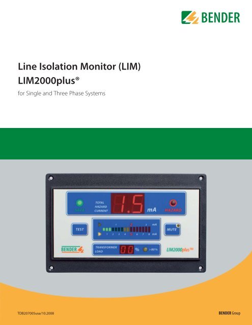
<strong>Line</strong> <strong>Isolation</strong> <strong>Monitor</strong> (<strong>LIM</strong>)<br />
<strong>LIM</strong>2000plus®<br />
for Single and Three Phase Systems<br />
TDB207005usa/10.2008<br />
BENDER Group
<strong>Line</strong> <strong>Isolation</strong> <strong>Monitor</strong><br />
<strong>LIM</strong>2000plus®<br />
for Single and Three Phase Systems<br />
<strong>LIM</strong>2000plus®<br />
Device features<br />
• No interference with electrical equipment<br />
• Special phase-locking circuitry<br />
for ultimate stability and repeatability<br />
• Voltage-free SPDT contact for external<br />
alarm<br />
• Provision for Remote Indicators<br />
• Internal overload protection with<br />
automatic reset<br />
• Easy to clean rugged Lexan front foil<br />
• Digital & Analog Bar Graph Displays<br />
• Automatic self-calibration and self-check<br />
• Audible alarm volume adjustable via<br />
menu<br />
• Transformer Load <strong>Monitor</strong>ing<br />
• RS-485 communication port<br />
Product Description<br />
The <strong>Line</strong> <strong>Isolation</strong> <strong>Monitor</strong> (<strong>LIM</strong>) measures the total leakage impedance to ground in an<br />
isolated (ungrounded) AC power system. Based on this information, the maximum Total<br />
Hazard Current (THC) is determined and displayed on a seven-segment display and LED<br />
bar graph display.<br />
The <strong>LIM</strong> is available for operation in 50 or 60 Hz systems with AC voltages from 100 to<br />
240 V. The supply voltage for the <strong>LIM</strong> is taken from the system being monitored.<br />
For additional safety, two separate ground connections are provided. Each ground must<br />
be wired individually to the Reference Grounding Bus. A break in either connection will<br />
cause the <strong>LIM</strong> to alarm.<br />
<strong>Monitor</strong>ing the transformer load current is a desirable feature in modern operating room<br />
(OR) and intensive care units as more and more medical electrical (ME) equipment is<br />
being supplied with isolated power. A flashing yellow indicator LED warns the staff when<br />
the transformer has reached 80% capacity. At 100 % transformer capacity the indicator<br />
LED is solidly on and an audible alarm sounds as well.<br />
The <strong>LIM</strong>2000plus® is ideal for retrofit applications regardless of the make or type of the<br />
existing product. No metal needs to be cut and simple instructions will generally facilitate a<br />
changeover in less than one hour.<br />
Operational Information<br />
Usually, the impedance between each isolated conductor and ground is different, resulting<br />
in a different current flowing through a person making physical contact between any one<br />
of the isolated conductors and ground. The <strong>LIM</strong> calculates and displays the true maximum<br />
value of the Total Hazard Current (THC). The BENDER <strong>LIM</strong> performs this function using a<br />
patented measurement technique.<br />
The THC is shown on the seven-segment display and the LED bar graph. Normally, the green<br />
“SAFE” LED is illuminated, the display shows a low leakage value and the bar graph is in<br />
the non-alarm, or safe, green zone. THC levels will increase as additional loads are connected<br />
to the system and/or when a line-to-ground fault has suddenly occurred or is slowly developing.<br />
A visual and audible alarm is generated when the THC exceeds the <strong>LIM</strong> setting of<br />
either 2 mA or 5 mA. Relay output contacts are available, which can be wired into a circuit<br />
to trigger an external alarm.<br />
The red “HAZARD” LED remains illuminated for the duration of the fault. The audible alarm<br />
can, however, be silenced by pushing the “MUTE” button at the discretion of personnel<br />
near the <strong>LIM</strong>. When the “MUTE” button is activated, the built-in amber LED in the “MUTE”<br />
button is illuminated to indicate a muted condition. After the fault is removed, the <strong>LIM</strong> will<br />
automatically reset to safe condition indications.<br />
Activate the test button to check the <strong>LIM</strong> operation. Making this test does not add to the hazard<br />
current of a system in actual use, nor does the test include the effect of the line-to-ground<br />
stray impedance of the system.<br />
The <strong>LIM</strong> has provisions to connect one or more remote indicators, with or without digital<br />
meter. The remote indicators duplicates the audible and visible alarm signals of the <strong>LIM</strong>.<br />
The audible alarm volume level is adjustable via the configuration menu.<br />
Standards<br />
The BENDER <strong>LIM</strong>2000plus® Series <strong>LIM</strong> complies with UL 1022 in the U.S. and CSA-C22.2<br />
No. 204-M1984 in Canada. The intent is to include the <strong>LIM</strong> as part of an isolated power<br />
system that conforms with the applicable requirements of ANSI/NFPA 99 and ANSI/NFPA<br />
70 in the U.S. and in accordance with CAN/CSA-C22.2 No. 29-M1989 in Canada.<br />
Safety Instructions<br />
WARNING<br />
Only qualified personnel, in consideration of the applicable safety regulations,<br />
shall install electrical equipment!<br />
2 TDB207005usa/ 10.2008
<strong>Line</strong> <strong>Isolation</strong> <strong>Monitor</strong> <strong>LIM</strong>2000plus®<br />
Display <strong>LIM</strong>2000plus®<br />
3 4 5 6<br />
2 1 9 8 7<br />
1 - THC Set Point LED Markers (amber) – Either 5 mA (U.S.)<br />
or 2 mA (Canada)<br />
2 - “TEST” Button – Checks functions of the <strong>LIM</strong><br />
3 - “SAFE” LED (green) – Lit unless <strong>LIM</strong> is in alarm mode<br />
4 - Digital Display – Displays THC in mA<br />
5 - Analog LED Bar Graph – Displays THC in mA<br />
6 - “HAZARD” LED (red) – Dark unless THC > Set Point<br />
7 - “MUTE” Button w/built-in LED (amber) – Silences alarm buzzer<br />
8 - “> 80%” LED (amber) – Flashes at 80%, solid on at 100% transformer<br />
load<br />
9 - Digital Display “%” – Indicates % of rated transformer load<br />
Ordering Details<br />
<strong>LIM</strong><br />
Product Type Description Approval Article No.<br />
<strong>LIM</strong>2000-1CB 100 – 120 V / 1-Phase 92075002<br />
<strong>LIM</strong>2000-1CB 200 – 240 V / 1-Phase 92075004<br />
<strong>LIM</strong>2000-3CB 200 – 240 V / 3-Phase 92075005<br />
Remote Indicator<br />
Product Type Description Approval Article No.<br />
MK2000-G1 Mute 923520<br />
MK2000-G2 Mute 923521<br />
MK2000P-G1 Mute + Test 923523<br />
MK2000C-G1 Mute + Overload 923522<br />
MK2000M-G2 Mute + Overload -- 923540<br />
MK2000CP-G1 Mute + Test + Overload 923529<br />
MK2000CBM-G2 Mute + Test + Digital Metering<br />
+ Overload<br />
-- 923545<br />
Connector Plate<br />
Product Type Description Approval Article No.<br />
CP-<strong>LIM</strong>2000 <strong>LIM</strong> and remote connections 92075100<br />
CP-<strong>LIM</strong>2000CB <strong>LIM</strong>, CT, and digital remote 92075007<br />
Current Transformer (CT)<br />
Product Type Description Approval Article No.<br />
STW3 Up to 100 A load current 98021000<br />
STW4 Over 100 A load current 98021001<br />
Error Code Listing<br />
ER 1.0 <strong>LIM</strong>-GND or GND2 connection interrupted<br />
ER 2.0 A/D converter calibration failed; hardware malfunction<br />
ER 3.0 Measuring circuit test failure; hardware malfunction<br />
ER 4.0 Actual system voltage is above <strong>LIM</strong> calibrated voltage<br />
ER 4.5 Actual signal voltage is above <strong>LIM</strong> calibrated voltage<br />
ER 5.0 <strong>LIM</strong> hardware malfunction<br />
ER 6.0 Program sequence interrupted; EMI interference<br />
ER 6.5 Program sequence interrupted; stack point indication too<br />
high<br />
ER ER Error in the current measuring circuitry<br />
The error code is displayed on the seven-segment digital display<br />
(4). The display alternates between “ER” and the applicable numeric<br />
code, i.e. “ER” and “4.5”. The only exception is when the error code<br />
is “ER”. In this case, “ER” appears continiously in the display.<br />
TDB207005usa/ 10.2008 3
<strong>Line</strong> <strong>Isolation</strong> <strong>Monitor</strong> <strong>LIM</strong>2000plus®<br />
Standard Connector Plate Wiring Diagram<br />
3<br />
1<br />
2<br />
5<br />
7<br />
8<br />
4<br />
6<br />
1 - To <strong>LIM</strong>2000plus (Connector viewed from mating end)<br />
L1, L2 To secondary of <strong>Isolation</strong> Transformer.<br />
12 V DC Com. Common connection<br />
M-, M+<br />
External mA meter (400 μA)<br />
RI1<br />
Test button source<br />
K1/NC<br />
NC contact of the alarm relay K1<br />
K1/Common Common contact of the alarm relay K1<br />
K1/NO<br />
NO contact of the alarm relay K1<br />
Safe<br />
“Safe” light connection of external Remote<br />
Indicator<br />
Hazard<br />
“Hazard” light connection of external<br />
Remote Indicator<br />
RI2<br />
Local and system muting from <strong>LIM</strong> and<br />
Remote Indicator<br />
GND2, <strong>LIM</strong> GND Ground connections, if one is interrupted<br />
<strong>LIM</strong> will alarm<br />
L3/Test Remonte “Test” function or connection L3 in<br />
three phase systems<br />
2 - Connector Plate CP-<strong>LIM</strong>2000<br />
3 - Wiring Harness<br />
4 - MK2000 <strong>LIM</strong> Remote Indicator Terminals<br />
5 - To fuses or circuit breaker connected to secondary of <strong>Isolation</strong><br />
Transformer<br />
6 - optional for system muting<br />
7 - three phase system (test function not available)<br />
8 - test function with RI1<br />
9 - Panel Ground or Ground Bus<br />
CP-<strong>LIM</strong>2000<br />
9<br />
4 TDB207005usa/ 10.2008
<strong>Line</strong> <strong>Isolation</strong> <strong>Monitor</strong> <strong>LIM</strong>2000plus®<br />
Load <strong>Monitor</strong>ing & RS-485 Connector Plate<br />
1<br />
1.1 1.4<br />
1.2<br />
1.3<br />
3<br />
9<br />
1.5<br />
1.6<br />
1.7<br />
1.8<br />
2<br />
4<br />
5<br />
6<br />
7<br />
8<br />
1 - To <strong>LIM</strong> 2000plus (Connector viewed from mating end)<br />
1.1 - 1S1, 1S2 To Current Transformer (CT)<br />
Connections (1Phase)<br />
1.2 - 2S1, 2S2 To Current Transformer (CT)<br />
Connections (3Phase)<br />
1.3 - 3S1, 3S2 To Current Transformer (CT)<br />
Connentions (3Phase)<br />
1.4 - A, B Shield RS-485 Communication<br />
1.5 - No Connection<br />
1.6 - K2/Common Overload Indicator on MK2000CBM-G2<br />
1.7 - K2/NC NC contact of the alarm relay K2<br />
1.8 - K2/NO Overload Indicator on MK2000CBM-G2<br />
2 - Load Connector Plate CP-<strong>LIM</strong>2000CB<br />
3 - Wiring Harness<br />
4 - To MK2000CBM Remote Indicator (Overload Indicator)<br />
5 - To Load <strong>Monitor</strong>ing CT (Current Transformer) for L1<br />
6 - To Load <strong>Monitor</strong>ing CT (Current Transformer) for L2<br />
7 - To Load <strong>Monitor</strong>ing CT (Current Transformer) for L3<br />
8 - Shielded, Twisted Pair Cable for RS-485 Communication to<br />
MK2000CBM Remote Indicator (If required)<br />
9 - 120 ohm, ¼ Watt Termination Resistor<br />
(Resistor also required at MK2000CBM Remote Indicator)<br />
10 - Panel Ground or Ground Bus<br />
10<br />
TDB207005usa/ 10.2008 5
<strong>Line</strong> <strong>Isolation</strong> <strong>Monitor</strong> <strong>LIM</strong>2000plus®<br />
Wiring Diagram<br />
1<br />
3<br />
2<br />
3a<br />
3b<br />
1 - <strong>LIM</strong>2000plus<br />
2 - MK2000-G1<br />
3 - Connector Plate CP-<strong>LIM</strong>2000<br />
3a - AC Power Circuit According to <strong>LIM</strong> rating<br />
3b - Panel Ground or Ground Bus<br />
Connections required in Single Phase systems using<br />
MK2000-G1 Remote Indicator<br />
Additional connection required in Single Phase systems<br />
using MK2000P-G1 Remote indicator w/TEST Button.<br />
NOTE: “TEST” function from Remote Indicator is not<br />
available for 3 Phase systems.<br />
L3/TEST connection is used as L3 in 3 Phase systems.<br />
Additional connections required for “System Muting”<br />
option.<br />
6 TDB207005usa/ 10.2008
<strong>Line</strong> <strong>Isolation</strong> <strong>Monitor</strong> <strong>LIM</strong>2000plus®<br />
Wiring Diagram<br />
1 4<br />
6<br />
4b<br />
4a<br />
3<br />
5<br />
7<br />
2<br />
3a<br />
3b<br />
1 - <strong>LIM</strong>2000plus<br />
2 - MK2000C-G1<br />
3 - Connector Plate CP-<strong>LIM</strong>2000<br />
3a - AC Power Circuit According to <strong>LIM</strong> rating<br />
3b - Panel Ground or Ground Bus<br />
4 - Connector Plate CP-<strong>LIM</strong>2000CB<br />
4a - To MK2000C<br />
4b - Panel Ground or Ground Bus<br />
5 - Current Transformer<br />
6 - L1 to Load Center/Branch Circuit Breakers<br />
7 - L1 from transformer secondary<br />
Connections required in Single Phase systems using<br />
MK2000C-G1 Remote Indicator<br />
Additional connection required in Single Phase systems<br />
using MK2000P-G1 Remote indicator w/TEST Button.<br />
NOTE: “TEST” function from Remote Indicator is not<br />
available for 3 Phase systems.<br />
L3/TEST connection is used as L3 in 3 Phase systems.<br />
Overload option requires three (3) Current<br />
Transformers, (L1, L2 & L3), in 3 Phase systems.<br />
Additional connections required for “System Muting”<br />
option.<br />
Connections required for “RS-485 Interface”.<br />
TDB207005usa/ 10.2008 7
<strong>Line</strong> <strong>Isolation</strong> <strong>Monitor</strong> <strong>LIM</strong>2000plus®<br />
Wiring Diagram<br />
1<br />
3<br />
2<br />
3a<br />
3b<br />
1 - <strong>LIM</strong>2000plus<br />
2 - MK2000M-G2<br />
3 - Connector Plate CP-<strong>LIM</strong>2000<br />
3a - AC Power Circuit According to <strong>LIM</strong> rating<br />
3b - Panel Ground or Ground Bus<br />
Connections required in Single Phase systems using<br />
MK2000M-G2 Remote Indicator<br />
Additional connection required in Single Phase systems<br />
using MK2000P-G1 Remote indicator w/TEST Button.<br />
NOTE: “TEST” function from Remote Indicator is not<br />
available for 3 Phase systems.<br />
L3/TEST connection is used as L3 in 3 Phase systems.<br />
Additional connections required for “System Muting”<br />
option.<br />
8 TDB207005usa/ 10.2008
<strong>Line</strong> <strong>Isolation</strong> <strong>Monitor</strong> <strong>LIM</strong>2000plus®<br />
Wiring Diagram<br />
1 4<br />
4b<br />
4a<br />
3<br />
6<br />
5<br />
7<br />
2<br />
3a<br />
3b<br />
2a<br />
1 - <strong>LIM</strong>2000plus<br />
2 - MK2000CBM-G2<br />
2a - Termination Resistor<br />
3 - Connector Plate CP-<strong>LIM</strong>2000<br />
3a - AC Power Circuit According to <strong>LIM</strong> rating<br />
3b - Panel Ground or Ground Bus<br />
4 - Connector Plate CP-<strong>LIM</strong>2000CB<br />
4a - Termination Resistor<br />
4b - Panel Ground or Ground Bus<br />
5 - Current Transformer<br />
6 - L1 to Load Center/Branch Circuit Breakers<br />
7 - L1 from transformer secondary<br />
Connections required in Single Phase systems using<br />
MK2000CBM-G2 Remote Indicator<br />
L3/Test connection is used as L3 in 3 Phase systems.<br />
Overload option requires three (3) Current<br />
Transformers, (L1, L2 & L3), in 3 Phase systems.<br />
Shielded, twisted pair wire required for RS485 connection.<br />
Ground shield at one end only as shown.<br />
Termination Resistor – 120 ohm, 1/4 watt.<br />
TDB207005usa/ 10.2008 9
<strong>Line</strong> <strong>Isolation</strong> <strong>Monitor</strong> <strong>LIM</strong>2000plus®<br />
Technical Data<br />
<strong>LIM</strong>2000plus® Technical Specification<br />
Insulation Class in acc. to UL1022<br />
Dielectric Voltage-withstand Test<br />
1850 V (1 second)<br />
Rated Service Rating<br />
continuous operation<br />
Rated Mains Voltage of VN<br />
100…120 V AC or<br />
200…240 V AC 1ph.<br />
200…240 V AC 3ph.<br />
Frequency Range of VN 50…60 Hz (+/- 5 %)<br />
Operating Range of VN<br />
85…110 % of rated voltage<br />
Max. Power Consumption<br />
22 VA<br />
Max. Measuring Current<br />
20 μA<br />
<strong>Monitor</strong> Hazard Current<br />
100…120 V / 200…240 V max. 46 / 78 μA<br />
Min. Internal Impedance at<br />
1Ph / 3Ph (60 Hz)<br />
3.5 / 3.2 Meg Ω<br />
Nominal Response Value<br />
5 mA changeable to 2 mA<br />
Response Tolerance<br />
1.8 to 2 mA or 4.5 to 5 mA<br />
Response Time<br />
< 4 sec.<br />
Response Hysteresis<br />
20% of response value<br />
Contacts<br />
one voltage-free SPDT contact<br />
one voltage-free SPDT contact<br />
for load monitoring<br />
Outputs<br />
12 V DC, 200 mA max.<br />
remote indicator output,<br />
analog and digital display<br />
output<br />
Rated Contact Voltage<br />
250 V/24 V DC<br />
Make Capacity<br />
4 A AC/ 4 A DC<br />
Break capacity at<br />
24 V DC and L/R = 0 4 A<br />
Switching Life (240 V AC / 60 Hz)<br />
2 x 10⁵ cycles<br />
Operation Mode<br />
continuous<br />
<strong>LIM</strong> Overload Protection<br />
built-in thermal overload with<br />
automatic reset<br />
Operating Temperature Range +32…+126 ºF<br />
0…+50 ºC<br />
Storage Temperature -13…+158 ºF<br />
-25…+70 ºC<br />
Mounting Orientation<br />
any<br />
Connector 15 pin Molex, type 03-09-2152<br />
and 12 pin Molex<br />
Communication Port<br />
RS-485 Communication<br />
Weight<br />
approx. 1.2 lb (550 gr.)<br />
Dimension Diagram <strong>LIM</strong>2000plus®<br />
(Dimensions in inch)<br />
Physical Details<br />
The <strong>LIM</strong> is less than 2-1/2 “deep. Cut-out needed for new flush panel<br />
mounting is 7“ -x 4-7/16“ (+0,-1/32“). Cut-out needed for surface<br />
panel mounting is 5-3/8“ -x 3-1/4“ (+0,-1/32“). Mounting holes are<br />
on 4“ and 6-1/2“ centers. A 15-pin and a 12-pin female Molex connector<br />
are built into the back of the <strong>LIM</strong>2000plus®.<br />
10 TDB207005usa/ 10.2008
<strong>Line</strong> <strong>Isolation</strong> <strong>Monitor</strong> <strong>LIM</strong>2000plus®<br />
Technical Data Connector Plates<br />
<strong>LIM</strong>2000plus® Connector Plate – CP-<strong>LIM</strong>2000<br />
Cable Length 20”<br />
Terminal Strip<br />
16 terminals<br />
Connector<br />
15 pin Molex<br />
Conductor Size<br />
22…12 AWG<br />
Tightening torgue<br />
8 lb In.<br />
Mounting Orientation<br />
as disired<br />
Weight<br />
Approx. 7 oz.<br />
<strong>LIM</strong>2000plus® Auxiliary Connector Plate – CP-<strong>LIM</strong>2000CB<br />
Cable Length 20”<br />
Terminal Strip<br />
16 terminals<br />
Connector<br />
12 pin Molex<br />
Conductor Size<br />
22…12 AWG<br />
Tightening torgue<br />
8 lb In.<br />
Mounting Orientation<br />
as desired<br />
Weight<br />
Approx. 7 oz.<br />
Technical Data for MK2000-G1 / MK2000-G2 / MK2000P-G1 /<br />
MK2000C-G1 / MK2000M-G2 / MK2000CP-G1 / MK2000CBM-G2<br />
Operating voltage<br />
12V DC or 12V AC<br />
Max. current<br />
50 mA<br />
(MK2000CBM-G2<br />
100 mA)<br />
Operation class<br />
continuous operation<br />
Ambient temperature<br />
when operating<br />
+32º F to +122º F<br />
0º C to +50º<br />
when stored<br />
-13º F to +158º F<br />
-25º C to +70º C<br />
Connection<br />
screw terminal block<br />
Conductor size<br />
30…12 AWG<br />
Tightening torgue<br />
5…7 lb In.<br />
Mounting<br />
by screws<br />
Weight<br />
MK2000-G1 / MK2000P-G1 / MK2000C-G1 / MK2000CP-G1<br />
0.25 lb<br />
MK2000-G2 / MK2000M-G2 / MK2000CBM-G2<br />
0.32 lb<br />
TDB207005usa/ 10.2008 11
<strong>Line</strong> <strong>Isolation</strong> <strong>Monitor</strong> <strong>LIM</strong>2000plus®<br />
Dimension Diagram Load <strong>Monitor</strong>ing Current Transformer (CT)<br />
(Dimensions in inch)<br />
Dimension Diagram<br />
MK2000-G1 / MK2000P-G1 / MK2000C-G1 / MK2000CP-G1<br />
(Dimensions in inch)<br />
Dimension Diagram MK2000M-G2<br />
(Dimensions in inch)<br />
Dimension Diagram MK2000CBM-G2<br />
(Dimensions in inch)<br />
4.600″<br />
1.780″<br />
M+ M-<br />
12 TDB207005usa/ 10.2008
<strong>Line</strong> <strong>Isolation</strong> <strong>Monitor</strong> <strong>LIM</strong>2000plus®<br />
Remote Indicators<br />
MK2000-G1 MK2000P-G1 MK2000C-G1<br />
MK2000CP-G1<br />
MK2000M-G2<br />
MK2000CBM-G2<br />
TDB207005usa/ 10.2008 13
Dipl.-Ing. W. <strong>Bender</strong> GmbH & Co. KG<br />
P.O. Box 1161 • 35301 Grünberg • Germany<br />
Londorfer Straße 65 • 35305 Grünberg • Germany<br />
Tel.: +49 6401 807-0 • Fax: +49 6401 807-259<br />
E-Mail: info@bender-de.com • www.bender-de.com<br />
Right to modifications reserved! – TDB207005usa / 10.2008 / Schw / © Dipl.-Ing. W. <strong>Bender</strong> GmbH & Co. KG, Germany<br />
Power in electrical safety


