Wind Turbine
Wind Turbine
Wind Turbine

You also want an ePaper? Increase the reach of your titles
YUMPU automatically turns print PDFs into web optimized ePapers that Google loves.
appliances<br />
Thermal<br />
Mapping of<br />
a Hermetic<br />
Compressor<br />
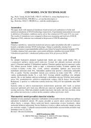
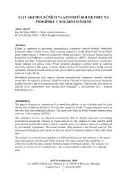
Temperature distribution on the internal<br />
pump assembly<br />
by Rahul Chikurde and S. Manivasagam, Kirloskar Copeland Ltd., Karad, India<br />
The complex fluid flow and heat transfer<br />
phenomena in hermetic compressors are<br />
very difficult to analyze theoretically. Because<br />
there is insufficient understanding of the physics<br />
involved, assumptions are often made in order<br />
to solve these problems analytically, and these<br />
assumptions can have a negative impact on<br />
the quality of the results. To cope with today’s<br />
high-energy efficiency standards, there is a need<br />
to overcome these limitations, so that the flow<br />
and heat transfer inside the compressor can<br />
be better understood.<br />
At Kirloskar Copeland in Karad, India, CFD<br />
has been used to perform a more rigorous analysis<br />
of the entire compressor domain, including<br />
the suction and discharge gas paths. The<br />
ability of the FLUENT code to deal with conjugate<br />
heat transfer (conduction and convection)<br />
in a turbulent flow encouraged engineers to<br />
perform a flow and thermal analysis for the<br />
entire compressor. The effort has helped predict<br />
such important characteristics as motor<br />
winding temperature, and velocity and pressure<br />
fields across the domain. The powerful<br />
visualization tools have made it easy to see the<br />
overall flow patterns along the gas flow paths.<br />
The thermal performance of the compressor<br />
plays an important role in the optimal working<br />
of the appliance in which it is fitted. Hence,<br />
it is necessary to carefully simulate the heat<br />
transfer inside the compressor, since it governs<br />
the energy efficiency of the whole system.<br />
The most important contributors to the<br />
thermal performance are the suction gas superheating,<br />
which is mainly due to heat sources<br />
20 Fluent NEWS spring 2002<br />
related to the copper and iron (or core) losses<br />
and the heat of compression, and volumetric<br />
and energy losses occurring in the suction and<br />
discharge gas paths. Other heat sources inside<br />
the compressor are due to rotor and frictional<br />
losses. Each of these effects is represented by<br />
a volumetric heat source in the FLUENT model.<br />
To date, the CFD analysis has provided predictions<br />
for the temperatures on numerous<br />
components inside the compressor. This information<br />
has been used to help design more<br />
efficient motors (with better cooling) and select<br />
the appropriate Internal Overload Protector<br />
(OLP), which protects the motor from overheating<br />
under adverse conditions.<br />
The results of the numerical simulation have<br />
been validated using an experimental set-up<br />
that uses conventional thermocouples to perform<br />
thermal mapping of the compressor. The<br />
numerical solution has been found to agree<br />
well with the experimental results. Because<br />
the simulation resembles the actual testing of<br />
the compressor on the calorimeter test rig under<br />
specified conditions, the compressor behavior<br />
can be visualized and thoroughly understood<br />
well before the prototypes are built and<br />
tested. If need be, the compressor design can<br />
be altered to obtain the target performance.<br />
The success of the validation work has given<br />
Kirloskar Copeland engineers the necessary confidence<br />
to use CFD during the product development<br />
stage for new equipment, thereby<br />
reducing the number of prototypes for trial<br />
and error, and the total design cycle time by<br />
almost 30%. ■<br />
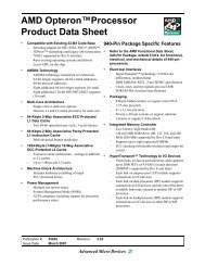
Path lines illustrate the flow through<br />
the compressor<br />
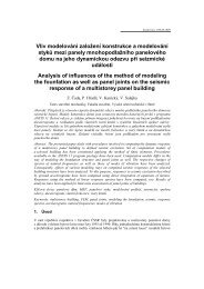
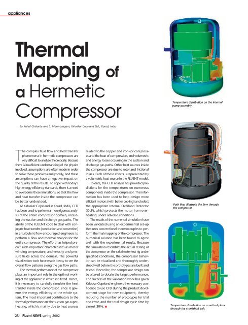
Temperature distribution on a vertical plane<br />
through the crankshaft axis