Einbau- und Betriebsanleitung MPB en - Richter Pumps
Einbau- und Betriebsanleitung MPB en - Richter Pumps
Einbau- und Betriebsanleitung MPB en - Richter Pumps

Create successful ePaper yourself
Turn your PDF publications into a flip-book with our unique Google optimized e-Paper software.
INSTALLATION AND OPERATING MANUAL<br />
Translation of the original manual<br />
Series <strong>MPB</strong><br />
Peripheral <strong>Pumps</strong><br />
with Magnetic Drive<br />
Close-coupled design<br />
size 25-25-115<br />
Keep for future use!<br />
This operating manual must be strictly observed before<br />
transport, installation, operation and maint<strong>en</strong>ance<br />
Subject to change without notice.<br />
Reproduction is g<strong>en</strong>erally permitted with indication<br />
of the source.<br />
© <strong>Richter</strong> Chemie-Technik GmbH<br />
9240-050-<strong>en</strong> Revision 10 Edition 03/2010
Series <strong>MPB</strong>, close-coupled design Page 2<br />
List of Cont<strong>en</strong>ts<br />
List of Cont<strong>en</strong>ts ........................................ 2<br />
Relevant docum<strong>en</strong>ts ................................. 3<br />
1 Technical data ...................................... 3<br />
1.1 Tight<strong>en</strong>ing torques ....................................... 3<br />
1.2 Type plate, dry-running, ATEX-and housing<br />
markings ...................................................... 4<br />
1.3 Spare parts .................................................. 4<br />
2 Notes on safety .................................... 4<br />
2.1 Int<strong>en</strong>ded use ................................................ 5<br />
2.2 For the customer/operator ........................... 5<br />
2.3 For maint<strong>en</strong>ance ......................................... 6<br />
2.4 Conversion work and production of spare<br />
parts by the customer .................................. 6<br />
2.5 Improper operation ...................................... 6<br />
2.6 Special requirem<strong>en</strong>ts for explosion protection<br />
................................................................. 6<br />
2.6.1 Filling the unit ................................................... 6<br />
2.6.2 Special operating conditions ............................ 6<br />
2.6.3 Chargeable liquids ........................................... 6<br />
2.6.4 Id<strong>en</strong>tification ..................................................... 7<br />
2.6.5 Check of the direction of rotation ..................... 7<br />
2.6.6 Mode of operation of the pump ........................ 7<br />
2.6.7 Temperature limits ........................................... 7<br />
2.6.8 Maint<strong>en</strong>ance ..................................................... 8<br />
2.6.9 Electric peripheral equipm<strong>en</strong>t ........................... 8<br />
3 Transport, storage and disposal ........ 9<br />
3.1 Return consignm<strong>en</strong>ts .................................. 9<br />
3.2 Disposal ....................................................... 9<br />
4 Product description ........................... 10<br />
5 Installation .......................................... 11<br />
5.1 Safety regulations ...................................... 11<br />
5.2 Installation of pump/unit ............................ 11<br />
5.3 Alignm<strong>en</strong>t of pump - motor ........................ 11<br />
5.4 Piping......................................................... 11<br />
5.4.1 Nominal size ................................................... 11<br />
5.4.2 Nozzle loads ................................................... 11<br />
5.4.3 Suction line ..................................................... 12<br />
5.4.4 Supply lines .................................................... 12<br />
5.4.5 Discharge line ................................................ 12<br />
5.4.6 V<strong>en</strong>ting and draining ...................................... 12<br />
5.5 Pipe fittings ................................................ 12<br />
5.6 Monitoring facilities .................................... 13<br />
5.7 Drive .......................................................... 13<br />
5.8 Electric connection .................................... 13<br />
6 Commissioning / Shutdown ............. 14<br />
6.1 Initial commissioning .................................. 14<br />
6.1.1 Filling the pump housing ................................ 14<br />
6.1.2 Start-up .......................................................... 14<br />
6.2 Operating limits .......................................... 14<br />
6.2.1 Min./max. flow rate ......................................... 14<br />
6.3 Shutdown ................................................... 14<br />
6.4 Restarting .................................................. 14<br />
6.5 Improper operations and their consequ<strong>en</strong>ces<br />
(examples) ................................................. 15<br />
7 Maint<strong>en</strong>ance ....................................... 16<br />
7.1 Screw connections of the housing ............. 16<br />
7.2 Motor .......................................................... 16<br />
7.3 Cleaning ..................................................... 16<br />
7.4 Stand-by pumps ......................................... 16<br />
7.5 Notes on dismantling ................................. 16<br />
7.5.1 Protective clothing .......................................... 16<br />
7.5.2 Magnetic fields ............................................... 16<br />
7.6 Dismantling ................................................ 16<br />
7.6.1 Can, can insert and intermediate ring ........... 17<br />
7.6.2 Dismantling of drive unit ................................. 17<br />
7.7 Notes on assembly .................................... 17<br />
7.8 Assembly ................................................... 17<br />
7.8.1 Assembly of drive unit .................................... 17<br />
7.8.2 Can, can insert and intermediate ring ........... 18<br />
7.8.3 Housing, right-hand ring channel and right-hand<br />
bearing bush .................................................. 18<br />
7.8.4 Assembly housing, impeller and inner magnet<br />
assembly ........................................................ 18<br />
7.8.5 Drain (if provided) .......................................... 18<br />
7.9 Tests .......................................................... 18<br />
8 Faults .................................................. 19<br />
9 Sectional drawing .............................. 20<br />
9.1 Leg<strong>en</strong>d sectional drawing .......................... 20<br />
9.2 Sectional drawing <strong>MPB</strong>, housing in L-position<br />
............................................................... 21<br />
9.3 Sectional drawing <strong>MPB</strong>, housing in V-<br />
position....................................................... 22<br />
10 Assembly aids ................................... 23<br />
10.1 Boring template .......................................... 23<br />
10.2 Assembly/Dismantling aid for inner magnet<br />
assembly .................................................... 23<br />
10.3 Dismantling ring ......................................... 24<br />
9240-050-<strong>en</strong> Revision 10<br />
TM 7813 Edition 03/2010
Series <strong>MPB</strong>, close-coupled design Page 3<br />
Relevant docum<strong>en</strong>ts<br />
♦ Data sheet<br />
♦ Works certificate<br />
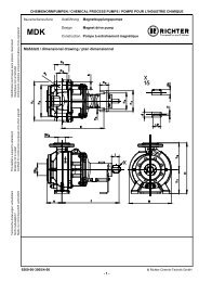
♦ Sectional drawing <strong>MPB</strong><br />
nozzle position L of the housing 9240-00-3000<br />
nozzle position V of the housing 9240-00-3001<br />
♦ Installation drawing 9240-00-3003<br />
♦ Dim<strong>en</strong>sional drawing drain connection9240-00-3002<br />
♦ Performance curves<br />
♦ Spare parts list<br />
♦ Operating manual and declaration of conformity<br />
motor<br />
App<strong>en</strong>dix to the operating instructions<br />
♦ Operational limits see 9240-00-3030<br />
♦ Declaration of conformity with ATEX<br />
♦ Declaration of conformity without ATEX<br />
♦ Form for Safety Information Concerning the<br />
Contamination QM 0912-16-2001_<strong>en</strong><br />
On request:<br />
♦ Magnetic drive data <strong>Richter</strong> TIS 0543-03-0001<br />
♦ Publication: "C<strong>en</strong>trifugal Pump Operation without<br />
NSPH Problems"<br />
♦ Publication "Safe Operation of Magnetic Drive<br />
<strong>Pumps</strong>“<br />
1 Technical data<br />
Manufacturer :<br />
<strong>Richter</strong> Chemie-Technik GmbH<br />
Otto-Schott-Str. 2<br />
D-47906 Kemp<strong>en</strong><br />
Telephone: +49 (0) 2152 146-0<br />
Fax: +49 (0) 2152 146-190<br />
E-Mail: richter-info@idexcorp.com<br />
Internet: http://www.richter-ct.com<br />
Authorised person acc. to machinery directive<br />
2006/42/EG: Gregor Kleining<br />
Designation :<br />
Peripheral pump with magnetic drive, series <strong>MPB</strong>,<br />
close-coupled design<br />
Technical specifications to ISO 15783 and DIN ISO<br />
5199<br />
Flange connecting dim<strong>en</strong>sions:<br />
DIN EN 1092-2, type B (ISO 7005-2, type B) PN 16<br />
or flanges drilled to ASME 16.5, Class 150<br />
ATEX 95 Directive 94/9/EC<br />
Machine Directive 2006/42/EC<br />
Materials :<br />
Pressure-bearing parts:<br />
ductile cast iron EN-JS 1049 to DIN EN 1563 (0.7043<br />
DIN 1693), carbon fibre composite material<br />
Wetted parts:<br />
PFA, PTFE, SSiC, FKM/FFKM,<br />
and see data sheet<br />
Flow rate :<br />
up to 6 m 3 /h (at 2900 -1 /min)<br />
Delivery head : up to 100 m LC (at 2900 -1 /min)<br />
Housing discharge pressure : max. 16 bar<br />
detailed data see operational limits<br />
Temperature range : - 60 °C to + 150 °C<br />
Note: Consult the manufacturer for higher pressures<br />
and lower or higher temperatures.<br />
Temperature classes : see Section 2.6.7<br />
Noise capacity level : L WA = ≤ 70 dB acc. to<br />
DIN EN ISO 9614-2<br />
Admissible ambi<strong>en</strong>t conditions for pumps<br />
acc. to directive 94/9/ EC (ATEX 95) :<br />
Ambi<strong>en</strong>t temperature range: -20°C to +40°C<br />
(higher temperature after consulting the manufacturer)<br />
Ambi<strong>en</strong>t pressure range : 0,8 bar abs to 1,1 bar abs<br />
Weight :<br />
See data sheet<br />
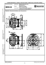
Dim<strong>en</strong>sions : See installation drawing<br />
Size : 25-25-115<br />
1.1 Tight<strong>en</strong>ing torques<br />
Screws greased, tight<strong>en</strong> in diametrically opposite<br />
sequ<strong>en</strong>ce.<br />
No. x Size Nm<br />
Cover flange 8 x M 10 20<br />
Housing flange 8 x M 10 25<br />
Drain flange 2 x M 8 10<br />
Pipe screws, flanges to DIN/ISO<br />
DN No. x size Tight<strong>en</strong>ing torque<br />
[mm] [DIN/ISO] [Nm]<br />
25 4 x M 12 10<br />
9240-050-<strong>en</strong> Revision 10<br />
TM 7813 Edition 03/2010
Series <strong>MPB</strong>, close-coupled design Page 4<br />
Pipe screws, DIN/ISO flanges drilled to ASME<br />
Dry-running:<br />
DN No. x size Tight<strong>en</strong>ing torque<br />
[mm] [inch] [ASME] [Nm] [in-lbs]<br />
25 1“ 4 x ½“ 8 70<br />
1.2 Type plate, dry-running, ATEXand<br />
housing markings<br />
The stainless steel type plate is firmly riveted to the<br />
lantern:<br />
If the operator attaches his id<strong>en</strong>tification, it must be<br />
<strong>en</strong>sured that the pump matches the application in<br />
question.<br />
Example of type plate:<br />
ATEX marking:<br />
Housing id<strong>en</strong>tification:<br />
The following are visible on the housing according to<br />
DIN EN 19:<br />
♦ Nominal size<br />
♦ Rated pressure<br />
♦ Housing material<br />
♦ Manufacturer's id<strong>en</strong>tification<br />
♦ Melt number/Fo<strong>und</strong>ry id<strong>en</strong>tification<br />
♦ Fo<strong>und</strong>ry date<br />
1.3 Spare parts<br />
Spare parts for two years of continuous operation in<br />
accordance with DIN 24296 and in consultation with<br />
the manufacturer<br />
2 Notes on safety<br />
This operating manual contains f<strong>und</strong>am<strong>en</strong>tal<br />
information which is to be observed during installation,<br />
operation and maint<strong>en</strong>ance.<br />
It must be read before installation and<br />
commissioning!<br />
This operating manual must always be available at the<br />
place of use of the machine/plant.<br />
In addition to the g<strong>en</strong>eral notes on safety <strong>und</strong>er the<br />
main heading “Safety”, special notes on safety are<br />
included at other points and must be observed.<br />
Installation, operation and maint<strong>en</strong>ance are to be<br />
performed by qualified staff.<br />
The area of responsibility, authority and supervision of<br />
the staff must be exactly regulated by the customer.<br />
If the staff do not have the necessary expertise, they<br />
are to be trained and instructed.<br />
If necessary, this can be provided by the<br />
manufacturer/supplier on behalf of the machine<br />
operator.<br />
G<strong>en</strong>eral hazard symbol! People may be put<br />
at risk.<br />
Safety symbol! The pump and its function<br />
may be put at risk if this safety symbol is not<br />
observed.<br />
9240-050-<strong>en</strong> Revision 10<br />
TM 7813 Edition 03/2010<br />
EU marking! Explosion-protected equipm<strong>en</strong>t<br />
must be id<strong>en</strong>tified for work in pot<strong>en</strong>tially<br />
explosive areas.<br />
Warning of a magnetic field!<br />
Warning of electric power!<br />
This warning sign must be used if people<br />
with a pacemaker are at risk, e.g. from a<br />
strong magnetic field.<br />
It is imperative to observe signs attached directly to<br />
the pump / unit, e.g.:<br />
♦ Direction of rotation arrow<br />
♦ Warning against dry-running<br />
and they are to be kept legible.<br />
Non-observance of the notes on safety may result<br />
in the loss of any and all claims for damages.<br />
Non-observance may involve the following hazards :<br />
♦ Failure of important functions of the machine/plant.<br />
♦ Failure of electronic equipm<strong>en</strong>t and measuring<br />
instrum<strong>en</strong>ts due to magnetic fields.
Series <strong>MPB</strong>, close-coupled design Page 5<br />
♦ Risk to people and their personal property from<br />
magnetic fields.<br />
♦ Risk to people from electric, mechanical and<br />
chemical effects.<br />
♦ Risks to the <strong>en</strong>vironm<strong>en</strong>t through leaks of<br />
hazardous substances.<br />
If the unit is used in pot<strong>en</strong>tially explosive<br />
areas, special att<strong>en</strong>tion is to be paid to the<br />
sections id<strong>en</strong>tified with “Ex” in this<br />
operating manual.<br />
2.1 Int<strong>en</strong>ded use<br />
<strong>Richter</strong> pumps of the series <strong>MPB</strong> are plastic-lined<br />
peripheral pumps for the leak-free conveyance of<br />
aggressive, toxic, pure and inflammable liquids. These<br />
liquids must not contain any solids.<br />
Gas cont<strong>en</strong>ts of up to 30% may be <strong>en</strong>trained. If gas is<br />
<strong>en</strong>trained in an explosive area, it must be <strong>en</strong>sured that<br />
no explosive atmosphere <strong>en</strong>ters the pump as a result<br />
of the gas conveyed.<br />
The pump is equipped with a perman<strong>en</strong>t magnetic<br />
synchronous drive.<br />
The observance of the specified physical<br />
limits is important for perfect functioning and<br />
safe operation, especially with regard to<br />
explosion protection to prev<strong>en</strong>t pot<strong>en</strong>tial sources of<br />
ignition (see Section 2.6):<br />
♦ It must be <strong>en</strong>sured that the pump is always filled<br />
with liquid during operation.<br />
♦ For safe pump operation, we recomm<strong>en</strong>d a flow<br />
rate which lies betwe<strong>en</strong> 0.3 and 1.1 Q opt . The<br />
maximum operating temperature must never be<br />
exceeded. See Section 2.6.7. In case of doubt,<br />
you must consult the manufacturer.<br />
♦ The manufacturer must be consulted in the ev<strong>en</strong>t<br />
of <strong>en</strong>trainm<strong>en</strong>t of gas >5% in order to avoid a lack<br />
of lubrication and dry-running. If gas is <strong>en</strong>trained in<br />
an explosive area, it must be <strong>en</strong>sured that no<br />
explosive atmosphere <strong>en</strong>ters the pump as a result<br />
of the gas conveyed.<br />
♦ The plant NPSH value (NPSHA) should be 0.5 m<br />
higher than the NPSH value of the pump<br />
(NPSHR). See also Section 5.4.1.<br />
♦ Owing to its design the pump can draw in media<br />
on its own within certain operating limits.<br />
It is imperative for the pump to be filled completely<br />
prior to self-priming.<br />
For self-priming in or out of an explosive area it<br />
must be <strong>en</strong>sured that no pot<strong>en</strong>tially explosive<br />
atmosphere can form.<br />
This can be achieved by superimposing the plant<br />
with an inert gas (e.g. nitrog<strong>en</strong>).<br />
The medium must not exceed the medium<br />
temperature shown in the table in Section 2.6.7<br />
nor its boiling temperature. This can, for example,<br />
be <strong>en</strong>sured by a temperature monitor.<br />
Improper operation, ev<strong>en</strong> for a short period,<br />
may result in serious damage to the unit.<br />
In connection with explosion protection, pot<strong>en</strong>tial<br />
sources of ignition (overheating, electrostatic and<br />
induced charges, mechanical and electric sparks) may<br />
result from these improper operation; their occurr<strong>en</strong>ce<br />
can only be prev<strong>en</strong>ted by adhering to the int<strong>en</strong>ded<br />
use.<br />
Furthermore, refer<strong>en</strong>ce is made in this connection to<br />
the Directive 95/C332/06 (ATEX 118a) which contains<br />
the minimum regulations for improving the<br />
occupational health and safety of the workers who<br />
may be at risk from an explosive atmosphere.<br />
This unit must not be operated above the<br />
values specified in the data sheet as regards<br />
the fluid to be conveyed, flow rate, speed,<br />
d<strong>en</strong>sity, delivery head and operating temperature as<br />
well as the motor rating.<br />
The instructions contained in the operating<br />
manual or contract docum<strong>en</strong>tation must be<br />
observed; if necessary consult the manufacturer.<br />
All important features are docum<strong>en</strong>ted in the data<br />
sheet included in the scope of delivery.<br />
In the ev<strong>en</strong>t of operating conditions other than those<br />
described in the data sheet, the following are to be<br />
checked again:<br />
♦ design of the pump<br />
♦ design of the accessories<br />
♦ resistance of the materials.<br />
2.2 For the customer/operator<br />
The following must be observed:<br />
♦ The notes on safety contained in this operating<br />
manual,<br />
♦ the prevailing regulations on accid<strong>en</strong>t prev<strong>en</strong>tion,<br />
♦ in-house work, operating and safety regulations of<br />
the customer.<br />
♦ Hot or cold machine parts must be protected by<br />
the customer against being touched.<br />
♦ No protective facilities may be removed wh<strong>en</strong> the<br />
machine is in operation.<br />
♦ The ring bolt 900/1 must not be removed or<br />
loos<strong>en</strong>ed as deposits could form betwe<strong>en</strong><br />
the drive magnet assembly and the lantern.<br />
For example, overheating and thus pot<strong>en</strong>tial<br />
sources of ignition could arise due to frictional<br />
<strong>en</strong>ergy.<br />
♦ Hazards due to electricity are to be excluded.<br />
♦ Leaks of hazardous media (e.g. explosive, toxic,<br />
hot) must be removed so that no risk arises for<br />
people and the <strong>en</strong>vironm<strong>en</strong>t. The statutory<br />
provisions are to be observed.<br />
Caution wh<strong>en</strong> using the units in pot<strong>en</strong>tially<br />
explosive area! Improper operation must be<br />
prev<strong>en</strong>ted.<br />
9240-050-<strong>en</strong> Revision 10<br />
TM 7813 Edition 03/2010
Series <strong>MPB</strong>, close-coupled design Page 6<br />
2.3 For maint<strong>en</strong>ance<br />
In principle, work on the unit may only be performed<br />
wh<strong>en</strong> it is at a standstill.<br />
It is imperative to observe the procedure for stopping<br />
the machine described in this operating manual. See<br />
Section 6.3.<br />
<strong>Pumps</strong> which convey media which are a health<br />
hazard must be decontaminated.<br />
All safety and protective facilities must be remounted<br />
or <strong>en</strong>abled immediately after the <strong>en</strong>d of work.<br />
In the assemble state, if the safety notes (see also<br />
Section 5.1 and 7.5.2) are observed, the magnetic<br />
drives do not cause any risks or have any affect on<br />
the <strong>en</strong>vironm<strong>en</strong>t.<br />
During dismantling and assembly as well as<br />
during transport and storage of the magnetic<br />
drives as single compon<strong>en</strong>ts, the notes on<br />
safety in Section 7.5.2 must be observed.<br />
The points listed in Section 6.1 must be followed<br />
before recommissioning.<br />
2.4 Conversion work and<br />
production of spare parts by<br />
the customer<br />
Conversion of or changes to the machine are only<br />
admissible after consultation with the manufacturer.<br />
Original spare parts and accessories authorised by<br />
the manufacturer serve to <strong>en</strong>hance safety.<br />
The use of other parts may annul the liability for any<br />
resultant consequ<strong>en</strong>ces.<br />
2.5 Improper operation<br />
The operational safety of the machine supplied is only<br />
guaranteed if it is used properly in accordance with<br />
Section 2.1 of this operating manual.<br />
The operating limits specified in the data sheet must<br />
<strong>und</strong>er no circumstances be exceeded.<br />
2.6 Special requirem<strong>en</strong>ts for<br />
explosion protection<br />
If the units are used in pot<strong>en</strong>tially explosive areas, the<br />
measures and notes in Sections 2.6.1 to 2.6.9 are<br />
imperative to guarantee the explosion protection.<br />
If the customer cannot <strong>en</strong>sure this, we<br />
recomm<strong>en</strong>d that appropriate monitoring<br />
facilities be provided.<br />
All auxiliary, heating and cooling systems<br />
must also be carefully filled.<br />
2.6.2 Special operating conditions<br />
In the standard design the can chamber and<br />
the plain bearings are cooled and lubricated<br />
by a flushing flow.<br />
The cooling flow may be interrupted and an<br />
inadmissible rise in temperature may occur due to<br />
properties of the liquid (e.g. sticking, clogging, ingress<br />
of gas etc.). Appropriate monitoring facilities are to be<br />
provided. See Section 5.6.<br />
For safe pump operation, we recomm<strong>en</strong>d a flow rate<br />
of 0.3 to 1.1 Q opt . If the pump is operated outside this<br />
range, it must be <strong>en</strong>sured that the max. admissible<br />
flow rate according to the pump characteristic curve is<br />
not exceeded and that the max. admissible operating<br />
temperature according to Section 2.6.7 is observed.<br />
If the flow rate is too high, the differ<strong>en</strong>tial pressure<br />
upstream and downstream of the plain bearings could<br />
fall so much that a lack of lubrication or dry-running<br />
may occur.<br />
If the flow rate is too low, the medium may heat up so<br />
much owing to the fluid friction that the max.<br />
admissible surface temperature of the relevant<br />
temperature class is exceeded<br />
Overloading, overheating, non-observance of the<br />
design data or the incorrect selection of the magnetic<br />
drive can lead to the decoupling of the inner and outer<br />
magnet assemblies. As a result, eddy curr<strong>en</strong>ts are<br />
induced on the inner and outer magnet assemblies<br />
and an inadmissible rise in temperature may occur.<br />
The situation is to be remedied by providing<br />
appropriate monitoring facilities. See Section 5.6.<br />
The plant NPSH value (NPSHA) should be 0.5 m<br />
higher than the NPSH value of the pump (NPSHR) to<br />
prev<strong>en</strong>t a lack of lubrication or dry-running of the plain<br />
bearings.<br />
2.6.3 Chargeable liquids<br />
For operation with chargeable liquids with a<br />
conductivity < 10 -8 S/m inert gas must be used<br />
for flushing during drain if the lining of the<br />
pump is non-conductive. See Section 6.3.<br />
2.6.1 Filling the unit<br />
During pump operation the wetted interior of<br />
the pump must always be filled with the liquid<br />
medium.<br />
This prev<strong>en</strong>ts any explosive atmosphere and the risk<br />
of dry-running.<br />
9240-050-<strong>en</strong> Revision 10<br />
TM 7813 Edition 03/2010
Series <strong>MPB</strong>, close-coupled design Page 7<br />
2.6.4 Id<strong>en</strong>tification<br />
The id<strong>en</strong>tification on the pump relates to the<br />
pump section. A separate declaration of<br />
conformity must be provided for the motor<br />
and for other attachm<strong>en</strong>ts as well as corresponding<br />
id<strong>en</strong>tification.<br />
Example of the id<strong>en</strong>tification of the pump section:<br />
II2GD IIC TX X.<br />
For assembling the pump with compon<strong>en</strong>ts which are<br />
not explosion-protected (e.g. motor, shaft coupling), it<br />
is recomm<strong>en</strong>ded to mask or remove the "pot<strong>en</strong>tially<br />
explosive" id<strong>en</strong>tification from the pump compon<strong>en</strong>t<br />
and, if necessary, from other accessories.<br />
In this case the declaration of conformity applies<br />
without ATEX id<strong>en</strong>tification.<br />
At surface temperatures which dep<strong>en</strong>d primarily on<br />
operating conditions, DIN EN 13463-1 Chapter 9.3<br />
allows no temperature class or temperature to be<br />
indicated.<br />
The temperature class must be determined by the<br />
operator in accordance with Section 2.6.7<br />
“Temperature Limits”.<br />
2.6.5 Check of the direction of rotation<br />
If there is also a risk of explosion during the<br />
installation phase, the check of the direction of<br />
rotation must <strong>und</strong>er no circumstances be<br />
conducted by briefly switching on the unfilled pump in<br />
order to prev<strong>en</strong>t an inadmissible rise in temperature at<br />
the plain bearings.<br />
We recomm<strong>en</strong>d you to only perform a check<br />
of the direction of rotation with filled pump and<br />
with a rotating field instrum<strong>en</strong>t. See also<br />
Section 6.1.2.<br />
2.6.6 Mode of operation of the pump<br />
The pump may only be started with the suction side<br />
shut-off elem<strong>en</strong>t fully op<strong>en</strong>ed and the discharge side<br />
shut-off elem<strong>en</strong>t slightly op<strong>en</strong>ed. Start-up against a<br />
closed check valve is also possible. The discharge<br />
side shut-off elem<strong>en</strong>t is to be regulated to the<br />
operating design point directly after run-up.<br />
See also Section 5.4.1.<br />
Operation with closed shut-off elem<strong>en</strong>ts in the<br />
suction and/or discharge lines is not permitted!<br />
There is a risk that ev<strong>en</strong> after a short time<br />
high surface temperatures on the pump<br />
housing may occur owing to rapid heating of<br />
the liquid in the pump interior.<br />
A rapid rise in the pressure inside the pump<br />
involves the risk of overloading to the point of<br />
bursting.<br />
The pump must not be in operation in the<br />
unfilled or partially filled state (dry<br />
running). This results in serious damage<br />
to the pump and additional risks to the<br />
<strong>en</strong>vironm<strong>en</strong>t can arise.<br />
Dry-running cannot only occur with an<br />
insuffici<strong>en</strong>tly filled interior but also in the ev<strong>en</strong>t<br />
of high gas cont<strong>en</strong>ts in the liquid medium.<br />
Operation of the pump outside the admissible<br />
operating range may also lead to dry-running (e.g.<br />
due to evaporation in the interior).<br />
2.6.7 Temperature limits<br />
In the normal operating condition the highest<br />
temperatures are to be expected on the<br />
surface of the pump housing.<br />
We would like to point out that, <strong>und</strong>er extreme<br />
operating (medium temperature > 160°C) and ambi<strong>en</strong>t<br />
conditions (ambi<strong>en</strong>t temperature ><br />
30°C), temperatures of over 130°C may arise on the<br />
surface of the pump housing.<br />
In the case of liquids > 40 °C the surface temperature<br />
of the pump housing is g<strong>en</strong>erally lower than the<br />
temperature of the liquid as the plastic lining has an<br />
insulating effect.<br />
If the pump is heated (e.g. heating jacket), it<br />
must be <strong>en</strong>sured that the temperature classes<br />
prescribed in the annex are observed.<br />
The not heated pump surface must have free contact<br />
with the <strong>en</strong>vironm<strong>en</strong>t.<br />
During operation of the pump it must be<br />
<strong>en</strong>sured that excessive deposits of dust are<br />
prev<strong>en</strong>ted (regular cleaning) in order to<br />
prev<strong>en</strong>t the pump surface from heating to above the<br />
admissible temperature.<br />
The plant customer must <strong>en</strong>sure that the<br />
prescribed operating temperature is observed.<br />
The maximum admissible temperature of the<br />
liquid medium at the pump inlet dep<strong>en</strong>ds on the<br />
temperature class and the selected lining material<br />
required in each case.<br />
The following always applies: No inadmissible<br />
temperatures may be introduced into the motor and<br />
the specifications of the motor manufacturer must be<br />
observed.<br />
The temperature limits of the fluid giv<strong>en</strong> in Table 2<br />
only apply wh<strong>en</strong> motors are used where the motor<br />
manufacturer permits at least the following<br />
temperatures for the motor flange and motor shaft:<br />
9240-050-<strong>en</strong> Revision 10<br />
TM 7813 Edition 03/2010
Series <strong>MPB</strong>, close-coupled design Page 8<br />
Table 1<br />
Temperature<br />
class<br />
Motor flange<br />
Motor shaft<br />
T6 70 °C 70 °C<br />
T5 70 °C 80 °C<br />
T4 75 °C 85 °C<br />
T3 80 °C 100 °C<br />
T2 80 °C 100 °C<br />
T1 80 °C 100 °C<br />
At the same time the specified max. admissible<br />
ambi<strong>en</strong>t temperature of 40 °C must not be exceeded.<br />
Table 2 below indicates the admissible medium<br />
temperature, dep<strong>en</strong>ding on the pump design, as a<br />
function of the temperature class in accordance with<br />
EN 13463-1.<br />
Table 2<br />
Temperature class<br />
accord. EN 13463-1<br />
Limit values of the<br />
temperature of the liquid<br />
PFA/PFA-L<br />
T6 (85 °C) 75 °C 1)<br />
T5 (100 °C) 90 °C 1)<br />
T4 (135 °C) 125 °C 1)<br />
T3 (200 °C) 150 °C<br />
T2 (300 °C) 150 °C<br />
T1 (450 °C) 150 °C<br />
1) The limit values specified for the temperature of the medium at<br />
the pump inlet are determined for the most unfavourable case<br />
(high speed, low flow, low heat capacity of the medium, ....).<br />
Under favourable operating conditions the limit values specified<br />
may be increased by up to 5 K after consultation with the<br />
manufacturer.<br />
In the case of motors with the type of protection<br />
"increased safety", no or low temperature <strong>en</strong>tries are<br />
g<strong>en</strong>erally permitted for the motor shaft and motor<br />
flange related to an ambi<strong>en</strong>t temperature of 40 °C.<br />
In these cases the max. admissible medium<br />
temperature is 20 K above the temperature which may<br />
be introduced into the motor.<br />
e.g.: Max. motor shaft temperature: 60°C<br />
Max. motor flange temperature: 65°C<br />
This results in a maximum medium temperature for<br />
the pump of 80 °C (60 °C + 20 K)..<br />
2.6.8 Maint<strong>en</strong>ance<br />
For safe and reliable operation, it must be<br />
<strong>en</strong>sured with regular inspection intervals that<br />
the unit is properly serviced and kept in a<br />
perfect technical condition.<br />
If auxiliary systems (e.g. external flushing, cooling,<br />
heating) are installed, a check must be made to see<br />
whether monitoring facilities are required to safeguard<br />
their operation.<br />
In regard to media containing solids, the maint<strong>en</strong>ance<br />
intervals must be set by the operator in accordance<br />
with the conditions of operation.<br />
2.6.9 Electric peripheral equipm<strong>en</strong>t<br />
Electric peripheral equipm<strong>en</strong>t, e.g. pressure,<br />
temperature and flow s<strong>en</strong>sors etc. must comply with<br />
the prevailing safety requirem<strong>en</strong>ts and explosion<br />
protection provisions.<br />
Regular checks of the motor bearings in<br />
accordance with the operating manual of the<br />
motor manufacturer. Observe ATEX notes.<br />
9240-050-<strong>en</strong> Revision 10<br />
TM 7813 Edition 03/2010
Series <strong>MPB</strong>, close-coupled design Page 9<br />
3 Transport, storage and disposal<br />
The pump or the unit must be transported<br />
properly. It must be <strong>en</strong>sured that during<br />
transport the pump/unit remains in the<br />
horizontal position and does not slip out of the<br />
transport susp<strong>en</strong>sion points.<br />
The ring bolts of the pump and the motor must be<br />
used to transport the <strong>en</strong>tire unit, i.e. pump with<br />
baseplate and motor. See Fig. 1.<br />
The slinging ropes must not be attached to free shaft<br />
<strong>en</strong>ds.<br />
3.1 Return consignm<strong>en</strong>ts<br />
<strong>Pumps</strong> which have conveyed aggressive or toxic<br />
media must be well flushed and cleaned<br />
before being returned to the manufacturer's<br />
works.<br />
It is imperative to <strong>en</strong>close a safety information<br />
sheet / g<strong>en</strong>eral safety certificate on the field of<br />
application with the return consignm<strong>en</strong>t.<br />
Pre-printed forms are <strong>en</strong>closed with the installation<br />
and operating manual.<br />
Safety precautions and decontamination methods are<br />
to be m<strong>en</strong>tioned.<br />
3.2 Disposal<br />
Parts of the pump may be contaminated with medium<br />
which is detrim<strong>en</strong>tal to health and the <strong>en</strong>vironm<strong>en</strong>t<br />
and therefore cleaning is not suffici<strong>en</strong>t.<br />
Risk of personal injury or damage to the<br />
<strong>en</strong>vironm<strong>en</strong>t due to the medium or oil!<br />
Fig. 1<br />
Directly after receipt of the goods, the<br />
consignm<strong>en</strong>t must be checked for complet<strong>en</strong>ess<br />
and any in-transit damage.<br />
Damaged pumps must not be installed in the plant.<br />
Wh<strong>en</strong> unpacking magnetic drives as single<br />
parts, the relevant notes in Section 7.5.2<br />
must be observed.<br />
Handle goods carefully to prev<strong>en</strong>t damage.<br />
Flange covers serve as protection during transport<br />
and must not be removed.<br />
If the unit is not installed immediately after delivery, it<br />
must be put into proper storage.<br />
The product should be stored in a dry and vibrationfree,<br />
well v<strong>en</strong>tilated room at as constant a<br />
temperature as possible.<br />
Elastomers are to be protected against UV light.<br />
In g<strong>en</strong>eral, a storage period of 10 years should not be<br />
exceeded. An admissible storage period of 4 years<br />
applies to elastomers made of NBR.<br />
If magnetic drives are stored as single parts,<br />
the relevant notes in Section 7.5.2 are to be<br />
observed.<br />
In the case of prolonged storage conservation<br />
ag<strong>en</strong>ts on machined compon<strong>en</strong>t surfaces and packing<br />
with a desiccant may be necessary.<br />
♦ Wear protective clothing wh<strong>en</strong> work is<br />
performed on the pump.<br />
♦ Prior to the disposal of the pump:<br />
Collect any medium, oil etc. which has escaped<br />
and dispose of it in accordance with the local<br />
regulations.<br />
Neutralise any medium residues in the pump.<br />
♦ Separate pump materials (plastics, metals etc.)<br />
and dispose of them in accordance with the local<br />
regulations.<br />
9240-050-<strong>en</strong> Revision 10<br />
TM 7813 Edition 03/2010
Series <strong>MPB</strong>, close-coupled design Page 10<br />
4 Product description<br />
Technical requirem<strong>en</strong>ts of the pump series <strong>MPB</strong><br />
correspond to ISO 15783 / DIN ISO 5199. The<br />
technical requirem<strong>en</strong>ts of the VDMA 24279 are<br />
satisfied.<br />
The peripheral pump belongs to the family of ring<br />
channel pumps. It is used wh<strong>en</strong> large delivery heads<br />
are to be attained at relatively low flow rates.<br />
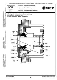
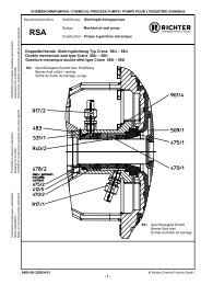
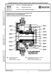
The sectional drawing shows the design of the<br />
pump. See Section 9.2 and 9.3.<br />
All compon<strong>en</strong>ts which come into contact with the<br />
medium are either plastic-lined or made of other<br />
resistant materials, e.g. silicon carbide.<br />
The nozzle position of the housing 100 may be either<br />
shaped or shaped. See sectional drawing in<br />
Sections 9.2 and 9.3.<br />
The impeller 230 has 2 lip seals. These are<br />
hydraulically pressed against the ring channels. The<br />
gap losses are therefore considerably reduced.<br />
The distance ring 504 prev<strong>en</strong>ts the right-hand bearing<br />
sleeve from "drifting".<br />
The stud 560/1 holds the ring channels in the correct<br />
position.<br />
All op<strong>en</strong>ings in the rear of the housing, apart from the<br />
lowest one, are sealed with the c<strong>en</strong>tering gaskets<br />
415/3.<br />
The lowest one remains op<strong>en</strong>:<br />
1. for draining<br />
2. for the flushing flow<br />
The flushing flow moves through the lowest op<strong>en</strong>ing<br />
into the can insert. It is returned into the housing<br />
through the right-hand bearing.<br />
The can and the cover are v<strong>en</strong>ted through the<br />
bearings.<br />
The left-hand ring channel is id<strong>en</strong>tical to the righthand<br />
ring channel.<br />
The cover 160 seals the housing and at the same time<br />
exerts pressure on the ring channels.<br />
Further design details can be se<strong>en</strong> in the sectional<br />
drawings in Sections 9.2 and 9.3.<br />
Additional information can also be fo<strong>und</strong> in the<br />
brochure.<br />
9240-050-<strong>en</strong> Revision 10<br />
TM 7813 Edition 03/2010
Series <strong>MPB</strong>, close-coupled design Page 11<br />
5 Installation<br />
5.1 Safety regulations<br />
Equipm<strong>en</strong>t which is operated in pot<strong>en</strong>tially explosive<br />
areas must satisfy the explosion protection<br />
regulations.<br />
People with a pacemaker are at risk from the<br />
strong magnetic field of the magnetic drive. It<br />
may be life-threat<strong>en</strong>ing for them to stay at a<br />
distance of less than 500 mm to the pump.<br />
5.4.1 Nominal size<br />
The operating design point of a c<strong>en</strong>trifugal pump lies<br />
at the intersection of the pump curve and the pipe<br />
curve, see Fig. 2. The pump curve is provided by the<br />
pump manufacturer. The pipe curve is determined<br />
using diagrams or PC programs.<br />
5.2 Installation of pump/unit<br />
The structural work must be prepared in<br />
accordance with the dim<strong>en</strong>sions in the<br />
installation drawing.<br />
Method of installation: on a grouted base plate and<br />
firm fo<strong>und</strong>ation<br />
Align base plate on the gro<strong>und</strong> fo<strong>und</strong>ation.<br />
Insert fo<strong>und</strong>ation bolts and grout base plate.<br />
Do not tight<strong>en</strong> the fo<strong>und</strong>ation bolts uniformly and<br />
firmly until the mortar has set.<br />
Other possibilities of alignm<strong>en</strong>t are:<br />
♦ 4-point-alignm<strong>en</strong>t<br />
♦ 4-point-alignm<strong>en</strong>t with base plate.<br />
As soon as additional installations are<br />
mounted, the stability of the <strong>en</strong>tire unit<br />
installed without a fo<strong>und</strong>ation must be<br />
checked.<br />
5.3 Alignm<strong>en</strong>t of pump - motor<br />
Special notes of the motor manufacturer are<br />
to be observed.<br />
Use supports in the direct vicinity of the bolts<br />
fo<strong>und</strong>ation/base plate.<br />
5.4 Piping<br />
Before the pump is installed, both the suction and<br />
supply lines as well as the discharge line are to be<br />
cleaned.<br />
Dirt or damage to the sealing surfaces is best avoided<br />
if the flange covers remain on the flanges until just<br />
before installation.<br />
Use flange gaskets suitable for the medium.<br />
The screw tight<strong>en</strong>ing torques in Section 1.1 are to be<br />
observed for tight<strong>en</strong>ing the flange screws.<br />
Fig. 2<br />
Under no circumstances can the nominal size of the<br />
piping be derived from the connected nominal size of<br />
the pump.<br />
The pipe nominal size can also be determined using<br />
the flow rate as a rough guide.<br />
v (m / s)<br />
3<br />
Q (m / s)<br />
=<br />
2<br />
A (m )<br />
The velocity in the suction line should not exceed<br />
2.0 m/s and 5.0 m/s in the discharge line.<br />
Wh<strong>en</strong> determining the suction line nominal size, the<br />
NPSH value (net positive suction head) must also be<br />
observed. The NPSHR value required for the pump is<br />
specified in the data sheet.<br />
The NPSHR available in the plant<br />
should be at least 0.5 m higher than<br />
the NPSHR required for the pump.<br />
Otherwise, this will lead to a drop in the delivery head,<br />
cavitation or ev<strong>en</strong> failure of the pump.<br />
5.4.2 Nozzle loads<br />
The pump can be subjected to nozzle loads in<br />
accordance with ISO 5199.<br />
Changes in the l<strong>en</strong>gth of the piping caused by<br />
temperature are to be allowed for by appropriate<br />
measures, e.g. the installation of expansion joints.<br />
9240-050-<strong>en</strong> Revision 10<br />
TM 7813 Edition 03/2010
Series <strong>MPB</strong>, close-coupled design Page 12<br />
5.4.3 Suction line<br />
The suction lines must always be laid on a rising<br />
gradi<strong>en</strong>t towards the pump. Otherwise, gas bubbles<br />
may form which considerably reduce the suction line<br />
cross section. Ecc<strong>en</strong>tric transition elem<strong>en</strong>ts must be<br />
installed betwe<strong>en</strong> differ<strong>en</strong>t pipe diameters.<br />
Valves which disrupt the course of flow should not be<br />
installed directly upstream of the pump.<br />
Fig.3<br />
A volume of liquid in the suction line permits selfpriming<br />
with a peripheral pump.<br />
Application example for a liquid similar to water,<br />
20°C, v<strong>en</strong>ting time approx. 5 minutes.<br />
5.4.5 Discharge line<br />
Do not arrange the shut-off valve directly above the<br />
pump but initially provide a transition section.<br />
The discharge nozzle velocity of the medium can – if<br />
necessary – be reduced.<br />
5.4.6 V<strong>en</strong>ting and draining<br />
V<strong>en</strong>ting can take place into the discharge line or<br />
upstream of the discharge valve.<br />
A v<strong>en</strong>ting line can also be used as a bypass, drain or<br />
flushing line.<br />
The pump housing is fitted with a drain connection as<br />
a standard feature. Optionally, the drain bore can be<br />
drilled. For boring template, see Section 10.1.<br />
Fig. 5<br />
5.5 Pipe fittings<br />
The following pipe fittings are available from <strong>Richter</strong><br />
on request:<br />
♦ Shut-off valves<br />
♦ Check valves<br />
♦ Sight glasses<br />
♦ Priming vessels<br />
♦ Strainers<br />
♦ Pressure<br />
gauges<br />
Fig. 4<br />
5.4.4 Supply lines<br />
Supply lines should v<strong>en</strong>t towards the reservoir and are<br />
therefore to be laid with a constant downward gradi<strong>en</strong>t<br />
towards the pump. Should the piping internals<br />
upstream of the pump be horizontal, a low point can,<br />
of course, be located upstream of these internals.<br />
From here the pipe is th<strong>en</strong> laid with an upward<br />
gradi<strong>en</strong>t to the pump so that the gas bubbles which<br />
form here can escape through the pump.<br />
Valves which disrupt the course of flow should not be<br />
installed directly upstream of the pump.<br />
Fig. 6<br />
9240-050-<strong>en</strong> Revision 10<br />
TM 7813 Edition 03/2010
Series <strong>MPB</strong>, close-coupled design Page 13<br />
5.6 Monitoring facilities<br />
Appropriate monitoring facilities are to be<br />
recomm<strong>en</strong>ded, dep<strong>en</strong>ding on the<br />
requirem<strong>en</strong>ts placed on operational safety and<br />
availability of the unit.<br />
<strong>Richter</strong> provides information on request and can<br />
supply:<br />
♦ Flow meters<br />
♦ Filling level indicators<br />
♦ Motor load monitors<br />
♦ Temperature monitors<br />
♦ Can monitors<br />
♦ Leak monitors<br />
You can obtain the publications "Safe Operation of<br />
Magnetic Drive <strong>Pumps</strong>" and "The Operation of<br />
C<strong>en</strong>trifugal <strong>Pumps</strong> without NPSH Problems" on<br />
request.<br />
5.7 Drive<br />
The power consumption of the pump at the operating<br />
design point is specified in the data sheet and works<br />
certificate. If the operating design point was not known<br />
wh<strong>en</strong> the pump was dispatched, the power<br />
consumption can be read off the appropriate<br />
performance curves. The max. d<strong>en</strong>sity, the max.<br />
viscosity and a safety margin are to be allowed for.<br />
Care must be tak<strong>en</strong> wh<strong>en</strong> selecting the motor size to<br />
<strong>en</strong>sure that the excess power is not too great. During<br />
start-up the magnetic drive could otherwise stop.<br />
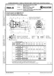
The magnetic drive rating at a nominal speed of 2900<br />
rpm is giv<strong>en</strong> in the pump data sheet.<br />
If the motor power exceeds this rating, it is necessary<br />
to check the stoppage of the magnetic drive.<br />
The same also applies if the required drive rating<br />
exceeds 80 % of the magnetic drive rating.<br />
Consult <strong>Richter</strong> if necessary.<br />
Differ<strong>en</strong>t operating data can be achieved without<br />
changing the pump through the use of differ<strong>en</strong>t<br />
speeds, e.g. by means of a frequ<strong>en</strong>cy converter.<br />
The pump with base plate and motor is illustrated in<br />
the installation drawing.<br />
The operating manual of the motor manufacturer<br />
must be observed.<br />
A motor with a valid ATEX certificate is to be<br />
used if employed in zone 1 and 2.<br />
5.8 Electric connection<br />
The operator is obligated to connect the assembly in<br />
accordance with existing regulations 8 (IEC, VDE,<br />
etc.).<br />
Allow only a trained electrician to perform the<br />
electrical connection.<br />
Compare the existing mains voltage with the<br />
indications on the motor’s manufacturer’s nameplate<br />
and choose a suitable circuit.<br />
A motor protection device (motor-circuit switch) is<br />
urg<strong>en</strong>tly recomm<strong>en</strong>ded.<br />
Danger of explosion if the electrical<br />
installation is incorrect.<br />
In areas at risk of explosion, IEC 60079-14<br />
must also be observed for the electrical<br />
installation.<br />
If the pump is mounted on a base plate, <strong>en</strong>suring<br />
electrical conduction through the use of a chopper<br />
disk or contact disk on the housing foot and support<br />
bracket.<br />
The assembly must be gro<strong>und</strong>ed in accordance with<br />
curr<strong>en</strong>tly effective regulations, for example, on the<br />
base plate.<br />
9240-050-<strong>en</strong> Revision 10<br />
TM 7813 Edition 03/2010
Series <strong>MPB</strong>, close-coupled design Page 14<br />
6 Commissioning / Shutdown<br />
6.1 Initial commissioning<br />
Normally, the pumps have already be<strong>en</strong> test-run with<br />
water. Unless special agreem<strong>en</strong>ts have be<strong>en</strong> made,<br />
there could still be residual amounts of water in the<br />
pump. This must be noted in view of a possible<br />
reaction with the medium.<br />
6.1.1 Filling the pump housing<br />
Check to see whether the screws on the suction<br />
flange, discharge flange, housing flange and drain<br />
flange are tight<strong>en</strong>ed. For screw tight<strong>en</strong>ing torques<br />
see Section 1.1.<br />
Op<strong>en</strong> the suction line fully so that the medium can<br />
flow into the pump.<br />
Op<strong>en</strong> the discharge valve so that the air in the<br />
pump can escape.<br />
If air cannot be v<strong>en</strong>ted into the discharge line, e.g.<br />
a drop in pressure in this line is not permitted,<br />
v<strong>en</strong>ting must be performed upstream of the<br />
discharge valve.<br />
Monitor the v<strong>en</strong>ting operation until no air but only<br />
liquid emerges.<br />
Close the discharge valve again until<br />
only the minimum flow rate is obtained<br />
after the motor has be<strong>en</strong> started.<br />
6.1.2 Start-up<br />
Check the direction of rotation of the motor with a<br />
rotary field instrum<strong>en</strong>t.<br />
As viewed from the motor, the direction of rotation<br />
of the pump is clockwise. See also the direction of<br />
rotation arrow of the pump.<br />
If no rotating field instrum<strong>en</strong>t is available, the<br />
motor may also be activated briefly, with the<br />
pump filled, so that it does run up. You can<br />
observe the direction of rotation through the fan hood.<br />
The pump must not run dry during the check<br />
of the direction of rotation.<br />
The pump must be completely filled with liquid. The<br />
maximum admissible flow rate must not be exceeded.<br />
Otherwise the plain bearings can run dry in<br />
both cases.<br />
Switch the motor on.<br />
Set the desired flow by op<strong>en</strong>ing the discharge<br />
valve.<br />
Wh<strong>en</strong> the motor is running but the pump is not<br />
conveying, this means that the magnetic drive<br />
has stopped.<br />
Switch motor off immediately in order to prev<strong>en</strong>t<br />
overheating of the magnet assemblies.<br />
Th<strong>en</strong> proceeded as follows:<br />
Close discharge valve down to the position<br />
"minimum flow rate".<br />
Start motor again.<br />
If the magnetic drive stops again, look for the cause.<br />
6.2 Operating limits<br />
The operating limits of the pump/unit in terms<br />
of pressure, temperature, power and speed<br />
are <strong>en</strong>tered in the data sheet and it is<br />
imperative to observe them!<br />
6.2.1 Min./max. flow rate<br />
The operating range g<strong>en</strong>erally recomm<strong>en</strong>ded<br />
lies at 0.3 Q opt to 1.1 Q opt . See for this Section<br />
2.6.2.<br />
6.3 Shutdown<br />
Close discharge valve down to the position<br />
"minimum flow rate"<br />
Switch motor off.<br />
Close discharge valve completely.<br />
Only close the suction line if the pump is to be<br />
evacuated or dismantled.<br />
For all work on the machine, make sure that<br />
the motor cannot be inadvert<strong>en</strong>tly switched<br />
on.<br />
If the pump is to be evacuated or flushed,<br />
observe the local regulations.<br />
If the pump has be<strong>en</strong> operated with a<br />
chargeable liquid, it must be filled with inert<br />
gas (e.g. nitrog<strong>en</strong>) to prev<strong>en</strong>t an explosive<br />
atmosphere.<br />
It is recomm<strong>en</strong>ded to wait one hour before the pump<br />
is dismantled from the plant to permit static peak<br />
charges to be eliminated.<br />
These measures are not necessary with pumps with a<br />
conductive plastic lining.<br />
If the pump is returned to the manufacturer's, clean<br />
the pump very thoroughly.<br />
See also Section 3.1.<br />
6.4 Restarting<br />
Wh<strong>en</strong> the pump is restarted, it must be <strong>en</strong>sured that<br />
all the relative steps as described in Section 6.1 are<br />
repeated, dep<strong>en</strong>ding on the progress of the shutdown<br />
operation.<br />
9240-050-<strong>en</strong> Revision 10<br />
TM 7813 Edition 03/2010
Series <strong>MPB</strong>, close-coupled design Page 15<br />
6.5 Improper operations and their<br />
consequ<strong>en</strong>ces (examples)<br />
Improper operation, ev<strong>en</strong> for a short time, can<br />
result in serious damage to the unit.<br />
In connection with explosion protection,<br />
pot<strong>en</strong>tial sources of ignition (overheating, electrostatic<br />
and induced charges, mechanical and electric sparks)<br />
may result from these improper operation; their<br />
occurr<strong>en</strong>ce can only be prev<strong>en</strong>ted by adhering to the<br />
int<strong>en</strong>ded use.<br />
Pump is started up without medium :<br />
♦ The plain bearings in the pump may be destroyed.<br />
♦ Other pump compon<strong>en</strong>ts may be destroyed due to<br />
overheating.<br />
Suction line not op<strong>en</strong>ed or not op<strong>en</strong>ed fully :<br />
♦ Pump is cavitating – material damage to pump<br />
and plain bearings<br />
♦ Pump does not attain the required delivery head<br />
or flow rate.<br />
♦ Pump may be destroyed due to overheating.<br />
Discharge valve closed too much:<br />
♦ Pump may be destroyed due to overheating.<br />
♦ Axial thrust too great.<br />
Discharge valve op<strong>en</strong>ed too much:<br />
♦ Pump can cavitate. Particularly severe with an<br />
empty discharge line.<br />
♦ Risk of pressure surge.<br />
♦ Possible damage to the plain bearings.<br />
♦ Magnetic drive may stop.<br />
♦ Motor may be overloaded.<br />
Suction valve and discharge valve closed:<br />
♦ Destruction due to rapid overheating and sharp<br />
rise in pressure.<br />
Control of the pump with the suction valve<br />
♦ Cavitation – the volume may only be regulated on<br />
the discharge side.<br />
Operation with magnetic drive stopped :<br />
♦ If no heat is dissipated, damage to the inner and<br />
drive magnet assemblies may occur.<br />
Overrun of the admissible gas cont<strong>en</strong>t:<br />
♦ The flow may stop.<br />
♦ Switch pump and v<strong>en</strong>t off for r<strong>en</strong>ewed<br />
conveyance.<br />
♦ Make sure that the gas cont<strong>en</strong>t is not exceeded, as<br />
described in the int<strong>en</strong>ded use.<br />
9240-050-<strong>en</strong> Revision 10<br />
TM 7813 Edition 03/2010
Series <strong>MPB</strong>, close-coupled design Page 16<br />
7 Maint<strong>en</strong>ance<br />
7.1 Screw connections of the<br />
housing<br />
After initial loading by the operating pressure and<br />
operating temperature the tight<strong>en</strong>ing torques of all<br />
connection screws must be checked at the following<br />
points:<br />
♦ cover flange<br />
♦ housing flange<br />
♦ suction flange<br />
♦ discharge flange<br />
♦ drain flange<br />
See also Section 6.1.1, para. 1.<br />
Other inspections are to be performed regularly,<br />
dep<strong>en</strong>ding on the operating requirem<strong>en</strong>ts.<br />
7.2 Motor<br />
The operating manual of the motor manufacturer must<br />
be observed.<br />
A motor with a valid ATEX certificate is to be<br />
used if employed in zone 1 and 2.<br />
Observe the ATEX notes of the motor manufacturer.<br />
7.3 Cleaning<br />
Care must be tak<strong>en</strong> wh<strong>en</strong> cleaning the pump to<br />
<strong>en</strong>sure that it is not exposed to a strong water jet.<br />
The ingress of water into the bearing pedestal will<br />
substantially impair bearing lubrication.<br />
7.4 Stand-by pumps<br />
If a pump is on stand-by, it is to be started up from<br />
time to time.<br />
This operation is to be performed more oft<strong>en</strong> for<br />
pumps which are exposed to very strong vibrations<br />
from the plant.<br />
Wh<strong>en</strong> dismantling the pump from the plant, drain it,<br />
thoroughly clean it, seal with flange covers and store<br />
in accordance with the instructions.<br />
7.5 Notes on dismantling<br />
♦ All repair and maint<strong>en</strong>ance work is to be performed<br />
by skilled staff using appropriate tools and original<br />
spare parts.<br />
♦ Is the necessary docum<strong>en</strong>tation available?<br />
♦ Has the pump be<strong>en</strong> tak<strong>en</strong> out of operation, drained<br />
and flushed correctly? See also Section 6.3.<br />
♦ If no new assembly is performed immediately after<br />
dismantling, the plastic and ceramic compon<strong>en</strong>ts in<br />
particular must be stored carefully.<br />
♦ <strong>Richter</strong> has the following special tools for<br />
dismantling in its range of delivery:<br />
♦ Clamping device Id<strong>en</strong>t. No. 9248-87-1091<br />
♦ Dismantling ring Id<strong>en</strong>t. No. 9247-89-8002<br />
For instructions on use, see Sections 10.2 and 10.3.<br />
7.5.1 Protective clothing<br />
Ev<strong>en</strong> if the pump has be<strong>en</strong> properly<br />
evacuated and flushed, residue of the<br />
medium may still remain in the pump, e.g.<br />
betwe<strong>en</strong> sealing surfaces or in the bearing seats or in<br />
the can or the can insert.<br />
Plastic compon<strong>en</strong>ts may absorb medium which<br />
gradually emerges from the material after flushing.<br />
Proper protective clothing is to be worn.<br />
Protective clothing is also to be worn ev<strong>en</strong> if only the<br />
bearing pedestal is to be removed. Medium may<br />
p<strong>en</strong>etrated the lantern chamber through the can.<br />
7.5.2 Magnetic fields<br />
Caution ! Strong magnetic fields<br />
Risk during dismantling and in the vicinity of<br />
magnetic drives as single parts.<br />
Remove loose parts and other magnetisable metals<br />
from the work b<strong>en</strong>ch. They could otherwise be<br />
attracted: Risk of accid<strong>en</strong>t!<br />
Place any tools needed at a safe distance.<br />
Keep electronic equipm<strong>en</strong>t and measuring<br />
instrum<strong>en</strong>ts at a distance. In cases of doubt consult<br />
the equipm<strong>en</strong>t manufacturer.<br />
Hold magnetic drives as single parts firmly or secure.<br />
Otherwise they could be attracted, for example, by a<br />
vice: Risk of accid<strong>en</strong>t!<br />
People with an artificial pacemaker<br />
Keep torso at a minimum distance of 500<br />
mm.<br />
For safety's sake, a distance of 150 mm should be<br />
observed for watches, electric data carriers, data<br />
carriers with magnetic strips etc.<br />
7.6 Dismantling<br />
Dismantling the complete pump from the plant.<br />
Undo screwing 901/4 and 554/5 from transition<br />
ring / lantern.<br />
Pull motor 800/1 with transition ring 820 and also<br />
hollow drive shaft 216 and drive magnet assembly<br />
858 out of the slide-in unit.<br />
9240-050-<strong>en</strong> Revision 10<br />
TM 7813 Edition 03/2010
Series <strong>MPB</strong>, close-coupled design Page 17<br />
Caution! Magnetic forces!<br />
Risk of accid<strong>en</strong>t !<br />
Axial forces are produced wh<strong>en</strong> the plain bearing<br />
pedestal is pulled out of the bearing pedestal. These<br />
forces diminish again abruptly after it has be<strong>en</strong><br />
removed.<br />
The operating torque of the magnetic coupling<br />
installed is specified on the type plate.<br />
Remove housing screws 901/3, 552/3.<br />
Remove lantern 344 with can insert 158/159 and<br />
intermediate ring 509/1.<br />
Remove cover screws 901/2, 552/1.<br />
Remove cover 160.<br />
Remove bearing nut 923. Right-hand thread.<br />
If necessary, hold inner magnet assembly tight<br />
with a strap wr<strong>en</strong>ch.<br />
Remove left-hand bearing sleeve 529/1.<br />
Remove left-hand bearing bush 545/1, if damaged.<br />
Mount clamping device on impeller shaft and<br />
<strong>en</strong>gage in the anti-torsion insert. Secure with<br />
screws to the housing (see drawing in Section<br />
10.2.<br />
Unscrew inner magnet assembly 859 using a strap<br />
wr<strong>en</strong>ch.<br />
Push out ring channels 241/1 and 241/2 as well as<br />
the single-piece impeller 230 with the dismantling<br />
ring. See drawing in section 10.3.<br />
The 3 c<strong>en</strong>tering gaskets 415/3 are also removed.<br />
Remove stud 560/1 from the housing.<br />
If necessary, remove O-ring 412/3 from the inner<br />
magnet assembly.<br />
Remove housing 100.<br />
Remove distance ring 504 and right-hand bearing<br />
sleeve 529/2 from the impeller shaft.<br />
Press right-hand bearing bush 545/2 out of the<br />
housing.<br />
7.6.1 Can, can insert and intermediate<br />
ring<br />
Loos<strong>en</strong> the c<strong>en</strong>tering of these compon<strong>en</strong>ts at the<br />
lateral recesses in the lantern 344.<br />
Pull the parts out of the lantern.<br />
Only separate the can 159 and can insert 158 if<br />
one part has to be replaced. If separation is not<br />
possible, the unit must be cooled to about 5°C.<br />
With a vacuum-tight design the can insert is glued to<br />
the can. Separation is not possible without causing<br />
damage.<br />
Dismantling is possible with a can with a leakage<br />
monitoring using a flexible p.c. board. However, reassembly<br />
should only be performed at the<br />
manufacturer's works.<br />
7.6.2 Dismantling of drive unit<br />
Undo setscrew 904/1.<br />
Separate hollow drive shaft 216 and drive magnet<br />
assembly 858 with hex. screws 901/5, lock<br />
washers 934/1.<br />
Pull hollow drive shaft 216 off motor shaft.<br />
Undo hex. screws 901/7 and washers 554/7 and<br />
transition ring 820 off the motor flange (possibly<br />
use two levers).<br />
Dismantling can be checked using the sectional<br />
drawing in Section 9.2 and 9.3 and the<br />
compon<strong>en</strong>ts available.<br />
7.7 Notes on assembly<br />
♦ Use original spare parts. See also Section 2.4.<br />
♦ Do not use any defective parts.<br />
♦ Has the pump be<strong>en</strong> shut down, drained and<br />
flushed in accordance with the regulations?<br />
See also Section 6.3.<br />
♦ Treat close-tolerance areas (not on stainless steel<br />
parts) with a corrosion inhibitor. Grease screw<br />
thread prior to assembly.<br />
♦ The thread in the impeller 230, the inner magnet<br />
assembly 859 and on the pump shaft 211 must not<br />
be greased as otherwise no optimum glued<br />
connection is possible.<br />
♦ Install plain bearings in pairs as supplied or stored.<br />
♦ Check whether all parts fit and only th<strong>en</strong> assemble.<br />
♦ Important dim<strong>en</strong>sions (c<strong>en</strong>terings, bearing fits or<br />
bearing play) are to be checked prior to assembly;<br />
perform a trial assembly if required.<br />
♦ Many metallic particles adhering to magnetic<br />
compon<strong>en</strong>ts such as the inner magnet assembly<br />
859 and drive magnet assembly 858 must be<br />
removed prior to assembly. For this purpose<br />
simple plastic<strong>en</strong>e can be used..<br />
♦ A complete assembly process is described in the<br />
following.<br />
Sub-sections can be deduced from this.<br />
♦ See also Section 7.5.<br />
7.8 Assembly<br />
7.8.1 Assembly of drive unit<br />
Screw transition ring 820 to the motor 800/1.<br />
Screw hollow drive shaft 216 and drive magnet<br />
assembly 859 together (901/5, 934/1).<br />
Push hollow drive shaft 216 fully onto motor shaft<br />
with key.<br />
Observe control dim<strong>en</strong>sion L, see drawing in<br />
Section 9.2 and 9.3 and pump works certificate.<br />
Drill the key of the motor shaft for setscrew 904/1.<br />
Screw on the setscrew 904/1 and secure with<br />
Loctite 243.<br />
9240-050-<strong>en</strong> Revision 10<br />
TM 7813 Edition 03/2010
Series <strong>MPB</strong>, close-coupled design Page 18<br />
7.8.2 Can, can insert and intermediate<br />
ring<br />
Install can insert in the can. If this is not possible,<br />
cool the can insert to about +5°C.<br />
Push intermediate ring 509/1 onto the can 159.<br />
Insert the <strong>en</strong>tire unit into the lantern 344.<br />
7.8.3 Housing, right-hand ring channel<br />
and right-hand bearing bush<br />
Press 3 c<strong>en</strong>tering gaskets 415/2 into the housing.<br />
The bore at the lowest point must not be sealed.<br />
Observe nozzle position and drain bore (at lowest<br />
point).<br />
Insert bearing bush 545/1 into the cover 160.<br />
Insert bearing bush 545/2 into the housing 100.<br />
Press stud 560/1 into the housing 100.<br />
Insert right-hand channel ring 241/2 into the<br />
housing 100.<br />
7.8.4 Assembly housing, impeller and<br />
inner magnet assembly<br />
Screw inner magnet assembly 859 with O-ring<br />
412/3 onto the impeller shaft 230. To tight<strong>en</strong> this<br />
unit, use a strap wr<strong>en</strong>ch and clamping device if<br />
possible (see Section 10.2). Insert ring channel<br />
241/1 into the housing 100.<br />
Mount bearing sleeve 529/1 onto the impeller shaft<br />
230. The anti-torsion cams must <strong>en</strong>gage in the<br />
grooves.<br />
Tight<strong>en</strong> bearing nut 923 hand-tight on the impeller<br />
shaft.<br />
Insert cover 160 with bearing bush 545/1 into the<br />
housing 100.<br />
Tight<strong>en</strong> cover screws 901/2 with tight<strong>en</strong>ing<br />
washers 552/1. For tight<strong>en</strong>ing torque, see Section<br />
1.1.<br />
Check whether the rotating unit can be turned by<br />
hand.<br />
Insert the can 159, can insert 158 and intermediate<br />
ring 509/1 into the lantern 344.<br />
♦ Observe magnetic forces.<br />
♦ Observe nozzle position.<br />
♦ The drain bore in the housing must be at the<br />
lowest position.<br />
Screw this unit to the previously assembled<br />
housing unit using the housing screws 901/3 and<br />
the tight<strong>en</strong>ing washers 552/3. For tight<strong>en</strong>ing<br />
torque, see Section 1.1.<br />
7.8.5 Drain (if provided)<br />
Insert c<strong>en</strong>tering gasket 415/1 into the drain bore of<br />
the cover.<br />
Place blind flange 122 on the c<strong>en</strong>tering gasket.<br />
Screw in studs 901/1 and tight<strong>en</strong> with washers<br />
554/1 and hex. nuts 920/1.<br />
For tight<strong>en</strong>ing torque, see Section 1.1.<br />
7.9 Tests<br />
Fig 7<br />
Mount bearing sleeve 529/2 and distance ring 504<br />
onto the impeller shaft 230 and push this unit<br />
through the bearing bush 545/2. The anti-torsion<br />
cams of the bearing sleeve must <strong>en</strong>gage in the<br />
grooves.<br />
Push pre-assembled housing onto the right-hand<br />
bearing sleeve 529/2.<br />
Apply 1 drop of adhesive to the shaft thread, e.g.<br />
Loctite 243 from the company Loctite, or an<br />
equival<strong>en</strong>t.<br />
Only 1 drop of the adhesive should be applied.<br />
Otherwise, the next dismantling operation will<br />
be more difficult or no longer possible without<br />
causing damage.<br />
The pumps are tested with water at the<br />
manufacturer's.<br />
The operating data measured are docum<strong>en</strong>ted in a<br />
works certificate.<br />
If, during a test after repairs, discrepancies compared<br />
with the works certificate are discovered, the following<br />
people can be called in:<br />
1) In-house pump office<br />
2) The manufacturer <strong>Richter</strong><br />
or its local ag<strong>en</strong>t<br />
The following conveying data can be checked using<br />
the pump performance curves :<br />
♦ Flow rate<br />
♦ Head<br />
♦ Power requirem<strong>en</strong>t<br />
♦ NPSHR<br />
9240-050-<strong>en</strong> Revision 10<br />
TM 7813 Edition 03/2010
Series <strong>MPB</strong>, close-coupled design Page 19<br />
8 Faults<br />
Faults may result from improper operation.<br />
Such improper operation – ev<strong>en</strong> brief ones –<br />
may cause serious damage to the unit.<br />
In connection with explosion protection, pot<strong>en</strong>tial<br />
sources of ignition (overheating, electrostatic and<br />
induced charges, mechanical and electric sparks) can<br />
result from these improper operation; their occurr<strong>en</strong>ce<br />
can only be prev<strong>en</strong>ted by adhering to the int<strong>en</strong>ded<br />
use.<br />
Should there be any uncertainty about the remedy to<br />
be applied, please inquire at the in-house pump office<br />
or at the pump manufacturer's.<br />
No delivery :<br />
♦ Is the pump filled and v<strong>en</strong>ted?<br />
♦ Is the suction line op<strong>en</strong>, v<strong>en</strong>ted, cleaned and<br />
correctly laid?<br />
♦ Is the discharge line op<strong>en</strong>, v<strong>en</strong>ted, cleaned and<br />
correctly laid?<br />
♦ Is the geodetic head too high?<br />
♦ Is air being drawn in?<br />
♦ Has the magnetic drive stopped?<br />
Flow rate too high :<br />
♦ Is the geodetic head too low?<br />
♦ Are the pipe or nozzle resistances too low?<br />
♦ Is the pump speed too high or the impeller<br />
diameter too large?<br />
Delivery pressure too high :<br />
♦ Is the speed too high or the impeller diameter<br />
too large?<br />
♦ Is the d<strong>en</strong>sity too high?<br />
Motor consumes too much electricity :<br />
♦ Is the flow rate, d<strong>en</strong>sity or viscosity too high?<br />
♦ Is the speed too high or the impeller diameter too<br />
large?<br />
♦ Can the pump shaft be turned properly?<br />
Pump does not run smoothly or creates<br />
noises :<br />
♦ Are the rolling bearings of the motor damaged?<br />
♦ Are parts of the hydraulics damaged?<br />
♦ Is the flow rate too low or too high?<br />
♦ Is the impeller balanced?<br />
♦ Is the pump twisted?<br />
♦ Is there foreign matter in the pump?<br />
Leak from the pump :<br />
♦ Are all screws tight<strong>en</strong>ed to the correct tight<strong>en</strong>ing<br />
torque?<br />
♦ Were the sealing surfaces assembled in a clean<br />
state?<br />
♦ Have approved gaskets be<strong>en</strong> installed?<br />
Delivery pressure too high :<br />
♦ Is the speed too high or the impeller diameter too<br />
large?<br />
♦ Is the d<strong>en</strong>sity too high?<br />
Flow rate too low :<br />
♦ Have the pump, suction line and discharge line<br />
be<strong>en</strong> completely v<strong>en</strong>ted, filled and cleaned?<br />
♦ Have any strainers installed be<strong>en</strong> cleaned?<br />
♦ Are all shut-off devices op<strong>en</strong>?<br />
♦ Is the geodetic head too high?<br />
♦ Is the NPSHA too low or the NPSHR too high?<br />
♦ Are the pipe resistances too high?<br />
♦ Is the viscosity too high?<br />
♦ Is the direction of rotation correct?<br />
♦ Is the speed too low or the impeller diameter too<br />
small?<br />
♦ Are pump parts worn?<br />
♦ Gas in the medium?<br />
9240-050-<strong>en</strong> Revision 10<br />
TM 7813 Edition 03/2010
Series <strong>MPB</strong>, close-coupled design Page 20<br />
9 Sectional drawing<br />
9.1 Leg<strong>en</strong>d sectional drawing<br />
100 housing<br />
122 blind cover<br />
158 can insert<br />
159 can<br />
160 cover<br />
216 hollow drive shaft<br />
235 impeller shaft<br />
241/x ring channel<br />
344 lantern<br />
412/3 o-ring<br />
415/x c<strong>en</strong>tering gasket<br />
504 distance ring<br />
509/1 intermediate ring<br />
529/x bearing sleeve<br />
545/x bearing bush<br />
552/x tight<strong>en</strong>ing washer<br />
554/x washer<br />
557/1 contact disc<br />
560/1 stud<br />
592 support (upwards and IEC motor size 132)<br />
800/1 motor<br />
820 transition ring<br />
(disp<strong>en</strong>sed with IEC motor sizes 100 + 112)<br />
858 drive magnet assembly<br />
859 inner magnet assembly<br />
900/1 ring bolt<br />
901/x hex. screw<br />
902/1 stud screw<br />
904/1 setscrew<br />
914/2 hex. socket screw<br />
920/1 hex. nut<br />
923 bearing nut<br />
934/1 lock washer<br />
936/2 toothed lock washer<br />
9240-050-<strong>en</strong> Revision 10<br />
TM 7813 Edition 03/2010
Series <strong>MPB</strong>, close-coupled design Page 21<br />
9.2 Sectional drawing <strong>MPB</strong>, housing in L-position<br />
Clearances X, Y and Z see pump work's certificate<br />
* Base required for IEC motor sizes 132 and upwards<br />
** Transition ring disp<strong>en</strong>sed with IEC motor sizes 100 and 112<br />
Drill key for motor shaft during assembly.<br />
Secure setscrew 904/1 with Loctite 243.<br />
9240-050-<strong>en</strong> Revision 10<br />
TM 7813 Edition 03/2010
Series <strong>MPB</strong>, close-coupled design Page 22<br />
9.3 Sectional drawing <strong>MPB</strong>, housing in V-position<br />
Clearances X, Y and Z see pump work's certificate<br />
* Base required for IEC motor sizes 132 and upwards<br />
** Transition ring disp<strong>en</strong>sed with IEC motor sizes 100 and 112<br />
Drill key for motor shaft during assembly.<br />
Secure setscrew 904/1 with Loctite 243.<br />
9240-050-<strong>en</strong> Revision 10<br />
TM 7813 Edition 03/2010
Series <strong>MPB</strong>, close-coupled design Page 23<br />
10 Assembly aids<br />
10.1 Boring template<br />
Pump size<br />
Id<strong>en</strong>t.-No<br />
<strong>MPB</strong> 25-25-115 9217-89-1094<br />
10.2 Assembly/Dismantling aid for inner magnet assembly<br />
9240-050-<strong>en</strong> Revision 10<br />
TM 7813 Edition 03/2010
Series <strong>MPB</strong>, close-coupled design Page 24<br />
10.3 Dismantling ring<br />
9240-050-<strong>en</strong> Revision 10<br />
TM 7813 Edition 03/2010
Modification techniques possibles sans réservées!<br />
Graphique non à l'échelle!<br />
Dim<strong>en</strong>sions valables uniquem<strong>en</strong>t revêtues d'une signature!<br />
This leaflet is subject to alteration!<br />
Drawing not to scale!<br />
Certified for construction purposes only wh<strong>en</strong> signed!<br />
Technische Änderung<strong>en</strong> vorbehalt<strong>en</strong>!<br />
Nicht maßstäblich!<br />
Maße nur mit Unterschrift verbindlich!<br />
CHEMIENORMPUMPEN / CHEMICAL PROCESS PUMPS / POMPE POUR L'INDUSTRIE CHIMIQUE<br />
Baureihe/Series/Série Ausführung Peripheralpumpe<br />
<strong>MPB</strong><br />
Design<br />
Peripheral pump<br />
Construction Pompe périphériques<br />
Einsatzgr<strong>en</strong>z<strong>en</strong> / operating limits<br />
1 Standard<br />
Bei Einsatz unter ASME-Bedingung<strong>en</strong><br />
(Sphäroguss nach A395) kann der<br />
Standardbereich auf -30 °C <strong>und</strong> 16 bar<br />
erweitert werd<strong>en</strong>.<br />
Standard<br />
Application <strong>und</strong>er ASME-specification<br />
(ductile iron acc. to A395)<br />
the standard range can be expanded<br />
up to -30 °C and 16 bar.<br />
3 Tiefere Temperatur<strong>en</strong> durch Sondermaterial Lower temperatures by special materials<br />
4 Höheres Vakuum bei Pump<strong>en</strong>stillstand durch<br />
Sonderspalttöpfe<br />
Higher vacuum at pump standstill by special<br />
can unit<br />
9240-00-3030/4-00 © <strong>Richter</strong> Chemie-Technik GmbH<br />
- 1 -
<strong>Richter</strong> Chemie-Technik GmbH<br />
Otto-Schott-Straße 2<br />
D-47906 Kemp<strong>en</strong><br />
www.richter-ct.com<br />
A Unit of IDEX Corporation<br />
Konformitätserklärung nach EN ISO//IEC 17050<br />
Declaration of Conformity according to EN ISO//IEC 17050<br />
Produkt<br />
Product<br />
Baureihe<br />
Series<br />
EU-Richtlini<strong>en</strong><br />
EU-Directive<br />
Modul<br />
Magnetkupplungs-Chemiekreiselpumpe<br />
freies Well<strong>en</strong><strong>en</strong>de, Blockausführung oder als Aggregat 1)<br />
Magnetic Drive Chemical C<strong>en</strong>trifugal Pump<br />
Bare shaft, block version or as unit 1)<br />
MNK, MNK-B, MNK-X, MNK-XB, MNK-S, MNK-SB, MNKA, MNKA-B<br />
<strong>MPB</strong>, MDK, MDK-B, RMA, RMA-B, RMI, RMI-B<br />
2006/42/EG Maschin<strong>en</strong>richtlinie Machinery Directive<br />
94/9/EG Explosionsschutzrichtlinie ATEX Equipm<strong>en</strong>t explosive atmosphere<br />
Interne Fertigungskontrolle<br />
Production Quality Assurance<br />
Angewandte EN 14121<br />
harmonisierte Norm<strong>en</strong> EN 809<br />
Applied harmonised EN 13463-1<br />
Standards<br />
K<strong>en</strong>nzeichnung<br />
2006/42/EG<br />
Marking 94/9/EG II 2 GD IIC TX X 1)<br />
Die technische Dokum<strong>en</strong>tation nach Richtlinie 94/9EG ist bei der u.a. b<strong>en</strong>annt<strong>en</strong> Stelle hinterlegt.<br />
The technical docum<strong>en</strong>tation is filed by below m<strong>en</strong>tioned notified body according to directive 94/9/EC.<br />
Physikalische-Technische B<strong>und</strong>esanstalt (PTB), D-38116 Braunschweig<br />
Baureihe<br />
Series<br />
Registrier-Nr.<br />
Registered #<br />
Baureihe<br />
Series<br />
Registrier-Nr.<br />
Registered #<br />
Baureihe<br />
Series<br />
Registrier-Nr.<br />
Registered #<br />
MNK 02ATEXD032 MNKA 04ATEXD007 RMA 09ATEXD062<br />
MNK-B 03ATEXD006 MNKA-B RMA-B 09ATEXD062<br />
MNK-X 02ATEXD032 <strong>MPB</strong> 03ATEXD068 RMI<br />
MNKXB 03ATEXD006 MDK 02ATEXD009 RMI-B<br />
MNK-S 02ATEXD032 MDK-B 03ATEXD008<br />
MNK-SB 03ATEXD006<br />
Das Unternehm<strong>en</strong> <strong>Richter</strong> Chemie-Technik GmbH bescheinigt hiermit, dass die o.a. Baureih<strong>en</strong> die gr<strong>und</strong>sätzlich<strong>en</strong><br />
Anforderung<strong>en</strong> der aufgeführt<strong>en</strong> Richtlini<strong>en</strong> <strong>und</strong> Norm<strong>en</strong> erfüllt.<br />
<strong>Richter</strong> Chemie-Technik GmbH confirms that the basic requirem<strong>en</strong>ts of the above specified directives and standards<br />
have be<strong>en</strong> fulfilled.<br />
Bevollmächtigt für die Zusamm<strong>en</strong>stellung der technisch<strong>en</strong> Unterlag<strong>en</strong> nach 2006/42/EG:<br />
Authorised person compiled the technical files according to 2006/42/EG:<br />
A. Linges<br />
1) Gilt nicht für das Aggregat nach 94/9/EG (ATEX Leitfad<strong>en</strong> Juni 2009 Abschn. 3.7.5 2.a)<br />
1) Not valid for the unit according to 94/9/EG (ATEX Guideline June 2009 Paragraph 3.7.5 2.a)<br />
Kemp<strong>en</strong>, 01.03.2010<br />
________________________________<br />
_________________________________<br />
G. Kleining A. Linges<br />
Leiter Forschung & Entwicklung<br />
Leiter Qualitätsmanagem<strong>en</strong>t<br />
Manager Research & Developm<strong>en</strong>t<br />
Quality Manager<br />
Erstellt/Compiled: CRM/GK am/on: 01.03.2010 Seite/Page : 1 QM-Nr.: 0905-40-1036/4-01-de<br />
G<strong>en</strong>ehmigt/Approved: CRQ/AL am/on: 01.03.2010 von/of : 1
<strong>Richter</strong> Chemie-Technik GmbH<br />
Otto-Schott-Straße 2<br />
D-47906 Kemp<strong>en</strong><br />
www.richter-ct.com<br />
A Unit of IDEX Corporation<br />
Konformitätserklärung nach EN ISO//IEC 17050<br />
Declaration of Conformity according to EN ISO//IEC 17050<br />
Produkt<br />
Product<br />
Magnetkupplungs-Chemiekreiselpumpe<br />
als Aggregat<br />
Magnetic Drive Chemical C<strong>en</strong>trifugal Pump<br />
as unit<br />
Baureihe<br />
Series<br />
MNK, MNK-B, MNK-X, MNK-XB, MNK-S, MNK-SB, MNKA, MNKA-B<br />
<strong>MPB</strong>, MDK, MDK-B, RMA, RMA-B, RMI, RMI-B<br />
EU-Richtlini<strong>en</strong><br />
EU-Directive<br />
2006/42/EG Maschin<strong>en</strong>richtlinie<br />
Machinery Directive<br />
Modul<br />
Interne Fertigungskontrolle<br />
Production Quality Assurance<br />
Angewandte EN 14121<br />
harmonisierte Norm<strong>en</strong> EN 809<br />
Applied harmonised<br />
Standards<br />
K<strong>en</strong>nzeichnung<br />
Marking<br />
2006/42/EG<br />
Das Unternehm<strong>en</strong> <strong>Richter</strong> Chemie-Technik GmbH bescheinigt hiermit, dass die o.a. Baureih<strong>en</strong> die<br />
gr<strong>und</strong>sätzlich<strong>en</strong> Anforderung<strong>en</strong> der aufgeführt<strong>en</strong> Richtlini<strong>en</strong> <strong>und</strong> Norm<strong>en</strong> erfüllt.<br />
<strong>Richter</strong> Chemie-Technik GmbH confirms that the basic requirem<strong>en</strong>ts of the above specified directives and<br />
standards have be<strong>en</strong> fulfilled.<br />
Bevollmächtigt für die Zusamm<strong>en</strong>stellung der technisch<strong>en</strong> Unterlag<strong>en</strong> nach 2006/42/EG:<br />
Authorised person compiled the technical files according to 2006/42/EG:<br />
A. Linges<br />
Kemp<strong>en</strong>, 01.07.2010<br />
________________________________<br />
_________________________________<br />
G. Kleining A. Linges<br />
Leiter Forschung & Entwicklung<br />
Leiter Qualitätsmanagem<strong>en</strong>t<br />
Manager Research & Developm<strong>en</strong>t<br />
Quality Manager<br />
Erstellt/Compiled: CRM/GK am/on: 01.07.2010 Seite/Page : 1 QM-Nr.: 0905-40-1041/4-00-de<br />
G<strong>en</strong>ehmigt/Approved: CRQ/AL am/on: 01.07.2010 von/of : 1
Safety Information / Declaration of No Objection Concerning the Contamination<br />
of <strong>Richter</strong>-<strong>Pumps</strong>, -Valves and Compon<strong>en</strong>ts<br />
1 SCOPE AND PURPOSE<br />
Each <strong>en</strong>trepr<strong>en</strong>eur (operator) carries the responsibility for the health and safety of his<br />
employees. This ext<strong>en</strong>ds also to the personnel, who implem<strong>en</strong>ts repairs with the operator or<br />
with the contractor.<br />
Enclosed declaration is for the information of the contractor concerning the possible<br />
contamination of the pumps, valves and compon<strong>en</strong>t s<strong>en</strong>t in for repair. On the basis of this<br />
information for the contractor is it possible to meet the necessary prev<strong>en</strong>tive action during the<br />
execution of the repair.<br />
Note: The same regulations apply to repairs on-site.<br />
2 PREPARATION OF DISPATCH<br />
Before the dispatch of the aggregates the operator must fill in the following declaration<br />
completely and attach it to the shipping docum<strong>en</strong>ts. The shipping instructions indicated in the<br />
respective manual are to be considered, for example:<br />
• Discharge of operational liquids<br />
• remove filter inserts<br />
• lock all op<strong>en</strong>ings hermetically<br />
• proper packing<br />
• Dispatch in suitable transport container<br />
• Declaration of the contamination fixed outside!! on the packing<br />
Prepared: CRQ/Lam on: Feb. 15, 06 Page: 1 QM No.: 0912-16-2001_<strong>en</strong>/4-06<br />
Approved: CRQ/Zu on: Feb. 15, 06 of : 2
Declaration about the Contamination of<br />
<strong>Richter</strong> <strong>Pumps</strong>, -Valves<br />
and Compon<strong>en</strong>ts<br />
The repair and/or maint<strong>en</strong>ance of pumps, valves and compon<strong>en</strong>ts can only be implem<strong>en</strong>ted if a completely filled out<br />
declaration is available. If this is not the case, delay of the work will occur. If this declaration is not attached to the<br />
devices, which have to be repaired, the transmission can be rejected.<br />
Every aggregate has to have it’s own declaration.<br />
This declaration may be filled out and signed only by authorized technical personnel of the operator.<br />
Contractor/dep./institute : Reason for transmitting Please mark the applicable<br />
Repair: subject to fee Warranty<br />
Street : Exchange: subject to fee Warranty<br />
Postcode, city:<br />
Exchange/ Replacem<strong>en</strong>t already initiated/received<br />
Contact person: Return: Leasing Loan for credit note<br />
Phone : Fax :<br />
End user :<br />
A. Details of <strong>Richter</strong>-product: Failure description:<br />
Classification:<br />
Article number:<br />
Equipm<strong>en</strong>t:<br />
Serial number:<br />
Application tool:<br />
Application process:<br />
B. Condition of the <strong>Richter</strong>-product: no 1) yes no Contamination : no 1) yes<br />
Was it in operation ? toxic <br />
Drained (product/operating supply item) ? caustic <br />
All op<strong>en</strong>ings hermetically locked! inflammable <br />
Cleaned ? explosive 2) <br />
If yes, with which cleaning ag<strong>en</strong>t: mikrobiological 2) <br />
and with which cleaning method: radioactive 3)<br />
1) if "no", th<strong>en</strong> forward to D. other pollutant <br />
2) Aggregates, which are contaminated with microbiological or explosive substances, are only<br />
accepted with docum<strong>en</strong>ted evid<strong>en</strong>ce of an approved cleaning.<br />
3)<br />
Aggregates, which are contaminated with radioactive substances, are not accepted in principle.<br />
C. Details of the discharged materials (must be filled out imperatively)<br />
1. With which materials did the aggregate come into contact ? Trade name and/or chemical<br />
designation of operational f<strong>und</strong>s and discharged materials, material properties, e.g. as per<br />
safety data sheet (e.g. toxic, inflammable, caustic)<br />
X Trade name: Chemical designation:<br />
a)<br />
b)<br />
c)<br />
d)<br />
no yes<br />
2. Are the materials specified above harmful to health ? <br />
3. Dangerous decomposition products during thermal load ? <br />
If yes, which ones ?<br />
D. Mandatory declaration: We assure that the data in this explanation are truthful and complete and as a signatory I am<br />
able to form an opinion about this. We are aware that we are responsible towards the contractor for damages, which results<br />
from incomplete and incorrect data. We commit ourselves to exempt the contractor from claims for damages of thirds<br />
resulting from incomplete or incorrect data. We are aware that we are directly responsible towards thirds, irrespective of this<br />
declaration, which belongs in particularly to the employees of the contractor consigned with the handling repair of the product.<br />
Name of the authorized person<br />
(in block letters):<br />
Date Signature Company stamp<br />
Prepared: CRQ/Lam on: Feb. 15, 06 Page: 2 QM No.: 0912-16-2001_<strong>en</strong>/4-06<br />
Approved: CRQ/Zu on: Feb. 15, 06 of : 2
FAX<br />
Fax No. ()<br />
Pages (incl. cover sheet) ()<br />
To:<br />
()<br />
Contact person: Refer<strong>en</strong>ce: Ext<strong>en</strong>sion: E-Mail Address: Date:<br />
() () - () () ()<br />
Your order No.: ()<br />
Our Kom. No.: () Serial No.: ()<br />
Dear Sirs,<br />
The compliance with laws for the industrial safety obligates all commercial <strong>en</strong>terprises to protect their<br />
employees and/or humans and <strong>en</strong>vironm<strong>en</strong>t against harmful effects while handling dangerous<br />
materials.<br />
The laws are such as: the Health and Safety at Work Act (ArbStättV), the Ordinance on Harzadous<br />
Substances (GefStoffV, BIOSTOFFV), the procedures for the prev<strong>en</strong>tion of accid<strong>en</strong>ts as well as<br />
regulations to <strong>en</strong>vironm<strong>en</strong>tal protection, e.g. the Waste Managem<strong>en</strong>t Law (AbfG) and the Water<br />
Resources Act (WHG)<br />
An inspection/repair of <strong>Richter</strong> products and parts will only take place, if the attached explanation is<br />
filled out correctly and completely by authorized and qualified technical personnel and is available.<br />
In principle, radioactively loaded devices s<strong>en</strong>t in, are not accepted.<br />
Despite careful draining and cleaning of the devices, safety precautions should be necessary<br />
however, the ess<strong>en</strong>tial information must be giv<strong>en</strong>.<br />
The <strong>en</strong>closed declaration of no objection is part of the inspection/repair order. Ev<strong>en</strong> if this certificate is<br />
available, we reserve the right to reject the acceptance of this order for other reasons.<br />
Best regards<br />
RICHTER CHEMIE-TECHNIK GMBH<br />
Enclosures<br />
()<br />
Landesbank Rheinland-Pfalz, Mainz Kto. 110 145810 (BLZ 550 500 00)<br />
SWIFT: MALA DE 555 50 USt. Id. Nr. DE 811 127054<br />
Sitz der Gesellschaft: Kemp<strong>en</strong> Amtsgericht Krefeld HRB 9635 Geschäftsführer: Dipl.-Ing. Günter Naasner<br />
QM-Nr.: 0912-16-2001an_<strong>en</strong>/4-01