Chemical Process Pump - Richter Pumps
Chemical Process Pump - Richter Pumps
Chemical Process Pump - Richter Pumps

You also want an ePaper? Increase the reach of your titles
YUMPU automatically turns print PDFs into web optimized ePapers that Google loves.
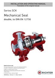
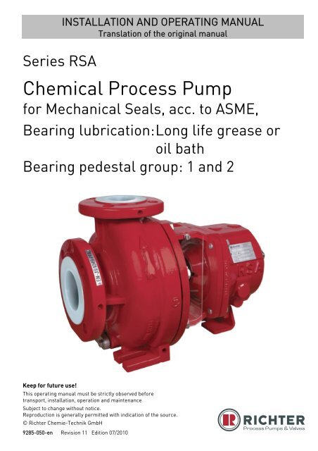
Series RSAINSTALLATION AND OPERATING MANUALTranslation of the original manual<strong>Chemical</strong> <strong>Process</strong> <strong>Pump</strong>for Mechanical Seals, acc. to ASME,Bearing lubrication: Long life grease oroil bathBearing pedestal group: 1 and 2Keep for future use!This operating manual must be strictly observed beforetransport, installation, operation and maintenanceSubject to change without notice.Reproduction is generally permitted with indication of the source.© <strong>Richter</strong> Chemie-Technik GmbH9285-050-en Revision 11 Edition 07/2010
Series RSA Page 2List of ContentsList of Contents ........................................ 2Relevant documents ................................. 31 Technical data ...................................... 31.1 Tightening torques ....................................... 41.2 Type plate, ATEX and housing markings .... 41.3 Spareparts ................................................... 42 Safety .................................................... 52.1 Intended use ................................................ 52.2 Notes on safety for the customer / operator 62.3 Notes on safety for maintenance ................ 62.4 Conversion work and production of spareparts by the customer .................................. 62.5 Improper operation ...................................... 62.6 Special requirements for explosion protection................................................................. 62.6.1 Filling the unit ................................................... 62.6.2 Special operating conditions ............................ 72.6.3 Chargeable liquids ........................................... 72.6.4 Identification ..................................................... 72.6.5 Check of the direction of rotation ..................... 72.6.6 Mode of operation of the pump ........................ 72.6.7 Temperature limits ........................................... 82.6.8 Maintenance ..................................................... 82.6.9 Electric peripheral equipment ........................... 83 Transport, storage and disposal ........ 93.1 Return consignments .................................. 93.2 Disposal ....................................................... 94 Product description ........................... 105 Installation .......................................... 105.1 Safety regulations ...................................... 105.2 Installation of pump/unit ............................ 105.3 Alignment of pump-coupling-motor ........... 105.4 Piping......................................................... 115.4.1 Nominal size ................................................... 115.4.2 Nozzle loads ................................................... 115.4.3 Suction line ..................................................... 115.4.4 Supply lines .................................................... 115.4.5 Discharge line ................................................ 115.4.6 Venting and evacuating .................................. 125.5 Pipe fittings ................................................ 125.6 Monitoring facilities .................................... 125.7 Drive .......................................................... 125.8 Coupling .................................................... 135.9 Final check ................................................ 135.10 Coupling guard .......................................... 135.11 Electric connection .................................... 136 Commissioning/Shutdown ................ 146.1 Initial commissioning ................................. 146.1.1 Mechanical seals ............................................ 146.1.2 Filling the pump housing ................................ 146.1.3 Start-up ........................................................... 146.2 Operating limits ......................................... 146.2.1 Abrasive media............................................... 146.2.2 Min./max. flow rate ......................................... 146.3 Shutdown .................................................. 156.5 Improper operations and their consequences(examples) ................................................ 157 Maintenance ....................................... 167.1 Safety-relevant screw fittings .................... 167.2 Bearing pedestal ....................................... 167.2.1 Grease for life lubrication ............................... 167.2.2 Oil bath lubrication.......................................... 167.3 Cleaning .................................................... 177.4 Stand-by pumps ........................................ 177.5 Notes on dismantling ................................ 177.5.1 Protective clothing .......................................... 177.6 Dismantling ............................................... 177.6.1 Remove slide-in unit. ...................................... 177.6.2 Dismantling of bracket chamber ..................... 177.6.3 Dismantling the bearing pedestal long-life greaselubrication ....................................................... 187.6.4 Dismantling the bearing pedestal oil bathlubrication ....................................................... 187.7 Notes on assembly ................................... 187.8 Assembly ................................................... 187.8.1 Assembly bearing pedestal ............................ 187.8.2 Assembly bracket chamber ............................ 187.8.3 Final assembly ............................................... 187.8.4 Fill bearing pedestal with oil ........................... 197.9 Tests ......................................................... 198 Malfunctions ....................................... 209 Sectional drawing .............................. 219.1 Legend ..................................................... 219.2 RSA long life grease lubrication ............... 229.3 RSA oil bath lubrication ............................ 2310 Assembly aids .................................... 2410.1 Impeller wrench for open impeller ............. 2410.2 Clamping device for SCK single mechanicalseals .......................................................... 249285-050-en Revision 11TM 7903 Edition 07/2010
Series RSA Page 3Relevant documents♦ Data sheet♦ Works certificate♦ Sectional drawing:RSA long life grease lubrication 9285-00-3000RSA oil bath lubrication 9285-00-3001External single mechanical seal 9285-00-3021Double mechanical seal 9285-00-3020♦ Installation and operating manual for mechanicalseals:External single mechanical seal,Double mechanical seal9285-060-en♦ Installation drawing 9285-00-3017♦ Dimensional drawing 9285-00-3015♦ Performance curves♦ Spare parts list♦ Operating manual and declaration of conformitymotor *♦ Operating manual and declaration of conformitycoupling *Appendix to the operating manual♦ Operational limits 9285-00-3030♦ Declaration of conformity with ATEX♦ Declaration of conformity without ATEX♦ Form for Safety Information Concerning theContamination QM 0912-16-2001_enOn request:♦ Publication: "Centrifugal <strong>Pump</strong> Operation withoutNSPH Problems"♦ Publication "Safe Operation of Magnetic Drive<strong>Pump</strong>s“* if contained in the scope of delivery1 Technical dataManufacturer :<strong>Richter</strong> Chemie-Technik GmbHOtto-Schott-Str. 2D-47906 KempenTelephone: +49 (0) 2152 146-0Fax: +49 (0) 2152 146-190E-Mail: richter-info@idexcorp.comInternet: http://www.richter-ct.com<strong>Richter</strong> EP (Nanjing) Co., LTd.No. 18 Ailing Rd., Moling,Jiangning Dev. Zone211111 NanjingP.R. ChinaTelephone: +86 (0) 25 / 5275 1718Fax: +86 (0) 25 / 5275 1747E-Mail: jyin@idexcorp.comInternet: http://www.richter-ct.comAuthorised person acc. to machine directive2006/42/EG: Gregor KleiningDesignation :Single-stage, plastic-lined, chemical centrifugal pumpfor mechanical seals, series RSA, long life grease oroil bath lubricationHorizontal designTechnical specifications ASME B73.1, ASME B73/3M,ISO 15783, ISO 5199 and HI standardsConnecting dimensions to ASME B73.1Flange connecting dimensions:ASME B16.5 Class 150ATEX 95 Directive 94/9/ECMachine Directive 2006/42/EC9285-050-en Revision 11TM 7903 Edition 07/2010Materials :Pressure-bearing parts:Ductile cast iron ASTM A 395 / EN-JS 1049 / stainlesssteelWetted parts:PFA, PTFE, Al 2 O 3 , FFKMand see data sheet.Flow rate : up to 570 Usgpm (130m 3 /h)(at 3500 rpm)Delivery head : up to 330 ft (100m) (at 3500 rpm)Housing discharge pressure :max. 275psi (19bar)Temperature range :Operating conditions to standardASME–20 °F (–29 °C) up to302 °F (150 °C)ISO–30 °C (–22 °F) up to150 °C (302 °F)Temperature classes as per ATEX :see Section 2.6.7.Admissible ambient conditions for pumpsacc. to directive 94/9/ EG (ATEX 95) :Ambient temperature range: 4 °F bis 104 °F,– 20 °C bis + 40 °C (higher temperature afterconsulting the manufacturer)Ambient pressure range: 11,6 psia – 16 psia0,8 bar abs – 1,1 bar absNoise capacity level : L WA = ≤ 70 dB acc. toDIN EN ISO 9614-2
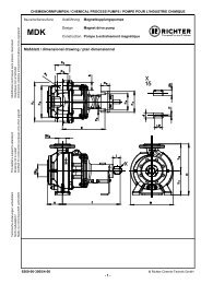
Series RSA Page 4Sizes :Group 1 Group 21,5"x1"x6"3"x2"x8"3"x2"x6"1,5"x1"x8"Weight : See data sheetDimensions : See installation drawing1.2 Type plate, ATEX and housingmarkingsThe stainless steel type plate is undetachably rivetedto the housing.If the operator attaches his identification, it must beensured that the pump matches the application inquestion.Example of type plate:1.1 Tightening torquesScrews greased, tighten in diametrically oppositesequence.Housing screws 901/3Size No. x size Tightening torque[inch] [ASME] [in-lbs] [Nm]1,5"x1"x6" 8 x ½“ 415 473"x2"x6" 8 x ½“ 415 471,5"x1"x8" 10 x ½“ 390 443"x2"x8" 12 x ½“ 415 47ATEX marking:Pipe screws, flanges to ASME B16.5 Class 150DN No. x size Tightening torque[inch] [ASME] [in-lbs] [Nm]1“ 4 x ½“ 70 81½“ 4 x ½“ 135 152“ 4 x 5/8“ 220 253“ 4 x 5/8“ 400 45Housing identification:The following are visible on the housing according toDIN EN 19:♦ Nominal size♦ Rated pressure♦ Housing material♦ Manufacturer's identification♦ Melt number/Foundry identification♦ Cast date1.3 SparepartsSpare parts for two years of continuous operation inaccordance with DIN 24296 and in consultation withthe manufacturer9285-050-en Revision 11TM 7903 Edition 07/2010
Series RSA Page 52 SafetyThis operating manual contains fundamentalinformation which is to be observed during installation,operation and maintenance.It must be read before installation andcommissioning!This operating manual must always be available at theplace of use of the machine/plant.Observe the safety notes in all the chapters.Installation, operation and maintenance are to beperformed by qualified staff.The area of responsibility, authority and supervision ofthe staff must be exactly regulated by the customer.If the staff do not have the necessary expertise, theyare to be trained and instructed.If necessary, this can be provided by themanufacturer/supplier on behalf of the machineoperator.General hazard symbol! People may be putat risk.Safety symbol! The pump and its functionmay be put at risk if this safety symbol is notobserved.EU marking! Explosion-protectedequipment must be identified for work inpotentially explosive areas.Warning of electric power!It is imperative to observe signs attached directly tothe pump / unit, e.g.:♦ Direction of rotation arrow♦ CE markingand they are to be kept legible.Non-observance of the notes on safety may resultin the loss of any and all claims for damages.Non-observance may involve the following hazards :♦ Failure of important functions of the machine/plant.♦ Risk to people from electric, mechanical andchemical effects.♦ Risks to the environment through leaks ofhazardous substances.2.1 Intended use♦ <strong>Richter</strong> pumps of the series RSA are plastic-linedcentrifugal pumps for the leak-free conveyance ofaggressive, toxic, pure and inflammable liquids.♦ Vertical installation of the pumps is only possiblewith pumps with long life grease-lubricated rollingbearings. In this type of installation the mechanicalseal must be designed as a liquid-sealed versionor a seal with quench. Please consult themanufacturer.The observance of the specified physical limits isimportant for perfect functioning and safe operation,especially with regard to explosion protection toprevent potential sources of ignition (see Section2.6):♦ Make sure that the mechanical seal is alwayslubricated with liquid.♦ For safe pump operation, we recommend a flowrate which lies between 0.3 and 1.1 Q opt . Themaximum operating temperature must never beexceeded. See Section 2.6.7. In case of doubt,you must consult the manufacturer.♦ The manufacturer must be consulted in the eventof entrainment of gas >2% as well as solids inorder to avoid a lack of lubrication and dry-running.♦ The plant NPSH value (NPSHA) should be 0.5 mhigher than the NPSH value of the pump(NPSHR). See also Section 5.4.1.Improper operation, even for brief periods,may result in serious damage to the unit.In connection with explosion protection, potentialsources of ignition (overheating, electrostatic andinduced charges, mechanical and electric sparks) canresult from these inadmissible modes of operation;their occurrence can only be prevented by adhering tothe intended use.Furthermore, reference is made in this connection tothe Directive 95/C332/06 (ATEX 118a) which containsthe minimum regulations for improving theoccupational health and safety of the workers whomay be at risk from an explosive atmosphere.Do not operate the unit above the valuesspecified in the data sheet for the♦ fluid♦ flow rate♦ speed♦ density♦ head♦ operating temperature and♦ motor ratingObserve the instructions contained in theoperating manual or contractual documentation; ifnecessary, consult the manufacturer.All important features are documented in the datasheet included in the scope of delivery.In the event of operating conditions other than thosedescribed in the data sheet, the following are to bechecked again:♦ design of the pump♦ design of the accessories♦ resistance of the materials.9285-050-en Revision 11TM 7903 Edition 07/2010
Series RSA Page 72.6.2 Special operating conditionsThe pump is normally used to convey aggressive andinflammable liquids.For safe pump operation, we recommend a flow rateof 0.3 to 1.1 Q opt . If the pump is operated outside thisrange, it must be ensured that the max. admissibleflow rate according to the pump characteristic curve isnot exceeded and that the max. admissible operatingtemperature according to Section 2.6.7 is observed.If the flow rate is too high, there is a risk that thepressure in the area of the mechanical seal falls untilthe vapour pressure of the fluid is undershot. As aresult, this may lead to dry-running, particularly withthe single mechanical seals, involving inadmissibleoverheating and the destruction of the mechanicalseal.If the flow rate is too low, the medium may heat up somuch owing to the fluid friction that the max.admissible surface temperature of the relevanttemperature class is exceeded.Overloading, overheating or non-observance of thedesign data can result in inadmissible modes ofoperation and it is therefore imperative to avoid them.The situation is to be remedied by providingappropriate monitoring facilities. See Section 5.6.The plant NPSH value (NPSHA) should be 0.5 mhigher than the NPSH value of the pump (NPSHR toprevent damage to the pump).2.6.3 Chargeable liquidsFor operation with chargeable liquids with aconductivity
Series RSA Page 82.6.7 Temperature limitsIn the normal operating condition the highesttemperatures are to be expected at thecontact point shaft seal/shaft, on the innerraces of the ball bearings and, at high mediumtemperatures, on the surface of the pump housing.In the case of liquids >40 °C (>104 °F) the surfacetemperature of the pump housing is generally lowerthan the temperature of the liquid as the plastic lininghas an insulating effect.If the pump is heated (e.g. heating jacket), itmust be ensured that the temperatureclasses prescribed in the annex areobserved.The non heated pump surface must have free contactwith the environment.When operating the pump, make sure that anexcessive deposit of dust is avoided(possibly regular cleaning). This prevents thepump surface from heating to above the admissibletemperature.The table below indicates the admissible mediumtemperature, depending on the pump design, as afunction of the temperature class in accordance withEN 13463-1.Temperature classacc. to EN 13463-1T685 °C (185 °F)T5100 °C (212 °F)T4135 °C (275 °F)T3200 °C (392 °F)T2300 °C (572 °F)T1450 °C (842 °F)Limit value of thetemperature of the liquidnot certified to ATEX130 °C (266 °F)150 °C (302 °F)150 °C (302 °F)150 °C (302 °F)1) 2)The plant customer must ensure that theprescribed operating temperature is observed.The maximum admissible temperature of theliquid medium at the pump inlet depends on thetemperature class and the selected lining materialrequired in each case.2.6.8 MaintenanceTo achieve safe and reliable operation, it mustbe ensured in inspections at regular intervalsthat the unit is properly serviced and kept intechnically perfect order.Example: Functioning of the rolling bearings. Themode of operation and operating conditions largelydetermine the actual service life that can be attained.Regular checks of the bearing pedestal area canprevent excessive temperatures due to hot-runningrolling bearings, or even defective bearing seals. SeeSection 7.2.In regard to media containing solids, the maintenanceintervals must be set by the operator in accordancewith the conditions of operation.If auxiliary systems (e.g. cooling, heating) areinstalled, check to see whether monitoring facilitiesare required to ensure their function.2.6.9 Electric peripheral equipmentElectric peripheral equipment, e.g. pressure,temperature and flow sensors etc. mustcomply with the prevailing safety requirementsand explosion protection provisions.Note : If the operating manual of the mechanical sealdemands a lower medium temperature than indicated inthe above table, this lower medium temperature isdecisive.1) Long life grease lubrication : no restriction.Oil bath lubrication : standard design with shaft seal T32) Consult the manufacturer for higher limit values.If different temperature classes (e.g. pump T4,mechanical seal T3) arise when one medium is usedfor pumps and the mechanical seal, the lowertemperature class (in the above example T3) appliesto the entire pump including the mechanical seal.Observance of the temperature class T4 with oil bathlubrication is not possible with the standard shaft seal.9285-050-en Revision 11TM 7903 Edition 07/2010
Series RSA Page 93 Transport, storage and disposalThe pump or the unit must be transportedproperly. It must be ensured that duringtransport the pump/unit remains in thehorizontal position and does not slip out of thetransport suspension points.A pump or motor can be suspended from the ring boltprovided for this purpose.The suspension points are not suitable fortransporting a complete unit, i.e. pump with baseplate and motor.In this case, the slinging points for the ropes on thebase plate are to be used. See Fig. 1.The slinging ropes must not be attached to free shaftends or to the ring bolt of the motor.3.1 Return consignments<strong>Pump</strong>s which have conveyed aggressive ortoxic media must be well flushed andcleaned before being returned to themanufacturer's works.It is imperative to enclose a safety informationsheet / general safety certificate on the field ofapplication with the return consignment.Pre-printed forms are enclosed with the installationand operating manual.Safety precautions and decontamination measuresare to be mentioned.3.2 DisposalParts of the pump may be contaminated with mediumwhich is detrimental to health and the environmentand therefore cleaning is not sufficient.Risk of personal injury and damage to theenvironment due to the medium or oil!Fig. 1Directly after receipt of the goods, theconsignment must be checked for completenessand any in-transit damage.Damaged pumps must not be installed in the plant.Handle goods carefully to prevent damage.Flange covers serve as protection during transportand must not be removed.If the unit is not installed immediately after delivery, itmust be put into proper storage.The product should be stored in a dry and vibrationfree,well ventilated room at as constant atemperature as possible.Elastomers are to be protected against UV light.In general, a storage period of 10 years should not beexceeded. An admissible storage period of 4 yearsapplies to elastomers made of NBR.In the case of prolonged storage conservation agentson machined component surfaces and packing with adesiccant may be necessary.♦ Wear protective clothing when work is performedon the pump.♦ Prior to the disposal of the pump: Collect any medium, oil etc. which hasescaped and dispose of it in accordance withthe local regulations. Neutralise any medium residues in the pump.♦ Separate pump materials (plastics, metals etc.)and dispose of them in accordance with the localregulations.9285-050-en Revision 11TM 7903 Edition 07/2010
Series RSA Page 104 Product descriptionThe housing dimensions, nominal ratings andtechnical requirements of the pump series RSAcorrespond to ASME B73.1, ISO 15783, ISO 5199.The technical requirements of the VDMA 24279 aresatisfied.The sectional drawings show the design of the pump.See Section 9.All components which come into contact with themedium are either plastic-lined or made of otherresistant materials, e.g. Al 2 O 3 , FFKM.The housing 100 and the bracket 344 consist of ametallic shell and are lined or coated with plastic inthe wetted area.Together with the impeller 230, these 3 componentsform the hydraulic part of the pump.The high-strength pump shaft 210 made of specialsteel is protected against corrosion in the wetted areaby a shaft sleeve 524. It is sealed against the impellerby means of an axially pressed O-ring 412/1 made ofFFKM.The shaft sleeve 524 has a positive connection withthe shaft 210 and the shoulder ring 505 by means ofthe parallel pins 562/1 and is therefore securedagainst turning.The static tightness of the pump is guaranteed bythe screw fitting of the bracket 344 and the housing100. The housing gasket 401 is clamped betweenboth components with the required sealing force.Long-life grease lubrication:The rolling bearing system comprises two greasefilledradial ball bearings 321/1 and 321/2 withsealing on both sides.Oil bath lubrication:The rolling bearing system comprises two radial ballbearings 321/1 and 321/2, which are supplied withlubricant by an oil bath.The oil bath is sealed against the atmosphere by tworadial shaft seals 421/1, 421/2 and an O-ring 412/2.The bracket chamber is designed so that both singleand double mechanical seals can be used.Further design details are provided in the encloseddrawing. Additional information are provided in thebrochure and the product manual.5 Installation5.1 Safety regulationsEquipment which is operated in potentiallyexplosive areas must satisfy the explosionprotection regulations.People with a pacemaker are at risk from thestrong magnetic field of the magnetic drive. Itmay be life-threatening for them to stay at adistance of less than 20” (500 mm) to the pump.5.2 Installation of pump/unitThe structural work must be prepared in accordancewith the dimensions in the installation drawing.Method of installation:on a grouted base plate and firm foundation. Align base plate on the ground foundation. Insert foundation bolts and grout base plate. Do not tighten the foundation bolts uniformly andfirmly until the mortar has set.Other possibilities of installing the pump are:♦ 4-point installation♦ 4-point installation with base plate.As soon as additional installations aremounted, the stability of the entire unitinstalled without a foundation must bechecked.5.3 Alignment of pump-couplingmotorThe following information is of a generalnature. If necessary, special notes of thecoupling and motor manufacturer are to beobserved.After attachment of the base plate on thefoundation and connection of the pipes, thealignment of the coupling must be carefullychecked and, if necessary, the unit re-aligned withthe motor. A coupling check and possible re-alignment isalso necessary if the pump and motor aresupplied on a common base plate and aligned. Prior to alignment undo the support bracket 183and then tighten it without stress. The pump is to be aligned in all directions using aspirit level (on shaft/discharge nozzle)(admissible position deviation max. 0.08” in/ft(0,2 mm/m). A distance depending on the coupling used is tobe observed between the pump and motor shafts.See installation drawing. Use supports in the direct vicinity of the boltsfoundation/base plate.Ensure that the unit cannot be startedduring work without the coupling guard.9285-050-en Revision 11TM 7903 Edition 07/2010
Series RSA Page 115.4 PipingBefore the pump is installed, both, the suction andsupply lines as well as the discharge line are to becleaned.Dirt or damage to the sealing surfaces is best avoidedif the flange covers remain on the flanges until justbefore installation.Use flange gaskets suitable for the medium.The screw tightening torques in Section 1.1 are to beobserved for tightening the flange screws.5.4.1 Nominal sizeThe operating design point of a centrifugal pump liesat the intersection of the pump curve and the pipecurve, see Fig. 2. The pump curve is provided by thepump manufacturer. The pipe curve is determinedusing diagrams or PC programs.5.4.2 Nozzle loadsThe pump can be subjected to nozzle loads inaccordance with ANSI/HI 9.6.2.Changes in the length of the piping caused bytemperature are to be allowed for by appropriatemeasures, e.g. the installation of expansion joints.5.4.3 Suction lineThe suction lines must always be laid on a risinggradient towards the pump. Otherwise, gas bubblesmay form which considerably reduce the suction linecross section. Eccentric transition elements must beinstalled between different pipe diameters.Valves which disrupt the course of flow should notbe installed directly upstream of the pump.Fig. 35.4.4 Supply linesFig. 2Under no circumstances can the nominal size of thepiping be derived from the connected nominal size ofthe pump.The pipe nominal size can also be determined usingthe flow rate as a rough guide.v (ft / s)Q (gpm)=2449 x A (ft )v (m / s)3Q (m / s)=2A (m )The velocity in the suction line should not exceed6.56 ft/s (2 m/s) and 16.4 ft/s (5 m/s) in the dischargeline.When determining the suction line nominal size, theNPSH value (net positive suction head) must also beobserved. The NPSHR value required for the pump isspecified in the data sheet.The NPSHR available in the plantshould be at least 1.64 ft (0,5 m)higher than the NPSHR required forthe pump. Otherwise, this will lead to a drop in thedelivery head, cavitation or even failure of the pump.Supply lines should vent towards the reservoir andare therefore to be laid with a constant downwardgradient towards the pump.Should the piping internals upstream of the pump behorizontal, a low point can, of course, be locatedupstream of these internals.From here the pipe is then laid with an upwardgradient to the pump so that the gas bubbles whichform here can escape through the pump.Valves which disrupt the course of flow should notbe installed directly upstream of the pump.5.4.5 Discharge lineDo not arrange the shut-off valve directly above thepump but initially provide a transition section.The discharge nozzle velocity of the medium can – ifnecessary – be reduced.9285-050-en Revision 11TM 7903 Edition 07/2010
Series RSA Page 125.4.6 Venting and evacuatingVenting can take place into the discharge line orupstream of the discharge valve.A venting line can also be used as a bypass, drain orflushing line.The pump housing is fitted with a drain connection asa standard feature. Optionally, the drain bore can bedrilled.See Fig. 4.Fig. 45.6 Monitoring facilitiesAppropriate monitoring facilities are to berecommended, depending on therequirements placed on operational safetyand availability of the unit.<strong>Richter</strong> provides information on request and cansupply:♦ Flow meters♦ Filling level indicators♦ Motor load monitorsYou can obtain the publications "Safe Operation ofMagnetic Drive <strong>Pump</strong>s" and "The Operation ofCentrifugal <strong>Pump</strong>s without NPSH Problems" onrequest.5.5 Pipe fittingsThe following pipe fittings are available from <strong>Richter</strong>on request:♦ Shut-off valves♦ Check valves♦ Sight glasses♦ Priming vessels♦ Strainers♦ Pressure gauges5.7 DriveThe power consumption of the pump at theoperating design point is specified in the data sheetand works certificate.If the operating design point was not known whenthe pump was dispatched, the power consumptioncan be read off the appropriate performance curves.The max. density, the max. viscosity, powerallowances for the relevant mechanical seal and asafety margin are to be taken into account.Different operating data can be achieved withoutchanging the pump through the use of differentspeeds, e.g. by means of a frequency converter.The pump with base plate and motor is illustrated inthe installation drawing.Observe the operating manual of the motormanufacturer.A motor with a valid ATEX certificate is to beused if employed in zone 1 and 2.Fig. 59285-050-en Revision 11TM 7903 Edition 07/2010
Series RSA Page 135.8 CouplingIf one coupling half engages with the other, the clawsection is normally to be mounted on the drive shaftand the coupling half with the smooth end face on themotor shaft.Observe the operating manual of the couplingmanufacturer.A coupling with a valid ATEX certificate is tobe used if deployed in zone 1 and 2.Regulations exist, e.g. for the following details:♦ Arrangement of the coupling halves♦ Max. bore diameter♦ Max. transmitted power♦ Spacing of the coupling halves♦ Maximum values for offset and angularmisalignment.Should the pump housing and motor remain on thebase plate for repair work, a spacer type coupling isrequired.5.9 Final checkCheck the alignment of the coupling again inaccordance with Section 5.3.It must be possible to easily turn the unit at thecoupling by hand.5.10 Coupling guardThe pump may only be operated with a couplingguard in accordance with the accident preventionregulations.It must be ensured that the coupling guardused is either made of spark-free material orthe impact test required by the EN 13463 issatisfied without any reservations.<strong>Richter</strong> offers both versions.The operator must ensure that, after the couplingprotection has been mounted, the requirements ofthe machine guideline are fulfilled.5.11 Electric connectionThe operator is obligated to connect the assembly inaccordance with existing regulations 8 (IEC, VDE,etc.).Allow only a trained electrician to performthe electrical connection.Compare the existing mains voltage with theindications on the motor’s manufacturer’s nameplateand choose a suitable circuit.A motor protection device (motor-circuit switch) isurgently recommended.Danger of explosion if the electricalinstallation is incorrect.In areas at risk of explosion, IEC 60079-14must also be observed for the electricalinstallation.If the pump is mounted on a base plate, ensuringelectrical conduction through the use of a chopperdisk or contact disk on the housing foot and supportbracket.The assembly must be grounded in accordance withcurrently effective regulations, for example, on thebase plate.9285-050-en Revision 11TM 7903 Edition 07/2010
Series RSA Page 146 Commissioning/Shutdown6.1 Initial commissioningNormally, the pumps have already been test-run withwater.Unless special agreements have been reached, theremay still be some residual amounts of water in thepump. This must be noted in view of a possiblereaction with the medium.Long life grease lubricationThe ball bearings are greased for life. Regreasingis not possible and not necessary.For service lives, see Section 7.2.Oil bath lubrication:Pour in oil into the bearing pedestal!For procedure and the oil grade, see Sections 7.2and 7.8.5.6.1.1 Mechanical sealsThe design and material combination are specified inthe data sheet.The proper condition of the components andthe protective facilities must be ensured toprevent any risk from escaping medium.Before the pump is filled, quench and liquid-sealingdevices of the mechanical seal are to be put intooperation in accordance with the regulations of therelevant mechanical seal manufacturer.The regulations and recommendations of themechanical seal manufacturer must always beobserved.See relevant installation and operating manual for themechanical seal.6.1.2 Filling the pump housing Check to see whether the screws on the suctionflange, discharge flange, housing flange and drainflange are tightened. When retightening thehousing screws, make sure that the supportbracket is undone. Otherwise, the pump could bedeformed.For screw tightening torques see Section 1.1. Open the suction line fully so that the medium canflow into the pump. Open the discharge valve so that the air in thepump can escape. If air cannot be vented into the discharge line, e.g.a drop in pressure in this line is not permitted,venting must be performed upstream of thedischarge valve. Monitor the venting operation until no air but onlyliquid emerges. Turn the pump shaft at the coupling several times. Monitor the venting operation again until no moreair emerges. Close the discharge valve again untilonly the minimum flow rate is obtainedafter the motor has been started.6.1.3 Start-up Check the direction of rotation of the motor withthe coupling disengaged or with a rotary fieldinstrument. As viewed from the motor, the direction ofrotation of the pump is clockwise. See also thedirection of rotation arrow of the pump.The pump must not run dry during the checkof the direction of rotation. Check alignment of the coupling. Mount coupling guard.The pump must be completely filled withliquid.The maximum admissible flow rate must notbe exceeded.There is a risk that single mechanical sealswould run dry in both operating modes. Switch the motor on. Set the desired flow by opening the dischargevalve.6.2 Operating limitsThe operating limits of the pump/unit interms of pressure, temperature, power andspeed are entered in the data sheet and it isimperative to observe them!6.2.1 Abrasive mediaIf liquids with abrasive constituents areconveyed, increased wear at the pump is tobe expected. The inspection intervals shouldbe reduced compared with the usual times.6.2.2 Min./max. flow rateThe operating range generally recommended lies at0.3 Q opt to 1.1 Q opt . Consult the manufacturer foroperation outside this range and observe Section2.6.2.9285-050-en Revision 11TM 7903 Edition 07/2010
Series RSA Page 156.3 Shutdown Close discharge valve down to the position"minimum flow rate" Switch motor off. Close discharge valve completely.Only close the suction line if the pump is to beevacuated or dismantled.For all work on the machine, make sure thatthe motor cannot be inadvertently switchedon.If the pump is to be evacuated or flushed,observe the local regulations.If the pump has been operated with achargeable liquid, it must be filled with inertgas (e.g. nitrogen) to prevent an explosiveatmosphere.If the pump is to be dismantled, quench or liquidsealingdevices of the mechanical seal are to be shutdown in accordance with the regulations of therelevant mechanical seal manufacturer.It is recommended to wait one hour before the pumpis dismantled from the plant to permit static peakcharges to be eliminated.If the pump is returned to the manufacturer's, cleanthe pump very thoroughly.See also Section 3.1.6.4 Improper operations and theirconsequences (examples)Improper operation, even for brief periods,may result in serious damage to the unit.In connection with explosion protection,potential sources of ignition (overheating, electrostaticand induced charges, mechanical and electric sparks)can result from these inadmissible modes ofoperation; their occurrence can only be prevented byadhering to the intended use.<strong>Pump</strong> is started up without medium :♦ The plain bearing in the pump may be destroyed.♦ Other pump components may be destroyed due tooverheating.Suction line not opened or not opened fully :♦ <strong>Pump</strong> is cavitating – material damage to pump andplain bearings♦ <strong>Pump</strong> does not attain the required delivery head orflow rate.♦ <strong>Pump</strong> may be destroyed due to overheating.Discharge valve opened too much :♦ <strong>Pump</strong> may be destroyed due to overheating.Axial thrust too great.Discharge valve closed too much :♦ <strong>Pump</strong> can cavitate. Particularly severe with anempty discharge line.♦ Risk of pressure surge.♦ Possible damage to the plain bearings.♦ Magnetic drive may stop.♦ Motor may be overloaded.Suction valve and discharge valve closed :♦ Destruction due to rapid overheating and sharprise in pressure.Control of the pump with the suction valve :♦ Cavitation – the volume may only be regulated onthe discharge side. Cavitation – the volume mayonly be regulated on the discharge side.Overrun of the admissible gas content:♦ The flow may stop.♦ Switch pump and vent off for renewedconveyance.♦ Make sure that the gas content is not exceeded,as described in the intended use.<strong>Pump</strong>s with quench or pressurisationsystem :<strong>Pump</strong> is started up without quench orpressurisation system :♦ The mechanical seal on the atmosphere side isalready destroyed after a few revolutions.<strong>Pump</strong> is started up with too low a sealingliquid pressure :♦ The process medium can enter the liquid sealsystem and destroy the metallic parts of themechanical seal.Too high pressure of the quench medium :♦ The wetted O-ring can be pressed into theprocess medium.Sealing liquid consumption too high :♦ Is the pump not running smoothly?♦ Can a leak be seen on the mechanical sealhousing?♦ Does the leak come from a static sealing point?♦ Or from a sliding surface on the atmosphereside?♦ Or from connection points of the supply ordischarge lines?♦ If no exterior leak is visible, the missing sealingliquid enters the product. Repair the wettedmechanical seal.9285-050-en Revision 11TM 7903 Edition 07/2010
Series RSA Page 167 Maintenance7.1 Safety-relevant screw fittingsAfter initial loading by the operating pressure andoperating temperature the tightening torques of allconnection screws must be checked at the followingpoints:♦ casing (housing) - lantern♦ suction flange♦ discharge flange♦ draining flange♦ seal housing – bracket with double mechanicalseals♦ screw connections of the thermosiphon systemwith double mechanical seals.See also Section 6.1.1, para. 1.Other inspections are to be performed regularly,depending on the operating requirements.7.2 Bearing pedestalThe temperature of the bearing pedestal isnot to exceed more than 122 °F (50 °C) andunder no circumstances 176 °F (80 °C).If higher temperatures do occur, call in qualified staffwithout delay. If this is not possible, the pump must beshut down and taken out of service.In many cases a vibration measurement isrecommended to detect bearing wear in good time.7.2.1 Grease for life lubricationGrease fill bearings of the series 2RS are installed asstandard features. The grease is lithium-saponified.The admissible temperature range is – 22 °F to230 °F (– 30 °C to + 110 °C).The rolling bearings are designed for an L 10 servicelife of > 17,500 hours. The service life of the greasefilling guaranteed by the bearing manufacturers isgiven in the following table.7.2.2 Oil bath lubricationWe recommend a mineral oil with the followingcharacteristics for an expected bearing temperatureof about 158 °F (70 °C):Viscosity index : approx. 85Kinematic viscosity at 104 °F (40 °C) :appr .240 mmsA fully synthetic gear oil to ISO VG 220 is to be usedfor temperatures below – 68 °F (– 20 °C).Replacing the bearings: The ball bearings aredesigned for an L 10 service life of >17,500 hours.We recommend 17.500 working hours respectivelyevery 3 years a change of bearing should be made.Oil changes: 1x per year at bearing temperaturesof about 122 °F (50 °C).Every 6 months at bearing temperatures of about158 °F (70 °C).At higher temperatures more frequently inaccordance with the regulations.When the pump is serviced, it is recommended toreplace the bearings and shaft seals as a precautionand to pour in fresh oil.Oil level check: The oil level is to be regularlychecked on the constant level oiler 638/1 to ensuresafe operation.It must be ensured that there is always oil in theconstant level oiler; it must under no circumstancesbe completely drained.In potentially explosive works it isadvisable to monitor the condition ofthe ball bearingsIf there is a suspicion that splash water could haveentered the bearing pedestal, the oil must bereplaced immediately. Even small amounts of waterin the oil reduce the service life of the ball bearingsto a fraction of the normal service life.SizeGroup 1Group 2Bearing size > Service life6207-2RS / 15000 hr*6210-2RS / 15000 hr** at bearing temperature < 122 °F (50 °C)at bearing temperature 158 °F (70 °C) approx. 7500 hrIf the pump is serviced, it is recommended to alsoreplace the bearings as a precaution.In potentially explosive works it isadvisable to monitor the condition ofthe rolling bearings.9285-050-en Revision 11TM 7903 Edition 07/2010
Series RSA Page 177.3 CleaningCare must be taken when cleaning the pump toensure that it is not exposed to a strong water jet.The ingress of water into the bearing pedestal willsubstantially impair ball bearing lubrication.7.4 Stand-by pumpsIf a pump is on stand-by, it is to be started up fromtime to time. Regularly turn the shaft by hand in thedirection of rotation.This operation is to be performed more often forpumps which are exposed to very strong vibrationsfrom the plant.When dismantling the pump from the plant, drain it,thoroughly clean it, seal with flange covers and storein accordance with the instructions.7.5 Notes on dismantling♦ All repair and maintenance work is to beperformed by skilled staff using appropriate toolsand original spare parts.♦ Is the necessary documentation available?♦ Has the pump been shut down, drained andflushed in accordance with the regulations?See also Section 6.3.♦ If no new assembly is performed immediately afterdismantling, the plastic and ceramic componentsin particular must be stored carefully.♦ Dismantling can be checked using the sectionaldrawings in Section 9 and the componentsavailable.7.6 DismantlingThere are two possibilities for dismantling:1. Dismantling the complete pump from the plant.2. Dismantling the complete slide-in unit as thepump housing can remain in the plant connectedto the piping.If the coupling installed is a spacer-type coupling,the motor can also remain in the plant.Dismantling of the complete pump is described here. Undo support bracket 183 from the base plate. Disconnect sealing liquid pressure or quenchlines from the pump by undoing the screw fittings917/1 and 917/2 (see Installation and OperatingManual Mechanical Seal 9285-060-en).If the housing 100 remains in the plant, leave thehousing gasket 401 in the centering to protect thehousing sealing surface.7.6.1 Remove slide-in unit. Deposit pump vertically on the workbench withthe suction nozzle facing downwards. For thispurpose, use a soft, clean and smooth base. Undo screws 901/3 from the connectionhousing/lantern. Disconnect the slide-in unit from the centering ofthe housing 100. Use the forcing thread in thebracket flange provided for this purpose. After disconnection, the unit can be raised with acrane. A thread is provided in the drive shaft foraccommodating a crane lug. Deposit slide-in unit and then clamp it in a vice sothat the shaft is secured and the impeller is freelyaccessible from the top.7.5.1 Protective clothingEven if the pump has been properlyevacuated and flushed, residue of themedium may still remain in the pump, e.g.between sealing surfaces or in the bearing seats or inthe can.Plastic components may absorb medium whichgradually emerges from the material after flushing.Proper protective clothing is to be worn.7.6.2 Dismantling of bracket chamber Unscrew the impeller 230 from the shaft 210using a strap wrench or special impeller wrench(see Assembly aids in Section 10). As a result,the O-ring 412/1 and shaft sleeve 523/1 areremoved. Undo hex. screws 901/10 of the connectionbearing pedestal/bracket. Remove bracket 344 from the centering of thebearing pedestal 330. The forcing thread in thebearing pedestal flange can be used for thispurpose. For dismantling the mechanical seal, refer to therelevant Installation and Operating Manual 9285-060-en.9285-050-en Revision 11TM 7903 Edition 07/2010
Series RSA Page 187.6.3 Dismantling the bearing pedestallong-life grease lubrication Remove bearing pedestal unit from the vice anddeposit horizontally on the workbench. Undo hex. socket screws 914/6 and remove therear bearing cover 361 from the bearing pedestal330. Pull or push the shaft 210 including rollingbearings out of the bearing pedestal 330. Remove circlips 932/1 and 932/2 from the shaft210. Remove rolling bearings 321/1 and 321/2 from theshaft 210 using a pulling-off device.7.6.4 Dismantling the bearing pedestaloil bath lubrication Remove bearing pedestal unit from the vice anddeposit horizontally on the workbench. Undo hex. socket screws 914/6 and remove therear bearing cover 361 including the O-ring 412/2and rotary shaft seal 421/1 from the bearingpedestal 330. Pull or push shaft 210 including rolling bearingsout of the bearing pedestal 330. Remove circlips 932/1 and 932/2 from the shaft210. Remove rolling bearings 321/1 and 321/2 from theshaft 210 using a pulling-off device. To change the rotary shaft seals 421/1 and 421/2,press them out of the rear bearing cover 361 or thebearing pedestal 330.7.7 Notes on assembly♦ Use original spare parts. See also Section 2.4.♦ Do not use defective parts.♦ Has the pump been shut down, drained andflushed in accordance with the regulations?See also Section 6.3.♦ Apply Anti-Seize special assembly paste (e.g. fromWeicon) to the fitting surfaces (not any stainlesssteel surfaces) and screw thread prior toassembly.♦ Check whether all parts fit and only thenassemble.♦ Important dimensions (centerings, bearing fits orbearing play) are to be checked prior to assembly;perform a trial assembly if required.♦ We recommend that the housing gasket 401 andthe shaft sleeves 523/1, 523/2, 523/3 be replacedduring every new assembly.9285-050-en Revision 11TM 7903 Edition 07/20107.8 AssemblyA complete assembly process is described in thefollowing.Sub-sections can be deduced from this. See alsoSection 7.5.7.8.1 Assembly bearing pedestalOil bath lubrication Insert rotary shaft seals 421/1 and 421/2 into therelevant fittings of the rear bearing cover 361 orbearing pedestal 330. Insert O-ring 412/2 into the groove of the rearbearing cover 362.Long-life grease and oil bath lubrication Press rolling bearings 321/1 and 321/2 onto theshaft 210.Caution!Different rolling bearing sizes! Mount circlips 932/1 and 932/2. Push complete drive shaft into the bearingpedestal 330. Mount rear bearing cover and tighten hex. socketscrews 914/6.Tightening torque group 1 = 150 in-lbs (17Nm)Tightening torque group 2 = 177 in-lbs (20Nm) Clamp complete bearing pedestal with thecoupling side of the shaft 210 in a vice.7.8.2 Assembly bracket chamber For installation of the mechanical seal, refer tothe relevant Installation and Operating Manual9285-060-en. Insert shaft sleeve 523/1 and O-ring 412/1 intothe impeller 230. Screw impeller unit onto the shaft 230 and tightenwith a strap wrench or special impeller wrench(see Section 10).7.8.3 Final assembly Deposit the housing 100 on a workbench, forexample, with the suction nozzle facingdownwards. Protect the plastic working stripagainst damage with a suitable support. Insert housing gasket 401 into the centering ofthe housing 100. Carefully insert pre-assembled slide-in unit intothe centering of the housing. Alternatively, the unit can be mounted using acrane. For this purpose, a thread is provided inthe drive shaft to accommodate a crane lug. Tighten screws 901/3 in diametrically oppositesequence.
Series RSA Page 197.8.4 Fill bearing pedestal with oilOil quantities:For group 1 appr. 14 oz (400 ml)For group 2 appr. 52 oz (1540 ml)Groups see Section 1.Type of oil:See Section 7.2.2.Procedure for filling with oil: Tilt constant level oiler 638/1. Fill the oiler with oil. Swing the constant level oiler into the verticalposition. If the oil level still falls too much, pour more oil intothe oiler.7.9 TestsOn request, the pumps are tested with water at themanufacturer's.The operating data measured are then documentedin a works test certificate.If, during a test after repairs, discrepanciescompared with the works certificate are discovered,the following people can be called in:1. in-house pump office2. The manufacturer <strong>Richter</strong>or its local agentThe following conveying data can be checked usingthe pump performance curves:♦ Flow rate♦ Head♦ Power requirement♦ NPSHRFig. 69285-050-en Revision 11TM 7903 Edition 07/2010
Series RSA Page 208 MalfunctionsFaults may result from inadmissible modes ofoperation. Improper operation, even for briefperiods, may result in serious damage to theunit.In connection with explosion protection, potentialsources of ignition (overheating, electrostatic andinduced charges, mechanical and electric sparks) canresult from these inadmissible modes of operation;their occurrence can only be prevented by adhering tothe intended use.See also Section 6.5.Should there be any uncertainty about the remedy tobe applied, please inquire at the in-house pump officeor at the pump manufacturer's.No delivery :♦ Is the pump filled and vented?♦ Is the suction line open, vented, cleaned andcorrectly laid?♦ Is the discharge line open, vented, cleaned andcorrectly laid?♦ Is the geodetic head too high?♦ Is air being drawn in?♦ Has the magnetic drive stopped?Flow rate too low :♦ Have the pump, suction line and discharge linebeen completely vented, filled and cleaned?♦ Have any strainers installed been cleaned?♦ Are all shut-off devices open?♦ Is the geodetic head too high?♦ Is the NPSHA too low or the NPSHR too high?♦ Are the pipe resistances too high?♦ Is the viscosity too high?♦ Is the direction of rotation correct?♦ Is the speed too low or the impeller diameter toosmall?♦ Are pump parts worn?♦ Gas in the medium?Flow rate too high :♦ Is the geodetic head too low?♦ Are the pipe or nozzle resistances too low?♦ Is the pump speed too low or the impellerdiameter too large?Delivery pressure too high :♦ Is the speed too high or the impeller diameter toolarge?♦ Is the density too high?Motor consumes too much electricity :♦ Is the flow rate, density or viscosity too high?♦ Is the speed too high or the impeller diameter toolarge?♦ Is the coupling correctly aligned?♦ Can the pump shaft be turned properly?<strong>Pump</strong> does not run smoothly or createsnoises :♦ Is the coupling well aligned?♦ Are the coupling elements worn?♦ Are the rolling bearings damaged?♦ Are parts of the hydraulics damaged?♦ Is the flow rate too low or too high?♦ Is the impeller balanced?♦ Is the pump twisted?♦ Is there foreign matter in the pump?Temperature of the rolling bearings is toohigh :♦ How high is the actual temperature measured?♦ How high may it be acc. to the operating manual?♦ Is the running-in phase already over?♦ Deficient lubricant?♦ Overaging / wear?Leak from the pump :♦ Are all screws tightened to the correct tighteningtorque?♦ Were the sealing surfaces assembled in a cleanstate?♦ Have approved gaskets been installed?9285-050-en Revision 11TM 7903 Edition 07/2010
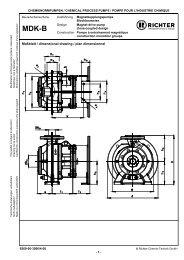
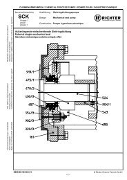
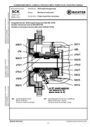
Series RSA Page 219 Sectional drawing9.1 Legend100 casing (housing)122 blind cover183 support bracket210 shaftincludes:505 shoulder ring562/1 parallel pinAdditional for oil bath lubrication411/3 seal ring421/x Rotary shaft seal638/1 constant-level-oiler672/1 venting/filling plug903/1 hex. head screw plug230 impeller321/x radial ball bearing330 bearing pedestal344 bracket361 rear bearing cover401 housing gasket412/x o-ring415/1 centering gasket523/x shaft sleeve524 shaft sleeve557/1 contact disc901/x hex. screw914/6 hex. socket screw932/x circlip940/1 key9285-050-en Revision 11TM 7903 Edition 07/2010
Series RSA Page 229.2 RSA long life grease lubrication9285-050-en Revision 11TM 7903 Edition 07/2010
Series RSA Page 239.3 RSA oil bath lubrication9285-050-en Revision 11TM 7903 Edition 07/2010-----
Series RSA Page 2410 Assembly aids10.1 Impeller wrench for open impeller<strong>Pump</strong> size No. of vanes Ident. No.RSA 1,5"x1"x6" 7RSA 3"x2"x6" 7RSA 1,5"x1"x8" 6RSA 3"x2"x8" 6Product descriptionThe torque to be transmitted, either during loosening or tightening, is achieved by the fact that the parallel pins ofthe impeller wrench engage in the spaces in the (open) impeller. The impeller is turned into the position you wantby turning the impeller wrench clockwise or counterclockwise.10.2 Clamping device for SCK single mechanical seals<strong>Pump</strong> sizeRSA group 1, WSH Ø 35 mmRSA group 2, WSH Ø 45 mmIdent. No.Product descriptionIn order to be able to set the check dimension (1 mm), the single mechanical seal clamping device is insertedbetween the lantern and the single mechanical seal. Owing to the lever action the single mechanical seal is pushedin the axial direction and positioned by means of a cylinder head screw.9285-050-en Revision 11TM 7903 Edition 07/2010
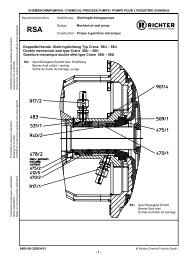
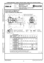
CHEMIENORMPUMPEN / CHEMICAL PROCESS PUMPS / POMPE POUR L'INDUSTRIE CHIMIQUEBaureihe/Series/Série Ausführung MagnetkupplungspumpeModification techniques possibles sans réservées!Graphique non à l'échelle!Dimensions valables uniquement revêtues d'une signature!RSAEinsatzgrenzen / operating limitsDesign Magnet drive pumpConstruction Pompe à entraînement magnétiqueTechnische Änderungen vorbehalten!Nicht maßstäblich!Maße nur mit Unterschrift verbindlich!This leaflet is subject to alteration!Drawing not to scale!Certified for construction purposes only when signed!9285-00-3030/4-00 © <strong>Richter</strong> Chemie-Technik GmbH- 1 -
<strong>Richter</strong> Chemie-Technik GmbHOtto-Schott-Straße 2D-47906 Kempenwww.richter-ct.comA Unit of IDEX CorporationKonformitätserklärung nach EN ISO//IEC 17050Declaration of Conformity according to EN ISO//IEC 17050ProduktProductBaureiheSeriesEU-RichtlinienEU-DirectiveModulChemiekreiselpumpe für Gleitringdichtungenfreies Wellenende oder als Aggregat 1)<strong>Chemical</strong> Centrifugal <strong>Pump</strong> for Mechanical SealsBare shaft or as unit 1)SCK, SCK-X, SCK-SRSA, RSI2006/42/EG Maschinenrichtlinie94/9/EG Explosionsschutzrichtlinie ATEXMachinery DirectiveEquipment explosive atmosphereInterne FertigungskontrolleProduction Quality AssuranceAngewandte EN 14121harmonisierte Normen EN 809Applied harmonised EN 13463-1StandardsKennzeichnung 2006/42/EG 2006/42/ECMarking 94/9/EG 94/9/EC II 2 GD IIC TX X 1)Die technische Dokumentation nach Richtlinie 94/9EG ist bei der u.a. benannten Stelle hinterlegt.The technical documentation is filed by below mentioned notified body according to directive 94/9/EC.Physikalische-Technische Bundesanstalt (PTB), D-38116 BraunschweigBaureiheSeriesRegistrier-Nr.Registered #BaureiheSeriesRegistrier-Nr.Registered #SCK 03ATEXD070 RSA 03ATEXD062SCK-X 03ATEXD070 RSISCK-S03ATEXD070Das Unternehmen <strong>Richter</strong> Chemie-Technik GmbH bescheinigt hiermit, dass die o.a. Baureihen diegrundsätzlichen Anforderungen der aufgeführten Richtlinien und Normen erfüllt.<strong>Richter</strong> Chemie-Technik GmbH confirms that the basic requirements of the above specified directives andstandards have been fulfilled.Bevollmächtigt für die Zusammenstellung der technischen Unterlagen nach 2006/42/EG:Authorised person compiled the technical files according to 2006/42/EG:A. Linges1) Gilt nicht für das Aggregat nach 94/9/EG (ATEX Leitfaden Juni 2009 Abschn. 3.7.5 2.a)1) Not valid for the unit according to 94/9/EG (ATEX Guideline June 2009 Paragraph 3.7.5 2.a)Kempen, 01.03.2010_________________________________________________________________G. Kleining A. LingesLeiter Forschung & EntwicklungLeiter QualitätsmanagementManager Research & DevelopmentQuality ManagerErstellt/Compiled: CRM/GK am/on: 01.03.2010 Seite/Page : 1 QM-Nr.: 0905-40-1037/4-01_deGenehmigt/Approved: CRQ/AL am/on: 19.03.2010 von/of : 1
<strong>Richter</strong> Chemie-Technik GmbHOtto-Schott-Straße 2D-47906 Kempenwww.richter-ct.comA Unit of IDEX CorporationKonformitätserklärung nach EN ISO/IEC 17050Declaration of Conformity according to EN ISO/IEC 17050ProduktProductChemiekreiselpumpe für Gleitringdichtungenals Aggregat<strong>Chemical</strong> Centrifugal <strong>Pump</strong> for Mechanical Sealsas unitBaureiheSeriesSCK, SCK-X, SCK-SRSA, RSIEU-RichtlinienEU-Directive2006/42/EG MaschinenrichtlinieMachinery DirectiveModulInterne FertigungskontrolleProduction Quality AssuranceAngewandte EN 14121harmonisierte Normen EN 809Applied harmonisedStandardsKennzeichnungMarking2006/42/EGDas Unternehmen <strong>Richter</strong> Chemie-Technik GmbH bescheinigt hiermit, dass die o.a. Baureihen diegrundsätzlichen Anforderungen der aufgeführten Richtlinien und Normen erfüllt.<strong>Richter</strong> Chemie-Technik GmbH confirms that the basic requirements of the above specified directives andstandards have been fulfilled.Bevollmächtigt für die Zusammenstellung der technischen Unterlagen nach 2006/42/EG:Authorised person compiled the technical files according to 2006/42/EG:A. LingesKempen, 01.07.2010_________________________________________________________________G. Kleining A. LingesLeiter Forschung & EntwicklungLeiter QualitätsmanagementManager Research & DevelopmentQuality ManagerErstellt/Compiled: CRM/GK am/on: 01.07.2010 Seite/Page : 1 QM-Nr.: 0905-40-1042/4-00-deGenehmigt/Approved: CRQ/AL am/on: 01.07.2010 von/of : 1
Safety Information / Declaration of No Objection Concerning the Contaminationof <strong>Richter</strong>-<strong>Pump</strong>s, -Valves and Components1 SCOPE AND PURPOSEEach entrepreneur (operator) carries the responsibility for the health and safety of hisemployees. This extends also to the personnel, who implements repairs with the operator orwith the contractor.Enclosed declaration is for the information of the contractor concerning the possiblecontamination of the pumps, valves and component sent in for repair. On the basis of thisinformation for the contractor is it possible to meet the necessary preventive action during theexecution of the repair.Note: The same regulations apply to repairs on-site.2 PREPARATION OF DISPATCHBefore the dispatch of the aggregates the operator must fill in the following declarationcompletely and attach it to the shipping documents. The shipping instructions indicated in therespective manual are to be considered, for example:• Discharge of operational liquids• remove filter inserts• lock all openings hermetically• proper packing• Dispatch in suitable transport container• Declaration of the contamination fixed outside!! on the packingPrepared: CRQ/Lam on: Feb. 15, 06 Page: 1 QM No.: 0912-16-2001_en/4-06Approved: CRQ/Zu on: Feb. 15, 06 of : 2
Declaration about the Contamination of<strong>Richter</strong> <strong>Pump</strong>s, -Valvesand ComponentsThe repair and/or maintenance of pumps, valves and components can only be implemented if a completely filled outdeclaration is available. If this is not the case, delay of the work will occur. If this declaration is not attached to thedevices, which have to be repaired, the transmission can be rejected.Every aggregate has to have it’s own declaration.This declaration may be filled out and signed only by authorized technical personnel of the operator.Contractor/dep./institute : Reason for transmitting Please mark the applicableRepair: subject to fee WarrantyStreet : Exchange: subject to fee WarrantyPostcode, city: Exchange/ Replacement already initiated/receivedContact person: Return: Leasing Loan for credit notePhone : Fax :End user :A. Details of <strong>Richter</strong>-product: Failure description:Classification:Article number:Equipment:Serial number:Application tool:Application process:B. Condition of the <strong>Richter</strong>-product: no 1) yes no Contamination : no 1) yesWas it in operation ? toxic Drained (product/operating supply item) ? caustic All openings hermetically locked! inflammable Cleaned ? explosive 2) If yes, with which cleaning agent: mikrobiological 2) and with which cleaning method: radioactive 3)1) if "no", then forward to D. other pollutant 2) Aggregates, which are contaminated with microbiological or explosive substances, are onlyaccepted with documented evidence of an approved cleaning.3)Aggregates, which are contaminated with radioactive substances, are not accepted in principle.C. Details of the discharged materials (must be filled out imperatively)1. With which materials did the aggregate come into contact ? Trade name and/or chemicaldesignation of operational funds and discharged materials, material properties, e.g. as persafety data sheet (e.g. toxic, inflammable, caustic)X Trade name: <strong>Chemical</strong> designation:a)b)c)d)no yes2. Are the materials specified above harmful to health ? 3. Dangerous decomposition products during thermal load ? If yes, which ones ?D. Mandatory declaration: We assure that the data in this explanation are truthful and complete and as a signatory I amable to form an opinion about this. We are aware that we are responsible towards the contractor for damages, which resultsfrom incomplete and incorrect data. We commit ourselves to exempt the contractor from claims for damages of thirdsresulting from incomplete or incorrect data. We are aware that we are directly responsible towards thirds, irrespective of thisdeclaration, which belongs in particularly to the employees of the contractor consigned with the handling repair of the product.Name of the authorized person(in block letters):Date Signature Company stampPrepared: CRQ/Lam on: Feb. 15, 06 Page: 2 QM No.: 0912-16-2001_en/4-06Approved: CRQ/Zu on: Feb. 15, 06 of : 2
FAXFax No. ()Pages (incl. cover sheet) ()To:()Contact person: Reference: Extension: E-Mail Address: Date:() () - () () ()Your order No.: ()Our Kom. No.: () Serial No.: ()Dear Sirs,The compliance with laws for the industrial safety obligates all commercial enterprises to protect theiremployees and/or humans and environment against harmful effects while handling dangerousmaterials.The laws are such as: the Health and Safety at Work Act (ArbStättV), the Ordinance on HarzadousSubstances (GefStoffV, BIOSTOFFV), the procedures for the prevention of accidents as well asregulations to environmental protection, e.g. the Waste Management Law (AbfG) and the WaterResources Act (WHG)An inspection/repair of <strong>Richter</strong> products and parts will only take place, if the attached explanation isfilled out correctly and completely by authorized and qualified technical personnel and is available.In principle, radioactively loaded devices sent in, are not accepted.Despite careful draining and cleaning of the devices, safety precautions should be necessaryhowever, the essential information must be given.The enclosed declaration of no objection is part of the inspection/repair order. Even if this certificate isavailable, we reserve the right to reject the acceptance of this order for other reasons.Best regardsRICHTER CHEMIE-TECHNIK GMBHEnclosures()Landesbank Rheinland-Pfalz, Mainz Kto. 110 145810 (BLZ 550 500 00)SWIFT: MALA DE 555 50 USt. Id. Nr. DE 811 127054Sitz der Gesellschaft: Kempen Amtsgericht Krefeld HRB 9635 Geschäftsführer: Dipl.-Ing. Günter NaasnerQM-Nr.: 0912-16-2001an_en/4-01