1 Technical data - Richter Chemie-Technik GmbH
1 Technical data - Richter Chemie-Technik GmbH
1 Technical data - Richter Chemie-Technik GmbH
- No tags were found...

Create successful ePaper yourself
Turn your PDF publications into a flip-book with our unique Google optimized e-Paper software.
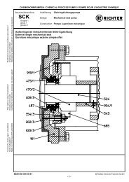
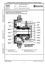
Series SCK, double mechanical seal to DIN EN 12756 Page 2List of ContentsList of Contents ........................................ 2Relevant documents ................................. 21 <strong>Technical</strong> <strong>data</strong> ...................................... 22 Safety, transport and storage ............. 32.1 Intended use ................................................ 33 Product description ............................. 34 Commissioning / Shutdown ................ 34.1 Initial commissioning ................................... 34.2 Mechanical seals ......................................... 34.2.1 Use in an explosive area ................................. 34.2.2 Double mechanical seal to DIN EN 12756 ..... 34.3 Inadmissible modes of operation and theirconsequences (examples) .......................... 45 Maintenance ......................................... 45.1 Dismantling of double mechanical seal toDIN EN 12756 ............................................. 45.1.1 Dismantling of back plate, impeller and matingring carrier ....................................................... 45.1.2 Dismantling of shaft sleeve .............................. 55.3 Notes on assembly ...................................... 56 Faults .................................................... 57 Sectional drawing ................................ 67.1 Legend ......................................................... 67.2 Double mechanical seal to DIN EN 12756 .. 6Relevant documents♦ Operating manual SCK long-life grease and oilbath lubrication9220-050-enOperating manual mechanical seal of themanufacturer1 <strong>Technical</strong> <strong>data</strong>Manufacturer :<strong>Richter</strong> <strong>Chemie</strong>-<strong>Technik</strong> <strong>GmbH</strong>Otto-Schott-Str. 2D-47906 KempenTelephone: +49 (0) 2152 146-0Fax: +49 (0) 2152 146-190E-Mail: richter-info@idexcorp.comInternet: http://www.richter-ct.comAuthorised person acc. to machinery directive2006/42/EG: Gregor KleiningDesignation :Series SCK, mechanical seal:♦ double, to DIN EN 12756Materials :Seal housing: Stainless steelWetted parts:Mechanical seal: SSiC, carbon, Al 2 O 3 , PTFE, FKM,FFKM etc., see also <strong>data</strong> sheetTemperature range : see installation andoperating manual SCK, Section 1Temperature classes : see installation andoperating manual SCK, Section 2.6.7.9220-063-en Revision 10TM 7827 Edition 03/2010
Series SCK, double mechanical seal to DIN EN 12756 Page 4The supply pressure is measured in bar at the pumpsuction nozzle. If no measuring point is available, thesupply pressure can be calculated using the followingformula.Using the same formula, the delivery pressure atQ=0 m 3 /h can be determined with the pumpcharacteristic curve.3H (mFS) x ρ (kg/dm )p (bar) =10,2p = supply pressure or delivery pressureH = supply height or delivery headρ = density4.3 Improper operation and theirconsequences (examples)Improper operation, even for a short time, canresult in serious damage to the unit.In connection with explosion protection,potential sources of ignition (overheating, electrostaticand induced charges, mechanical and electric sparks)may result from these inadmissible modes ofoperation; their occurrence can only be prevented byadhering to the intended use.For examples, see installation and operating manualSCK, Section 6.6.Are the available connections correctly made?SE - barrier fluid inletSA - barrier fluid outletSee sectional drawing in Section 7.2.5 MaintenanceThe regulations of the mechanical sealmanufacturer must always be observed.See also the installation and operating manualfor the SCK series.It is important to replenish in good time any barrierfluid which has escaped and to monitor the barrierfluid pressure.The minimum barrier fluid pressure must never beundershot as long as the pump housing is underpressureRefer also to the description of the pressurisationsystem used and Section 4.2.2.If the barrier fluid pressure is too high, this indicates adefect in the mechanical seal even though themechanical seal on the atmosphere side is completelytight.The pump must then be shut down so that no seriousdamage occurs.Substantial damage generally occurs if the aggressiveprocess medium enters the pressurisation system asa result of a drop in the barrier fluid pressure to belowthe minimum pressure.If there is a risk that pressure surges occur in theplant, precautions must be taken to prevent damage.To this end, for example, the barrier fluid pressure canbe increased.5.1 Dismantling of doublemechanical seal toDIN EN 12756Dismantling can be checked using the sectionaldrawings in Section 7 and Section 9 of theinstallation and operating manual SCK as well as thecomponents available.5.1.1 Dismantling of back plate, impellerand mating ring carrier First of all relieve the mechanical seal by undoingthe attachment screws 901/5. Undo screws 901/6 and washers 554/6 of thebearing pedestal / back plate. Undo back plate (for instructions, see Sections4.2.1 and 7.7.4 in the installation and operatingmanual SCK). Move the back plate almost up to the impeller withlight hammer blows. Bearing pedestal group 3:Labyrinth disc 555 must be secured withtwo bolts prior to the dismantling of theimpeller. For this purpose there are 2bores Ø5mm in the bearing pedestal. Thedouble mechanical seal is relieved of pressure asa result. See dismantling in Sections 7.7.1 and7.7.5 in the installation and operating manual SCK.9220-063-en Revision 10TM 7827 Edition 03/2010
Series SCK, double mechanical seal to DIN EN 12756 Page 5 Undo impeller 230 with a strap wrench orassembly wrench. Right-hand thread.For assembly aid for impeller, see Section 10.1 inthe installation and operating manual SCK.See also installation and operating manual SCK,Section 7.7.1. With some pump sizes the work sequence is to berepeated once or twice so that the cup springs950/1 can be completely relieved without movingthe shaft sleeve 524 in the rotating units 470 of themechanical seal. Then completely remove the impeller 230. Undo back plate (for instructions, see Sections4.2.1 and 7.7.4 in the installation and operatingmanual SCK). It may happen that the mating ring carrier 476 isremoved at the same time as the mating ring475/1. If the mating ring 475/1 is replaced, remove theanti-torsion insert stud 560/3.5.1.2 Dismantling of shaft sleeve Pull the shaft sleeve 524 with the rotating units470/1 and 470/2 which are still installed off theshaft. When changing the rotating unit, observe theoperating manual of the mechanical sealmanufacturer. Remove seal housing 483. Remove mating ring 475/2.5.2 Notes on assembly♦ Only use original spare parts.♦ Do not use any defective parts as otherwise thenext damage is pre-programmed.♦ The recommendations of the mechanical sealmanufacturer are to be observed.♦ Bearing pedestal group 3:Always make sure that when installing themechanical seal the labyrinth disc issecured by 2 bolts.The bolts must be removed again afterassembly of the impeller.♦ If the rotating units are moved by a key, the twoseal halves are to be pushed from both sides ontothe shaft sleeve. Otherwise the secondary sealwould be damaged on the sharp edges of the keygroove.♦ PTFE rings are often easier to install if they havebeen previously heated in hot water.♦ The mating ring carrier 476 is designed with ananti-torsion insert for the wetted mating ring. Itmust be ensured that the mating ring is properlyinstalled in this device.♦ With some mechanical seal types the rotating unitscan be better pushed over the shaft sleeve whendismantled.♦ Mount rotating unit 470/2 with pumping thread onthe impeller side.♦ The rotating units 470/1 and 470/2 must be flushwith the key 940/2.♦ When pushing on the mating ring 475/1, makesure that the position of the flat section matchesthat on the shaft.6 FaultsFaults may result from inadmissible modes ofoperation. Such inadmissible modes ofoperation – even brief ones – may causeserious damage to the unit.In connection with explosion protection, potentialsources of ignition (overheating, electrostatic andinduced charges, mechanical and electric sparks) canresult from these inadmissible modes of operation;their occurrence can only be prevented by adhering tothe intended use.Should there be any uncertainty about the remedy tobe applied, please inquire at your in-house pumpoffice or at the pump manufacturer's.See also Section 8 in the installation and operatingmanual of the SCK series.9220-063-en Revision 10TM 7827 Edition 03/2010
Series SCK, double mechanical seal to DIN EN 12756 Page 67 Sectional drawing7.1 Legend161400/2 flat gasket412/x O-ring470/x rotating unit475/x mating ring476 mating ring carrier483 seal housing524 shaft sleeve531/2 spring-type slotted pin560/3 stud901/5 hex. screw917/x screw-in pipe connector932/5 circlip940/3 keySE = barrier fluid inletSA = barrier fluid outlet / venting7.2 Double mechanical seal to DIN EN 12756View displaced by 90°9220-063-en Revision 10TM 7827 Edition 03/2010