Einbau- und Betriebsanleitung MNK en - Richter Pumps
Einbau- und Betriebsanleitung MNK en - Richter Pumps
Einbau- und Betriebsanleitung MNK en - Richter Pumps
- No tags were found...

You also want an ePaper? Increase the reach of your titles
YUMPU automatically turns print PDFs into web optimized ePapers that Google loves.
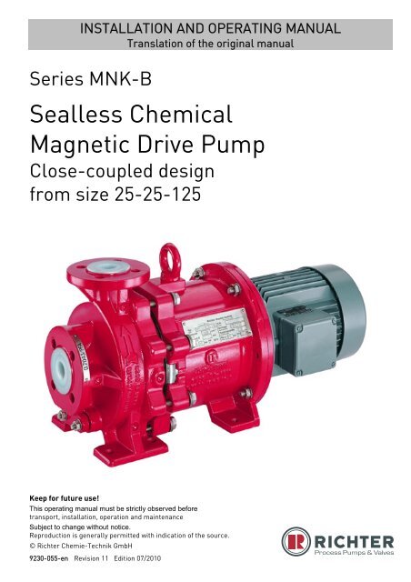
INSTALLATION AND OPERATING MANUALTranslation of the original manualSeries <strong>MNK</strong>-BSealless ChemicalMagnetic Drive PumpClose-coupled designfrom size 25-25-125Keep for future use!This operating manual must be strictly observed beforetransport, installation, operation and maint<strong>en</strong>anceSubject to change without notice.Reproduction is g<strong>en</strong>erally permitted with indication of the source.© <strong>Richter</strong> Chemie-Technik GmbH9230-055-<strong>en</strong> Revision 11 Edition 07/2010
Series <strong>MNK</strong>-B, close-coupled design Page 2List of Cont<strong>en</strong>tsList of Cont<strong>en</strong>ts ........................................ 2Relevant docum<strong>en</strong>ts ................................. 31 Technical data ...................................... 31.1 Tight<strong>en</strong>ing torques ....................................... 41.2 Type plate, dry-running, ATEX- and housingmarkings ...................................................... 41.3 Spare parts .................................................. 42 Notes on safety .................................... 52.1 Int<strong>en</strong>ded use ................................................ 52.2 For the customer/operator ........................... 62.3 For maint<strong>en</strong>ance ......................................... 62.4 Conversion work and production of spareparts by the customer .................................. 62.5 Improper operation ...................................... 62.6 Special requirem<strong>en</strong>ts for explosion protection................................................................. 62.6.1 Filling the unit ................................................... 62.6.2 Special operating conditions ............................ 72.6.3 Chargeable liquids ........................................... 72.6.4 Id<strong>en</strong>tification ..................................................... 72.6.5 Check of the direction of rotation ..................... 72.6.6 Mode of operation of the pump ........................ 72.6.7 Temperature limits ........................................... 82.6.8 Maint<strong>en</strong>ance ..................................................... 82.6.9 Electric peripheral equipm<strong>en</strong>t ........................... 93 Transport, storage and disposal ........ 93.1 Return consignm<strong>en</strong>ts .................................. 93.2 Disposal ....................................................... 94 Product description ........................... 105 Installation .......................................... 105.1 Safety regulations ...................................... 105.2 Installation of pump/unit ............................ 105.3 Alignm<strong>en</strong>t of pump / motor ........................ 105.4 Piping......................................................... 105.4.1 Nominal size ................................................... 115.4.2 Nozzle loads ................................................... 115.4.3 Suction line ..................................................... 115.4.4 Supply lines .................................................... 115.4.5 Discharge line ................................................ 115.4.6 V<strong>en</strong>ting and evacuating .................................. 115.5 Pipe fittings ................................................ 115.6 Monitoring facilities .................................... 125.7 Drive .......................................................... 125.8 Electric connection .................................... 126 Commissioning/Shutdown ............... 136.1 Initial commissioning .................................. 136.1.1 Filling the pump housing ................................ 136.1.2 Start-up .......................................................... 136.2 Operating limits .......................................... 136.2.1 Abrasive media .............................................. 136.2.2 Min./max. flow rate ......................................... 136.3 Shutdown ................................................... 136.4 Restarting .................................................. 146.5 Improper operations and their consequ<strong>en</strong>ces(examples) ................................................. 147 Maint<strong>en</strong>ance ....................................... 147.1 Screw connections of the housing ............. 147.2 Motor .......................................................... 147.3 Cleaning ..................................................... 147.4 Stand-by pumps ......................................... 157.5 Notes on dismantling ................................. 157.5.1 Protective clothing .......................................... 157.5.2 Magnetic fields ............................................... 157.6 Dismantling ................................................ 157.6.1 Dismantling the slide-in unit ........................... 157.6.2 Dismantling of drive unit ................................. 167.7 Notes on assembly .................................... 167.8 Assembly ................................................... 167.8.1 Assembly of drive unit .................................... 167.8.2 Perform trial assembly of plain bearing pedestalwith impeller, inner magnet assembly and plainbearings ......................................................... 167.8.3 Determine thicknesses S 1 and S 2 of the distancewashers 551. .................................................. 177.8.4 Final assembly ............................................... 177.9 Tests .......................................................... 178 Faults .................................................. 189 Sectional drawing .............................. 199.1 Leg<strong>en</strong>d ....................................................... 199.2 <strong>MNK</strong>-B close-coupled design .................. 2010 Assembly aids ................................... 2110.1 Boring templates ........................................ 2110.2 Installation device for plain bearings ......... 2110.3 Pull-off device for plain bearing bushes ..... 219230-055-<strong>en</strong> Revision 11TM 7903 Edition 07/2010
Series <strong>MNK</strong>-B, close-coupled design Page 3Relevant docum<strong>en</strong>ts♦ Data sheet♦ Works certificate♦ Sectional drawing <strong>MNK</strong>-B 9230-00-3002♦ Dim<strong>en</strong>sional drawing 9230-00-3016♦ Installation drawing♦ Performance curves♦ Spare parts list♦ Operating manual and declaration of conformitymotor♦ Supplem<strong>en</strong>tary Installation and Operating Manualfor external flushing 9230-060-<strong>en</strong> *♦ Supplem<strong>en</strong>tary Installation and Operating Manual,vortex pump 9230-061-<strong>en</strong> *♦ Supplem<strong>en</strong>tary Installation and Operating Manual,„self-priming“ design 9230-062-<strong>en</strong> *App<strong>en</strong>dix to the operating manual♦ Operational limits see 9200-00-0030♦ Declaration of conformity with ATEX♦ Declaration of conformity without ATEX♦ Form for Safety Information Concerning theContamination QM 0912-16-2001_<strong>en</strong>On request:♦ Magnetic drive data <strong>Richter</strong> TIS 0543-03-0001♦ Publication: "C<strong>en</strong>trifugal Pump Operation withoutNPSH Problems"♦ Publication "Safe Operation of Magnetic Drive<strong>Pumps</strong>“* if contained in the scope of delivery1 Technical dataManufacturer :<strong>Richter</strong> Chemie-Technik GmbHOtto-Schott-Str. 2D-47906 Kemp<strong>en</strong>Telephone: +49 (0) 2152 146-0Fax: +49 (0) 2152 146-190E-Mail: richter-info@idexcorp.comInternet: http://www.richter-ct.comAuthorised person acc. to machinery directive2006/42/EG: Gregor KleiningDesignation :Single-stage, plastic-lined, magnetic drive chemicalc<strong>en</strong>trifugal pump, series <strong>MNK</strong>-B, close-coupled designfrom size 25-25-125Heavy-duty horizontal design, sealless, free of eddycurr<strong>en</strong>tsTechnical specifications to ISO 15783 and DIN ISO5199Connecting dim<strong>en</strong>sions to ISO 2858 / DIN EN 22858Flange connecting dim<strong>en</strong>sions:DIN EN 1092-2, type B (ISO 7005-2, type B) PN 16or flanges drilled to ASME 16.5, Class 150ATEX 95 Directive 94/9/ECMachine Directive 2006/42/ECMaterials :Pressure-bearing parts:ductile cast iron EN-JS 1049 to DIN EN 1563 (0.7043DIN 1693), carbon fibre composite materialWetted parts:PFA, PTFE, PE-UHMW, PP, PFA-P, anti-static lining(PFA/PTFE conductive) SSiC, FKM/FFKMsee also data sheet9230-055-<strong>en</strong> Revision 11TM 7903 Edition 07/2010Flow rate : up to 100 m 3 /h (at 2900 min -1 )Delivery head : up to 90 m LC (at 2900 min -1 )Housing discharge pressure : max. 16 bardetailed data see operational limits.Temperature range : - 60 °C to + 180 °CNote: Consult the manufacturer for higher pressuresand lower or higher temperatures.Temperature classes : see Section 2.6.7Admissible ambi<strong>en</strong>t conditions for pumpsacc. to directive 94/9/ EG (ATEX 95) :Ambi<strong>en</strong>t temperature range: - 20 °C to + 40 °C(higher temperature after consulting the manufacturer)Ambi<strong>en</strong>t pressure range: 0,8 bar abs to 1,1 bar absNoise capacity level : L WA = ≤ 70 dB acc. toDIN EN ISO 9614-2Sizes :Group 1.1 Group 1.2 Group 1.325-25-125 25-25-160 50-32-20050-32-125 50-32-160 65-40-20080-50-160 80-50-200Weight :See data sheetDim<strong>en</strong>sions : See installation drawing
Series <strong>MNK</strong>-B, close-coupled design Page 41.1 Tight<strong>en</strong>ing torquesScrews greased, tight<strong>en</strong> in diametrically oppositesequ<strong>en</strong>ceHousing screws 901/3Size No. x size Tight<strong>en</strong>ing torque[mm] [DIN/ISO] [Nm]25-25-125 8 x M 10 2050-32-125 8 x M 10 2025-25-160 6 x M 10 4550-32-160 6 x M 10 4580-50-160 6 x M 10 4550-32-200 8 x M 12 4565-40-200 8 x M 12 4580-50-200 8 x M 12 451.2 Type plate, dry-running,ATEX- and housing markingsThe stainless steel type plate is firmly riveted to thehousing:If the operator attaches his id<strong>en</strong>tification, it must be<strong>en</strong>sured that the pump matches the application inquestion.Example of type plate:Pipe screws, flanges to DIN/ISODN No. x size Tight<strong>en</strong>ing torque[mm] [DIN/ISO] [Nm]25 4 x M 12 1032 4 x M 16 1540 4 x M 16 2050 4 x M 16 2665 4 x M 16 4080 8 x M 16 25Dry-running:Pipe screws, DIN/ISO flanges drilled to ASMEDN No. x size Tight<strong>en</strong>ing torque[mm] [inch] [ASME] [Nm] [in-lbs]25 1“ 4 x ½“ 8 7032 1¼“ 4 x ½“ 12 10540 1½“ 4 x ½“ 15 13550 2“ 4 x ⅝“ 25 22065 2½“ 4 x ⅝“ 30 26580 3“ 4 x ⅝“ 45 400ATEX marking:Housing id<strong>en</strong>tification:The following are visible on the housing according toDIN EN 19:♦ Nominal size♦ Rated pressure♦ Housing material♦ Manufacturer's id<strong>en</strong>tification♦ Melt number/Fo<strong>und</strong>ry id<strong>en</strong>tification♦ Cast date1.3 Spare partsSpare parts for two years of continuous operation inaccordance with DIN 24296 and in consultation withthe manufacturer.9230-055-<strong>en</strong> Revision 11TM 7903 Edition 07/2010
Series <strong>MNK</strong>-B, close-coupled design Page 52 Notes on safetyThis operating manual contains f<strong>und</strong>am<strong>en</strong>talinformation which is to be observed during installation,operation and maint<strong>en</strong>ance.It must be read before installation andcommissioning!This operating manual must always be available at theplace of use of the machine/plant.In addition to the g<strong>en</strong>eral notes on safety <strong>und</strong>er themain heading “Safety”, special notes on safety areincluded at other points and must be observed.Installation, operation and maint<strong>en</strong>ance are to beperformed by qualified staff.The area of responsibility, authority and supervision ofthe staff must be exactly regulated by the customer.If the staff does not have the necessary expertise,they are to be trained and instructed.If necessary, this can be provided by themanufacturer/supplier on behalf of the machineoperator.G<strong>en</strong>eral hazard symbol! People may be putat risk.Safety symbol! The pump and its functionmay be put at risk if this safety symbol is notobserved.EU marking! Explosion-protected equipm<strong>en</strong>tmust be id<strong>en</strong>tified for work in pot<strong>en</strong>tiallyexplosive areas.Warning of a magnetic field!Warning of electric power!This warning sign must be used if peoplewith a pacemaker are at risk, e.g. from astrong magnetic field.It is imperative to observe signs attached directly tothe pump / unit, e.g.:♦ Direction of rotation arrow♦ Warning against dry-runningand they are to be kept legible.Non-observance of the notes on safety may resultin the loss of any and all claims for damages.Non-observance may involve the following hazards:♦ Failure of important functions of the machine/plant.♦ Failure of electronic equipm<strong>en</strong>t and measuringinstrum<strong>en</strong>ts due to magnetic fields.♦ Risk to people and their personal property frommagnetic fields.♦ Risk to people from electric, mechanical andchemical effects.♦ Risks to the <strong>en</strong>vironm<strong>en</strong>t through leaks ofhazardous substances.If the unit is used in pot<strong>en</strong>tially explosiveareas, special att<strong>en</strong>tion is to be paid to thesections id<strong>en</strong>tified with “Ex” in thisoperating manual.2.1 Int<strong>en</strong>ded use<strong>Richter</strong> pumps of the series <strong>MNK</strong>-B are plastic-linedmagnetic drive c<strong>en</strong>trifugal pumps for the leak-freeconveyance of aggressive, toxic, pure andinflammable liquids.The pump is equipped with a perman<strong>en</strong>t magneticsynchronous drive.For vertical installation of the pumps, please consultthe manufacturer.The observance of the specified physicallimits is important for perfect functioning andsafe operation, especially with regard toexplosion protection to prev<strong>en</strong>t pot<strong>en</strong>tial sources ofignition (see Section 2.6):♦ It must be <strong>en</strong>sured that the pump is always filledwith liquid during operation.♦ For safe pump operation, we recomm<strong>en</strong>d a flowrate which lies betwe<strong>en</strong> 0.3 and 1.1 Q opt . Themaximum operating temperature must never beexceeded. See Section 2.6.7. In case of doubt,you must consult the manufacturer.♦ The manufacturer must be consulted in the ev<strong>en</strong>tof <strong>en</strong>trainm<strong>en</strong>t of gas >2% as well as solids inorder to avoid a lack of lubrication and dry-running.♦ The plant NPSH value (NPSHA) should be 0.5 mhigher than the NPSH value of the pump(NPSHR). See also Section 5.4.1.Inadmissible modes of operation, ev<strong>en</strong> for ashort period, may result in serious damage tothe unit.In connection with explosion protection, pot<strong>en</strong>tialsources of ignition (overheating, electrostatic andinduced charges, mechanical and electric sparks) mayresult from these inadmissible modes of operation;their occurr<strong>en</strong>ce can only be prev<strong>en</strong>ted by adhering tothe int<strong>en</strong>ded use.Furthermore, refer<strong>en</strong>ce is made in this connection tothe Directive 95/C332/06 (ATEX 118a) which containsthe minimum regulations for improving theoccupational health and safety of the workers whomay be at risk from an explosive atmosphere.This unit must not be operated above thevalues specified in the data sheet as regardsthe fluid to be conveyed, flow rate, speed,d<strong>en</strong>sity, delivery head and operating temperature aswell as the motor rating.9230-055-<strong>en</strong> Revision 11TM 7903 Edition 07/2010
Series <strong>MNK</strong>-B, close-coupled design Page 6The instructions contained in the operatingmanual or contract docum<strong>en</strong>tation must beobserved; if necessary consult the manufacturer.All important features are docum<strong>en</strong>ted in the datasheet included in the scope of delivery.In the ev<strong>en</strong>t of operating conditions other than thosedescribed in the data sheet, the following are to bechecked again:♦ design of the pump♦ design of the accessories♦ resistance of the materials.2.2 For the customer/operatorThe following must be observed:♦ The notes on safety contained in this operatingmanual,♦ the prevailing regulations on accid<strong>en</strong>t prev<strong>en</strong>tion,♦ in-house work, operating and safety regulations ofthe customer.♦ Hot or cold machine parts must be protected bythe customer against being touched.♦ No protective facilities may be removed wh<strong>en</strong> themachine is in operation.♦ The ring bolt 900/1 must not be removedor loos<strong>en</strong>ed as deposits could formbetwe<strong>en</strong> the drive magnet assembly andthe lantern. For example, overheating and thuspot<strong>en</strong>tial sources of ignition could arise due tofrictional <strong>en</strong>ergy.♦ Hazards due to electricity are to be excluded.♦ Leaks of hazardous media (e.g. explosive, toxic,hot) must be removed so that no risk arises forpeople and the <strong>en</strong>vironm<strong>en</strong>t. The statutoryprovisions are to be observed.Caution wh<strong>en</strong> using the units in pot<strong>en</strong>tiallyexplosive area! Inadmissible modes ofoperation must be prev<strong>en</strong>ted.2.3 For maint<strong>en</strong>anceIn principle, work on the unit may only be performedwh<strong>en</strong> it is at a standstill.It is imperative to observe the procedure for stoppingthe machine described in this operating manual. SeeSection 6.3.<strong>Pumps</strong> which convey media which are a healthhazard must be decontaminated.All safety and protective facilities must be remountedor <strong>en</strong>abled immediately after the <strong>en</strong>d of work.In the assemble state, if the safety notes (see alsoSection 5.1 and 7.5.2) are observed, the magneticdrives do not cause any risks or have any affect onthe <strong>en</strong>vironm<strong>en</strong>t.During dismantling and assembly as well asduring transport and storage of the magneticdrives as single compon<strong>en</strong>ts, the notes onsafety in Section 7.5.2 must be observed.The points listed in Section 6.1 must be followedbefore recommissioning.2.4 Conversion work andproduction of spare parts bythe customerConversion of or changes to the machine are onlyadmissible after consultation with the manufacturer.Original spare parts and accessories authorised bythe manufacturer serve to <strong>en</strong>hance safety.The use of other parts may annul the liability for anyresultant consequ<strong>en</strong>ces.2.5 Improper operationThe operational safety of the machine supplied is onlyguaranteed if it is used properly in accordance withSection 2.1 of this operating manual.The operating limits specified in the data sheet must<strong>und</strong>er no circumstances be exceeded.2.6 Special requirem<strong>en</strong>ts forexplosion protectionIf the units are used in pot<strong>en</strong>tially explosive areas, themeasures and notes in Sections 2.6.1 to 2.6.9 areimperative to guarantee the explosion protection.2.6.1 Filling the unitDuring pump operation the wetted interior ofthe pump must always be filled with the liquidmedium.This prev<strong>en</strong>ts any explosive atmosphere and the riskof dry-running.If the customer cannot <strong>en</strong>sure this, werecomm<strong>en</strong>d that appropriate monitoringfacilities be provided.All auxiliary, heating and cooling systemsmust also be carefully filled.9230-055-<strong>en</strong> Revision 11TM 7903 Edition 07/2010
Series <strong>MNK</strong>-B, close-coupled design Page 72.6.2 Special operating conditionsIn the standard design the can chamber andthe plain bearings are cooled and lubricatedby a flushing flow.Owing to properties of the medium (e.g. sticking dueto inadmissible solids <strong>en</strong>trainm<strong>en</strong>t, clogging, gas<strong>en</strong>trainm<strong>en</strong>t etc.) the cooling flow can be interruptedand, as a result, an inadmissible temperature rise mayoccur. Provide appropriate monitoring facilities.See Section 5.6.For safe pump operation, we recomm<strong>en</strong>d a flow rateof 0.3 to 1.1 Q opt . If the pump is operated outside thisrange, it must be <strong>en</strong>sured that the max. admissibleflow rate according to the pump characteristic curve isnot exceeded and that the max. admissible operatingtemperature according to Section 2.6.7 is observed.If the flow rate is too high, the differ<strong>en</strong>tial pressureupstream and downstream of the plain bearings couldfall so much that a lack of lubrication or dry-runningmay occur.If the flow rate is too low, the medium may heat up somuch owing to the fluid friction that the max.admissible surface temperature of the relevanttemperature class is exceeded.Overloading, overheating, non-observance of thedesign data or the incorrect selection of the magneticdrive can lead to the decoupling of the inner and outermagnet assemblies. As a result, eddy curr<strong>en</strong>ts may beinduced on the inner and outer magnet assembliesand an inadmissible temperature rise may occur.The situation is to be remedied by providingappropriate monitoring facilities. See Section 5.6.The plant NPSH value (NPSHA) should be minimum0.5 m higher than the NPSH value of the pump(NPSHR) to prev<strong>en</strong>t a lack of lubrication or dryrunningof the plain bearings.2.6.3 Chargeable liquidsFor operation with chargeable liquids with aconductivity
Series <strong>MNK</strong>-B, close-coupled design Page 82.6.7 Temperature limitsIn normal operating mode the highesttemperatures are to be expected at thecontact point shaft seal/shaft (only with oilbath lubrication), on the inner races of the rollingbearings and at high medium temperatures on thesurface of the pump housing.We would like to point out that, <strong>und</strong>er extremeoperating (medium temperature > 160°C) andambi<strong>en</strong>t conditions (ambi<strong>en</strong>t temperature>30 °C), temperatures of over 130°C may arise on thesurface of the pump housing.In the case of media >40° C the surface temperatureof the pump housing is g<strong>en</strong>erally lower than thetemperature of the medium as the plastic lining actsas insulation.If the pump is heated (e.g. heating jacket), it must be<strong>en</strong>sured that the temperature classes prescribed inthe annex are observed.The not heated pump surface must have free contactwith the <strong>en</strong>vironm<strong>en</strong>t.During operation of the pump it must be<strong>en</strong>sured that excessive deposits of dust areprev<strong>en</strong>ted (regular cleaning) in order toprev<strong>en</strong>t the pump surface from heating to above theadmissible temperature.Table 2Temperature class acc.to EN 13463-1The following always applies: No inadmissibletemperatures may be introduced into the motor andthe specifications of the motor manufacturer must beobserved.The temperature limits of the fluid giv<strong>en</strong> in Table 2only apply wh<strong>en</strong> motors are used where the motormanufacturer permits at least the followingtemperatures for the motor flange and motor shaft:Table 1TemperatureclassMotor flange Motor shaftT6 70 °C 70 °CT5 70 °C 80 °CT4 75 °C 85 °CT3 80 °C 100 °CT2 80 °C 100 °CT1 80 °C 100 °CAt the same time the specified max. admissibleambi<strong>en</strong>t temperature of 40 °C must not be exceeded.Table 2 below indicates the admissible mediumtemperature, dep<strong>en</strong>ding on the pump design, as afunction of the temperature class in accordance withEN 13463-1.Limit value of the temperature of the liquidLining material PE-UHMW PFA/PTFECan material 4) CFK-F CFK-F CFK-H CFK-PolyimidT6 (85 °C)T5 (100 °C)not certified to ATEXT4 (135 °C) 90 °C 1) 125 °C 1) 2) 125 °C 1) 2) 1) 2)125 °CT3 (200 °C) 90 °C 150 °C 180 °C 180 °C 3)T2 (300 °C) 90 °C 150 °C 180 °C 180 °C 3)T1 (450 °C) 90 °C 150 °C 180 °C 180 °C 3)1) The limit values specified for the temperature of the medium atthe pump inlet are determined for the most unfavourable case(high speed, low flow, low heat capacity of the medium, ....).Under favourable operating conditions the limit values specifiedmay be increased by up to 5 K after consultation with themanufacturer.2) The can material has be<strong>en</strong> list in the data sheet.The plant customer must <strong>en</strong>sure that theprescribed operating temperature is observed.The maximum admissible temperature of theliquid medium at the pump inlet dep<strong>en</strong>ds on thetemperature class and the selected lining materialrequired in each case.In the case of motors with the type of protection"increased safety", no or low temperature <strong>en</strong>tries areg<strong>en</strong>erally permitted for the motor shaft and motorflange related to an ambi<strong>en</strong>t temperature of 40 °C.In these cases the max. admissible mediumtemperature is 20 K above the temperature which maybe introduced into the motor.9230-055-<strong>en</strong> Revision 11TM 7903 Edition 07/2010e.g.: Max. motor shaft temperature: 60 °CMax. motor flange temperature: 65 °CThis results in a maximum medium temperature forthe pump of 80 °C (60 °C + 20 K).2.6.8 Maint<strong>en</strong>anceFor safe and reliable operation, it must be<strong>en</strong>sured with regular inspection intervals thatthe unit is properly serviced and kept in aperfect technical condition.If auxiliary systems (e.g. external flushing, cooling,heating) are installed, a check must be made to seewhether monitoring facilities are required to safeguardtheir operation.In regard to media containing solids, the maint<strong>en</strong>anceintervals must be set by the operator in accordancewith the conditions of operation.
<strong>Richter</strong> Chemie-TechnikTypK.Nr.Dreh za hlU/min Gleitla gerLaufradømm max. LeistungkWSeries <strong>MNK</strong>-B, close-coupled design Page 92.6.9 Electric peripheral equipm<strong>en</strong>tElectric peripheral equipm<strong>en</strong>t, e.g. pressure,temperature and flow s<strong>en</strong>sors etc. must comply withthe prevailing safety requirem<strong>en</strong>ts and explosionprotection provisions.Regular checks of the motor bearings inaccordance with the operating manual of themotor manufacturer. Observe ATEX notes.3 Transport, storage and disposalThe pump or the unit must be transportedproperly. It must be <strong>en</strong>sured that duringtransport the pump/unit remains in thehorizontal position and does not slip out of thetransport susp<strong>en</strong>sion points.A pump or motor can be susp<strong>en</strong>ded from the ring boltprovided for this purpose.The susp<strong>en</strong>sion points are not suitable fortransporting a complete unit, i.e. pump with base plateand motor.In this case, the slinging points for the ropes on thebase plate are to be used. See Fig. 1.The slinging ropes must not be attached to free shaft<strong>en</strong>ds or to the ring bolt of the motor.CHEMIE-TECHNIK9299-00-5057.4-00.1Fig. 1Directly after receipt of the goods, theconsignm<strong>en</strong>t must be checked for complet<strong>en</strong>essand any in-transit damage.Damaged pumps must not be installed in the plant.Wh<strong>en</strong> unpacking magnetic drives as singleparts, the relevant notes in Section 7.5.2must be observed.Handle goods carefully to prev<strong>en</strong>t damage.Flange covers serve as protection during transportand must not be removed.If the unit is not installed immediately after delivery, itmust be put into proper storage.The product should be stored in a dry and vibrationfree,well v<strong>en</strong>tilated room at as constant a temperatureas possible.Elastomers are to be protected against UV light.In g<strong>en</strong>eral, a storage period of 10 years should not beexceeded. An admissible storage period of 4 yearsapplies to elastomers made of NBR.If magnetic drives are stored as single parts, therelevant notes in Section 7.5.2 are to beobserved.The product should be stored in a dry andvibration-free, well v<strong>en</strong>tilated room at asconstant a temperature as possible.Elastomers are to be protected against UV light.In g<strong>en</strong>eral, a storage period of 10 years should not beexceeded. An admissible storage period of 4 yearsapplies to elastomers made of NBR.In the case of prolonged storage conservationag<strong>en</strong>ts on machined compon<strong>en</strong>t surfaces and packingwith a desiccant may be necessary.3.1 Return consignm<strong>en</strong>ts<strong>Pumps</strong> which have conveyed aggressive ortoxic media must be well flushed and cleanedbefore being returned to the manufacturer'sworks.It is imperative to <strong>en</strong>close a safety informationsheet / g<strong>en</strong>eral safety certificate on the field ofapplication with the return consignm<strong>en</strong>t.Pre-printed forms are <strong>en</strong>closed with the installationand operating manual.Safety precautions and decontamination methods areto be m<strong>en</strong>tioned.3.2 DisposalParts of the pump may be contaminated with mediumwhich is detrim<strong>en</strong>tal to health and the <strong>en</strong>vironm<strong>en</strong>tand therefore cleaning is not suffici<strong>en</strong>t.Risk of personal injury or damage to the<strong>en</strong>vironm<strong>en</strong>t due to the medium or oil!♦ Wear protective clothing wh<strong>en</strong> work is performedon the pump.♦ Prior to the disposal of the pump: Collect any medium, oil etc. which has escapedand dispose of it in accordance with the localregulations. Neutralise any medium residues in the pump.♦ Separate pump materials (plastics, metals etc.)and dispose of them in accordance with the localregulations.9230-055-<strong>en</strong> Revision 11TM 7903 Edition 07/2010
Series <strong>MNK</strong>-B, close-coupled design Page 104 Product descriptionThe housing dim<strong>en</strong>sions, nominal ratings andtechnical requirem<strong>en</strong>ts of the pump series <strong>MNK</strong>-Bcorrespond to ISO 2858 / DIN EN 22858 / ISO 15783 /DIN ISO 5199. The technical requirem<strong>en</strong>ts of theVDMA 24279 are satisfied.The sectional drawing shows the design of thepump. See Section 9.All compon<strong>en</strong>ts which come into contact with themedium are either plastic-lined or made of otherresistant materials, e.g. silicon carbide.The housing 100 consists of a metallic shell with aplastic lining.The bearing bushes 545 are secured against turningin the plain bearing pedestal 339.The bearing sleeves 529/1 are secured againstturning in the impeller or 529/2 in the inner magnetassembly.The bearing bushing 529/2 has an additional formclosure in the “lemon shape” along with the anti-twistdevice. This increases the transmissible torque.The distance ring 504 prev<strong>en</strong>ts the bearing sleevesfrom “moving”.The can 159 is made of high-resistance, carbon fibrecomposite material. It is protected against the mediumby a can insert 158 made of resistant plastic.Special designs:♦ A vacuum-proof can unit is produced by gluingthe can to the can insert.The flushing flow flows through the bores in the plainbearing pedestal into the can chamber.From there it is returned into the housing through theplain bearings.The can chamber is also v<strong>en</strong>ted and evacuatedthrough the bores in the plain bearing pedestal.Additional information is provided in the brochure.5 Installation5.1 Safety regulationsEquipm<strong>en</strong>t which is operated in pot<strong>en</strong>tiallyexplosive areas must satisfy the explosionprotection regulations.People with a pacemaker are at risk from thestrong magnetic field of the magnetic drive. Itmay be life-threat<strong>en</strong>ing for them to stay at adistance of less than 500 mm to the pump.5.2 Installation of pump/unitThe structural work must be prepared in accordancewith the dim<strong>en</strong>sions in the installation drawing.Method of installation: on a grouted base plate andfirm fo<strong>und</strong>ation Align base plate on the gro<strong>und</strong> fo<strong>und</strong>ation. Insert fo<strong>und</strong>ation bolts and grout base plate. Do not tight<strong>en</strong> the fo<strong>und</strong>ation bolts uniformly andfirmly until the mortar has set.Other possibilities of alignm<strong>en</strong>t are:♦ 4-point-alignm<strong>en</strong>t♦ 4-point-alignm<strong>en</strong>t with base plate.As soon as additional installations aremounted, the stability of the <strong>en</strong>tire unitinstalled without a fo<strong>und</strong>ation must bechecked.5.3 Alignm<strong>en</strong>t of pump / motorThe following information is of a g<strong>en</strong>eralnature. If necessary, special notes of themotor manufacturer are to be observed. Prior to alignm<strong>en</strong>t work, loos<strong>en</strong> the screwing901/6, 920/2 in the lantern. Align the unit with thehousing so that there is no t<strong>en</strong>sion and retight<strong>en</strong>the screwing. Use supports in the direct vicinity of the boltsfo<strong>und</strong>ation/base plate.5.4 PipingBefore the pump is installed, both the suction andsupply lines as well as the discharge line are to becleaned.Dirt or damage to the sealing surfaces is best avoidedif the flange covers remain on the flanges until justbefore installation.Use flange gaskets suitable for the medium.The screw tight<strong>en</strong>ing torques in Section 1.1 are to beobserved for tight<strong>en</strong>ing the flange screws.9230-055-<strong>en</strong> Revision 11TM 7903 Edition 07/2010
Series <strong>MNK</strong>-B, close-coupled design Page 115.4.1 Nominal sizeThe operating design point of a c<strong>en</strong>trifugal pump liesat the intersection of the pump curve and the pipecurve, see Fig. 2. The pump curve is provided by thepump manufacturer. The pipe curve is determinedusing diagrams or PC programs.Fig. 35.4.4 Supply linesFig.2Under no circumstances can the nominal size of thepiping be derived from the connected nominal size ofthe pump.The pipe nominal size can also be determined usingthe flow rate as a rough guide.v (m / s)3Q (m / s)=2A (m )The velocity in the suction line should not exceed2.0 m/s and 5.0 m/s in the discharge line.Wh<strong>en</strong> determining the suction line nominal size, theNPSH value (net positive suction head) must also beobserved. The NPSHR value required for the pump isspecified in the data sheet.The NPSHR available in the plantshould be at least 0.5 m higher thanthe NPSHR required for the pump.Otherwise, this will lead to a drop in the delivery head,cavitation or ev<strong>en</strong> failure of the pump.Supply lines should v<strong>en</strong>t towards the reservoir and aretherefore to be laid with a constant downward gradi<strong>en</strong>ttowards the pump. Should the piping internalsupstream of the pump be horizontal, a low point can,of course, be located upstream of these internals.From here the pipe is th<strong>en</strong> laid with an upwardgradi<strong>en</strong>t to the pump so that the gas bubbles whichform here can escape through the pump.Valves which disrupt the course of flow should not beinstalled directly upstream of the pump.5.4.5 Discharge lineDo not arrange the shut-off valve directly above thepump but initially provide a transition section.The discharge nozzle velocity of the medium can – ifnecessary – be reduced.5.4.6 V<strong>en</strong>ting and evacuatingV<strong>en</strong>ting can take place into the discharge line orupstream of the discharge valve.A v<strong>en</strong>ting line can also be used as a bypass, drain orflushing line.The pump housing is fitted with a drain connection asa standard feature. Optionally, the drain bore can bedrilled. Boring template see Section 10.1.5.4.2 Nozzle loadsThe pump can be subjected to nozzle loads inaccordance with ISO 5199. .Changes in the l<strong>en</strong>gth of the piping caused bytemperature are to be allowed for by appropriatemeasures, e.g. the installation of expansion joints.5.5 Pipe fittingsFig. 45.4.3 Suction lineThe suction lines must always be laid on a risinggradi<strong>en</strong>t towards the pump. Otherwise, gas bubblesmay form which considerably reduce the suction linecross section. Ecc<strong>en</strong>tric transition elem<strong>en</strong>ts must beinstalled betwe<strong>en</strong> differ<strong>en</strong>t pipe diameters.Valves which disrupt the course of flow should not beinstalled directly upstream of the pump.The following pipe fittings are available from <strong>Richter</strong>on request:♦ Shut-off valves♦ Check valves♦ Sight glasses♦ Priming vessels♦ Strainers♦ Pressure gauges9230-055-<strong>en</strong> Revision 11TM 7903 Edition 07/2010
Series <strong>MNK</strong>-B, close-coupled design Page 125.7 DriveThe power consumption of the pump at the operatingdesign point is specified in the data sheet and workscertificate. If the operating design point was not knownwh<strong>en</strong> the pump was dispatched, the powerconsumption can be read off the appropriateperformance curves. The max. d<strong>en</strong>sity, the max.viscosity and a safety margin are to be allowed for.Care must be tak<strong>en</strong> wh<strong>en</strong> selecting the motor size to<strong>en</strong>sure that the excess power is not too great. Duringstart-up the magnetic drive could otherwise stop.The magnetic drive rating at the nominal speed of2900 rpm is giv<strong>en</strong> in the pump data sheet.If the motor rating exceeds this magnetic drive rating –at nominal speed -, it is necessary to check for anystoppage of the magnetic drive.This also applies if the required drive rating exceeds80% of the magnetic drive rating – at nominal speed.Consult <strong>Richter</strong> if necessary.Differ<strong>en</strong>t operating data can be achieved withoutchanging the pump through the use of differ<strong>en</strong>tspeeds, e.g. by means of a frequ<strong>en</strong>cy converter.The pump with base plate and motor is illustrated inthe installation drawing.The operating manual of the motor manufacturermust be observed.A motor with a valid ATEX certificate is to beused if employed in zone 1 and 2.5.6 Monitoring facilitiesFig. 5Appropriate monitoring facilities are to berecomm<strong>en</strong>ded, dep<strong>en</strong>ding on therequirem<strong>en</strong>ts placed on operational safety andavailability of the unit.<strong>Richter</strong> provides information on request and cansupply:♦ Flow meters♦ Filling level indicators♦ Motor load monitors♦ Temperature monitors♦ Can monitors♦ Leak monitors♦ SAFERUN ® Condition Monitoring SystemYou can obtain the publications "Safe Operation ofMagnetic Drive <strong>Pumps</strong>" and "The Operation ofC<strong>en</strong>trifugal <strong>Pumps</strong> without NPSH Problems" onrequest.5.8 Electric connectionThe operator is obligated to connect the assembly inaccordance with existing regulations 8 (IEC, VDE,etc.).Allow only a trained electrician to perform theelectrical connection.Compare the existing mains voltage with theindications on the motor’s manufacturer’s nameplateand choose a suitable circuit.A motor protection device (motor-circuit switch) isurg<strong>en</strong>tly recomm<strong>en</strong>ded.Danger of explosion if the electricalinstallation is incorrect.In areas at risk of explosion, IEC 60079-14must also be observed for the electricalinstallation.If the pump is mounted on a base plate, <strong>en</strong>suringelectrical conduction through the use of a chopperdisk or contact disk on the housing foot and supportbracket.The assembly must be gro<strong>und</strong>ed in accordance withcurr<strong>en</strong>tly effective regulations, for example, on thebase plate.9230-055-<strong>en</strong> Revision 11TM 7903 Edition 07/2010
Series <strong>MNK</strong>-B, close-coupled design Page 136 Commissioning/Shutdown6.1 Initial commissioningNormally, the pumps have already be<strong>en</strong> test-run withwater. Unless special agreem<strong>en</strong>ts have be<strong>en</strong> made,there could still be residual amounts of water in thepump. This must be noted in view of a possiblereaction with the medium.6.1.1 Filling the pump housing Check to see whether the screws on the suctionflange, discharge flange, housing flange and drainflange are tight<strong>en</strong>ed. Wh<strong>en</strong> retight<strong>en</strong>ing thehousing screws, make sure that the supportbracket is <strong>und</strong>one. Otherwise, the pump could bedeformed.For screw tight<strong>en</strong>ing torques see Section 1.1. Op<strong>en</strong> the suction line fully so that the medium canflow into the pump. Op<strong>en</strong> the discharge valve so that the air in thepump can escape. If air cannot be v<strong>en</strong>ted into the discharge line, e.g.a drop in pressure in this line is not permitted,v<strong>en</strong>ting must be performed upstream of thedischarge valve. Monitor the v<strong>en</strong>ting operation until no air but onlyliquid emerges. Close the discharge valve again untilonly the minimum flow rate is obtainedafter the motor has be<strong>en</strong> started.6.1.2 Start-up Check the direction of rotation of themotor with a rotary field instrum<strong>en</strong>t. As viewed from the motor, the direction ofrotation of the pump is clockwise. See also thedirection of rotation arrow of the pump.If no rotating field instrum<strong>en</strong>t is available, themotor may also be activated briefly, with thepump filled, so that it does run up. You canobserve the direction of rotation through the fan hood.The pump must not run dry during the checkof the direction of rotation.The pump must be completely filled with liquid.The maximum admissible flow rate must not beexceeded.Otherwise the plain bearings can run dry inboth cases. Switch the motor on. Set the desired flow by op<strong>en</strong>ing the dischargevalve.Wh<strong>en</strong> the motor is running but the pump is notconveying, this means that the magnetic drivehas stopped. Switch motor off immediately in order to prev<strong>en</strong>toverheating of the magnet assemblies.Th<strong>en</strong> proceeded as follows: Close discharge valve down to the position"minimum flow rate". Start motor again.If the magnetic drive stops again, look for the cause.6.2 Operating limitsThe operating limits of the pump/unit in termsof pressure, temperature, power and speedare <strong>en</strong>tered in the data sheet and it isimperative to observe them!6.2.1 Abrasive mediaIf liquids with abrasive constitu<strong>en</strong>ts areconveyed, increased wear at the pump is tobe expected. The inspection intervals shouldbe reduced compared with the usual times.6.2.2 Min./max. flow rateThe operating range g<strong>en</strong>erally recomm<strong>en</strong>ded lies at0.3 Q opt to 1.1 Q opt . Consult the manufacturer foroperation outside this range and observe Section2.6.2.6.3 Shutdown Close discharge valve down to the position"minimum flow rate" Switch motor off. Close discharge valve completely.Only close the suction line if the pump is to beevacuated or dismantled.For all work on the machine, make sure thatthe motor cannot be inadvert<strong>en</strong>tly switchedon.If the pump is to be evacuated or flushed,observe the local regulations.If the pump has be<strong>en</strong> operated with achargeable liquid, it must be filled with inertgas (e.g. nitrog<strong>en</strong>) to prev<strong>en</strong>t an explosiveatmosphere.It is recomm<strong>en</strong>ded to wait one hour before the pumpis dismantled from the plant to permit static peakcharges to be eliminated.These measures are not necessary with pumps with aconductive plastic lining.If the pump is returned to the manufacturer's, cleanthe pump very thoroughly.See also Section 3.1.9230-055-<strong>en</strong> Revision 11TM 7903 Edition 07/2010
Series <strong>MNK</strong>-B, close-coupled design Page 146.4 RestartingWh<strong>en</strong> the pump is restarted, it must be <strong>en</strong>sured thatall the relative steps as described in Section 6.1 arerepeated, dep<strong>en</strong>ding on the progress of the shutdownoperation.6.5 Improper operations and theirconsequ<strong>en</strong>ces (examples)Inadmissible modes of operation, ev<strong>en</strong> for a shorttime, can result in serious damage to the unit.In connection with explosion protection,pot<strong>en</strong>tial sources of ignition (overheating,electrostatic and induced charges, mechanicaland electric sparks) may result from theseinadmissible modes of operation; their occurr<strong>en</strong>ce canonly be prev<strong>en</strong>ted by adhering to the int<strong>en</strong>ded use.Pump is started up without medium :♦ The plain bearings in the pump may be destroyed.♦ Other pump compon<strong>en</strong>ts may be destroyed due tooverheating.Operation with magnetic drive stopped:♦ If no heat is dissipated, damage to the inner anddrive magnet assemblies may occur.Suction line not op<strong>en</strong>ed or not op<strong>en</strong>ed fully :Pump is cavitating – material damage to pump andplain bearingsPump does not attain the required delivery head orflow rate.♦ Pump may be destroyed due to overheating.Discharge valve closed too much :♦ Pump may be destroyed due to overheating.♦ Axial thrust too great.Discharge valve op<strong>en</strong>ed too much :♦ Pump can cavitate. Particularly severe with anempty discharge line.♦ Risk of pressure surge.♦ Possible damage to the plain bearings.♦ Magnetic drive may stop.♦ Motor may be overloaded.Suction valve and discharge valve closed :♦ Destruction due to rapid overheating and sharprise in pressure.Control of the pump with the suction valve :♦ Cavitation – the volume may only be regulated onthe discharge side.Overrun of the admissible gas cont<strong>en</strong>t:♦ The flow may stop.♦ Switch pump and v<strong>en</strong>t off for r<strong>en</strong>ewedconveyance.♦ Make sure that the gas cont<strong>en</strong>t is not exceeded, asdescribed in the int<strong>en</strong>ded use.7 Maint<strong>en</strong>ance7.1 Screw connections of thehousingAfter initial loading by the operating pressure andoperating temperature the tight<strong>en</strong>ing torques of allconnection screws must be checked at the followingpoints:♦ housing flange♦ suction flange♦ discharge flangeSee also Section 6.1.1, para. 1.Other inspections are to be performed regularly,dep<strong>en</strong>ding on the operating requirem<strong>en</strong>ts.7.2 MotorThe operating manual of the motor manufacturer mustbe observed.A motor with a valid ATEX certificate is to beused if employed in zone 1 and 2.Observe the ATEX notes of the motor manufacturer.7.3 CleaningCare must be tak<strong>en</strong> wh<strong>en</strong> cleaning the pump to<strong>en</strong>sure that it is not exposed to a strong water jet.The ingress of water into the bearing pedestal willsubstantially impair bearing lubrication.9230-055-<strong>en</strong> Revision 11TM 7903 Edition 07/2010
Series <strong>MNK</strong>-B, close-coupled design Page 157.4 Stand-by pumpsIf a pump is on stand-by, it is to be started up fromtime to time.This operation is to be performed more oft<strong>en</strong> forpumps which are exposed to very strong vibrationsfrom the plant.Wh<strong>en</strong> dismantling the pump from the plant, drain it,thoroughly clean it, seal with flange covers and storein accordance with the instructions.7.5 Notes on dismantling♦ All repair and maint<strong>en</strong>ance work is to be performedby skilled staff using appropriate tools and originalspare parts.♦ Is the necessary docum<strong>en</strong>tation available?♦ Has the pump be<strong>en</strong> tak<strong>en</strong> out of operation,evacuated and flushed correctly? See alsoSection 6.3.♦ If no new assembly is performed immediately afterdismantling, the plastic and ceramic compon<strong>en</strong>ts inparticular must be stored carefully.7.5.1 Protective clothingEv<strong>en</strong> if the pump has be<strong>en</strong> properlyevacuated and flushed, residue of themedium may still remain in the pump, e.g.betwe<strong>en</strong> sealing surfaces or in the bearing seats or inthe can or the can insert.Plastic compon<strong>en</strong>ts may absorb medium whichgradually emerges from the material after flushing.Proper protective clothing is to be worn.Protective clothing is also to be worn ev<strong>en</strong> if only thebearing pedestal is to be removed. Medium mayp<strong>en</strong>etrated the lantern chamber through the can.7.5.2 Magnetic fieldsCaution ! Strong magnetic fieldsRisk during dismantling and in the vicinity ofmagnetic drives as single parts.Remove loose parts and other magnetisable metalsfrom the work b<strong>en</strong>ch. They could otherwise beattracted: Risk of accid<strong>en</strong>t!Place any tools needed at a safe distance.Keep electronic equipm<strong>en</strong>t and measuringinstrum<strong>en</strong>ts at a distance. In cases of doubt consultthe equipm<strong>en</strong>t manufacturer.Hold magnetic drives as single parts firmly or secure.Otherwise they could be attracted, for example, by avice: Risk of accid<strong>en</strong>t!People with an artificial pacemakerKeep torso at a minimum distance of500 mm.For safety's sake, a distance of 150 mm should beobserved for watches, electric data carriers, datacarriers with magnetic strips etc.7.6 DismantlingThere are two possibilities for dismantling:1. Dismantling the complete pump from the plant.2. Dismantling the complete slide-in unit as the pumphousing can remain in the plant connected to thepiping.Dismantling of the complete pump is described here. Undo screwing 902/2, 920/3 and 554/5 fromtransition ring / lantern. Pull motor 800/1 with transition ring 820 and alsohollow drive shaft 216 and inner magnet assembly859 out of the slide-in unit.Caution! Magnetic forces!Risk of accid<strong>en</strong>t !Axial forces are produced wh<strong>en</strong> the plain bearingpedestal is pulled out of the bearing pedestal. Theseforces diminish again abruptly after it has be<strong>en</strong>removed.The operating torque of the magnetic couplinginstalled is specified on the type plate.Undo housing screws 901/3, 552/3.Remove <strong>en</strong>tire slide-in unit.If the housing remains in the plant, leave thehousing gasket in the c<strong>en</strong>tering to protect thehousing sealing surface.7.6.1 Dismantling the slide-in unit Secure slide-in unit on the work b<strong>en</strong>ch or a worktop. Pull the plain bearing pedestal 339 out of thebearing pedestal.Caution! Magnetic forces!Risk of accid<strong>en</strong>t ! If necessary loos<strong>en</strong> the c<strong>en</strong>tering of the plainbearing pedestal using a rust dissolver and levers.It is imperative to use clamping jaws with arubber surface. Clamp the plain bearing pedestal 339 with thesealing surfaces in a vice. Undo the impeller 230 and inner magnet assembly859 with a strap wr<strong>en</strong>ch. Right-hand thread ! Pull parts out of the plain bearing pedestal 339 oroff the pump shaft 211.9230-055-<strong>en</strong> Revision 11TM 7903 Edition 07/2010
Series <strong>MNK</strong>-B, close-coupled design Page 16Make sure that no parts of the plain bearingfall. Silicon carbide is easy to break. Keep bearing sleeves 529 and bearing bushes 545in pairs which belong together. Clamp pump shaft 211 with the flat pivot point in avice. Use smooth clamping jaws. Undo impeller 230 or inner magnet assembly 859(dep<strong>en</strong>ding on which part has remained on thepump shaft). If the bearing bushes 545 have to be removedfrom the plain bearing pedestal, a <strong>Richter</strong> jig isbest suited for this purpose. See assembly aids inSection 10.3 Loos<strong>en</strong> the c<strong>en</strong>tering of these compon<strong>en</strong>ts bymeans of the support ring 518 at the side recessesin the lantern. To dismantle the can 159, can insert 158,intermediate ring 509/1 and support ring 518,loos<strong>en</strong> the c<strong>en</strong>tering of the support ring 518 on theside recesses in the lantern 344. Pull parts out of the lantern 344. Only separate can 159 and can insert 158 if onepart has to be replaced. If separation is notpossible, the unit must be cooled to approx. 5 °C. In the case of a vacuum-proof design the caninsert is glued to the can. Separation is notpossible without destroying the can. In the case of a can with a can monitor using aflexible p.c. board, dismantling is possible. Werecomm<strong>en</strong>d you, to have the reassembly beperformed at the manufacturer's.7.6.2 Dismantling of drive unit Separate hollow drive shaft and drive magnetassembly with hex. screws 901/5, lock washers934/1. Undo setscrew 904/1. Pull hollow drive shaft 216 off motor shaft. Undo hex. screws 901/7 and washers 554/7 andtransition ring 820 off the motor flange (possiblyuse two levers). Dismantling can be checked using the sectionaldrawing in Section 9 and the compon<strong>en</strong>tsavailable.7.7 Notes on assembly♦ Use original spare parts. See also Section 2.4.♦ Do not use any defective parts.♦ Has the pump be<strong>en</strong> shut down, drained andflushed in accordance with the regulations?See also Section 6.3.♦ Apply Anti-Seize-Special assembly paste (e.g.from Weicon) to fitted surfaces (not stainless steelparts).♦ The thread in the impeller 230, the inner magnetassembly 859 and on the pump shaft 211 must notbe greased as otherwise no optimum gluedconnection is possible.♦ Install plain bearings in pairs as supplied or stored.♦ Check whether all parts fit and only th<strong>en</strong> assemble.♦ Important dim<strong>en</strong>sions (c<strong>en</strong>terings, bearing fits orbearing play) are to be checked prior to assembly;perform a trial assembly if required.♦ It is recomm<strong>en</strong>ded to replace the housing gasket401 during assembly.♦ Many metallic particles adhering to magneticcompon<strong>en</strong>ts such as the inner magnet assembly859 and drive magnet assembly 858 must beremoved prior to assembly. For this purposesimple plastic<strong>en</strong>e can be used..♦ A complete assembly process is described in thefollowing.Sub-sections can be deduced from this.♦ See also Section 7.5.7.8 Assembly7.8.1 Assembly of drive unit Screw transition ring 820 to the motor 800/1. Screw hollow drive shaft 216 and drive magnetassembly 859 together (901/5, 934/1). Push hollow drive shaft 216 fully onto motor shaftwith key. Observe control dim<strong>en</strong>sion L, see drawing inSection 9.2 and pump works certificate. Drill the key of the motor shaft for setscrew 904/1. Screw on the setscrew 904/1 and secure withLoctite 243. Install can insert into the can. If this is not possible,cool can insert to approx. 5 °C. Place intermediate ring 509/1 and th<strong>en</strong> supportring 518 in the lantern. Insert the <strong>en</strong>tire unit into the lantern.7.8.2 Perform trial assembly of plainbearing pedestal with impeller, innermagnet assembly and plain bearings♦ Without adhesive♦ Without O-rings 412/3, 412/4♦ Without distance ring 504♦ Without distance washers 551/1, 551/2 Install bearing bushes 545/1, 545/2 and press infirmly. Screw the inner magnet assembly 859 onto pumpshaft 211 and tight<strong>en</strong>.9230-055-<strong>en</strong> Revision 11TM 7903 Edition 07/2010
Series <strong>MNK</strong>-B, close-coupled design Page 17 Push on bearing sleeve 529/2 on the rotor sideand install these units in the plain bearing pedestal339. Only push bearing sleeve 529/1 on the impellerside partially onto the pump shaft 211. Put impeller 230 onto the pump shaft 211. Permit the anti-torsion cams of the impeller sidebearing sleeve 529/1 to <strong>en</strong>gage in the grooves ofthe impeller. Screw on impeller together with bearing sleeveand tight<strong>en</strong>.7.8.3 Determine thicknesses S 1 and S 2 ofthe distance washers 551.AdhesiveXZS2S19299-00-5053.4-01.1AdhesiveFig. 6The distances X and Z are giv<strong>en</strong> in the workscertificate. See sectional drawing in Section 9.X: Distance behind the impellerZ: Axial clearance of the plain bearings Press inner magnet assembly in the direction ofthe impeller. Measure distance X 1 behind the impeller. Press impeller in the direction of the motor. Measure distance X 2 behind the impeller.Thickness of the distance washer on the inner magnetassembly side: S 1 = X 1 - XThickness of the distance washer on the impeller side:S 2 = X - X 2 - ZExampleFigures in the works certificate (mm): X = 2.0Z = 0.4Measurem<strong>en</strong>ts during trial assembly : X 1 = 2.5X 2 = 1.3S 1 = X 1 – X = 2.5 - 2.0 = 0.5 mmS 2 = X - X 2 – Z = 2.0 - 1.3 - 0.4 = 0.3 mm7.8.4 Final assemblyDismantle trial assembly and perform the finalassembly.♦ With the distance washers 551/1, 551/2 in thecalculated thickness♦ With the O-rings 412/3, 412/4♦ With distance ring 504♦ With 1 drop of adhesive on each shaft thread, e.g.Loctite 243 from Loctite or an equival<strong>en</strong>t.Only one drop of the adhesive is to be applied perthread.Otherwise the next dismantling operation will be moredifficult or no longer possible without destroyingcompon<strong>en</strong>ts. The plain bearing pedestal 339 is to be installed sothat the recesses for the anti-torsion insert of theplain bearing bushes 545 are arranged in a verticalposition. This <strong>en</strong>sures that the flushing ducts in theplain bearing and the flushing bores in the plainbearing pedestal are located in the position(horizontal) necessary for the pump to function. To avoid mistakes, the correct 12 o’clock positionshould be marked on the plain bearing pedestalwith a felt-tip p<strong>en</strong> prior to assembly of the impellerand the inner magnet assembly.Strong axial forces again arise wh<strong>en</strong> thecompletely assembled plain bearing pedestalis inserted into the lantern. Therefore, use a<strong>Richter</strong> jig. See assembly aids in Section 10.2 Push the <strong>en</strong>tire slide-in unit with housing gasket401 into the housing 100 and screw together withhousing screws 901/3 and tight<strong>en</strong>ing washers552/1.The distance Y is also giv<strong>en</strong> in the works certificate.See sectional drawing Section 9.Y: Distance in front of the impellerThe distance is to be observed. You can exert aninflu<strong>en</strong>ce on this with the thickness of the housinggasket.7.9 TestsThe pumps are tested with water at themanufacturer's.The operating data measured are docum<strong>en</strong>ted in aworks certificate.If, during a test after repairs, discrepancies comparedwith the works certificate are discovered, the followingpeople can be called in:1) in-house pump office2) The manufacturer <strong>Richter</strong>or its local ag<strong>en</strong>tThe following conveying data can be checked usingthe pump performance curves:♦ Flow rate♦ Head♦ Power requirem<strong>en</strong>t♦ NPSHR9230-055-<strong>en</strong> Revision 11TM 7903 Edition 07/2010
Series <strong>MNK</strong>-B, close-coupled design Page 188 FaultsFaults may result from inadmissible modes ofoperation. Such inadmissible modes ofoperation – ev<strong>en</strong> brief ones – may causeserious damage to the unit.In connection with explosion protection, pot<strong>en</strong>tialsources of ignition (overheating, electrostatic andinduced charges, mechanical and electric sparks) canresult from these inadmissible modes of operation;their occurr<strong>en</strong>ce can only be prev<strong>en</strong>ted by adhering tothe int<strong>en</strong>ded use.See also Section 6.5.Should there be any uncertainty about the remedy tobe applied, please inquire at the in-house pump officeor at the pump manufacturer's.No delivery :♦ Is the pump filled and v<strong>en</strong>ted?♦ Is the suction line op<strong>en</strong>, v<strong>en</strong>ted, cleaned andcorrectly laid?♦ Is the discharge line op<strong>en</strong>, v<strong>en</strong>ted, cleaned andcorrectly laid?♦ Is the geodetic head too high?♦ Is air being drawn in?♦ Has the magnetic drive stopped?Flow rate too low :♦ Have the pump, suction line and discharge linebe<strong>en</strong> completely v<strong>en</strong>ted, filled and cleaned?♦ Have any strainers installed be<strong>en</strong> cleaned?♦ Are all shut-off devices op<strong>en</strong>?♦ Is the geodetic head too high?♦ Is the NPSHA too low or the NPSHR too high?♦ Are the pipe resistances too high?♦ Is the viscosity too high?♦ Is the direction of rotation correct?♦ Is the speed too low or the impeller diameter toosmall?♦ Are pump parts worn?♦ Gas in the medium?Flow rate too high :♦ Is the geodetic head too low?♦ Are the pipe or nozzle resistances too low?♦ Is the pump speed too low or the impeller diametertoo large?Delivery pressure too high :♦ Is the speed too high or the impeller diameter toolarge?♦ Is the d<strong>en</strong>sity too high?Motor consumes too much electricity :♦ Is the flow rate, d<strong>en</strong>sity or viscosity too high?♦ Is the speed too high or the impeller diameter toolarge?Pump does not run smoothly or createsnoises :♦ Are the rolling bearings of the motor damaged?♦ Are parts of the hydraulics damaged?♦ Is the flow rate too low or too high?♦ Is the impeller balanced?♦ Is the pump twisted?♦ Is there foreign matter in the pump?Leak from the pump :♦ Are all screws tight<strong>en</strong>ed to the correct tight<strong>en</strong>ingtorque?♦ Were the sealing surfaces assembled in a cleanstate?♦ Have approved gaskets be<strong>en</strong> installed?9230-055-<strong>en</strong> Revision 11TM 7903 Edition 07/2010
Series <strong>MNK</strong>-B, close-coupled design Page 2110 Assembly aids10.1 Boring templatesPump sizeId<strong>en</strong>t.-No.<strong>MNK</strong>-B 80-50-160 9217-89-1095<strong>MNK</strong>-B 25-25-125 9217-89-1094<strong>MNK</strong>-B 50-32-125<strong>MNK</strong>-B 25-25-160 9217-89-1096<strong>MNK</strong>-B 50-32-160<strong>MNK</strong>-B 50-32-200<strong>MNK</strong>-B 65-40-200<strong>MNK</strong>-B 80-50-20010.2 Installation device for plain bearingsPump sizeId<strong>en</strong>t. No.<strong>MNK</strong>-B 25-25-125, 50-32-125 9237-89-1134<strong>MNK</strong>-B 25-25-160, 50-32-160, 80-50-160 9237-89-1135<strong>MNK</strong>-B 50-32-200, 65-40-200, 80-50-200 9237-89-1136Product description:Turning the handwheel exerts a uniform axial pressing force on the guide bushes and the plain bearings.Wh<strong>en</strong> the installation device is pressed in, no transverse forces can arise but merely longitudinal forces, i.e. cantingbetwe<strong>en</strong> the plain bearings and the plain bearing pedestral is not possible.10.3 Pull-off device for plain bearing bushesPump sizeId<strong>en</strong>t. No.<strong>MNK</strong>-B 25-25-125, 50-32-125 9237-89-1101<strong>MNK</strong>-B 25-25-160, 50-32-160, 80-50-160 9237-89-1102<strong>MNK</strong>-B 50-32-200, 65-40-200, 80-50-200 9237-89-1103Product descriptionTurning the handle results in a larger diameter in the area of the squeezing rubber.This means that t<strong>en</strong>sion arises betwe<strong>en</strong> the pull-off device and the plain bearing bush.This t<strong>en</strong>sion facilitates the dismantling of the plain bearing bush from the plain bearing pedestal.9230-055-<strong>en</strong> Revision 11TM 7903 Edition 07/2010
CHEMIENORMPUMPEN / CHEMICAL PROCESS PUMPS / POMPE POUR L'INDUSTRIE CHIMIQUEModification techniques possibles sans réservées!Graphique non à l'échelle!Dim<strong>en</strong>sions valables uniquem<strong>en</strong>t revêtues d'une signature!Baureihe/Series/Série Ausführung Magnetkupplungs- <strong>und</strong>Gleitringdichtungspump<strong>en</strong>Design Magnet drive andmechanical seal pumpsSCK<strong>MNK</strong><strong>MNK</strong>-BEinsatzgr<strong>en</strong>z<strong>en</strong> / operating limitsConstruction Pompes à <strong>en</strong>traînem<strong>en</strong>t magnétique <strong>en</strong>à garniture mécaniqueBaugröß<strong>en</strong> / Size: 25-25-125, 50-32-125, 50-32-200, 65-40-200, 80-50-200<strong>und</strong>/and SCK 25-25-100, 80-50-315, 125-100-250, 150-125-315Technische Änderung<strong>en</strong> vorbehalt<strong>en</strong>!Nicht maßstäblich!Maße nur mit Unterschrift verbindlich!This leaflet is subject to alteration!Drawing not to scale!Certified for construction purposes only wh<strong>en</strong> signed!9200-00-3030/4-02 © <strong>Richter</strong> Chemie-Technik GmbH- 1 -
CHEMIENORMPUMPEN / CHEMICAL PROCESS PUMPS / POMPE POUR L'INDUSTRIE CHIMIQUEModification techniques possibles sans réservées!Graphique non à l'échelle!Dim<strong>en</strong>sions valables uniquem<strong>en</strong>t revêtues d'une signature!Baureihe/Series/Série Ausführung Magnetkupplungs- <strong>und</strong>Gleitringdichtungspump<strong>en</strong>Design Magnet drive andmechanical seal pumpsSCK<strong>MNK</strong><strong>MNK</strong>-BConstruction Pompes à <strong>en</strong>traînem<strong>en</strong>t magnétique <strong>en</strong>à garniture mécaniqueBaugröß<strong>en</strong> / Size: 25-25-160, 50-32-160, 80-50-160, 125-80-200, 125-100-200, 80-50-250Technische Änderung<strong>en</strong> vorbehalt<strong>en</strong>!Nicht maßstäblich!Maße nur mit Unterschrift verbindlich!This leaflet is subject to alteration!Drawing not to scale!Certified for construction purposes only wh<strong>en</strong> signed!9200-00-3030/4-02 © <strong>Richter</strong> Chemie-Technik GmbH- 2 -
CHEMIENORMPUMPEN / CHEMICAL PROCESS PUMPS / POMPE POUR L'INDUSTRIE CHIMIQUEModification techniques possibles sans réservées!Graphique non à l'échelle!Dim<strong>en</strong>sions valables uniquem<strong>en</strong>t revêtues d'une signature!Baureihe/Series/Série Ausführung Magnetkupplungs- <strong>und</strong>Gleitringdichtungspump<strong>en</strong>Design Magnet drive andmechanical seal pumpsSCK<strong>MNK</strong><strong>MNK</strong>-BConstruction Pompes à <strong>en</strong>traînem<strong>en</strong>t magnétique <strong>en</strong>à garniture mécanique1 StandardBei Einsatz unter ASME-Bedingung<strong>en</strong>(Sphäroguss nach A395) kann derStandardbereich auf -30 °C <strong>und</strong> 16 barerweitert werd<strong>en</strong>.StandardApplication <strong>und</strong>er ASME-specification(ductile iron acc. to A395)the standard range can be expandedup to -30 °C and 16 bar.2 Höhere Betriebsdrücke durch Druckringe Higher operating pressure by pressure rings3 Tiefere Temperatur<strong>en</strong> durch Sondermaterial Lower temperatures by special materials4Höheres Vakuum bei Pump<strong>en</strong>stillstand durchSonderspalttöpfeHigher vacuum at pump standstill by specialcan unitThis leaflet is subject to alteration!Drawing not to scale!Certified for construction purposes only wh<strong>en</strong> signed!Technische Änderung<strong>en</strong> vorbehalt<strong>en</strong>!Nicht maßstäblich!Maße nur mit Unterschrift verbindlich!5 Höhere Temperatur<strong>en</strong> durch CFK-H Spalttopf Higher temperatures by can of CFK-H*SCK: Einsatzgr<strong>en</strong>z<strong>en</strong> der Gleitringdichtung beacht<strong>en</strong>!*SCK: Observe operating limits of the mechanical seal!<strong>MNK</strong>-B 25-25-100Abweich<strong>en</strong>d vom dargestellt<strong>en</strong> Diagramm gelt<strong>en</strong> für die Pump<strong>en</strong>typ<strong>en</strong> <strong>MNK</strong>-B 25-25-100 je nachGehäusedeckelausführung folg<strong>en</strong>de zulässige Einsatzgr<strong>en</strong>z<strong>en</strong>:- Gehäusedeckel aus 1.4301/PFA - 10 bar bei -60 °C bis 150 °C- Gehäusedeckel aus CFK/PTFE - 6 bar bei -60 °C bis 150 °C<strong>MNK</strong>-B 25-25-100In contrast to the diagram shown, the following admissible operating limits apply tothe pump types <strong>MNK</strong>-B 25-25-100, dep<strong>en</strong>ding on the housing cover design:- Housing cover made of 1.4PFA 10 bar at -60 °C to 150 °C- Housing cover made of CFRP/PTFE 6 bar at -60 °C to 150 °C9200-00-3030/4-02 © <strong>Richter</strong> Chemie-Technik GmbH- 3 -
<strong>Richter</strong> Chemie-Technik GmbHOtto-Schott-Straße 2D-47906 Kemp<strong>en</strong>www.richter-ct.comA Unit of IDEX CorporationKonformitätserklärung nach EN ISO//IEC 17050Declaration of Conformity according to EN ISO//IEC 17050ProduktProductBaureiheSeriesEU-Richtlini<strong>en</strong>EU-DirectiveModulMagnetkupplungs-Chemiekreiselpumpefreies Well<strong>en</strong><strong>en</strong>de, Blockausführung oder als Aggregat 1)Magnetic Drive Chemical C<strong>en</strong>trifugal PumpBare shaft, block version or as unit 1)<strong>MNK</strong>, <strong>MNK</strong>-B, <strong>MNK</strong>-X, <strong>MNK</strong>-XB, <strong>MNK</strong>-S, <strong>MNK</strong>-SB, <strong>MNK</strong>A, <strong>MNK</strong>A-BMPB, MDK, MDK-B, RMA, RMA-B, RMI, RMI-B2006/42/EG Maschin<strong>en</strong>richtlinie Machinery Directive94/9/EG Explosionsschutzrichtlinie ATEX Equipm<strong>en</strong>t explosive atmosphereInterne FertigungskontrolleProduction Quality AssuranceAngewandte EN 14121harmonisierte Norm<strong>en</strong> EN 809Applied harmonised EN 13463-1StandardsK<strong>en</strong>nzeichnung2006/42/EGMarking 94/9/EG II 2 GD IIC TX X 1)Die technische Dokum<strong>en</strong>tation nach Richtlinie 94/9EG ist bei der u.a. b<strong>en</strong>annt<strong>en</strong> Stelle hinterlegt.The technical docum<strong>en</strong>tation is filed by below m<strong>en</strong>tioned notified body according to directive 94/9/EC.Physikalische-Technische B<strong>und</strong>esanstalt (PTB), D-38116 BraunschweigBaureiheSeriesRegistrier-Nr.Registered #BaureiheSeriesRegistrier-Nr.Registered #BaureiheSeriesRegistrier-Nr.Registered #<strong>MNK</strong> 02ATEXD032 <strong>MNK</strong>A 04ATEXD007 RMA 09ATEXD062<strong>MNK</strong>-B 03ATEXD006 <strong>MNK</strong>A-B RMA-B 09ATEXD062<strong>MNK</strong>-X 02ATEXD032 MPB 03ATEXD068 RMI<strong>MNK</strong>XB 03ATEXD006 MDK 02ATEXD009 RMI-B<strong>MNK</strong>-S 02ATEXD032 MDK-B 03ATEXD008<strong>MNK</strong>-SB 03ATEXD006Das Unternehm<strong>en</strong> <strong>Richter</strong> Chemie-Technik GmbH bescheinigt hiermit, dass die o.a. Baureih<strong>en</strong> die gr<strong>und</strong>sätzlich<strong>en</strong>Anforderung<strong>en</strong> der aufgeführt<strong>en</strong> Richtlini<strong>en</strong> <strong>und</strong> Norm<strong>en</strong> erfüllt.<strong>Richter</strong> Chemie-Technik GmbH confirms that the basic requirem<strong>en</strong>ts of the above specified directives and standardshave be<strong>en</strong> fulfilled.Bevollmächtigt für die Zusamm<strong>en</strong>stellung der technisch<strong>en</strong> Unterlag<strong>en</strong> nach 2006/42/EG:Authorised person compiled the technical files according to 2006/42/EG:A. Linges1) Gilt nicht für das Aggregat nach 94/9/EG (ATEX Leitfad<strong>en</strong> Juni 2009 Abschn. 3.7.5 2.a)1) Not valid for the unit according to 94/9/EG (ATEX Guideline June 2009 Paragraph 3.7.5 2.a)Kemp<strong>en</strong>, 01.03.2010_________________________________________________________________G. Kleining A. LingesLeiter Forschung & EntwicklungLeiter Qualitätsmanagem<strong>en</strong>tManager Research & Developm<strong>en</strong>tQuality ManagerErstellt/Compiled: CRM/GK am/on: 01.03.2010 Seite/Page : 1 QM-Nr.: 0905-40-1036/4-01-deG<strong>en</strong>ehmigt/Approved: CRQ/AL am/on: 01.03.2010 von/of : 1
<strong>Richter</strong> Chemie-Technik GmbHOtto-Schott-Straße 2D-47906 Kemp<strong>en</strong>www.richter-ct.comA Unit of IDEX CorporationKonformitätserklärung nach EN ISO//IEC 17050Declaration of Conformity according to EN ISO//IEC 17050ProduktProductMagnetkupplungs-Chemiekreiselpumpeals AggregatMagnetic Drive Chemical C<strong>en</strong>trifugal Pumpas unitBaureiheSeries<strong>MNK</strong>, <strong>MNK</strong>-B, <strong>MNK</strong>-X, <strong>MNK</strong>-XB, <strong>MNK</strong>-S, <strong>MNK</strong>-SB, <strong>MNK</strong>A, <strong>MNK</strong>A-BMPB, MDK, MDK-B, RMA, RMA-B, RMI, RMI-BEU-Richtlini<strong>en</strong>EU-Directive2006/42/EG Maschin<strong>en</strong>richtlinieMachinery DirectiveModulInterne FertigungskontrolleProduction Quality AssuranceAngewandte EN 14121harmonisierte Norm<strong>en</strong> EN 809Applied harmonisedStandardsK<strong>en</strong>nzeichnungMarking2006/42/EGDas Unternehm<strong>en</strong> <strong>Richter</strong> Chemie-Technik GmbH bescheinigt hiermit, dass die o.a. Baureih<strong>en</strong> diegr<strong>und</strong>sätzlich<strong>en</strong> Anforderung<strong>en</strong> der aufgeführt<strong>en</strong> Richtlini<strong>en</strong> <strong>und</strong> Norm<strong>en</strong> erfüllt.<strong>Richter</strong> Chemie-Technik GmbH confirms that the basic requirem<strong>en</strong>ts of the above specified directives andstandards have be<strong>en</strong> fulfilled.Bevollmächtigt für die Zusamm<strong>en</strong>stellung der technisch<strong>en</strong> Unterlag<strong>en</strong> nach 2006/42/EG:Authorised person compiled the technical files according to 2006/42/EG:A. LingesKemp<strong>en</strong>, 01.07.2010_________________________________________________________________G. Kleining A. LingesLeiter Forschung & EntwicklungLeiter Qualitätsmanagem<strong>en</strong>tManager Research & Developm<strong>en</strong>tQuality ManagerErstellt/Compiled: CRM/GK am/on: 01.07.2010 Seite/Page : 1 QM-Nr.: 0905-40-1041/4-00-deG<strong>en</strong>ehmigt/Approved: CRQ/AL am/on: 01.07.2010 von/of : 1
Safety Information / Declaration of No Objection Concerning the Contaminationof <strong>Richter</strong>-<strong>Pumps</strong>, -Valves and Compon<strong>en</strong>ts1 SCOPE AND PURPOSEEach <strong>en</strong>trepr<strong>en</strong>eur (operator) carries the responsibility for the health and safety of hisemployees. This ext<strong>en</strong>ds also to the personnel, who implem<strong>en</strong>ts repairs with the operator orwith the contractor.Enclosed declaration is for the information of the contractor concerning the possiblecontamination of the pumps, valves and compon<strong>en</strong>t s<strong>en</strong>t in for repair. On the basis of thisinformation for the contractor is it possible to meet the necessary prev<strong>en</strong>tive action during theexecution of the repair.Note: The same regulations apply to repairs on-site.2 PREPARATION OF DISPATCHBefore the dispatch of the aggregates the operator must fill in the following declarationcompletely and attach it to the shipping docum<strong>en</strong>ts. The shipping instructions indicated in therespective manual are to be considered, for example:• Discharge of operational liquids• remove filter inserts• lock all op<strong>en</strong>ings hermetically• proper packing• Dispatch in suitable transport container• Declaration of the contamination fixed outside!! on the packingPrepared: CRQ/Lam on: Feb. 15, 06 Page: 1 QM No.: 0912-16-2001_<strong>en</strong>/4-06Approved: CRQ/Zu on: Feb. 15, 06 of : 2
Declaration about the Contamination of<strong>Richter</strong> <strong>Pumps</strong>, -Valvesand Compon<strong>en</strong>tsThe repair and/or maint<strong>en</strong>ance of pumps, valves and compon<strong>en</strong>ts can only be implem<strong>en</strong>ted if a completely filled outdeclaration is available. If this is not the case, delay of the work will occur. If this declaration is not attached to thedevices, which have to be repaired, the transmission can be rejected.Every aggregate has to have it’s own declaration.This declaration may be filled out and signed only by authorized technical personnel of the operator.Contractor/dep./institute : Reason for transmitting Please mark the applicableRepair: subject to fee WarrantyStreet : Exchange: subject to fee WarrantyPostcode, city: Exchange/ Replacem<strong>en</strong>t already initiated/receivedContact person: Return: Leasing Loan for credit notePhone : Fax :End user :A. Details of <strong>Richter</strong>-product: Failure description:Classification:Article number:Equipm<strong>en</strong>t:Serial number:Application tool:Application process:B. Condition of the <strong>Richter</strong>-product: no 1) yes no Contamination : no 1) yesWas it in operation ? toxic Drained (product/operating supply item) ? caustic All op<strong>en</strong>ings hermetically locked! inflammable Cleaned ? explosive 2) If yes, with which cleaning ag<strong>en</strong>t: mikrobiological 2) and with which cleaning method: radioactive 3)1) if "no", th<strong>en</strong> forward to D. other pollutant 2) Aggregates, which are contaminated with microbiological or explosive substances, are onlyaccepted with docum<strong>en</strong>ted evid<strong>en</strong>ce of an approved cleaning.3)Aggregates, which are contaminated with radioactive substances, are not accepted in principle.C. Details of the discharged materials (must be filled out imperatively)1. With which materials did the aggregate come into contact ? Trade name and/or chemicaldesignation of operational f<strong>und</strong>s and discharged materials, material properties, e.g. as persafety data sheet (e.g. toxic, inflammable, caustic)X Trade name: Chemical designation:a)b)c)d)no yes2. Are the materials specified above harmful to health ? 3. Dangerous decomposition products during thermal load ? If yes, which ones ?D. Mandatory declaration: We assure that the data in this explanation are truthful and complete and as a signatory I amable to form an opinion about this. We are aware that we are responsible towards the contractor for damages, which resultsfrom incomplete and incorrect data. We commit ourselves to exempt the contractor from claims for damages of thirdsresulting from incomplete or incorrect data. We are aware that we are directly responsible towards thirds, irrespective of thisdeclaration, which belongs in particularly to the employees of the contractor consigned with the handling repair of the product.Name of the authorized person(in block letters):Date Signature Company stampPrepared: CRQ/Lam on: Feb. 15, 06 Page: 2 QM No.: 0912-16-2001_<strong>en</strong>/4-06Approved: CRQ/Zu on: Feb. 15, 06 of : 2
FAXFax No. ()Pages (incl. cover sheet) ()To:()Contact person: Refer<strong>en</strong>ce: Ext<strong>en</strong>sion: E-Mail Address: Date:() () - () () ()Your order No.: ()Our Kom. No.: () Serial No.: ()Dear Sirs,The compliance with laws for the industrial safety obligates all commercial <strong>en</strong>terprises to protect theiremployees and/or humans and <strong>en</strong>vironm<strong>en</strong>t against harmful effects while handling dangerousmaterials.The laws are such as: the Health and Safety at Work Act (ArbStättV), the Ordinance on HarzadousSubstances (GefStoffV, BIOSTOFFV), the procedures for the prev<strong>en</strong>tion of accid<strong>en</strong>ts as well asregulations to <strong>en</strong>vironm<strong>en</strong>tal protection, e.g. the Waste Managem<strong>en</strong>t Law (AbfG) and the WaterResources Act (WHG)An inspection/repair of <strong>Richter</strong> products and parts will only take place, if the attached explanation isfilled out correctly and completely by authorized and qualified technical personnel and is available.In principle, radioactively loaded devices s<strong>en</strong>t in, are not accepted.Despite careful draining and cleaning of the devices, safety precautions should be necessaryhowever, the ess<strong>en</strong>tial information must be giv<strong>en</strong>.The <strong>en</strong>closed declaration of no objection is part of the inspection/repair order. Ev<strong>en</strong> if this certificate isavailable, we reserve the right to reject the acceptance of this order for other reasons.Best regardsRICHTER CHEMIE-TECHNIK GMBHEnclosures()Landesbank Rheinland-Pfalz, Mainz Kto. 110 145810 (BLZ 550 500 00)SWIFT: MALA DE 555 50 USt. Id. Nr. DE 811 127054Sitz der Gesellschaft: Kemp<strong>en</strong> Amtsgericht Krefeld HRB 9635 Geschäftsführer: Dipl.-Ing. Günter NaasnerQM-Nr.: 0912-16-2001an_<strong>en</strong>/4-01