
Create successful ePaper yourself
Turn your PDF publications into a flip-book with our unique Google optimized e-Paper software.
Badania symulacyjne wpływu nieszczelności układów dolotowych turbosprężarek na ich skuteczność działania<br />
axial force on the side of<br />
the turbine is transferred on<br />
the pin by the front surface<br />
of the shaft journal and on<br />
the inside of the compressor<br />
– the cylindrical surface<br />
of the compressor impeller.<br />
The resultant force – axial<br />
component on the side of<br />
the turbine and the compressor<br />
is decisive as to<br />
which pin transfers the load<br />
on the surface of the disc.<br />
At a constant impeller speed<br />
and during acceleration the<br />
resultant force is greater on<br />
the side of the turbine and<br />
when decelerating on the<br />
side of the compressor.<br />
The sealing of the turbocharger impeller is done<br />
through two rings. On the side of the turbine the ring is<br />
fitted in a groove on the shaft (rotation is possible) and<br />
in the shroud (fixed). Other than the rings, on the shaft<br />
on the side of the turbine there is a single labyrinth seal.<br />
On the side of the compressor the seal is a ring fitted in<br />
a groove made in the pin of the axial bearing (rotation is<br />
possible) and in the lower part of the compressor shroud<br />
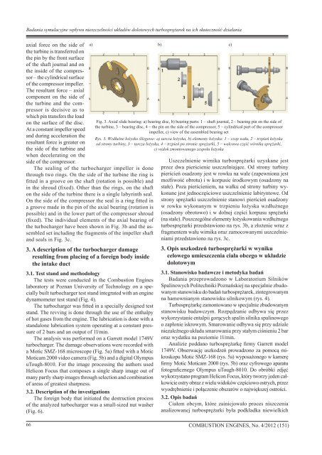
(fixed). The individual elements of the axial bearing of<br />
the turbocharger have been shown in Fig. 3b and the assembled<br />
set including the fragments of the impeller shaft<br />
and seals in Fig. 3c.<br />
3. A description of the turbocharger damage<br />
resulting from placing of a foreign body inside<br />
the intake duct<br />
a) b) c)<br />
3.1. Test stand and methodology<br />
The tests were conducted in the Combustion Engines<br />
laboratory at Poznan University of Technology on a specially<br />
built turbocharger test stand integrated with an engine<br />
dynamometer test stand (Fig. 4).<br />
The turbocharger was fitted in a specially designed test<br />
stand. The revving is done through the use of the enthalpy<br />
of hot gases from the engine. The lubrication is done with a<br />
standalone lubrication system operating at a constant pressure<br />
of 2 bars and an output of 1l/min.<br />
The analysis was performed on a Garrett model 1749V<br />
turbocharger. The damage observations were recorded with<br />
a Motic SMZ-168 microscope (Fig. 5a) fitted with a Motic<br />
Moticam 2000 video camera (Fig. 5b) and a digital Olympus<br />
uTough-8010. For the image processing the authors used<br />
Helicon Focus that composes a single sharp image out of<br />
many partly sharp images through selection and combination<br />
of areas of greatest sharpness.<br />
3.2. Description of the investigations<br />
The foreign body that initiated the destruction process<br />
of the analyzed turbocharger was a small-sized nut washer<br />
(Fig. 6).<br />
Fig. 3. Axial slide bearing: a) bearing disc, b) bearing parts: 1 – shaft journal, 2 – bearing pin on the side of<br />
the turbine, 3 – bearing disc, 4 – the pin on the side of the compressor, 5 – cylindrical part of the compressor<br />
impeller, c) view of the assembled bearing set<br />
Rys. 3. Wzdłużne łożysko ślizgowe: a) tarcza łożyska, b) elementy łożyska: 1 – czop wału, 2 – trzpień łożyska<br />
od strony turbiny, 3 – tarcza łożyska, 4 – trzpień po stronie sprężarki, 5 – walcowa część wirnika sprężarki,<br />
c) widok zmontowanego zespołu łożyska<br />
Uszczelnienie wirnika turbosprężarki uzyskane jest<br />
przez dwa pierścienie uszczelniające. Od strony turbiny<br />
pierścień osadzony jest w rowku na wale (zapewniona jest<br />
możliwość obrotu) i w korpusie środkowym (osadzony na<br />
stałe). Poza pierścieniem, na wałku od strony turbiny wykonane<br />
jest jednoczęściowe uszczelnienie labiryntowe. Od<br />
strony sprężarki uszczelnienie stanowi pierścień osadzony<br />
w rowku wykonanym w trzpieniu łożyska wzdłużnego<br />
(osadzony obrotowo) i w dolnej części korpusu sprężarki<br />
(na stałe). Poszczególne elementy łożyskowania wzdłużnego<br />
turbosprężarki przedstawiono na rys. 3b, a złożenie wraz z<br />
fragmentem wału wirnika oraz zamocowanymi uszczelnieniami<br />
przedstawiono na rys. 3c.<br />
3. Opis uszkodzeń turbosprężarki w wyniku<br />
celowego umieszczenia ciała obcego w układzie<br />
dolotowym<br />
3.1. Stanowisko badawcze i metodyka badań<br />
Badania przeprowadzono w Laboratorium Silników<br />
Spalinowych Politechniki Poznańskiej na specjalnie zbudowanym<br />
stanowisku do badań turbosprężarek, zintegrowanym<br />
na hamownianym stanowisku silnikowym (rys. 4).<br />
Turbosprężarkę zamontowano w specjalnie zbudowanym<br />
stanowisku badawczym. Rozpędzanie odbywa się przez<br />
wykorzystanie entalpii gorących spalin silnika spalinowego<br />
o zapłonie iskrowym. Smarowanie odbywa się przy udziale<br />
niezależnego układu smarowania przy stałym ciśnieniu 2 bar<br />
oraz wydatku na poziomie 1l/min.<br />
Analizie poddano turbosprężarkę firmy Garrett model<br />
1749V. Obserwację uszkodzeń prowadzono za pomocą mikroskopu<br />
Motic SMZ-168 (rys. 5a) wyposażonego w kamerę<br />
firmy Motic Moticam 2000 (rys. 5b) oraz cyfrowego aparatu<br />
fotograficznego Olympus uTough-8010. Do obróbki zdjęć<br />
wykorzystano program Helicon Focus, który tworzy jeden całkowicie<br />
ostry obraz z wielu widoków częściowo ostrych, przez<br />
wyodrębnienie i połączenie obszarów o największej ostrości.<br />
3.2. Opis badań<br />
Ciałem obcym, które zainicjowało proces niszczenia<br />
analizowanej turbosprężarki była podkładka niewielkich<br />
66 <strong>COMBUSTION</strong> <strong>ENGINES</strong>, No. 4/2012 (151)