Chapter 12 Assembly Modeling-I
Chapter 12 Assembly Modeling-I
Chapter 12 Assembly Modeling-I

Create successful ePaper yourself
Turn your PDF publications into a flip-book with our unique Google optimized e-Paper software.
<strong>Assembly</strong> <strong>Modeling</strong>-I <strong>12</strong>-37<br />
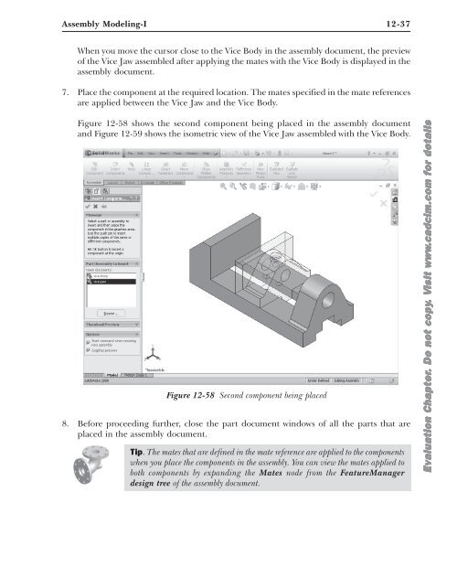
When you move the cursor close to the Vice Body in the assembly document, the preview<br />
of the Vice Jaw assembled after applying the mates with the Vice Body is displayed in the<br />
assembly document.<br />
7. Place the component at the required location. The mates specified in the mate references<br />
are applied between the Vice Jaw and the Vice Body.<br />
Figure <strong>12</strong>-58 shows the second component being placed in the assembly document<br />
and Figure <strong>12</strong>-59 shows the isometric view of the Vice Jaw assembled with the Vice Body.<br />
Figure <strong>12</strong>-58 Second component being placed<br />
8. Before proceeding further, close the part document windows of all the parts that are<br />
placed in the assembly document.<br />
Tip. The mates that are defined in the mate reference are applied to the components<br />
when you place the components in the assembly. You can view the mates applied to<br />
both components by expanding the Mates node from the FeatureManager<br />
design tree of the assembly document.<br />
Evaluation <strong>Chapter</strong>. Do not copy. Visit www.cadcim.com for details