MIL-DTL-26500, Pyle® Connectors - Amphenol.ru
MIL-DTL-26500, Pyle® Connectors - Amphenol.ru
MIL-DTL-26500, Pyle® Connectors - Amphenol.ru

Create successful ePaper yourself
Turn your PDF publications into a flip-book with our unique Google optimized e-Paper software.
<strong>Amphenol</strong><br />
Aerospace<br />
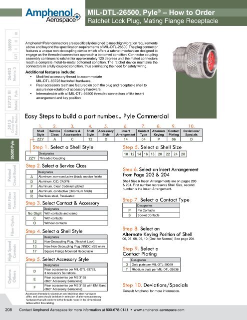
<strong>MIL</strong>-<strong>DTL</strong>-<strong>26500</strong>, Pyle ® – How to Order<br />
Ratchet Lock Plug, Mating Flange Receptacle<br />
Options High Speed<br />
EMI Filter Printed<br />
5015 83723 III 26482 38999<br />
Others<br />
Fiber Optics<br />
Transient Circuit Board<br />
<strong>26500</strong> Pyle Crimp Rear<br />
Contacts Release Matrix Matrix Pyle Matrix 2 SJT I II III<br />
208<br />
<strong>Amphenol</strong> ® /Pyle ® connectors are specifically designed to meet high vibration requirements<br />
above and beyond the specification require ments of <strong>MIL</strong>-<strong>DTL</strong>-<strong>26500</strong>. The plug connector<br />
features a unique non-decoupling device which offers a ratchet mechanism designed to<br />
engage as the threaded connectors approach a bottomed condi tion. Connector coupling<br />
assembly continues to ratchet for approxi mately 120 degrees until the mated connectors<br />
reach a complete metal-to-metal bottomed condition. The ratchet device maintains the<br />
connectors in a fully coupled condition, thus eliminating the need for safety wiring.<br />
Additional features include:<br />
• Modified accessory thread to accommodate<br />
<strong>MIL</strong>-<strong>DTL</strong>-83723 back shell hardware.<br />
• Rear accessory teeth are featured on both the plug and recepta cle shell to<br />
assure non-rotation of accessory hardware<br />
• Intermateable with all <strong>MIL</strong>-<strong>DTL</strong>-<strong>26500</strong> threaded connectors of like insert<br />
arrangement and key position<br />
Easy Steps to build a part number... Pyle Commercial<br />
ZZY<br />
1. 2. 3. 4. 5. 6. 7. 8. 9. 10.<br />
Shell Service Contacts & Shell Accessory Insert Contact Alternate Contact Deviations/<br />
Style Class Accessories Style Style Arrangement Type Keying Plating Specials<br />
ZZY A C 12 D 14 04 P 06 D<br />
Step 1. Select a Shell Style<br />
Designates<br />
Threaded Coupling<br />
Step 2. Select a Service Class<br />
A<br />
D<br />
F<br />
M<br />
R<br />
Designates<br />
Aluminum, non-conductive (black anodize finish)<br />
Aluminum, O.D. CAD/Ni<br />
Aluminum, Clear Cadmium plated<br />
Aluminum, conductive (chromium finish)<br />
Stainless steel, Passivated<br />
Step 3. Select Contact & Accessory<br />
No Digit<br />
C<br />
O<br />
Designates<br />
With contacts and clamp<br />
With contacts<br />
Without contacts<br />
Step 4. Select a Shell Style<br />
Designates<br />
12 Non-Decoupling Plug, (Ratchet Lock)<br />
13 New Non-Decoupling Plug (NNDC) (SS only)<br />
17 Square Flange Mounted Receptacle<br />
Step 5. Select Accessory Style<br />
Designates<br />
Rear accessories per <strong>MIL</strong>-<strong>DTL</strong>-83723,<br />
D<br />
3 Accessory Serrations.<br />
Rear accessories per MS 3155<br />
E<br />
(360° Accessory Serrations)<br />
Rear accessories per MS 3155 with EMI Band<br />
F<br />
(360° Accessory Serrations)<br />
Accessory threads for aluminum and stainless steel hardware<br />
differ, and care should be taken in selection of alternate accessory<br />
hardware that will conform to the threads noted in the dimensional<br />
tables within this catalog.<br />
Step 5. Select a Shell Size<br />
10 12 14 16 18 20 22 24 28<br />
Step 6. Select an Insert Arrangement<br />
from Page 203 & 204<br />
Shell Size & Insert Arrangements are on pages 203<br />
& 204. First number represents Shell Size, second<br />
number is the Insert Arrangement.<br />
Step 7. Select a Contact Type<br />
Designates<br />
Contact <strong>Amphenol</strong> Aerospace for more information at 800-678-0141 • www.amphenol-aerospace.com<br />
P<br />
S<br />
Pin Contacts<br />
Socket Contacts<br />
Step 8. Select an<br />
Alternate Keying Position of Shell<br />
06, 07, 08, 09, 10 (Omit for Normal) See page 204<br />
Step 9. Select a<br />
Contact Plating<br />
D<br />
T<br />
Designates<br />
Gold plate per <strong>MIL</strong>-<strong>DTL</strong>-39029<br />
Rhodium plate per <strong>MIL</strong>-<strong>DTL</strong>-26636<br />
Step 10. Deviations/Specials<br />
Consult <strong>Amphenol</strong> for more information.