MIL-DTL-26500, Pyle® Connectors - Amphenol.ru
MIL-DTL-26500, Pyle® Connectors - Amphenol.ru
MIL-DTL-26500, Pyle® Connectors - Amphenol.ru

You also want an ePaper? Increase the reach of your titles
YUMPU automatically turns print PDFs into web optimized ePapers that Google loves.
<strong>Amphenol</strong><br />
Aerospace<br />
Assembly Inst<strong>ru</strong>ctions for <strong>MIL</strong>-<strong>DTL</strong>-<strong>26500</strong><br />
Options High Speed<br />
EMI Filter Printed<br />
5015 83723 III 26482 38999<br />
Others<br />
Fiber Optics<br />
Transient Circuit Board<br />
<strong>26500</strong> Pyle Crimp Rear<br />
Contacts Release Matrix Matrix Pyle Matrix 2 SJT I II III<br />
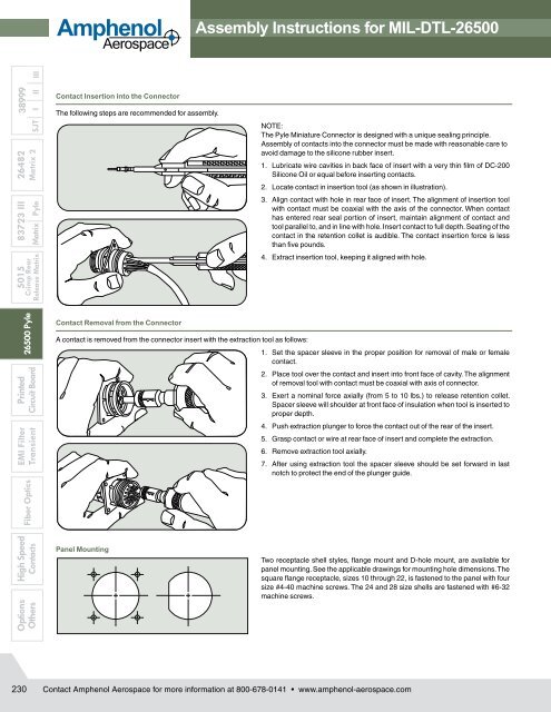
Contact Insertion into the Connector<br />
The following steps are recommended for assembly.<br />
Contact Removal from the Connector<br />
NOTE:<br />
The Pyle Miniature Connector is designed with a unique sealing principle.<br />
Assembly of contacts into the connector must be made with reasonable care to<br />
avoid damage to the silicone <strong>ru</strong>bber insert.<br />
1. Lubricate wire cavities in back face of insert with a very thin film of DC-200<br />
Silicone Oil or equal before inserting contacts.<br />
2. Locate contact in insertion tool (as shown in illustration).<br />
3. Align contact with hole in rear face of insert. The alignment of insertion tool<br />
with contact must be coaxial with the axis of the connector. When contact<br />
has entered rear seal portion of insert, maintain alignment of contact and<br />
tool parallel to, and in line with hole. Insert contact to full depth. Seating of the<br />
contact in the retention collet is audible. The contact insertion force is less<br />
than five pounds.<br />
4. Extract insertion tool, keeping it aligned with hole.<br />
A contact is removed from the connector insert with the extraction tool as follows:<br />
1. Set the spacer sleeve in the proper position for removal of male or female<br />
contact.<br />
2. Place tool over the contact and insert into front face of cavity. The align ment<br />
of removal tool with contact must be coaxial with axis of connector.<br />
3. Exert a nominal force axially (from 5 to 10 lbs.) to release retention collet.<br />
Spacer sleeve will shoulder at front face of insulation when tool is inserted to<br />
proper depth.<br />
4. Push extraction plunger to force the contact out of the rear of the insert.<br />
5. Grasp contact or wire at rear face of insert and complete the extraction.<br />
6. Remove extraction tool axially.<br />
7. After using extraction tool the spacer sleeve should be set forward in last<br />
notch to protect the end of the plunger guide.<br />
Panel Mounting<br />
Two receptacle shell styles, flange mount and D-hole mount, are available for<br />
panel mounting. See the applicable drawings for mounting hole dimensions. The<br />
square flange receptacle, sizes 10 through 22, is fastened to the panel with four<br />
size #4-40 machine screws. The 24 and 28 size shells are fastened with #6-32<br />
machine screws.<br />
230<br />
Contact <strong>Amphenol</strong> Aerospace for more information at 800-678-0141 • www.amphenol-aerospace.com