MIL-DTL-26500, Pyle® Connectors - Amphenol.ru
MIL-DTL-26500, Pyle® Connectors - Amphenol.ru
MIL-DTL-26500, Pyle® Connectors - Amphenol.ru

You also want an ePaper? Increase the reach of your titles
YUMPU automatically turns print PDFs into web optimized ePapers that Google loves.
<strong>Amphenol</strong><br />
Aerospace<br />
<strong>MIL</strong>-<strong>DTL</strong>-<strong>26500</strong>, Pyle ®<br />
Insert Arrangements Alternate Keying<br />
Options High Speed<br />
EMI Filter Printed<br />
5015 83723 III 26482 38999<br />
Others<br />
Fiber Optics<br />
Transient Circuit Board<br />
<strong>26500</strong> Pyle Crimp Rear<br />
Contacts Release Matrix Matrix Pyle Matrix 2 SJT I II III<br />
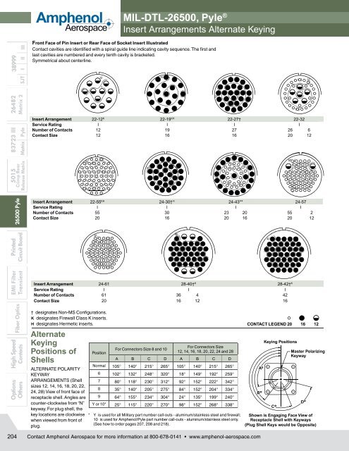
Front Face of Pin Insert or Rear Face of Socket Insert Illustrated<br />
Contact cavities are identified with a spiral guide line indicating cavity sequence. The first and<br />
last cavities are numbered and every tenth cavity is bracketed.<br />
Symmetrical about centerline.<br />
55<br />
1<br />
Insert Arrangement 22-55 KH 24-30† K 24-43** 24-57<br />
Service Rating I I I I<br />
Number of Contacts 55 30 23 20 55 2<br />
Contact Size 20 16 20 16 20 12<br />
Insert Arrangement 24-61 28-40† K 28-42† K<br />
Service Rating I I I<br />
Number of Contacts 61 36 4 42<br />
Contact Size 20 16 12 16<br />
† designates Non-MS Configurations.<br />
K designates Firewall Class K inserts.<br />
H designates Hermetic inserts.<br />
Alternate<br />
Keying<br />
Positions of<br />
Shells<br />
ALTERNATE POLARITY<br />
KEYWAY<br />
ARRANGEMENTS (Shell<br />
sizes 12, 14, 16, 18, 20, 22,<br />
24, 28) View of front face of<br />
receptacle shell. Angles are<br />
counter-clock wise from “N”<br />
keyway. For plug shell, the<br />
key locations are clock wise<br />
when viewed from front of<br />
plug.<br />
61<br />
12<br />
1<br />
1<br />
Position<br />
30<br />
19<br />
For <strong>Connectors</strong> Size 8 and 10<br />
1 1<br />
For <strong>Connectors</strong> Size<br />
12, 14, 16, 18, 20, 22, 24 and 28<br />
A B C D A B C D<br />
Normal 105° 140° 215° 265° 105° 140° 215° 265°<br />
6 102° 132° 248° 320° 18° 149° 192° 259°<br />
7 80° 118° 230° 312° 92° 152° 222° 342°<br />
8 35° 140° 205° 275° 84° 152° 204° 334°<br />
9 64° 155° 234° 304° 24° 135° 199° 240°<br />
Y or 10* 25° 115° 220° 270° 98° 152° 268° 338°<br />
* Y is used for all Military part number call-outs - aluminum/stainless steel and firewall;<br />
10 is used for <strong>Amphenol</strong>/Pyle part number call-outs - aluminum/stainless steel only.<br />
(See how to order pages 207, 208 and 218).<br />
1<br />
Insert Arrangement 22-12 K 22-19 KH 22-27† 22-32<br />
Service Rating I I I I<br />
Number of Contacts 12 19 27 26 6<br />
Contact Size 12 16 16 20 12<br />
40<br />
1<br />
27<br />
1<br />
43<br />
42<br />
CONTACT LEGEND 20 16 12<br />
B<br />
A<br />
°<br />
°<br />
C<br />
57<br />
Keying Positions<br />
°<br />
1<br />
1<br />
Master Polarizing<br />
Keyway<br />
Shown is Engaging Face View of<br />
Receptacle Shell with Keyways<br />
(Plug Shell Keys would be Opposite)<br />
1<br />
D<br />
°<br />
32<br />
204<br />
Contact <strong>Amphenol</strong> Aerospace for more information at 800-678-0141 • www.amphenol-aerospace.com