MIL-DTL-26500, Pyle® Connectors - Amphenol.ru
MIL-DTL-26500, Pyle® Connectors - Amphenol.ru
MIL-DTL-26500, Pyle® Connectors - Amphenol.ru

You also want an ePaper? Increase the reach of your titles
YUMPU automatically turns print PDFs into web optimized ePapers that Google loves.
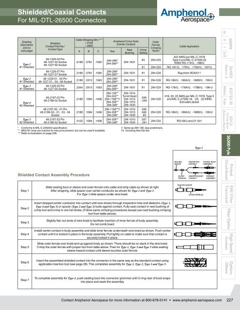
Shielded/Coaxial Contacts<br />
For <strong>MIL</strong>-<strong>DTL</strong>-<strong>26500</strong> <strong>Connectors</strong><br />
<strong>Amphenol</strong><br />
Aerospace<br />
Drawing<br />
(See below<br />
and on<br />
next page)<br />
Type 1<br />
#1 Shielded<br />
Type 2<br />
#1 Shielded<br />
Type 3<br />
#1 Shielded<br />
Type 4<br />
#2 Shielded<br />
Type 5<br />
#2 Shielded<br />
Shielded<br />
Contact Part No./<br />
Contact Type<br />
48-1226-02 Pin<br />
48-1227-02 Socket<br />
48-1227-50 Socket<br />
48-1226-57 Pin<br />
48-1227-57 Socket<br />
48-1226-51, -54 Pin<br />
48-1227-51, -54, -56 Socket<br />
48-1226-55 Pin<br />
48-1227-55 Socket<br />
48-2187-02 Pin<br />
48-2188-02 Socket<br />
48-2187-50, -51 Pin<br />
48-2188-50, -51, -53, -54<br />
Socket<br />
48-2187-52 Pin<br />
48-2188-52 Socket<br />
Cable Stripping Dim.***<br />
+.0156<br />
–.0000<br />
A B C Tool<br />
.2189 .0781 .1094<br />
.2189 .0781 .1094<br />
.2189 .0313 .1563<br />
.2344 .0313 .1563<br />
.2189 .1094 .1406<br />
.2189 .1094 .1406<br />
.3125 .1094 .1406<br />
294-268*<br />
294-289**<br />
294-268*<br />
294-289**<br />
294-268*<br />
294-289**<br />
294-268*<br />
294-289**<br />
294-126**<br />
294-243**<br />
294-1166**†<br />
294-358**<br />
294-268*<br />
294-1166**†<br />
294-358**<br />
294-268*<br />
294-358**<br />
294-268*<br />
<strong>Amphenol</strong> Crimp Tools<br />
(Center Contact)<br />
Nest<br />
Bushing<br />
294-1631<br />
Crimp<br />
Setting<br />
Outer<br />
Fer<strong>ru</strong>le<br />
Crimping<br />
Tool††<br />
Cable Application<br />
#3 294-529<br />
#22 AWG per <strong>MIL</strong>-C-7078<br />
Type II and <strong>MIL</strong>-C-27500-22<br />
KING RG-174/U, -188/U<br />
#1 294-529 RG-161/U, -179/U, -179A/U, -187/U<br />
294-1631 #1 294-528 Raychem 9530A11<br />
294-1631 #1 294-528 RG-180/U, -180A/U, -180B/U, -195/U<br />
294-1631 #1 294-529 RG-178/U, -178A/U, -178B/U, -196-U<br />
294-1014<br />
Turret Head<br />
294-1014<br />
294-1015<br />
299-1630<br />
294-1014<br />
294-1015<br />
294-1630<br />
294-1015<br />
294-1630<br />
.030<br />
-.040<br />
.030<br />
.040<br />
#3<br />
.037<br />
-.041<br />
294-528<br />
* Conforms to <strong>MIL</strong>-C-22520/2 specification. † Same as 294-126, less positioners.<br />
** MS3191 tools are inactive for new procurement, but can be used if available. †† Including Hex Die Set<br />
*** Refer to illustration on page 228.<br />
Shielded Contact Assembly Procedure<br />
Step 1<br />
Step 2<br />
Step 3<br />
Step 4<br />
Step 5<br />
Slide sealing boot or sleeve and outer fer<strong>ru</strong>le onto cable and strip cable as shown at right.<br />
After stripping, slide spacer over center conductor as shown for Type 2 and Type 3.<br />
For Type 3 slide spacer under wire braid.<br />
Insert stripped center conductor into contact until wire shows through inspection hole and dielectric (Type 1,<br />
Type 4 and Type 5) or spacer (Type 2 and Type 3) butts against contact. Fully seat contact in nest bushing of<br />
crimp tool and crimp in one full stroke. (Follow same crimping procedures except use nest bushing crimping<br />
tool from table above).<br />
Slightly flair out ends of wire braid to facilitate insertion of inner fer<strong>ru</strong>le of body assembly.<br />
Do not comb braid.<br />
Install center contact in body assembly and slide inner fer<strong>ru</strong>le underneath wire braid as shown. Push center<br />
contact until it is locked in place in the body assembly. Pull lightly on cable to make sure that contact is<br />
securely locked in place.<br />
Slide outer fer<strong>ru</strong>le over braid and up against body as shown. There should be no slack in the wire braid.<br />
Crimp the outer fer<strong>ru</strong>le with proper tool from table above. Then for Type 1, Type 3 and Type 5 slide sealing<br />
sleeve toward contact until sleeve touches outer fer<strong>ru</strong>le.<br />
#18, 20, 22 AWG per <strong>MIL</strong>-C-7078, Type II<br />
and <strong>MIL</strong>-C-27500-18, -20, -22 KING<br />
Ext<strong>ru</strong>ded Jacket<br />
294-528 RG-180/U, -180A/U, -180B/U, -195/U<br />
294-530 RG-59/U and 21-541<br />
SEALING<br />
SLEEVE<br />
OUTER<br />
FERRULE<br />
Type 1<br />
CENTER PIN<br />
CONTACT<br />
CENTER SOCKET<br />
CONTACT<br />
SOCKET BODY<br />
ASSEMBLY<br />
SEALING CENTER PIN SOCKET BODY<br />
SEALING SEALING CENTER CENTER PIN PIN SOCKET SOCKET BODY BODY<br />
SEALING SLEEVE CONTACT ASSEMBLY<br />
SLEEVE SLEEVE<br />
CENTER<br />
CONTACT<br />
PIN<br />
SOCKET<br />
ASSEMBLY<br />
BODY<br />
SLEEVE CONTACT ASSEMBLY<br />
PIN BODY<br />
ASSEMBLY<br />
OUTER CENTER SOCKET PIN BODY<br />
OUTER OUTER CENTER CENTER SOCKET SOCKETPIN PIN BODY BODY<br />
OUTER FERRULE<br />
SEALING SLEEVE CONTACT<br />
ASSEMBLY<br />
FERRULE<br />
CENTER<br />
CONTACT<br />
SOCKET<br />
PIN BODY<br />
ASSEMBLY<br />
FERRULE CONTACT<br />
ASSEMBLY<br />
SEALING SLEEVE<br />
SEALING SEALING SLEEVE SLEEVE<br />
SEALING SLEEVE<br />
OUTER FERRULE<br />
OUTER FERRULE<br />
OUTER OUTER FERRULE<br />
OUTER FERRULE<br />
38999<br />
III II I SJT<br />
26482 83723 III 5015<br />
Matrix 2<br />
Matrix Pyle<br />
Crimp Rear<br />
Release Matrix<br />
<strong>26500</strong> Pyle<br />
Printed<br />
Circuit Board<br />
EMI Filter<br />
Transient<br />
Fiber Optics<br />
High Speed<br />
Contacts<br />
Step 6<br />
Step 7<br />
Insert the assembled shielded contact into the connector in the same way as the standard contact using<br />
applicable insertion tool (see page 28). This completes assembly for Type 1, Type 2, Type 3 and Type 5.<br />
To complete assembly for Type 4, push sealing boot into connector grommet until O-ring riser of boot snaps<br />
into place and seals the assembly.<br />
Options<br />
Others<br />
Contact <strong>Amphenol</strong> Aerospace for more information at 800-678-0141 • www.amphenol-aerospace.com<br />
227