62-10627A - Sunbelt Transport Refrigeration
62-10627A - Sunbelt Transport Refrigeration
62-10627A - Sunbelt Transport Refrigeration
You also want an ePaper? Increase the reach of your titles
YUMPU automatically turns print PDFs into web optimized ePapers that Google loves.
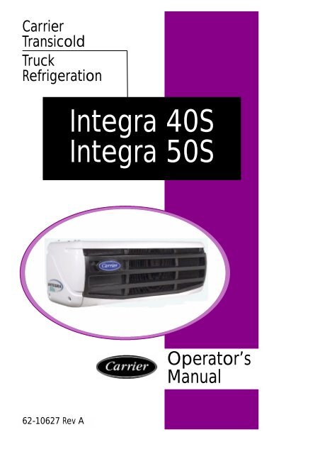
Carrier<br />
Transicold<br />
Truck<br />
<strong>Refrigeration</strong><br />
Integra 40S<br />
Integra 50S<br />
Operator’s<br />
Manual<br />
<strong>62</strong>-10<strong>62</strong>7 Rev A
OPERATOR’S<br />
MANUAL<br />
TRUCK<br />
REFRIGERATION UNIT<br />
Integra 40S<br />
Integra 50S<br />
Carrier Transicold,<br />
A member of the United Technologies Corporation family. Stock symbol UTX.<br />
Carrier Transicold Division, Carrier Corporation,<br />
P.O. Box 4805, Syracuse, N.Y. 13221 U. S. A.<br />
Carrier Corporation 2003 D Printed in U. S. A. 0703
Integra 40/50s OPERATOR’S MANUAL<br />
This guide has been prepared for the operator of Carrier Transicold<br />
truck refrigeration units. It contains basic instructions for the daily<br />
operation of the refrigeration unit as well as safety information, and<br />
other information that will help you to deliver the load in the best<br />
possible condition. Please take the time to read the information<br />
contained in this booklet and refer to it whenever you have a<br />
question about the operation of your Carrier Transicold Integra<br />
40/50s unit.<br />
Your refrigeration unit has been engineered to provide long,<br />
trouble-free performance when it is properly operated and<br />
maintained. A comprehensive maintenance program will help to<br />
insure that the unit continues to operate reliably. Such a<br />
maintenance program will also help to control operating costs,<br />
increase the unit’s working life, and improve performance.<br />
This guide is intended as an introduction to your unit and to provide<br />
general assistance when needed. More comprehensive<br />
information can be found in the Operation and Service Manual for<br />
your unit. This manual can be obtained from your Carrier Transicold<br />
dealer.<br />
When having your unit serviced, be sure to specify genuine Carrier<br />
Transicold replacement parts for the highest quality and best<br />
reliability.<br />
At Carrier Transicold, we are continually working to improve the<br />
products that we build for our customers. As a result, specifications<br />
may change without notice.
CONTENTS<br />
Page<br />
Safety .................................... 1<br />
Unit Identification .......................... 2<br />
Symbols used on Cab Control ............... 4<br />
Unit Operation ............................ 5<br />
Product Loading ........................... 13<br />
Recommended <strong>Transport</strong> Temperatures ...... 14<br />
Problems & Alarms ........................ 15<br />
Standby Operation Guidelines ............... 19<br />
Fuses .................................... 20<br />
Unit Maintenance .......................... 22<br />
Emergency Road Service ................... 24
SAFETY<br />
Your Carrier Transicold refrigeration unit has been designed with<br />
the safety of the operator in mind. During normal operation, all<br />
moving parts are fully enclosed to help prevent injury. During all<br />
pre-trip inspections, daily inspections, and problem<br />
troubleshooting, you may be exposed to moving parts; please stay<br />
clear of all moving parts when the unit is in operation.<br />
WARNING<br />
Beware of unannounced starting of the<br />
fans caused by the thermostat and the<br />
start/stop cycling of the unit.<br />
REFRIGERANTS<br />
The refrigerant contained in the refrigeration system of your unit<br />
can cause frostbite, severe burns, or blindness when in direct<br />
contact with the skin or eyes. For this reason, and because of<br />
legislation regarding the handling of refrigerants during system<br />
service, we recommend that, whenever your unit requires service<br />
of the refrigeration system, you contact your nearest Carrier<br />
Transicold authorized repair facility for service.<br />
EMERGENCY SWITCH<br />
D The unit can be completely<br />
shut down manually by the<br />
emergency switch inside the<br />
frame of the condenser unit.<br />
The emergency switch has<br />
to be reinitiated to allow the<br />
unit to restart with the “ON”<br />
key of the cab command.<br />
Emergency Switch<br />
1
UNIT IDENTIFICATION<br />
Integra 40S/50S unit is identified by a nameplate attached to the<br />
frame of the unit. This nameplate identifies the complete model<br />
number of the unit, the serial number, the refrigerant charge and<br />
quantity, and the date the unit was placed in service.<br />
If a problem occurs, please refer to the information on this plate,<br />
and make a note of the model and serial number before calling for<br />
assistance. This information will be needed when you contact a<br />
technician or Carrier Transicold Service Engineer so that he or she<br />
may properly assist you.<br />
nameplate<br />
2
A : Evaporator<br />
B : Condenser<br />
C : Cab control<br />
D : Compressor mounting kit<br />
E : Vehicle battery<br />
F : Standby plug<br />
G : Main road fuse<br />
A<br />
B<br />
C<br />
G<br />
F<br />
E<br />
D<br />
3
SYMBOLS USED ON CAB CONTROL<br />
Readout<br />
Standby operation display<br />
Road operation display<br />
Manual defrost control key<br />
Unit start-up key<br />
Unit shut-down key<br />
Data selection key<br />
Selected data decrement key<br />
Selected data increment key<br />
Unit operation display<br />
S Green = in-range (left half)<br />
S Red = malfunction (right half)<br />
4
UNIT OPERATION<br />
OPERATING PRINCIPLE<br />
After starting up the refrigeration unit by pressing the ON key on the<br />
Cab Command, unit start--up and shut--down are automatic.<br />
S<br />
On Road operation, an open--type compressor is driven by<br />
the engine of the vehicle. The vehicle battery powers the<br />
evaporator and condenser fans. The unit automatically shuts<br />
down when the engine is switched off with the ignition key.<br />
S<br />
On Standby, a standby compressor is energized, and a<br />
transformer is used to power the evaporator and condenser<br />
fans. The power network connection is detected by the Cab<br />
Command which automatically starts up the unit in Standby<br />
mode.<br />
S<br />
If the ignition key is switched on while the unit is connected to<br />
the power network, or vice--versa, the Cab Command triggers<br />
a visual alarm, in the form of a flashing red malfunction light<br />
and readout. In this case, the unit will start in road operating<br />
mode.<br />
As soon as one operating mode is inhibited, the unit<br />
automatically starts up in the other mode.<br />
S<br />
In all cases the unit can be completely shut down manually by<br />
pressing the OFF key on the Cab Command.<br />
5
STARTING - ENGINE OPERATION<br />
1. Press ON key.<br />
(Start-up is time delayed<br />
for 40 seconds)<br />
2. Check if box temperature is displayed.<br />
3. Check if road operation light is on.<br />
NOTE: If standby power cord is plugged<br />
in, the unit will run in standby mode.<br />
6
STARTING - STANDBY OPERATION<br />
1. Press the OFF key and<br />
plug in power supply.<br />
2. Press the ON key.<br />
(Start-up is time delayed for<br />
40 seconds)<br />
3. Check that the standby operation light is on.<br />
7
TEMPERATURE SETPOINT<br />
1. Press SET key<br />
2. Press + (plus) key to<br />
increase setpoint or<br />
press -- (minus) key to<br />
decrease setpoint.<br />
3. Press SET key when desired setpoint<br />
is displayed to lock in new setpoint.<br />
8
MANUAL DEFROST<br />
2. Press Manual Defrost key to initiate<br />
manual defrost.<br />
STOPPING UNIT<br />
1. Check that box temperature is<br />
40_F or lower.<br />
1. Press the OFF key.<br />
9
DEFROST INTERVAL<br />
Defrost interval in hours: 1H, 2H, 3H, 4H, 5H & 6H<br />
AUT: microprocessor optimized automatic defrost according to<br />
type of cargo.<br />
1. Press the OFF key.<br />
2. Press Defrost and ON key to display the<br />
previously selected defrost interval.<br />
3. Press -- (minus) or + (plus) key to select<br />
defrost interval.<br />
4. Press SET key to validate modified value.<br />
10
CHANGING DISPLAY BRIGHTNESS<br />
1. Press ON key.<br />
2. Press within 5 seconds the + (plus) or -- (minus)<br />
key to increase or decrease display brightness..<br />
11
MINIMUM/MAXIMUM SETPOINT, OUT-OF-<br />
RANGE AND CONTINUOUS AIRFLOW<br />
Minimum Setpoint Settings: 32_F (0_C) or --20_F (--29_C)<br />
Maximum Setpoint Settings: 68_F (20_C) or 86_F (30_C)<br />
Out-of-Rang Settings: 1, 2 or 3_C (3.6, 5.4 or 7.2_F)<br />
Continuous Airflow Settings: F/ON or F/OFF<br />
1. Turn unit on and Press + (plus) key.<br />
2. Press -- (minus) key.<br />
3. Press Defrost key.<br />
4. Check that the ! light flashes green.<br />
5. The operator can select a Minimum Setpoint. The<br />
selections are 32_F (0_C) or --20_F (--29_C). Press<br />
+ (plus) key or -- (minus) key to change setting.<br />
6. Press SET key to save setting. Next Maximum<br />
Setpoint setting will appear.<br />
7. Press + (plus) key to increase Maximum Setpoint<br />
setting. Press -- (minus) key to decrease setting.<br />
8. Press SET key to save Maximum Setpoint setting.<br />
9. Next setting is Out-of-Range. Press + (plus) key to<br />
increase Out-of-Range setting. Press -- (minus) key<br />
to decrease setting.<br />
10. Next setting is Continuous Airflow. This is selectable<br />
to fan on or fan off at setpoint. Press +<br />
(plus) or -- (minus) key to select desired operating<br />
mode. Press SET key to save fan mode setting .<br />
12
PRODUCT LOADING<br />
BEFORE LOADING:<br />
D Pre-cool the body. This will remove much of the heat from the<br />
inside of the body, and give the product better protection when<br />
it is loaded.<br />
D Place the unit in a defrost cycle immediately before loading. This<br />
will remove moisture accumulated on the evaporator coil.<br />
DURING LOADING:<br />
D Turn the unit off!<br />
D Check product temperature during loading.<br />
D Ensure that the air return and supply opening remain<br />
unobstructed.<br />
D Leave approximately 4 to 5 inches between the load and the<br />
front wall for air return to the unit.<br />
D Leave at least 10 to 12 inches between the top of the load and<br />
the ceiling to ensure that there is nothing to prevent airflow to<br />
the rear of the body<br />
D Load product on pallets to provide free air return to unit and<br />
improve product protection.<br />
Proper air circulation in the truck body, air that can move around<br />
and through the load, is a critical element in maintaining product<br />
quality during transport. If air cannot circulate completely around<br />
the load, hot spots or top-freeze can occur.<br />
The use of pallets is highly recommended. Pallets, when loaded so<br />
air can flow freely through the pallets to return to the evaporator,<br />
help protect the product from heat passing through the floor of the<br />
truck. When using pallets, it is important to refrain from stacking<br />
extra boxes on the floor at the rear of the truck, this will cut off the<br />
airflow.<br />
Product stacking is another important factor in protecting the<br />
product. Products that generate heat -- fruits and vegetables, for<br />
example -- should be stacked so the air can flow through the product<br />
to remove the heat; this is called “air stacking” the product.<br />
Products that do not create heat -- meats and frozen products --<br />
should be stacked tightly in the center of the trailer.<br />
13
All products should be kept away from the side-walls of the body,<br />
to allow air flow between the body and the load; this prevents heat<br />
filtering through the walls from affecting the product.<br />
It is important to check the temperature of the product being loaded<br />
to ensure that it is at the correct temperature for transport. The<br />
refrigeration unit is designed to maintain the temperature of the<br />
product at the temperature at which it was loaded; it was not<br />
designed to cool warm product.<br />
RECOMMENDED TRANSPORT<br />
TEMPERATURES<br />
Below are some general recommendations on product transport<br />
temperatures and operating modes for the unit. These are included<br />
for reference only and should not be considered preemptive of the<br />
set point required by the shipper or receiver.<br />
More detailed information can be obtained from your Carrier<br />
Transicold dealer.<br />
Product<br />
14<br />
Setpoint Range<br />
_F _C<br />
Bananas 56 to 58 13 to 14<br />
Fresh fruits and vegetables 33 to 38 0.5to3<br />
Fresh meats and seafood 28 to 32 --2to0<br />
Dairy Products 33 to 38 0.5to3<br />
Ice* 15 to 20 -- 10 to -- 7<br />
Frozen fruits and vegetables* -- 10 to 0 -- 23 to -- 18<br />
Frozen meats and seafood* -- 10 to 0 -- 23 to -- 18<br />
Ice Cream* -- 20 to -- 15 -- 29 to -- 26<br />
During delivery cycles that include frequent stops and door<br />
openings, it is recommended that the unit be turned off during the<br />
time the body doors are open to help conserve the product<br />
temperature.<br />
* Variations may be necessary for very high or very low ambient<br />
temperatures. 1.
PROBLEMS & ALARMS<br />
Everything possible has been done to ensure that your unit is the<br />
most reliable, trouble-free equipment available today. If, however<br />
you run into problems the following section may be of assistance.<br />
If you do not find the trouble that you have experienced listed,<br />
please call your Carrier Transicold dealer for assistance.<br />
Unit won’t power<br />
up.<br />
Unit won’t start.<br />
Unit won’t run.<br />
Unit shut down.<br />
Unit not cooling<br />
properly.<br />
General Problems<br />
Check battery condition.<br />
Check battery connections.<br />
Check all fuses<br />
Check all fuses<br />
Check all fuses<br />
Check alarm codes.<br />
Check minimum setpoint setting (see page 12).<br />
Defrost unit.<br />
Check evaporator for airflow restriction.<br />
Check condenser for airflow restriction.<br />
Check body for damage or air leaks.<br />
Check product is loaded properly<br />
Check refrigerant charge.<br />
15
ALARM DISPLAY<br />
1. When an Alarm is activated,<br />
the ! light flashes red.<br />
The ! light flashes green<br />
when the unit is operating<br />
correctly.<br />
2. Press the SET key for 5 seconds to<br />
display alarms.<br />
3. Press + or -- key to view additional alarms.<br />
4. Press SET key to return to box temperature display.<br />
NOTE: There are two types of Alarms<br />
Axx (example: A02)<br />
Pxx (example: P02)<br />
Axx -- Designates Active Alarms<br />
Pxx -- Designates Past Alarms, These are Alarm<br />
conditions that existed but are now not active.<br />
16
ALARM LIST<br />
ALARM<br />
A00<br />
A01<br />
A02<br />
A03<br />
A04<br />
A05<br />
A06<br />
A07<br />
A08<br />
A09<br />
A10<br />
A11<br />
A12<br />
A13<br />
A14<br />
A15<br />
A16<br />
A17<br />
A18<br />
A19<br />
A20<br />
A21<br />
A22<br />
A23<br />
A24<br />
A25<br />
A26<br />
A27<br />
A28<br />
EE<br />
bAt<br />
- - -<br />
- - -<br />
- - -<br />
Err<br />
- - -<br />
No Malfunction<br />
Low Pressure Switch Open<br />
High Pressure Switch Open<br />
ALARM DESCRIPTION<br />
Standby Compressor Over Heated<br />
Road Compressor Clutch<br />
Standby Contactor (high amps draw)<br />
Condenser Fan Motor (high amps draw)<br />
Fan Speed Alarm<br />
Hot Water Solenoid (high amps draw)<br />
Hot Gas Valve HGS1 (high amps draw)<br />
Liquid Injection Valve (high amps draw)<br />
Condenser Closing Valve HGS2<br />
Out-of-Range High Temperature<br />
Out-of-Range Low Temperature<br />
Defrost Cycle >45 minutes<br />
Setpoint out of range --20_F to86_F<br />
Drain Water Resistor -- Heater (DWR1)<br />
Standby Compressor or Diode Overload<br />
Electrical Heating Relay (high amps draw)<br />
Liquid Solenoid Valve (high amps draw)<br />
Standby Low Pressure Switch Open<br />
Compressor Contactor Open<br />
Condenser Fan Motor Open Circuit<br />
Hot Water Solenoid Open Circuit<br />
Hot Gas Valve (HGS1) Open Circuit<br />
Liquid Injection Valve Open Circuit<br />
Hot Gas Valve (HGS2) Open Circuit<br />
Drain Water Resistor (DWR1) Open Circuit<br />
Heating Relay (EHR) Open Circuit<br />
Return Air Sensor<br />
Low Battery Voltage<br />
Using Road & Standby Compressors at the Same Time.<br />
Programming mistake of maximum setpoint by user.<br />
Setpoint lower than maximum setpoint but in the range<br />
-- 20_F to86_F<br />
17
ALARM RESET<br />
1. Press the OFF key to clear Active Alarm<br />
list. Unit can now be restarted if no<br />
Active Alarm condition remains.<br />
18
STANDBY OPERATION GUIDELINES<br />
For safe, reliable operation in Standby mode, it is important to<br />
follow a few guidelines:<br />
D<br />
D<br />
Always check that the unit is OFF (Cab Command) before<br />
connecting or disconnecting the unit from power source.<br />
The circuit breaker and power cord used for Standby<br />
operation must comply with legislation currently applicable<br />
on site of use and with unit specifications in table below.<br />
Unit Operating Voltage<br />
Maximum Unit<br />
Operating Amperage<br />
Integra 40S<br />
230V / Single phase / 60 hz 24 A<br />
230V / Three phase / 60 hz 14 A<br />
Integra 50S<br />
230V / Single phase / 60 hz 25 A<br />
230V / Three phase / 60 hz 15 A<br />
Voltage<br />
Power Cord Length and Wire Gage<br />
25 ft 50 ft 75 ft 100 ft<br />
230/1/60<br />
208/1/60<br />
12 10 10 8<br />
230/3/60 16 14 12 10<br />
D When multiple units are in use, each unit must be operated<br />
on its own electrical circuit. You should never operate more<br />
than one unit on a circuit breaker.<br />
Important note: This information is provided as a guideline only.<br />
When preparing a circuit for operation of the refrigeration unit, a<br />
licensed electrician should be contracted. A licensed electrician is<br />
familiar with all local ordinances and special requirements for your<br />
area and can ensure that the circuits are properly designed,<br />
installed, and connections are correct.<br />
19
FUSES<br />
To access the road and standby fuses, remove the left side cover<br />
(fastened by 4 screws).<br />
Note: See Fuse Table<br />
for Item Number<br />
2<br />
1<br />
Item<br />
Purpose<br />
230/60 hz<br />
3ph<br />
230/60 hz<br />
1ph<br />
1 Road Supply Fuse 50 A 50 A<br />
2 Standby Supply Fuse (a) 50 A 50 A<br />
3 Main Standby Fuse FB (x3) (b) 16 A 12 A<br />
4 Main Standby Fuse FB (x3) (c) 20 A 16 A<br />
5 Heating Resistor Fuses F4/F5/F6 6.3 A 3.15 A<br />
6 Transformer Primary Fuses F1/F2/F3 3.15 A 2A<br />
7 Main Road Fuse (d) 60 A 60 A<br />
(a) On road / standby unit only<br />
(b) If located in standby box<br />
(c) If located in standby plug (not shown)<br />
(d) Not shown -- this fuse is located close to the vehicle battery (12 v).<br />
20
To access the fuses in the control box, remove the left side cover,<br />
then open the control box (fastened by 4 screws).<br />
With Electrical Heating Option<br />
5<br />
6<br />
Without Electrical heating Option<br />
3<br />
6<br />
21
UNIT MAINTENANCE<br />
WARNING<br />
Before working on unit, check that:<br />
D the unit (cab command) is OFF.<br />
D<br />
it is impossible for unit to automatically start-up during<br />
maintenance.<br />
Refrigerant Charge: R404A<br />
6 lbs Integra 40S<br />
6.5 lbs Integra 50S<br />
Compressor oil<br />
Oil Charge<br />
Approved Oil<br />
Road<br />
Standby<br />
Mobil Arctic EAL 68 250cc (.53 pint) 1200cc (2.5 pint)<br />
For the most reliable operation and for maximum life, your unit<br />
requires regular maintenance. Maintenance should be performed<br />
on the following schedule:<br />
Hours 100 1000 2000 3000 4000 5000 6000 7000<br />
Service A H H H H H H H H<br />
Service B H H H H H H H<br />
Service C H H H<br />
Service D<br />
H<br />
22
SERVICE A<br />
SERVICE B<br />
SERVICE C<br />
SERVICE D<br />
Service Schedule<br />
S Check the tension of the alternator belt(s).<br />
S Check that the vehicle engine runs correctly<br />
at low speed and that the compressor kit is<br />
correctly tightened/belt tension.<br />
S Check the tightness of bolts and screws and<br />
that the unit is correctly fastened onto the box.<br />
S Clean the condenser and the evaporator.<br />
S Replace the Road compressor belt.<br />
S Replace the filter--drier.<br />
S Clean the TXV orifice filter.<br />
S Check the standby compressor oil level.<br />
S Check the operation of the cab control.<br />
S Check the defrost<br />
- Cut -in,<br />
- Fan shut -down,<br />
- Cut -out,<br />
- Defrost water drain.<br />
S Check the water tighness of the emergency<br />
switch cap.<br />
S Check the bearings of the belt tension pulleys<br />
and bearing of the mechanics kit. Change the<br />
spring if there is one.<br />
S Change the shockmounts (if any) installed on<br />
the road compressor mounting kit.<br />
S Check the operation of the evaporator and<br />
condenser fans. Change the condenser motor<br />
brushes.<br />
S Change the compressor oil. Only use Ester oil<br />
(POE) approved by CARRIER. See the<br />
technical information sheets for the<br />
recommended quantities and types of oil.<br />
S Change the removable fuses and capacitor (if<br />
any) in the control box.<br />
Note : The evaporator of this unit is equipped with brushless fan<br />
motors which don’t need to be maintained.<br />
23
EMERGENCY ROAD SERVICE<br />
At Carrier Transicold we’re working hard to give you complete<br />
service when and where you need it. That means a worldwide<br />
network of dealers that offer 24-hour emergency service. These<br />
service centers are manned by factory trained service personnel<br />
and backed by extensive parts inventories that will assure you of<br />
prompt repair.<br />
Should you experience a unit problem with your refrigeration unit<br />
during transit, follow your company’s emergency procedure or<br />
contact the nearest Carrier Transicold service center. Consult the<br />
Shortstop Service Centers directory to locate the service center<br />
nearest you. This directory may be obtained from your Carrier<br />
Transicold dealer.<br />
If you are unable to reach a Service Center, call our<br />
24-hour Action Line: (800)448-1661<br />
When calling, please have the following information ready for<br />
fastest service:<br />
S<br />
S<br />
S<br />
S<br />
Your name, the name of your company, and your location.<br />
A telephone number where you can be called back.<br />
<strong>Refrigeration</strong> unit model number and serial number.<br />
Box temperature, set point and product.<br />
Brief description of the problem you are having, and what you have<br />
already done to correct the problem.<br />
We will do everything we can to get your problem taken care of and<br />
get you back on the road.<br />
24
Index<br />
A<br />
Alarm Display, 16<br />
Alarm List, 17<br />
Alarm Reset, 18<br />
C<br />
Changing Display Brightness, 11<br />
Continuous Airflow, 12<br />
D<br />
Defrost Interval, 10<br />
E<br />
Emergency Road Service, 24<br />
Emergency Switch, 1<br />
Fuses, 20<br />
F<br />
M<br />
Manual Defrost, 9<br />
Minimum/Maximum Setpoint, 12<br />
O<br />
Operating principle, 5<br />
Out--of--Range, 12<br />
P<br />
Problems, 15<br />
Product Loading, 13<br />
R<br />
Recommended <strong>Transport</strong><br />
Temperatures, 14<br />
Refrigerants, 1<br />
S<br />
Safety, 1<br />
Setpoint, 8<br />
Standby Operation Guidelines,<br />
19<br />
Starting -- Engine Operation, 6<br />
Starting -- Standby Operation, 7<br />
Stopping Unit, 9<br />
Symbols used on Cab Control, 4<br />
T<br />
Temperature Setpoint, 8<br />
U<br />
Unit Identification, 2<br />
Unit Maintenance, 22<br />
Unit Operation, 5<br />
Index -1


