vector 1800 mt - Sunbelt Transport Refrigeration
vector 1800 mt - Sunbelt Transport Refrigeration
vector 1800 mt - Sunbelt Transport Refrigeration
- No tags were found...

Create successful ePaper yourself
Turn your PDF publications into a flip-book with our unique Google optimized e-Paper software.
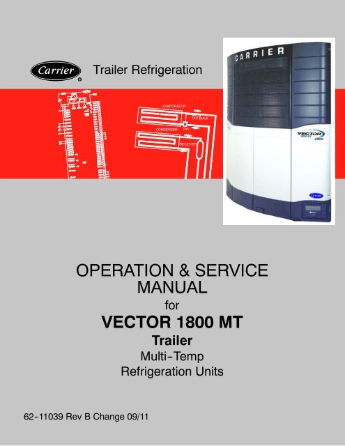
RTrailer <strong>Refrigeration</strong>EVAPORATORTXV BULBCONDENSERTXVRECEIVEROPERATION & SERVICEMANUALforVECTOR <strong>1800</strong> MTTrailerMulti--Temp<strong>Refrigeration</strong> Units62--11039 Rev B Change 09/11
TABLE OF CONTENTSPARAGRAPH NUMBERPageSAFETY PRECAUTIONS ..................................................................... 1-11.1 SAFETY PRECAUTIONS ............................................................. 1-11.2 SPECIFIC WARNING AND CAUTION STATEMENTS ..................................... 1-11.3 SAFETY DECALS .................................................................... 1-5UNIT DESCRIPTION .......................................................................... 2-12.1 INTRODUCTION ..................................................................... 2--12.2 GENERAL DESCRIPTION ............................................................. 2--22.3 CONDENSING SECTION ............................................................. 2--72.3.1 Condenser Coil ................................................................... 2--72.3.2 Engine ........................................................................... 2--72.3.3 Compressor ...................................................................... 2--72.3.4 Filter Drier ........................................................................ 2--92.3.5 Receiver ......................................................................... 2--92.3.6 Transducers and Sensors .......................................................... 2--102.4 COMPARTMENT 1 EVAPORATOR SECTION ............................................ 2--102.4.1 Electronic Expansion Valve (EVXV) .................................................. 2--102.4.2 Heat Exchanger ................................................................... 2--102.4.3 Evaporator Coil ................................................................... 2--102.4.4 Transducers and Sensors .......................................................... 2--102.5 REMOTE EVAPORATOR(S) ........................................................... 2--112.6 SYSTEM OPERATING CONTROLS AND COMPONENTS ................................. 2--112.6.1 Multiple Languages ................................................................ 2--112.6.2 Special Features .................................................................. 2--112.6.3 Microprocessor Component Description And Location .................................. 2--122.7 ELECTRONIC MODULES ............................................................. 2--182.7.1 Overload Ground Fault Module (OGF) ............................................... 2--182.7.2 Phase Reversal Module (PRM) ..................................................... 2--182.8 OPTIONS2.8.1 Light Bar ......................................................................... 2--182.8.2 Door Switch(es) ................................................................... 2--182.8.3 Out of Range Alarm ............................................................... 2--192.8.4 Remote Control Panel ............................................................. 2--192.9 ENGINE DATA ....................................................................... 2--202.10 ENGINE AIR SYSTEM ................................................................ 2--202.11 COMPRESSOR DATA ................................................................ 2--212.12 REFRIGERATION SYSTEM DATA ...................................................... 2--212.13 ELECTRICAL DATA ................................................................... 2--222.14 COMPONENT RESISTANCE & CURRENT DRAW ....................................... 2--232.15 SAFETY DEVICES ................................................................... 2--232.16 REFRIGERANT CIRCUIT DURING COOLING ........................................... 2--242.17 REFRIGERANT CIRCUIT -- HEATING AND DEFROSTING ................................ 2--24i 62--11039
TABLE OF CONTENTS (Continued)PARAGRAPH NUMBERPageOPERATION ................................................................................. 3-13.1 RS “ON” AND ALL COMPARTMENT SWITCHES “OFF” ................................... 3--13.2 STARTING UNIT -- ENGINE/ROAD OPERATION ......................................... 3--23.3 STARTING UNIT -- ELECTRIC STANDBY OPERATION ................................... 3--33.4 Unit Startup -- Engine/Road and Electric Standby ......................................... 3--53.5 PRETRIP ............................................................................ 3--63.6 CHANGING SETPOINT ............................................................... 3--93.7 START--STOP OPERATION -- ENGINE/ROAD AND ELECTRIC STANDBY .................. 3--103.8 CONTINUOUS RUN OPERATION ...................................................... 3--113.9 SLEEP MODE ON .................................................................... 3--123.10 SLEEP MODE OFF ................................................................... 3--133.11 MANUAL DEFROST .................................................................. 3--153.11.1 Manual Defrost ................................................................... 3--153.12 TRIP START ......................................................................... 3--163.13 VIEW ACTIVE ALARMS ............................................................... 3--173.14 VIEW INACTIVE ALARMS ............................................................. 3--183.15 UNIT DATA .......................................................................... 3--193.16 VIEW HOURMETERS ................................................................. 3--233.17 FUNCTIONAL CHANGE (PARAMETERS) ............................................... 3--243.18 LANGUAGE SELECTION ............................................................. 3--293.19 STOPPING UNIT ..................................................................... 3--303.20 DATA RECORDING ................................................................... 3--313.20.1 Microprocessor Information ......................................................... 3--313.20.2 Data Recording ................................................................... 3--313.20.3 Sensor & Event Data .............................................................. 3--313.20.4 Data Downloading ................................................................. 3--323.20.5 Data Recorder Power--Up .......................................................... 3--323.21 OPTIONS ........................................................................... 3--333.21.1 IntelliSet ......................................................................... 3--333.21.2 Remote Control Panel ............................................................. 3--3662--11039ii
TABLE OF CONTENTS (Continued)PARAGRAPH NUMBERPageTEMPERATURE CONTROL ................................................................... 4-14.1 SYSTEM START--UP ................................................................. 4--14.2 START--STOP OPERATION ........................................................... 4--24.3 CONTINUOUS RUN OPERATION ...................................................... 4--44.4 TEMPERATURE CONTROL ........................................................... 4--44.4.1 COOL MODE ........................................................................ 4--44.4.2 PULSE COOL MODE ................................................................. 4--54.4.3 PRIORITY MODES ................................................................... 4--54.4.4 SUPPLY AIR LIMIT CONTROL ......................................................... 4--64.4.5 HEAT MODE ......................................................................... 4--74.4.6 NULL MODE ......................................................................... 4--74.4.7 UNLOADERS ........................................................................ 4--74.4.8 SPEED CONTROL ................................................................... 4--84.4.9 DEFAULT MODE ..................................................................... 4--84.4.10DEFROST OPERATION ............................................................... 4--84.5 Temperature Range Lock 1 & 2 ..................................................... 4--104.6 ProductShieldt ........................................................................ 4--124.6.1 Modes ............................................................................ 4--124.6.2 Temperature Ranges ................................................................ 4--134.7 OUTPUT OVERRIDES ................................................................ 4--164.7.1 Speed Control Solenoid (SCS) Overrides ............................................. 4--164.7.2 Unloader Control Overrides ......................................................... 4--174.7.3 Suction Pressure Operation ........................................................ 4--19iii 62--11039
PARAGRAPH NUMBERTABLE OF CONTENTS (Continued)TECHNICIAN INTERFACE ..................................................................... 5-15.1 PC MODE/DOWNLOAD PORT ......................................................... 5--15.2 MICROPROCESSOR CONFIGURATION AND TECHNICIAN TEST MODES ................ 5--2Page5.2.1 Configuration Mode ................................................................ 5--35.2.2 Component Test Mode ............................................................. 5--125.2.3 Service Mode ..................................................................... 5--145.3 DOWNLOADING DATA WITH THE PC CARD ............................................ 5--155.4 INSTALLING NEW SOFTWARE ........................................................ 5--165.4.1 Using The Program PC Card ....................................................... 5--165.4.2 Using MicroProgrammer ........................................................... 5--175.4.3 Troubleshooting Software Loading Problems .......................................... 5--175.5 SETTING PM (PREVENTATIVE MAINTENANCE) HOURMETERS ......................... 5--185.6 ADVANCE MICROPROCESSOR REPLACEMENT & CONFIGURATION SETUP ............. 5--195.6.1 Microprocessor Replacement ....................................................... 5--195.6.2 Microprocessor Setup .............................................................. 5--205.6.3 Configurations Via Keypad ......................................................... 5--205.6.4 Functional Parameters Via Keypad .................................................. 5--215.6.5 DataRecorder Via ReeferManager PC Program ....................................... 5--215.6.6 Engine And Switch--on Hour Meters Via ReeferManager PC Program .................... 5--215.6.7 Configuration/IntelliSet Card ........................................................ 5--225.6.8 Microprocessor Final Checkout ..................................................... 5--22MESSAGECENTER ........................................................................... 6-16.1 MessageCenter Messages ............................................................. 6-1ALARM TROUBLESHOOTING ................................................................. 7-17.1 INTRODUCTION TO ALARM TROUBLESHOOTING ...................................... 7-17.2 NOTES ............................................................................... 7-27.3 DRIVER/OPERATOR ALARMS ............................................................. 7-31 LOW FUEL LEVEL WARNING ....................................................... 7---32 LOW ENGINE OIL LEVEL ........................................................... 7---43 LOW COOLANT LEVEL ............................................................. 7 --- 57.4 SHUTDOWN ALARMS .................................................................... 7-611 LOW ENGINE OIL PRESSURE ....................................................... 7---612 HIGH COOLANT TEMPERATURE .................................................... 7---713 HIGH DISCHARGE PRESSURE ...................................................... 7---814 ELECTRICAL CIRCUIT .............................................................. 7 --- 915 BATTERY VOLTAGE TOO HIGH ..................................................... 7---1016 BATTERY VOLTAGE TOO LOW ...................................................... 7---1117 HIGH COMP DISCHARGE TEMP ..................................................... 7---1218 LOW REFRIGERANT PRESSURE .................................................... 7---1319 LOW FUEL SHUTDOWN. ............................................................ 7---1420 MAXIMUM COMPRESSOR ALARMS ................................................. 7---1421 TECHNICIAN RESET REQUIRED .................................................... 7---1522 LOW SUCTION SUPERHEAT ......................................................... 7---1523 A/C CURRENT OVER LIMIT ......................................................... 7---1623 A/C CURRENT OVER LIMIT ......................................................... 7---1727 HIGH SUCTION PRESSURE .......................................................... 7---1928 CHECK REFRIGERATION SYSTEM .................................................. 7---2062--11039 ivChange 09/11
TABLE OF CONTENTS (Continued)PARAGRAPH NUMBERPage7.5 START UP/ENGINE ALARMS .............................................................. 7-2130 FAILED TO RUN MINIMUM TIME ................................................... 7---2131 FAILED TO START --- AUTO MODE ................................................... 7 --- 2234 ENGINE FAILED TO STOP ........................................................... 7---23335 CHECK STARTER CIRCUIT .......................................................... 7---2436 CHECK COOLANT TEMPERATURE .................................................. 7---2537 CHECK LOW SPEED RPM ........................................................... 7---2638 CHECK HIGH SPEED RPM ........................................................... 7---2739 CHECK ENGINE RPM ............................................................... 7 --- 2840 CHECK GLOW PLUGS ............................................................... 7 --- 2941 ENGINE STALLED .................................................................. 7 --- 307.6 WARNING / STATUS ALARMS ............................................................. 7 -3251 ALTERNATOR NOT CHARGING ..................................................... 7---3253 BOX TEMP OUT --- OF --- RANGE ....................................................... 7 --- 3354 DEFROST NOT COMPLETE .......................................................... 7---3455 CHECK DEFROST AIR SWITCH ...................................................... 7---3559 DATALOGGER NOT RECORDING ................................................... 7---3660 DATALOGGER TIME WRONG ....................................................... 7---3762 C2 BOX TEMP OUT --- OF --- RANGE .................................................... 7 --- 3863 C3 BOX TEMP OUT --- OF --- RANGE .................................................... 7 --- 407.7 ELECTRICAL ALARMS ................................................................... 7-4271 BADF2ORF3FUSE ................................................................. 7 --- 4273 NO POWER --- CHECK POWER CORD ................................................. 7 --- 4375 COMP MOTOR OVERLOAD ......................................................... 7---4476 CONDENSER MOTOR OVERHEATED ................................................ 7---4577 EVAP MOTOR OVERHEATED ....................................................... 7---4683 CHECK REMOTE DEFROST LIGHT .................................................. 7---4684 CHECK REMOTE ALARM LIGHT .................................................... 7---4785 CHECK UL1 CIRCUIT ............................................................... 7 --- 4786 CHECK UL2 CIRCUIT ............................................................... 7 --- 4889 CHECK REMOTE AUTO LIGHT ...................................................... 7---4891 CHECK HTCON1 RELAY COIL ....................................................... 7---4992 CHECK HTCON2 RELAY COIL ....................................................... 7---4993 CHECK START UP BUZZER .......................................................... 7---5094 CHECK COMP CONTACTOR 1 ....................................................... 7---5095 CHECK CDCON RELAY COIL ........................................................ 7---5196 CHECK GENCONR RELAY COIL ..................................................... 7---5198 CHECK HIGH TEMP THERMOSTAT .................................................. 7---5299 CHECK STANDBY CONTACTOR ..................................................... 7---52100 OVERLOAD / GROUND FAULT ...................................................... 7---53101 C2 EVAP MOTOR OVERHEATED .................................................... 7---54102 C3 EVAP MOTOR OVERHEATED .................................................... 7---55103 CHECK 2HTCON1 RELAY COIL ...................................................... 7---56104 CHECK 2HTCON2 RELAY COIL ...................................................... 7---56105 CHECK 3HTCON1 RELAY COIL ...................................................... 7---57106 CHECK 3HTCON2 RELAY COIL ...................................................... 7---57107 CHECK 2LSV CIRCUIT .............................................................. 7 --- 58108 CHECK 3LSV CIRCUIT .............................................................. 7 --- 58109 CHECK 1EVCON RELAY COIL ....................................................... 7---59110 CHECK 2EVCON RELAY COIL ....................................................... 7---59111 CHECK 3EVCON RELAY COIL ....................................................... 7---60v 62--11039
TABLE OF CONTENTS (Continued)PARAGRAPH NUMBERPage7.8 SENSOR ALARMS ....................................................................... 7-61121 CHECK AMBIENT AIR SENSOR ..................................7---61122 CHECK RETURN AIR SENSOR ...................................7---61123 CHECK SUPPLY AIR SENSOR ....................................7---62124 CHECK DEFROST TERM 1 SENSOR ..............................7---62125 CHECK COMP DISCHARGE SENSOR (CDT) ......................7---63126 CHECK FUEL SENSOR CIRCUIT .................................7---63127 CHECK SUCTION TEMP SENSOR (CST) ..........................7---64128 LOW A/C AMPS .................................................7 --- 64129 CHECK ENG COOLANT SENSOR ................................7---65130 CHECK ENGINE RPM SENSOR ..................................7---66131 CHECK EVAP TEMP SENSOR ....................................7---67133 CHEEK REMOTE TEMP SENSOR 1 ...............................7---67134 CHEK REMOTE TEMP SENSOR 2 ................................7---68136 C2 CHK SUPPLY AIR SENSOR ...................................7---68137 C2 CHECK RETURN AIR SENSOR ................................7---69138 C3 CHECK RETURN AIR SENSOR ................................7---69139 C2 CHECK DEFROST SENSOR ...................................7---70140 C3 CHECK DEFROST SENSOR ...................................7---707.9 PRETRIP ALARMS ....................................................................... 7-71P141 PRE---TRIP STOPPED BY USER ...................................................... 7---71P144 CHECK UL1 CIRCUIT ............................................................... 7 --- 71P145 CHECK SPEED SOL CIRCUIT ........................................................ 7---72P146 C2 CHECK HEATER 1 CIRCUIT ...................................................... 7---73P147 C2 CHECK HEATER 2 CIRCUIT ...................................................... 7---75P151 CHECK GLOW PLUG CIRCUIT ....................................................... 7---77P152 CHECK FUEL SOLENOID CIRCUIT .................................................. 7---78P153 CHECK RETURN AIR SENSOR ....................................................... 7---79P154 CHECK SUPPLY AIR SENSOR ........................................................ 7---79P155 CHECK COOLANT TEMP SENSOR ................................................... 7---80P156 CHECK BATTERY VOLTS ............................................................ 7---80P157 CHECK BATTERY CURRENT ........................................................ 7---81P158 CHECK AMBIENT AIR SENSOR ...................................................... 7---81P159 CHECK DEFROST TERM 1 SENSOR .................................................. 7---82P160 CHECK DISCHARGE TEMP SENSOR ................................................. 7---82161 CHECK SUCTION TEMP SENSOR (CST) .............................................. 7---83P163 C3 CHECK HEATER 1 CIRCUIT ...................................................... 7---84P164 CHECK UL2 CIRCUIT ............................................................... 7 --- 86P166 C2 CHK SUPPLY AIR SENSOR ........................................................ 7---87P167 C3 CHECK HEATER 2 CIRCUIT ...................................................... 7---88P168 C2 CHECK LSV VALVE .............................................................. 7 --- 90P171 CHECK EVAP & DISC PRESS ......................................................... 7---91P174 CHECK LOW SPEED RPM ........................................................... 7---92P175 CHECK HIGH SPEED RPM ........................................................... 7---93P176 C3 CHECK LSV VALVE .............................................................. 7 --- 94P177 CHECK EVAP SUPERHEAT .......................................................... 7---94P178 CHECK UL1 ......................................................................... 7 --- 95P180 CHECK SUCTION MOD VALVE ...................................................... 7---96P184 C2 CHECK EVAP FAN MOTOR ....................................................... 7---97P185 C3 CHECK EVAP FAN MOTOR ....................................................... 7---99P186 CHECK EVAP OUTLET TEMP ........................................................ 7---10162--11039vi
TABLE OF CONTENTS (Continued)PARAGRAPH NUMBERPage7.9 PRETRIP ALARMS (Continued) ........................................................... 7 -71P187 CHECK HEATER 1 CIRCUIT ......................................................... 7---102P188 CHECK HEATER 2 CIRCUIT ......................................................... 7---104P189 CHECK EVAPORATOR FAN MOTOR ................................................. 7---106P190 CHECK CONDENSER FAN MOTOR .................................................. 7---108P191 CHECK UL2 ......................................................................... 7 --- 109P199 C2 CHECK RETURN AIR SENSOR .................................................... 7---110P206 CHECK CONDENSER FAN CIRCUIT .................................................. 7---111P207 CHK COMPRESSOR CONTACT CIRC ................................................. 7---113P208 CHK GENERATOR CONT CIRC ...................................................... 7---114P209 CHECK STANDBY CONT CIRCUIT ................................................... 7---115P210 C3 CHECK RETURN AIR SENSOR .................................................... 7---116P211 CHECK DEFROST SENSOR (2DTT) ................................................... 7---117P212 C3 CHECK DEFROST SENSOR (3DTT) ................................................ 7---1177.10 MAINTENANCE ALARMS ................................................................ 7-118223 ENGINE MAINTENANCE DUE ...................................7---118224 STANDBY MAINTENANCE DUE .................................7---118225 GENERAL MAINTENANCE DUE .................................7---119226 SERVICE SOON --- PM #1 DUE ....................................7 --- 119227 SERVICE SOON --- PM #2 DUE ....................................7 --- 120228 SERVICE SOON --- PM #3 DUE ....................................7 --- 120229 SERVICE SOON --- PM #4 DUE ....................................7 --- 121230 SERVICE SOON --- PM #5 DUE ....................................7 --- 1217.11 MICROPROCESSOR ALARMS ............................................................ 7 -122232 SETPOINT ERROR .................................................................. 7 --- 122233 MODEL # ERROR .................................................................. 7 --- 122234 UNIT SERIAL # ERROR ............................................................. 7---123235 CONTROL SERIAL # ERROR ........................................................ 7---123236 TRAILER ID # ERROR .............................................................. 7---124237 FUNCTION PARAMETERS ERROR ................................................... 7---124238 CONFIGURATIONS 1 ERROR ........................................................ 7---125239 CONFIGURATIONS 2 ERROR ........................................................ 7---125240 HOUR METER ERROR .............................................................. 7---126241 ALARM STATUS ERROR ............................................................ 7---126242 DIS PRESS CALIBRATE ERROR ...................................................... 7---127243 SUCTION/EVAP CALIBRATE ERROR ................................................. 7---127245 MICRO SW REV ERROR ............................................................. 7---128246 EEPROM WRITE FAILURE .......................................................... 7---128247 CONFIGURATIONS 3 ERROR ........................................................ 7---129248 CONFIGURATION MODE / HP2 ERROR .............................................. 7---129249 MICROPROCESSOR ERROR ......................................................... 7---130vii 62--11039
TABLE OF CONTENTS (Continued)PARAGRAPH NUMBERPageSERVICE .................................................................................... 8-18.1 MAINTENANCE SCHEDULE .......................................................... 8--18.2 PRETRIP INSPECTION ............................................................... 8--38.3 PRIMING FUEL SYSTEM ............................................................. 8--48.3.1 Mechanical Fuel Pump ............................................................. 8--48.4 SERVICING FUEL PUMP ............................................................. 8--58.4.1 Mechanical Pump ................................................................. 8--58.4.2 Electrical Pump ................................................................... 8--58.5 FUEL LEVEL SENSOR ................................................................ 8--58.6 ENGINE SERVICE AND COMPONENTS ................................................ 8--78.6.1 Engine RPM Setup ................................................................ 8--78.6.2 Cooling System ................................................................... 8--78.6.3 Testing The RPM Sensor ........................................................... 8--88.6.4 Lube Oil Filters ................................................................... 8--88.6.5 Servicing The Speed Control Solenoid And Linkage .................................... 8--98.6.6 Engine Air Cleaner ................................................................ 8--98.6.7 Engine Crankcase Breather ........................................................ 8--98.6.8 Servicing Glow Plugs .............................................................. 8--108.6.9 Water Pump V--Belt ............................................................... 8--108.7 EVAPORATOR HEATERS ............................................................. 8--118.7.1 Description ....................................................................... 8--118.7.2 Replacing Heaters ................................................................. 8--118.7.3 Compartment One Evaporator Blower and Motor ...................................... 8--118.7.4 Condenser Fan And Motor Assemblies ............................................... 8--128.8 BATTERY CHARGER ................................................................. 8--128.8.1 Description ....................................................................... 8--128.8.2 Checking Battery Charger .......................................................... 8--128.9 GENERATOR ........................................................................ 8--138.9.1 Description ....................................................................... 8--138.9.2 Preventive Maintenance and Operating Precautions ................................... 8--138.9.3 Generator Removal ................................................................ 8--148.9.4 Generator Assembly Procedure ..................................................... 8--168.10 REMOTE COMPARTMENT LSVs ...................................................... 8--188.10.1CHECKING OPERATION OF C2 LSV AND C3 LSV AND EVXV ......................... 8--188.11 PUMPING UNIT DOWN OR REMOVING REFRIGERANT CHARGE ........................ 8--198.11.1 Pumping Down The Low Side ....................................................... 8--198.11.2 Removing The Refrigerant Charge: Use Micro “EVAC MODE” ........................... 8--208.12 REFRIGERANT LEAK CHECKING: Use Micro “EVAC MODE” ............................. 8--208.13 EVACUATION AND CHARGING: Use Micro “EVAC MODE” ................................ 8--208.13.2 Preparation ....................................................................... 8--208.13.3 Procedure For Evacuation .......................................................... 8--208.13.4 Adding Refrigerant To System (Full Charge) .......................................... 8--228.14 ADDING REFRIGERANT TO SYSTEM (PARTIAL CHARGE) ........................... 8--2262--11039viii
TABLE OF CONTENTS (Continued)PARAGRAPH NUMBERPage8.15 COMPRESSOR -- MODEL 06D ........................................................ 8--238.15.1 Removal and Replacement of Compressor ........................................... 8--238.15.2 Compressor Disassembly .......................................................... 8--248.15.3 Compressor Reassembly ........................................................... 8--248.15.4 Compressor Oil Level .............................................................. 8--258.16 COMPRESSOR UNLOADER VALVE .................................................... 8--268.17 CHECKING AND REPLACING FILTER-DRIER ........................................... 8--288.18 ELECTRONIC EXPANSION VALVE ..................................................... 8--288.18.1 Replacing Expansion Valve & Screen ................................................ 8--288.18.2 EVXV coil ........................................................................ 8--298.19 THERMOSTATIC EXPANSION VALVES (REMOTE COMPARTMENTS) ..................... 8--298.19.1 Replacing Expansion Valve & Screen ................................................ 8--298.19.2 To Measure Superheat ............................................................. 8--308.20 CHECKING AND REPLACING HIGH PRESSURE CUTOUT SWITCH (HPS) ................. 8--308.20.1 Replacing High Pressure Switch ..................................................... 8--308.20.2 Checking High Pressure Switch ..................................................... 8--318.21 DISCHARGE PRESSURE TRANSDUCER (CDP) ......................................... 8--318.21.1 Calibrating Compressor Discharge Pressure Transducer ................................ 8--328.21.2 Testing Compressor Discharge Pressure Transducer ................................... 8--328.21.3 Replacing Compressor Discharge Pressure Transducer ................................ 8--338.22 COMPRESSOR SUCTION PRESSURE TRANSDUCER (CSP AND EVOP) .................. 8--338.22.1 Calibrating Compressor Suction Pressure Transducer .................................. 8--338.22.2 Testing Compressor Suction Pressure Transducer ..................................... 8--338.22.3 Replacing Compressor Suction Pressure Transducer .................................. 8--348.23 REPLACING RECEIVER SIGHT GLASS ASSEMBLY ..................................... 8--348.24 COMPRESSOR SUCTION MODULATION VALVE (CSMV) ................................ 8--348.24.1 Function ......................................................................... 8--348.24.2 CSMV Diagnostics ................................................................ 8--358.24.3 Replacing The SMV Power Head .................................................... 8--368.25 CHECKING DEFROST OR HEATING CYCLE ............................................ 8--368.25.1 Defrost Air Switch ................................................................. 8--368.25.2 Electronic Defrost Timer ............................................................ 8--378.26 CHECKING CALIBRATION OF DEFROST AIR SWITCH .................................. 8--378.27 EVAPORATOR COIL .................................................................. 8--378.27.1 Cleaning ......................................................................... 8--378.27.2 Coil Replacement -- Compartment 1 ................................................. 8--378.28 CONDENSER COIL .................................................................. 8--388.28.1 Coil Cleaning ..................................................................... 8--388.28.2 Coil Replacement ................................................................. 8--388.29 CONTROLLER SENSOR CHECKOUT .................................................. 8--38ix 62--11039
LIST OF ILLUSTRATIONSFIGURE NUMBERPageFigure 2-1 Front View ....................................................................... 2--3Figure 2-2. Front View ....................................................................... 2--4Figure 2-3 Evaporator Section -- Grille Removed ................................................ 2--5Figure 2-4 Control Box ...................................................................... 2--6Figure 2-5 Compressor Cylinder Head Unloaded ................................................ 2--8Figure 2-6 Compressor Cylinder Head Loaded .................................................. 2--9Figure 2-7 Control Module ................................................................... 2--13Figure 2-8 Display And Keypad ............................................................... 2--15Figure 2-9 OGF Module ..................................................................... 2--18Figure 2-10 PRM Phase Reversal Module ....................................................... 2--18Figure 2-11 Refrigerant Circuit All Compartments Cooling ......................................... 2--25Figure 2-12 Refrigerant Circuit -- Compartment One Cooling, Compartments 2 & 3 Heating ............ 2--26Figure 2-13 Refrigerant Circuit -- Compartments One And Two Cooling, Compartment 3 Heating ....... 2--27Figure 2-14 Refrigerant Circuit -- Compartments One And Three Cooling, Compartment 2 Heating ...... 2--28Figure 2-15 Refrigerant Circuit -- All Compartments Heating ....................................... 2--29Figure 4--1 Auto Start Sequence .............................................................. 4--1Figure 4--2 Continuous Run Frozen Temperature Control ......................................... 4--14Figure 4--3 Start/Stop Frozen Temperature Control .............................................. 4--14Figure 4--4 Continuous Run Perishable Temperature Control ..................................... 4--15Figure 4--5 Start/Stop Perishable Temperature Control ........................................... 4--15Figure 4--6 Evaporator Pressure Chart ......................................................... 4--18Figure 4--7 <strong>Refrigeration</strong> System Suction Pressures Unloading (Heat and Defrost Only) .............. 4--19Figure 8--1 Priming Fuel Pump ................................................................ 8--4Figure 8--2 Mechanical Fuel Pump ............................................................ 8--5Figure 8--3 Electric Fuel Pump (Optional) ....................................................... 8--5Figure 8--4 Fuel Level Sensor Wiring .......................................................... 8--6Figure 8--5 Fuel System Diagram ............................................................. 8--8Figure 8--6 Lube Oil Flow Diagram ............................................................ 8--8Figure 8--7 Speed Control Solenoid ............................................................ 8--9Figure 8--8 Engine Crankcase Breather ........................................................ 8--9Figure 8--9 Water Pump V--Belt ............................................................... 8--10Figure 8--10 Evaporator fan bolts ............................................................... 8--12Figure 8--11 Battery Charger ................................................................... 8--12Figure 8--12 Generator Removal ............................................................... 8--14Figure 8--13 Generator Removal ............................................................... 8--14Figure 8--14 Generator Removal ............................................................... 8--14Figure 8--15 Generator Removal ............................................................... 8--14Figure 8--16 Generator Removal ............................................................... 8--15Figure 8--17 Generator Removal ............................................................... 8--15Figure 8--18 Generator Removal ............................................................... 8--16Figure 8--19 Generator Assy ................................................................... 8--16Figure 8--20 Bolt Hole Pattern For Bell Housing and Crankshaft .................................... 8--17Figure 8--21 Vacuum Pump Connection ......................................................... 8--21Figure 8--22 Compressor -- model 06D .......................................................... 8--23Figure 8--23 Exploded view of valve plate ........................................................ 8--24xi 62--11039
LIST OF ILLUSTRATIONS (Continued)FIGURE NUMBERPageFigure 8--24 Suction valve & positioning springs .................................................. 8--24Figure 8--25 Compressor oil pump end view ..................................................... 8--25Figure 8--26 Oil Level in Sight Glass ............................................................ 8--26Figure 8--27 Unloader solenoid valve ........................................................... 8--27Figure 8--28 Solenoid Coil Replacement ......................................................... 8--27Figure 8--29 Electronic expansion valve ......................................................... 8--28Figure 8--30 Electronic expansion valve ......................................................... 8--29Figure 8--31 Thermostatic Expansion Valve Bulb and Thermocouple ................................ 8--30Figure 8--32 Typical Setup for Testing High Pressure Switch ....................................... 8--31Figure 8--33 Pressure Transducer Values ........................................................ 8--31Figure 8--34 Suction modulation valve (CSMV) ................................................... 8--34Figure 8--35 CSMV Coil (Bi--Polar Design) ....................................................... 8--35Figure 8--36 Defrost Air Switch Test Setup ...................................................... 8--37LIST OF TABLESTABLE NUMBERPageTable 2-1 Model Chart ....................................................................... 2--1Table 2-2 Compartment Configurations ........................................................ 2--1Table 2-3 Additional Support Manuals ......................................................... 2--2Table 2-4 Field Effect Transistors ............................................................. 2--14Table 2-5 Engine Data ....................................................................... 2--20Table 2-6 Compressor Data .................................................................. 2--21Table 2-7 Component Resistance & Current Draw ............................................... 2--23Table 3-1 Unit Data ......................................................................... 3--20Table 3-2 Functional Parameters .............................................................. 3--25Table 4-1 Glow Time ........................................................................ 4--2Table 4-2 Battery Voltages ................................................................... 4--2Table 8-1 Maintenance Schedule ............................................................. 8--1Table 8-2 Blower wheels identification ......................................................... 8--11Table 8-3 Compressor Torque Values .......................................................... 8--26Table 8-4 Suction and discharge Pressure Transducer Voltages ................................... 8--31Table 8-5 Compressor Discharge Pressure Transducer .......................................... 8--32Table 8-6 Compressor Suction Pressure Transducer ............................................. 8--33Table 8-7 CSMV Connections ................................................................ 8--34Table 8-8 Sensor Resistance (ATT, 1RAT, 2RAT, 3RAT, 1SAT, ENCT, EVOT, CST, 1DTT, 2DTT) ....... 8--38Table 8-9 Sensor Resistance (CDT) ........................................................... 8--39Table 8-10 Temperature Pressure Chart ........................................................ 8--4162--11039xii
SECTION 1SAFETY PRECAUTIONS1.1 SAFETY PRECAUTIONSYour Carrier Transicold refrigeration unit has beendesigned with the safety of the operator in mind. Duringnormal operation, all moving parts are fully enclosed tohelp prevent injury. During all pre-trip inspections, dailyinspections, and problem troubleshooting, you may beexposed to moving parts. Please stay clear of all movingparts when the unit is in operation and when the unitmain power switch is in the START/RUN position.CAUTIONUnder no circumstances should anyone attemptto repair the Logic or Display Boards.Should a problem develop with these component,contact your nearest Carrier Transicolddealer for replacement.CAUTIONUnder no circumstances should a technicianelectrically probe the processor at anypoint, other than the connector terminalswhere the harness attaches. Microprocessorcomponents operate at different voltagelevels and at extremely low current levels.Improper use of voltmeters, jumperwires, continuity testers, etc. could permanentlydamage the processor.CAUTIONMost electronic components are susceptibleto damage caused by electrical staticdischarge (ESD). In certain cases, the humanbody can have enough static electricityto cause resultant damage to the componentsby touch. This is especially true of theintegrated circuits found on the truck/trailermicroprocessor.Auto-StartYour refrigeration unit is equipped with Auto-Start inboth Start--Stop and Continuous Run modes. The unitmay start at any time when the Start/Run--Off Switch(SROS) is in the Start/Run position. A buzzer will soundfor 5 seconds before the unit is started. Whenperforming any check of the refrigeration unit (e.g.,checking the belts, checking the oil), make certain thatthe SROS is in the OFF position.Engine CoolantThe engine is equipped with a pressurized coolingsystem. Under normal operating conditions, the coolantin the engine and radiator is under high pressure and isvery hot. Contact with hot coolant can cause severeburns. Do not remove the cap from a hot radiator. If thecap must be removed, do so very slowly in order torelease the pressure without spray.RefrigerantsThe refrigerant contained in the refrigeration system ofyour unit can cause frostbite, severe burns, or blindnesswhen in direct contact with the skin or eyes. For thisreason, and because of legislation regarding thehandling of refrigerants during system service, werecommend that whenever your unit requires service ofthe refrigeration system you contact your nearestCarrier Transicold authorized repair facility for service.BatteryThis unit is equipped with a lead-acid type battery. Thebattery normally vents small amounts of flammablehydrogen gas. Do not smoke when checking the battery.A battery explosion can cause serious physical harmand/or blindness.1.2 SPECIFIC WARNING AND CAUTIONSTATEMENTSTo help identify the label hazards on the unit and explainthe level of awareness each one carries, an explanationis given with the appropriate consequences:DANGER -- warns against an immediate hazard whichWILL result in severe personal injury or death.WARNING -- warns against hazards or unsafe conditionswhich COULD result in severe personal injury ordeath.CAUTION -- warns against potential hazard or unsafepractice which could result in minor personal injury, orproduct or property damage.The statements listed below are specifically applicableto this refrigeration unit and appear elsewhere in thismanual. These recommended precautions must be understoodand applied during operation and maintenanceof the equipment covered herein.1--1 62-11039
WARNINGBe aware of HIGH VOLTAGE supplied by thegenerator as the unit may startautomatically. Before servicing the unit,make sure the START/RUN -OFF switch is inthe OFF position. Also disconnect thenegative battery cable. NEVERdis -assemble the generator: HIGHMAGNETIC FIELD INSIDE!WARNINGUnder no circumstances should ether orany other starting aids be used to start engine.WARNINGWhen performing service and/or maintenanceprocedures, make certain the unitis disconnected from the power sourceand that the RS is in OFF position so thatit is impossible for the unit to start up automaticallyduring the maintenance operation.WARNINGMake sure the power plug is clean and drybefore connecting to any electrical outlet/-receptacle.WARNINGDo not connect to any electrical outletwithout checking that it meets the460/3/60 and 30 Amp electrical requirements.WARNINGAlways place RS in the OFF position andturn off the high voltage power supply beforedisconnecting the high voltage powerplug from the unit.WARNINGDo not place the Start/Run -OFF Switch(RS) in the Start/Run position or the unit willstart.WARNINGDo Not Allow Jumper Wire To Touch AnyGround.WARNINGVoltage will be applied to high voltage components(i.e. the fan motor contactor) andthose components will operate (i.e. the fanblades will turn) when those componentsare energized and the unit is in standby operationand using component test mode.WARNINGCarefully protect eyes from solvent.WARNINGDo not direct water or steam into the generatoropenings. Do not allow any soap andwater solutions to enter the generator.WARNINGHigh voltage (dielectric) testing must not beperformed to the machine without first observingNEMA rules. The insulation of thisgenerator winding may be safely checkedby using a megohm meter. A high readingindicates good insulation.62-110391--2
WARNINGRelieve internal pressure of replacementcompressor by slightly loosening the boltsof both service valve flanges/blank valvepads and then lightly tapping the center ofthe valve flanges/pads with a soft mallet tobreak the seal.WARNINGDo not use a nitrogen cylinder without apressure regulator. Cylinder pressure isapproximately 159.9 Bars (2350 PSIG). Donot use oxygen in or near a refrigerant systemas an explosion may occur. (SeeFigure 8 -32)WARNINGThe Compressor Discharge PressureTransducer does not have a Schrader valvein the connecting fitting. Any dischargepressure remaining in the compressor willbe released when removing the CDP.WARNINGCarrier Transicold does not recommend allowingthe compressor to pull less than 0Bar/PSIG at any time.CAUTIONService Mode MUST be used whenever removingrefrigerant charge, refrigerant leakchecking or evacuating.CAUTIONThe display and MessageCenter may behavedifferently during the software loadingprocess, depending on the version of softwarecurrently in the controller. DO NOT IN-TERRUPT THE SOFTWARE INSTALLATIONPROCESS ONCE IT HAS STARTED.CAUTIONIt is important that communications betweenthe Micro and the computer are notdisturbed during the software loading process.If using a laptop computer, turn all energysaving features off. Turn off any screensaver, or any hard drive time out settings.CAUTIONBe certain that the clock you are using is accurate.Also, some customers are locatedin different time zones from the repair location.If you know the repair location timezone, enter that time. If you don’t, enteryour current time.CAUTIONUse only Carrier Transicold approved PolyolEster Oil (POE). Buy quantities of onequart or less. When using this hygroscopicoil, immediately reseal. Do not leave containerof oil open or contamination will occur.CAUTIONUnit uses R404A and POE oil. The use of inertgas brazing procedures is mandatory forall Carrier Transicold refrigeration units;otherwise compressor failure will occur.For more information Refer to TechnicalProcedure 98-50553-00 Inert Gas Brazing1--3 62-11039
CAUTIONUse only ethylene glycol anti-freeze (withinhibitors) in system as glycol by itself willdamage the cooling system. Always addpre-mixed 50/50 anti-freeze and water to radiator/engine.Never exceed more than a60% concentration of anti-freeze. Use a lowsilicate anti-freeze meeting GM specificationsGM 6038M for standard life coolant oruse Texaco Havoline extended life coolantor any other extended life coolant which isDexcool approved and has 5/150 (5years/150,000 miles) on the label.CAUTIONWhen changing oil filters, the new filtersshould be primed (partially filled) with cleanoil if possible. If the filters are not primed,the engine may operate for a period with nooil supplied to the bearings.CAUTIONThe mica shim must be used during disassemblyof the generator from the engine.Never attempt to remove the rotor from thestator. Leave the shim in place until the generatoris re installed on the engine.CAUTIONExtreme care must be taken to ensure themanifold common connection remains immersedin oil at all times; otherwise, air andmoisture will be drawn into compressor.CAUTIONDo not vapor charge R404a systems. Onlyliquid charging through the receiver outlet(King) valve is acceptable.CAUTIONThe +5.0 VDC (terminal B) is common betweenthe Compressor Discharge PressureTransducer, the Compressor Suction PressureTransducer, and the RPM sensor. Ifthis circuit is shorted to ground (due to oneof the mentioned components being defective,or a worn wire) the MessageCenter willshow:Suction Pressure: -29.9inHg ( -1 Bar)Discharge Pressure: 0 Bar/PSIGEngine RPM: 0.62-110391--4
1.3 SAFETY DECALS1--5 62-11039
62--03957--01 High Voltage62--03958--00 Heat Warning62--60280--00 Standby Safety62-110391--6
9SECTION 2UNIT DESCRIPTION2.1 INTRODUCTIONWARNINGBe aware of HIGH VOLTAGE supplied by thegenerator as the unit may startautomatically. Before servicing the unit,make sure the START/RUN -OFF switch is inthe OFF position. Also disconnect thenegative battery cable. NEVERdis -assemble the generator: HIGHMAGNETIC FIELD INSIDE!Table 2-1. Model ChartThis manual contains operating data, electrical data andservice instructions for the Vector <strong>1800</strong>MT refrigerationsystem.Additional support manuals are listed in Table 2-3.The model/serial number plate is located inside the uniton the frame as shown in Figure 2-2.R-404AEngine SpeedModels DescriptionCompressor EngineLB KG High LowNDP33GN6HBV2 2 Comp. 19 8.306D 41cfm V2203--DI--E2B 1850 1450NDP33GN6HBV3 3 Comp. 19 8.3Table 2-2. Compartment ConfigurationsDescription Available Configurations Compartment No. Description of Configuration1 2 2200 Single Disch.2 2 2200 Dual Discharge2 Comp.3 2 1100 Single Disch.4 2 1100 Dual Disch.2 1100 Single Disch53 1100 Dual Discharge261100 Dual Discharge3271100 Single Discharge32 2200 Single Discharge3 Comp.133 1100 Single Discharge2 2200 Dual Discharge143 1100 Dual Discharge2 2200 Dual Discharge153 1100 Single Discharge2 2200 Single Discharge163 1100 Dual Discharge2--1 62-11039
Table 2-3. Additional Support ManualsManual Number Equipment Covered Type of Manual62--11038 Vector <strong>1800</strong>MT & 06D Compressor Service Parts List62--11040 Vector <strong>1800</strong>MT Operator’s Manual62--11041 Vector <strong>1800</strong>M Easy To Run62--11095 CT4-134DI-E2B Engine Parts List62--10865 CT4-134DI-E2B Engine Workshop Manual2.2 GENERAL DESCRIPTIONThe VECTOR <strong>1800</strong>MT unit is a hybrid diesel/electric,fully charged, pre-wired, refrigeration/heating“nosemount” unit used in conjunction with one or tworemote evaporators. The unit is used on insulatedtrailers to maintain cargo temperatures within very closelimits.Electrical power is supplied to the unit from a power plugor by the diesel engine / A-C generator which is drivenby the engine. The generator provides nominal480V/3Ø/60Hz power when the engine is in high speedand nominal 300V/3Ø/45Hz in low speed .The control system is a microprocessor controller. Oncethe controller is set at the desired temperature, thesystem automatically selects cooling and heating cyclesas necessary to maintain the desired temperature withinvery close limits.62-110392--2
91918117161514234567 8 9101112131.2.Fuel filterModel/Serial number nameplate3.4.BatteryBattery charger5.6.GeneratorEngine RPM (ENRPM)7.8.Lube oil filterOil drain9. Starter motor10. Lube oil fill & dipstick11.12.Engine oil pressure switch (ENOPS)Download Port13.14.Display and KeypadFuel solenoid (FS)15.16.Speed control solenoid (SCS)Control box17.18.Engine coolant temperature (ENCT)Air cleaner19. Coolant bottleFigure 2-1. Front View2--3 62-11039
21173451676981011131415121.2.Condenser/RadiatorDefrost air switch (DAS)3.4.Receiver and sight glassesShutoff (King) valve5.6.Compressor suction modulation valve (CSMV)Filter drier7.8.Compressor suction temperature (CST)Discharge pressure transducer (CDP), Highpressure switch (HP1)9. Discharge service valveFigure 2-2. Front View10.11.Front unloader solenoid valveCompressor, Compressor discharge temperature(CDT), Rear unloader solenoid, Compressorelectrical box (Located on rear of compressor)12.13.Suction service valveCompressor sight glass14.15.Suction pressure transducer (CSP)Power Supply Receptacle (PSR)16.17.Condenser fan and motorMuffler62-110392--4
914215121312311410867591.2.Evaporator fans and motorsNozzle cover3.4.Defrost termination thermostat sensor (1DTT)Evaporator Coil5.6.Drain pan heaterHeat Exchanger7.8.Remote suction and liquid linesEvaporator outlet pressure sensor (EVOPFigure 2-3. Evaporator Section - Grille Removed9.10.Return air thermistor sensor (1RAT)Electronic expansion valve (EVXV)11.12.Evaporator outlet temperature sensor (EVOT)Electric heaters13.14.Remote evaporator liquid line connectionRemote evaporator suction line connection15. Supply air temperature sensor (1SAT)2--5 62-11039
1 23416181719 2014155629713288271226252411923222110INSIDE LEFT SIDE OF BOX1.2.Compartment 2 evaporator contactor (2EVCON)Compartment 2 heater contactor 1 (2HTCON1)3.4.Compartment 2 heater contactor 2 (2HTCON2)Compartment 3 heater contactor 1 (3HTCON1)5.6.Compartment 3 heater contactor 2 (3HTCON2)Generator contactor (GENCON)7.8.Compressor contactor (CCON)Condenser motor contactor (CDCON)9.10.Compartment 1 evaporator contactor (1EVCON)Microprocessor11.12.Compartment 1 heater contactor 2 (HTCON2)(OGF)13.14.TransformerPower source contactor (PSCON)15. Power source contactor 2 (PSCON2)Figure 2-4. Control Box16.17.Compartment 3 evaporator contactor (3EVCON)Compartment 1 heater contactor 2 (HTCON2)18.19.Compartment 1 heater contactor 1 (HTCON1)Microprocessor power fuse (F6)20.21.Contactor power fuse (F9)Run control relay (RCR)22.23.Power supply contactor relay (PSCONR)Generator contactor relay (GENCONR)24. Heat contactor 1 relay evaporator 1(HTCONR1)25.26.Compressor contactor relay (CCONR)Glow plug relay (GPR)27.28.Starter solenoid relay (SSR)Main fuse (F5)29. Phase reversal module62-110392--6
92.3 CONDENSING SECTIONThe condensing section (Figure 2-2) consists of anengine--compressor drive package, condenser fan,condenser/radiator coil, refrigerant controls, piping,wiring, defrost air switch, and associated components.The drive equipment includes the engine, generator, aircleaner, muffler, coolant overflow bottle, and drive belts.<strong>Refrigeration</strong> components mounted in the condensingsection include: the compressor, defrost air switch, suctionmodulation valve, filter drier, and receiver.2.3.1 Condenser CoilThe condenser coil is of the tube in fin type and acts as aheat exchanger in which the compressed refrigerantgas is condensed into a liquid and lowered in temperature.Air movement over the condenser is provided by atwo electric motor driven fans mounted in the condensingsection.2.3.2 EngineThe engine (Refer to Section 2.9) gives excellent fueleconomy and has easy starting characteristics. It isequipped with spin-on lube oil and fuel oil filters foreasier filter changes.Engine Transducers and Sensors:a. Engine RPM Sensor (ENRPM)Provides micro with engine rpm information to bedisplayed and recorded in the data recorder. It is locatedon the front of the engine near the generator.b. Engine Oil Pressure Switch (ENOPS)This normally open switch allows the engine to operatewhen oil pressure is above 15 ¦ 3 PSIG (1.02 ¦ 0.2Bars). The switch will close and automatically stop theengine when pressure drops below 12.3 ¦ 3 PSIG (0.84Bar). There is a 15 second delay after the engine startsto allow the oil pressure to build up before themicroprocessor looks at the input from this switch. Theswitch is located on the front of the engine below the fuelsolenoid.c. Engine Oil Level Switch (ENOLS) (Optional)ENOLS sets off Alarm when oil level is low. Located onthe oil pan next to the oil fill.d. Engine Coolant Temperature Sensor (ENCT)Provides micro with engine coolant temperatureinformation to be displayed and recorded in the datarecorder . The sensor is located on the starter side ofthe engine near the #4 Injector.e. Engine Coolant Level Sensor (ENCLS)(Optional)Sets off Alarm when coolant level is low. Located in thecoolant bottle.2.3.3 CompressorThe compressor assembly includes the refrigerant compressor,suction and discharge service valves, highpressure switch, compressor discharge thermistor andthe suction and discharge pressure transducers. Thecompressor draws refrigerant gas from the evaporatorand delivers it to the condenser at an increased temperatureand pressure. The pressure is such that refrigerantheat can be absorbed by the surrounding air atambient temperatures.Compressor UnloadersThe refrigeration compressor used is a 41cfm model06D, equipped with unloaders as standard equipment.Unloaders are used as a compressor capacity control tounload the compressor during periods of reduced loads.This provides closer temperature control, reducespotential for top freezing and reduces power required tooperate the compressor; thus reducing fuelconsumption.a. Major Working Parts1. Solenoid and valve system2. Spring loaded piston type bypass control valve3. Spring loaded discharge check valve2--7 62-11039
42 35671111089121314151.2.Solenoid ValveValve Stem3.4.Gas Bypass PortSpring Guide5.6.SpringPiston7.8.Piston Bypass ValveBleed Orificeb. Unloaded OperationFigure 2-5.9.10.StrainerSuction Manifold11.12.Cylinder Discharge ValveValve Plate13.14.Cylinder Suction ValveDischarge Piston Check Valve Assembly15. Discharge ManifoldCompressor Cylinder Head UnloadedPressure from the discharge manifold (Figure 2-5, item15) passes through the strainer (9) and bleed orifice (8)to the back of the piston bypass valve (7). Unless bledaway, this pressure would tend to close the piston (6)against the piston spring (5) pressure.With the solenoid valve (1) energized the solenoid valvestem (2) will open the gas bypass port (3).Refrigerant pressure will be bled to the suction manifold(10) through the opened gas bypass port . A reduction inpressure on the piston bypass valve will take placebecause the rate of bleed through the gas bypass port isgreater than the rate of bleed through the bleed orifice (8).When the pressure behind the piston has been reducedsufficiently, the valve spring will force the piston bypassvalve back, opening the gas bypass from the dischargemanifold to the suction manifold.Discharge pressure in the discharge manifold will closethe discharge piston check valve assembly (14)isolating the compressor discharge manifold from theindividual cylinder bank manifold.The unloaded cylinder bank will continue to operate fullyunloaded until the solenoid valve control device isde-energized and the gas bypass port is closed.62-110392--8
94562 371111081291314151.2.Solenoid ValveValve Stem3.4.Gas Bypass PortSpring Guide5.6.SpringPiston7.8.Piston Bypass ValveBleed Orificec. Loaded OperationFigure 2-6.9.10.StrainerSuction Manifold11.12.Cylinder Discharge ValveValve Plate13.14.Cylinder Suction ValveDischarge Piston Check Valve Assembly15. Discharge ManifoldCompressor Cylinder Head LoadedDischarge pressure bleeds from the discharge manifold(Figure 2-6, item 15) through the strainer (9) and (8)bleed orifice to the solenoid valve stem (2) chamber andthe back of the piston bypass valve (7).With the solenoid valve (1) de-energized the solenoidvalve stem will close the gas bypass port (3).Refrigerant pressure will overcome the bypass valvespring (5) tension and force the piston (6) forwardclosing the gas bypass from the discharge manifold tothe suction manifold (10).Cylinder discharge pressure will force open thedischarge piston check valve assembly (14).Refrigerant gas will pass into the compressor dischargemanifold.The loaded cylinder bank will continue to operate fullyloaded until the solenoid valve control device isenergized and the gas bypass port is opened. Refer toSection 4.4.7 for more information on LoadedOperation.2.3.4 Filter DrierThe drier is a cylinder shell containing a drying agentand screen. It is installed in the liquid line and functionsto keep the system clean and remove moisture from therefrigerant.2.3.5 ReceiverLiquid refrigerant from the condenser drains into thereceiver. The receiver serves as a liquid reservoir whenthere are surges due to load changes in the system; as astorage space when pumping down the system and as aliquid seal against the entrance of refrigerant gas intothe liquid line.The receiver is provided with two bull’s--eye sightglasses, for the observation of liquid level, and a pressurerelief valve.2--9 62-11039
2.3.6 Transducers and Sensorsa. Compressor Suction Pressure Transducer(CSP)Provides micro with suction pressure information to bedisplayed, recorded in the data recorder and used tocontrol the refrigeration system. It cannot be calibrated.It is located near the oil pump on the compressor.b. Compressor Discharge Pressure Transducer (CDP)Provides micro with discharge pressure information tobe displayed, recorded in the data recorder and used tocontrol the refrigeration system. It can be calibrated. It islocated on the center cylinder head of the compressor.c. Compressor Discharge Temperature SensorTransducer (CDT)Provides micro with discharge temperature informationto be displayed, recorded in the data recorder and usedto control the refrigeration system. It is located on thecenter cylinder head of the compressor.d. Compressor Suction Modulation Valve (CSMV)The CSMV opens and closes as required for capacitycontrol of the refrigeration system cooling cycle. It islocated in the suction line at the exit of the evaporatorpod.e. Compressor Suction Temperature Sensor (CST)Provides micro with suction temperature information tobe displayed, recorded in the data recorder and used tocontrol the refrigeration system. It is located on thesuction line near the filter drier.f. Ambient Air Temperature Sensor (AAT)AAT is a temperature control probe which provides microwith ambient air temperature information to be displayed,recorded in the data recorder and used to controlthe refrigeration system. It is located behind thecondenser grille.2.4 COMPARTMENT 1 EVAPORATOR SECTIONThe main evaporator fits into a rectangular opening inthe upper portion of the trailer or rail car front wall. Wheninstalled, the evaporator section is located inside thisrefrigerated compartment, and the condensing sectionis outside.The main evaporator assembly consists of anevaporator coil, evaporator fan motors, electronicexpansion valve, evaporator coil heaters, heatexchanger, defrost termination sensor and supply andreturn air sensors (See Figure 2-3) and hightemperature safeties.Heating is accomplished by electric evaporator coilheaters.Automatic evaporator coil defrosting is initiated by eithersensing the air pressure drop across the coil with adifferential air switch or with the defrost timer in themicroprocessor.2.4.1 Electronic Expansion Valve (EVXV)The electronic expansion valve is an electronic devicewhich controls the flow of liquid to the evaporator accordingto changes in superheat to the refrigerant leavingthe evaporator. The expansion valve maintains arelatively constant degree of superheat in the gas leavingthe evaporator regardless of suction pressure. Thevalve has a dual function -- automatic expansion controland prevention of liquid return to the compressor.2.4.2 Heat ExchangerThe heat exchanger is of the tube in tube type connectedin the main suction line and liquid line. Within theheat exchanger, the cold suction gas is used to cool thewarm liquid refrigerant. This results in greater systemcapacity and efficiency.2.4.3 Evaporator CoilThe unit evaporator is a tube in fin type. The operation ofthe compressor maintains a reduced pressure withinthe coil. At this reduced pressure, the liquid refrigerantevaporates at a temperature sufficiently low enough toabsorb heat from the air.2.4.4 Transducers and Sensorsa. Evaporator Outlet Pressure Transducer (EVOP)Provides micro with evaporator outlet suction pressureinformation to be displayed, recorded in the datarecorder and used to control the refrigeration system. Itcannot be calibrated. It is located in the evaporatorsection near the electronic expansion valve in thesuction line.b. Evaporator High Temperature Switch (EVHTS)EVHTS is a safety switch which turns off the electricheaters if the temperature in the evaporator compartmentreaches 130°F (54.4°). It is located on the roadsideevaporator support bracket above the coil.c. Evaporator Outlet Temperature Sensor (EVOT)Provides micro with evaporator outlet suctiontemperature information to be displayed, recorded inthe data recorder and used to control the refrigerationsystem. It is located on the suction line near theelectronic expansion valve and is wrapped withinsulating tape.d. Defrost Termination Temperature Sensor (1DTT)1DTT is located on the center tube sheet of the evaporatorsection. It senses the temperature of the evaporatorand allows defrost initiation once the temperature fallsbelow 40°F (4.4°C)e. Return Air Temperature Sensor (1RAT)1RAT is a temperature control probe which providesmicro with return air temperature information to be displayed,recorded in the data recorder and used to controlthe refrigeration system. It is located on roadside ofthe return air grille.62-110392--10
f. Supply Air Temperature Sensor (1SAT)1SAT is a temperature control probe which providesmicro with supply air temperature information to be displayed,recorded in the data recorder and used to controlthe refrigeration system. It is located on the supplyair grille.2.5 REMOTE EVAPORATOR(S)The compartments of the MultiTemp system areequipped with separate evaporators.For MultiTemp remote compartment applications singleand dual air discharge evaporators are available. Theevaporators are different in size, capacity and number offans, but all work on the same principle and use thesame three-phase 45Hz to 60Hz fan assembly.The remote evaporator(s) consist of evaporator coil(s),evaporator fan motor(s), thermostatic expansionvalve(s), defrost termination sensor(s), 12V liquid linesolenoid(s), 12V water drain heater(s), evaporator coilheaters, return air and optional supply air sensor(s) andhigh temperature safeties.The bottom section of the evaporator allows easyaccess to both the electrical and refrigeration hardware.2.6 SYSTEM OPERATING CONTROLS ANDCOMPONENTSThe temperature controller is a Carrier TransicoldAdvance Microprocessor controller (Refer to Section2.6.3 and 3). Once the controller is set at the desiredtemperature, the unit will operate automatically tomaintain the desired temperature within very closelimits.The microprocessor controller consists of two modules-- the control module and display and keypad module.The control box includes manual switches,microprocessor, fuses, and associated wiring.Standard equipment includes an auto start--stopfeature. This feature provides automatic cycling of thediesel engine, which in turn offers an energy efficientalternative to continuous operation of the engine withcontrol of temperature by alternate cooling and heatingof the supply air (evaporator outlet air).92.6.1 Multiple LanguagesMessages in the MessageCenter can be displayed inEnglish, French or Spanish.Press and hold = key for 6 seconds to view or changethe current language selection. See Section 3.17 formore information on functional parameters.2.6.2 Special FeaturesThe following special features are incorporated into theCarrier Transicold Advance Microprocessor:A MessageCenter which clearly displays all informationin dot matrix form.Unit Operation & Alarms are displayed in English (not incodes)Large LCD DisplayUnit Data and Functional ParametersProgrammable Maintenance Hour MetersPM Hour Meters are resettable from the KeypadBright LED Alarm LightBright LED Mode LightsFully Automated PretripAutomated Micro Self--testData RecorderData Recorder date & time can be set from the KeypadAuto Start--StopTrip Start to record date/time of trip in Data RecordermemoryPC card functionality for Downloading data, upgradeprogramming, and Configuration set upFETs (Field Effect Transistors) for switchingcomponents on & off, and checking circuit currentAutomatic or Manual Engine StartingFunctional Parameter locksAlarms are stored in microprocessor memory for futurereferenceNew Menu system to simplify keyboard and enhancefunctionality2--11 62-11039
2.6.3 Microprocessor Component DescriptionAnd LocationThe microprocessor controller consists of two modules-- the control module (See Figure 2-7) and display andkeypad module (See Figure 2-8). The control module ishoused in the control box on the lower roadside (right)corner of the unit. This control module consists of a logicboard and an input/output board. The control modulecontains externally accessible relays and fuses. Thedisplay and keypad module is located for driver accessat the lower roadside corner of the unit.The processor board in the control module includes themicroprocessor, program memory and necessaryinput/output circuitry to interface with the unit. Themicroprocessor is totally self contained and does notcontain any serviceable components.The display board is mounted in the keypad and displaymodule. The board includes the LCD display, keypadand keypad interface.The keypad & display module provides the user with apanel to view and control the functions of therefrigeration unit. The module consists of a switch,keypad, MessageCenter, and Main Display. Setpointsand other system information are selected using thekeypad. Figure 2-8 shows the display & keypadmodule.CAUTIONUnder no circumstances should anyone attempt to repair the Logic or Display Boards. Should aproblem develop with either of these components, contact your nearest Carrier Transicold dealer forreplacement.a. Control ModuleFigure 2-7 shows the Control Module. The ControlModule has 3 relays and 4 fuses that are useraccessible.The PC card slot is also shown in Figure 2-7. This cardslot is used with all Carrier Transicold PC Cards. Thecontroller automatically detects the presence and typeof PC Card inserted and responds accordingly. Thedifferent types of PC Cards are:SDownload Card for copying unit data from DataRecorder.SOptions PC Card for installing optional softwareprogramsSConfiguration PC Card for setting the MicroprocessorFunctions, Configurations and Data Recorderconfigurations.SProgram PC Card for upgrading the microprocessorsoftware.There are three LEDs associated with the function of thePC card slot. These are:•A green Micro Status LED which will blink steadily onceper second indicating that the microprocessor isoperating and will blink every 0.5 seconds if there is nosoftware or if it is loading software.•A green (PC) Card Status LED which comes on whenthere is a PC card inserted in the slot. This LED will:1. Blink every 0.5 seconds when data is being transferredto or from the PC Card, and Will be on steadywhen the operation is complete and the PC Cardmay be removed.2. During Download, the light will blink once per secondand will blink every 1.5 seconds when the Downloadis complete.•A red (PC) Card Fault LED blinks if there is a proble<strong>mt</strong>ransferring data from the PC card that has beenplugged into the PC card slot. The red LED will continueto blink until the PC card is removed. The LED will alsoblink if there is an error reading the card. Check theMessageCenter for description of error.62-110392--12
9PC CARD FAULT LED(RED)QC5 (NOTUSED)LED29F4(7.5A)NOTUSEDRUN RELAY (K2) SPEED RELAY (K1)QC4 (+12V OUTPUTTO RR)QC3 (+12V OUTPUTTO SR)LED28LED27F3 (7.5A)F2 (10A)RELAY POWERQC8 (12+ VDC1MP (WHITE)TEMP & PRESSUREINPUTSPCCARD SLOT2MP (BLACK)STEPPER MOTORS,(EVXV, CSMV)DC CURRENTSENSORLED30 (GPR)LED31 (SSR)6MP (DISPLAY/KEYPADCIRCUIT)PC CARD STATUSLED (GREEN)5MPMICRO STATUS LED(GREEN)4MP3MP (GREY)FET OUT-PUTSQC9QC2 (MICRO GROUND)FET LEDsSeeTable2-4QC1 (SYSTEM POWER12+VDC FROM BATTERY)F1 (7.5A)Figure 2-7.Control Module2--13 62-11039
Table 2-4. FIELD EFFECT TRANSISTORS (Transistors not listed are spares)STANDARDFETDESIGNATIONFET1Condenser fan motorFET2Compressor contactorFET3Generator contactorFET10 Heat contactor 1FET18BuzzerFET19Standby contactorFET20Evaporator motorFET21 Heat contactor 2FET22Rear unloaderFET23Front unloaderLIGHT BAR OPTIONSFETDESIGNATIONFET7Start--Stop/ContinuousFET8Heat LightFET14Fault LightFET15Out--Of--Range LightFET16Defrost LightFET17Cool Light62-110392--14
9DOOR CLOSED13245612111.2.Compartments ON/OFF switchesMode lights3.4.Main DisplayMessageCenter5.6.Up and Down arrow keysEnter key7. Manual defrost key7 8 9 10Figure 2-8. Display And Keypad8.9.Alarm list keyStart/Stop--Continuous key10.11.Select keyStart/Run--Stop switch (RS)12. Standby/Engine switch2--15 62-11039
DisplayThe Main Display has 9 characters (7 seven--segmentcharacters and 2 nine--segment characters), 2 decimalpoints, 2 commas, and a degree symbol. The display isused to provide the user setpoint and refrigeratedcompartment temperatures, either in degreesCentigrade or Fahrenheit. The comma symbols areused as the decimal indicators in Europe. When MetricUnits is selected in the Functional Parameters, the twocomma icons are used instead of decimal points. WhenEnglish Units is selected in the Functional Parameters,decimal points are used.Temperature display is right justified, with unused digitsblank. A negative sign will be displayed for all setpointand box temperatures below zero. A positive sign will bedisplayed for all setpoint and box temperatures above0°F (--17°C). 0° will not have a sign in front of it.Indicator LEDsThe display has six LEDs across the top to indicateoperation status. These indicators are:Cool Indicator (Green) -- Turned on when the unit is inCool Mode.Heat Indicator (Amber) -- Turned on when the unit is inHeat Mode.Defrost Indicator (Amber) -- Turned on when the unit is inDefrost Mode.Start--Stop Indicator (Green) -- Turned on when theStart--Stop Mode has been selected.Continuous Indicator (Green) -- Turned on when theContinuous Mode has been selected.Alarm Indicator (Red) -- Off or Flashes at a rate of 0.5seconds.NOTEWhen the unit is in Null mode (fan only), themode indicators (cool, heat and defrost) are alloff.NOTEThere is an opening between the Alarm andStart--Stop LEDs that is not used at this time.MessageCenterThe MessageCenter is used to show messages. Detailsof the messages are described in Section 6.1MessageCenter.NOTEMessages can be displayed in multiple languages.See Section 3.17 for Functional Parametersettings.Switch Descriptionsa. ENGINE/STANDBY Switch (SS)This switch is used to select mode ofoperation, either engine drive or standbyelectric motor drive. When this switch isplaced in standby position, the electricmotor will not start until the oil pressuresafety switch (ENOPS) opens.b. START/RUN -OFF Switch (RS)When placed in the RUN position, thisswitch provides power to themicroprocessor. The microprocessorperforms a self-test (all segments ofdisplay are illuminated). Then setpoint andBox Temperature are displayed.To stop the unit or remove power fro<strong>mt</strong>he microprocessor, move the RS to theOFF position.c. REMOTE COMPARTMENT SWITCHESOn/Off toggle switches located above the display.Placing a switch in the “ON” (I) position starts remoteevaporator in that compartment.62-110392--16
Key DescriptionsMANUALDEFROSTALARM LISTSTART-STOP/CONTINUOUSUP ARROW and DOWN ARROW KeysThese keys allow you to change thesetpoints or other displayed data of thesystem. They also allow you to scrollthrough the Unit Data List, FunctionParameters List, Alarm List, etc.EQUAL Key (ENTER)The EQUAL key is used for many thingsincluding entering a setpoint, changing aFunctional Parameter, clearing alarms, andlocking the data menu.MANUAL DEFROST KeyThe MANUAL DEFROST key is used toinitiate a defrost cycle when the properconditions are met.ALARM LIST KeyThe ALARM LIST key allows you to view thealarms stored in the microprocessor. Thealarm list is displayed in theMessageCenter. Pressing the ALARMLIST key once displays the active alarm list.Each successive press cycles through thelist to the end. To view the inactive alarm list,Refer to Section 3.14.START -STOP/CONTINUOUS KeyThis key allows you to change fromStart--Stop operation to Continuous Runoperation. In Start--Stop operation, whenthe controller is in Off--Cycle mode, the unitwill not be running. During Off--Cycle mode,the microprocessor monitors boxtemperature, battery voltage and enginecoolant temperature and will restart the unitwhen needed.9SELECTSELECT KeyPress the SELECT key to scroll through themenu selections. One of the five standardand 1 optional menu selections will appearin the MessageCenter when the SELECTkey is pressed. These are: TO VIEWHOURMETERS, TO START PRETRIP, TOVIEW DATA, TO VIEW SETTINGS, TOMARK TRIP START or TO VIEW PRINTMENU, or one optional selection --TO VIEWINTELLISET. Repeated pressing of theSELECT key will sequence the menuthrough these selections. The menu wrapsaround. Press the SELECT key until thedesired menu selection appears in theMessageCenter.The five standard selections are:•TO VIEW HOURMETERS-- Displays thehours for individual hour meters. Refer toSection 3.16.•TO VIEW PRETRIP -- Used to initiate apretrip. Refer to Section 3.5.•TO VIEW DATA -- Displays Unit Data.Refer to Section 3.15.•TO VIEW SETTINGS -- Displays unitFunctional Parameter settings. Refer toSection 3.17.•TO MARK TRIP START -- This menuselection is only used with the DataRecorder. It is used to record a Trip Startevent which is logged in the Data Recorder.This records the time and date of thebeginning of the trip. Data can then bedownloaded and reviewed by trip, makingdata review much easier. Refer to Section3.12.•TO VIEW PRINT MENU -- Enables theuser to use hand--held Strip Print printer kitP/N 12--00543--10.The optional selection is:•TO VIEW INTELLISET -- Refer to Section3.21.1.2--17 62-11039
2.7 ELECTRONIC MODULES2.7.1 Overload Ground Fault Module (OGF)2.8 OPTIONS2.8.1 Light BarThe Light Bar is an external set of indicator lights whichcan be seen in the mirror from the cab of the tractor.They are controlled by the microprocessor. The greenLED indicates “STATUS OK”. The amber LED indicates“CHECK UNIT”. Amber follows the microprocessor faultlight and alarms can be read on the micro display.Figure 2-9.OGF ModuleThe OGF is located in the control box on the relay panelassembly. The module has two electrical safety featuresin diesel and standby modes:1. Overload protection function -- Overload break current= 40A2. Ground leakage current protection -- ground leakagebreak current -- 150mAFor each case, A100 “OVERLOAD GROUND FAULT”is activated and the unit shuts down.In case of ground leakage detection, the red LED on theOGF module will be on continuously.2.7.2 Phase Reversal Module (PRM)Figure 2-10.PRM Phase Reversal ModuleThe PRM phase reversal module is located in thecontrol box on the standby panel assembly.In standby mode, the phase reversal module checks theelectrical phase and reverses if necessary.2.8.2 Door Switch(es)A two compartment unit has provisions to connect aDoor Switch (DS) directly to the microprocessor. (Thisprovision is not available for three compartment units.)The microprocessor will recognize switches withcontacts that are either open when the door is open, orthat are closed when the door is open. Additionally, theConfiguration List gives you the ability to determinewhether the switch will: enable the alarm only, enablethe alarm and also shut the unit down, enable the alarmand put the unit into low speed while the door is open, orto have no alarm and only record door openings &closings in the data recorder.If the Door Switch is configured to shut the unit downwhen the door is open, the unit will shut down for aminimum of 3 minutes. Additionally, there is an OverrideDoor Switch in the functional parameters (Refer toFunctional Parameter List, Section 3.17.) When thisparameter is set to YES, the Door Switch Alarm willcome on when the door is open. However, the unit willnot shut down. This feature is included in the event of adoor switch failure.For both two and three compartment units a separateprovision is available. Individual door switches for eachcompartment can be wired directly into the remotecompartment ON/OFF switch. This will allow the doorswitch to shut down a compartment when the door isopened. The Data Recorder will record this in the samemanner as if the compartment ON/OFF switch wasused to turn the compartment off.62-110392--18
2.8.3 Out of Range AlarmThe Out Of Range Alarm is intended to notify the driverwhen the box temperature is moving away from SetPoint. The Out Of Range Alarm may be configured as anAlarm Only, or as an Alarm and Unit Shutdown. (Referto Section 5.2 Configuration Mode)Generally, before the Out of Range Alarm can betriggered, the box temperature must have first been InRange. In Range is defined as the temperature(s) ofone or all of the compartments having been within± 2.7°F (1.5°C) of setpoint in the Perishable Range, orwithin + 2.7°F (1.5°C) of setpoint in the Frozen Range.If the Out--Of_Range configuration (Refer to Section5.2.1) is YES for shutdown, only the compartment that isout of range will shut down IF that compartment has asetpoint in the frozen range or has a setpoint in theperishable range and the actual compartmenttemperature is out of range is above setpoint.If the Out--Of--Range configuration is YES for shutdown(Refer to Section 5.2.1), all compartments will shutdown if the compartment that is out of range has asetpoint in the perishable range and the actualtemperature in that compartment is out of range belowsetpoint.If the unit shuts down due to a shutdown alarm, the OutOf Range Alarm will come on after the timer expires (30or 45 minutes), and when the box temperature goes outof range, regardless if the box temperature was everwithin setpoint range or not.Out of Range is determined by the FunctionalParameter setting. Selections of 4°F(2°C), 5.5°F(3°C),7°F (4°C), and OFF are available. The OFF settingdisables the Out of Range Alarm. All other settingsallow the user to determine how far away from setpointthe box temperature may move before turning on theAlarm. Once the box temperature has moved awayfrom set point by the selected amount, the Out of Rangetimer begins. If the alarm is configured for Alarm Only,after 30 minutes the alarm will be activated. If the alarmis configured for Alarm & Shutdown, after 45 minutesthe alarm will be activated and the unit will shutdown.In Sleep Mode, Pretrip, Diagnostic Test Mode,Component Test Mode, or if the unit has a Door Switch,and the door has been opened, the Out of Range Alarmis not in use. After exiting any of these modes, or closingthe trailer or rail car door, the box temperature mustagain come In Range of the set point before the Out ofRange Alarm can be activated.In Defrost and in Start/Stop Off Cycle, the 30 or 45minute timer does not count. Once the unit leaves thesemodes, and goes into a temperature control mode(heat, cool, or null), the timer will be reset for the fulltime, allowing the unit either 30 or 45 minutes to bringthe box temperature into range before activating the Outof Range Alarm.Individual settings are available in functionalparameters for compartments 1, 2 and 3. (SeeTable 3-2).92.8.4 Remote Control PanelUser-friendly indicator and operator control panelsclearly show individual compartment temperatures witheasy-to-read displays.These compact panels can be mounted to suit theindividual operator’s preferences -- on the frontbulkhead, or in the refrigerated compartment (includingin the wall itself). See Section 3.21.2 for moreinformation on the remote control panels.2--19 62-11039
2.9 ENGINE DATATable 2-5. Engine DataEngine ModelV2203--DI--E2B--CTD--5S1Displacement134 in 3( 2.197 liters)No. Cylinders 4Rated Horsepower35 hp (26.1KW) @1850 rpmNOTE: See Table 2-1 for actual engine RPM settingsWeight417.8 lbs (189.5 kg)Coolant Capacity 2 gallons (7.6 liters) (50/50 mix -- never to exceed 60/40)ThermostatStarts to open 177 to 182°F (81 to 83°C )Fully open 203°F (95°C)Oil Capacity with Filter15 quarts (14 liters)1st stage:Injection Setting2702 to 2915 PSIG (183.8 to 198.3 Bars)2nd stage:3271 to 3555 PSIG (222.6 to 241.9 Bars )Fuel Winter: Diesel No. 1 Summer: Diesel No. 2Firing Order 1--3--4--2Glow Plug Amperage6 -- 9 amps per plug at 12 VDCValve Clearance (Cold)(Intake and Exhaust)0.0071 to 0.0087 inch (0.18 to 0.22 mm)CompressionEngine compression must be above 400 PSIG (27.2 Bars) (each cylinder)a. Lubrication SystemOil Pressure40 to 60 PSIG (2.7 To 4.1 Bars)(Engine in high speed)Oil Pressure Safety Switch Setting Closes15 ( ¦ 3) PSIG [1.02(¦.2) Bars]Lube Oil Viscosity:Outdoor TemperatureCentigrade FahrenheitSAE0° Below 32_ 10W or 15W400_ to 25_ 32_ to 77_ 20W or 15W40Over +25_ Over 77_ 30W or 15W40Extended Service Interval (ESI) packages arestandard. The ESI package reduces the frequency ofscheduled service intervals. The two tables belowreflect the differences between standard and ESIpackages.Oil Change Intervals - Standard Service IntervalAPIClass CI or higherMOBILDELVAC 12000 Hours or 1 yr 4000 Hours or 1 yrOil Change Intervals - Extended Service IntervalAPIClass CG or higherMOBILDELVAC 13000 Hours or 2 yr 4000 Hours or 2 yrNOTEThe only approved synthetic lube oil is MobilDelvac 1. The normal oil change intervalsshould be reduced if the equipment is operatedunder extreme conditions such as in dirty environments.Refer to Section 8.1 for more detailed information onservice intervals.2.10 ENGINE AIR SYSTEMThe air cleaner prolongs the life and performance of theengine by preventing dirt and grit from getting into theengine and causing excessive wear on all operating parts.It is the responsibility of the operator to give the air cleanerequipment regular and constant attention in accordancewith the instructions. (Refer to section 8.6.6)Clean air is supplied to the engine through the aircleaner. The air is necessary for complete combustionand scavenging of the exhaust gases. As the enginepiston goes through the intake stroke, the piston drawsclean fresh air down into the cylinder for thecompression and power strokes. As the engine goesthrough its exhaust stroke, the upward movement of thepiston forces the hot exhaust gases out of the cylindersthrough the exhaust valves and the exhaust manifold. Ifthe air filter is allowed to become dirty, the operation ofthe engine would be impaired.62-110392--20
2.11 COMPRESSOR DATATable 2-6. Compressor DataCompressor Model06DNo. Cylinders 6No. Unloaders 2Weight260 lbs (118 kg)Oil Charge 7.6 pints (3.6 L)Approved OIl Mobil Arctic EAL 6892.12 REFRIGERATION SYSTEM DATAa. Defrost Air Switch (DAS)Initiates Defrost:1.40 ¦ .07 inch WG (35 ¦ 1.8 mm)b. Defrost Timer (micro controlled)1.5h, 3h, 6h, or 12 hoursc. Evaporator High Temperature Safety (EVHTS)Opens on a temperature rise at:130°¦ 1°F (55°¦ 0.5°C)Closes on a temperature fall at:100°¦ 1°F (37.8° ¦ 0.5°C)d. Relief Valve SettingOpens on a pressure rise at:537 44 psig (37 3Bar)e. High Pressure Switch (HP1)Opens on a pressure rise at:465 ¦ 10 psig (34 ¦ 0.7 bar)Closes on a pressure fall at:350 ¦ 10 psig (24 ¦ 0.7 bar)f. Engine Oil Pressure Switch (ENOPS)Closes on a pressure rise at :15 psig (1 bar)Opens on a pressure fall at:12 psig (0.82 bar)g. Unit Dry Weight: 2062 LBS. (937KG)Change 09/112--21 62-11039
2.13 ELECTRICAL DATACompressor MotorCondenser Fan MotorHTCON2 and heaterdual discharge evapsHTCON1 and heatersingle discharge evapsMain Evaporator FanMotorRemote Evaporator FanMotorELECTRICAL DATARating: 17.5 amps @460 VACFull Load Amps (FLA) System current limit -- high speed: 26 ampsSystem current limit -- low speed: 22 ampsLocked RotorLocked rotor amps: 77 at 460VFull Load Amps (FLA) 1.5 amps @ 65 HzHorsepower0.83hp (610 watts) @ 65 HzRPM3832 rpm @ 65 HzVoltage and frequency 310 to 660 VAC; 45 to 65 HzBearing lubrication Factory lubricated, additional grease not requiredRotationClockwise when viewed from shaft endResistance20 to 21 ohmsNumber of heaters 3(1assembly)Rating per rod0.81 hp (600 watts) 335 VAC/60Hz ±5% eachResistance (cold) per rod 187 ohms ±5TypeSheathCurrent (Low Speed) 4AmpsCurrent (High Speed) 5.1 AmpsNumber of heaters 6 (2 assemblies)Rating per rod1.56 hp (1150 watts) 335 VAC/60Hz ±5% eachResistance (cold) per rod 97.6 ohms ±5TypeSheathCurrent (Low Speed) 2.5 AmpsCurrent (High Speed) 3.5 AmpsFull Load Amps (FLA) 1.1 ampsHorsepower0.66 hp (485 watts) @ 65hzRotations Per Minute 1850 rpm @ 65 hzVoltage and Frequency 310 to 660 VAC 45 to 65 HzBearing Lubrication Factory lubricated, additional grease not requiredRotationClockwise or Counter-ClockwiseResistance34.2 to 41.8 ohmsFull Load Amps (FLA) 1ampFrequency at High Speed 60 hzGeneratorFrequency at Low Speed 45 hzResistance0.738 to 0.778 ohmsOutput22 KVA @ 0.82 p.f @ 1950 rpmOutput amps20ABattery ChargerOutput voltage14.8 VDC @ 77°F (25°C)Input voltage340 to 590 VACFrequency43 Hz to 68 HzOGF Relay Trips 40 AmpsBattery Voltage 13.7 volts @ 80°F (27°C)Standby PowerRequirementsVoltageCurrent460/3/6030A62-110392--22
2.14 COMPONENT RESISTANCE & CURRENT DRAWTable 2-7. Component Resistance & Current DrawComponent Ohms AmpsUnloader 10.6 ± 0.3 Ohms 1.0to2.0AmpsSpeed solenoid (SCS) 1.5to2.5Ohms 3.0 -- 8.0 Amps12VDC Relay10--00328--00972 Ohms ±10% 0.14 -- 0.18 Amps12VDC Relay10--00385--00 (RCR,PSCONR, GENCONR,HTCONR1, CCONR)12VDC Relay10--00328--0280 Ohms ±15% 0.12 -- 0.17 Amps97 Ohms ±10% 0.11 -- 0.14 AmpsFuel SolenoidRed--Black Wires 11.1 to 13.4 Ohms 0.25 -- 2.0 AmpsWhite--Black wires: Can not be accurately measured with CoilCommander in circuit.30.0 to 40.0 AmpsIndicator lights 4.8 ± 0.2 Ohms NAUnit non-running amps (See Note 2 in Section 7.2)6--9 AmpsGlow Plug Amps Each Plug6-9AmpsGlow Plug Total Circuit25 -- 35 AmpsStarter Motor Less than 1 ohm but more than 0 270 -- 380 amps2.15 SAFETY DEVICESSystem components are protected from damagecaused by unsafe operating conditions by automaticshut--down of the unit when such conditions occur. Thisis accomplished by the safety devices listed inTable 2-8.Table 2-8. Electrical Safety DevicesUnsafe Conditions Safety Device Device SettingExcessive current draw by microprocessor Fuse (F1) Opens at 7.5 ampsExcessive current draw by speed relay Fuse (F2) Opens at 10 ampsExcessive current draw by run relay Fuse (F3) Opens at 7.5 ampsExcessive current draw by battery output Fuse (F5) Opens at 80 ampsExcessive current draw by control circuit Fuse (F6) Opens at 15 ampsExcessive current draw by battery chargerinputFuse (F7/8) Opens at 2A*Excessive current draw by generator/powersupply contactorsExcessive current draw Compartment 1heatersExcessive current draw remote evaporatorhigh voltageExcessive current draw condensate htr.evap 2/3Excessive temperature in evaporatorExcessive condenser fan motor windingtemperatureExcessive compressor motor windingtemperatureExcessive evaporator motor windingtemperatureFuse (F9)Fuse (F10/F11/12)Fuse (F13/14/15)Fuse (F16/17)High temperature thermostat(EVHTS)Internal protectorInternal protectorInternal protectorOpens at 10 ampsOpens at 12 ampsOpens at 12 amps -- 2 Comp.Opens at 15 amps -- 3 Comp.Opens at 5 ampsOpens at 130_F (54.4_C)Closes at 100_F (37.8_C)Auto resetAuto resetAuto reset*4A Fuse is used when there is a second battery charger2--23 62-11039
2.16 REFRIGERANT CIRCUIT DURING COOLING (See Figure 2-11 thru Figure 2-14)When cooling, the unit operates as a vapor compressionrefrigeration system. The main components of thesystem are: the (1) reciprocating compressor, (2)air-cooled condenser, (3) electronic expansion valve,and (4) direct expansion evaporator.The compressor raises the pressure and thetemperature of the refrigerant and forces it into thecondenser tubes. The condenser fan circulatessurrounding air over the outside of the condenser tubes.The tubes have fins designed to improve the transfer ofheat from the refrigerant gas to the air. This removal ofheat causes the refrigerant to liquify. Liquid refrigerantleaves the condenser and flows to the receiver.The receiver stores the additional charge necessary forlow ambient operation. The receiver is equipped with arelief valve (See Section 2.12)The refrigerant leaves the receiver and flows throughthe manual shut off valve (King valve) to the subcooler.The subcooler occupies a portion of the maincondensing coil surface and gives off further heat to thepassing air.The refrigerant then flows through a filter-drier where anabsorbent keeps the refrigerant clean and dry.The refrigerant flows to the “Liquid/suction” heatexchanger. Here the liquid is further reduced intemperature by giving off some of its heat to the suctiongas.The liquid then flows to an externally equalizedelectronic expansion valve (EVXV) which reduces thepressure of the liquid and meters the flow of liquidrefrigerant to the evaporator to obtain maximum use ofthe evaporator heat transfer surface.The refrigerant pressure drop caused by the expansionvalve is accompanied by a drop in temperature so thelow pressure, low temperature fluid that flows into theevaporator tubes is colder than the air that is circulatedover the evaporator tubes by the evaporator fan. Theevaporator tubes have aluminum fins to increase heattransfer; therefore heat is removed from the aircirculated over the evaporator. This cold air is circulatedthroughout the box to maintain the cargo at the desiredtemperature.The transfer of heat from the air to the low temperatureliquid refrigerant causes the liquid to vaporize.This low temperature, low pressure vapor passesthrough the evaporator outlet temperature and pressuresensors (EVOT and EVOP) which aid in calculation ofsuperheat. The vapor then passes through the “suctionline/liquid line” heat exchanger where it absorbs moreheat from the high pressure/high temperature liquid andthen returns to the compressor through the compressorsuction modulation valve (CSMV). The CSMV controlsthe compressor suction pressure thereby matching thecompressor capacity to the load.The remote evaporators are equipped with liquidsolenoid valves which open or close depending on thethermostat, and are also equipped with externallyequalized thermostatic expansion valves (TXV).2.17 REFRIGERANT CIRCUIT - HEATING AND DEFROSTING (See Figure 2-12 thru Figure 2-15)Compressor is turned off for all heating and defrostcycles. Heating is always accomplished using electricresistance heaters. Defrost may be accomplished usingeither electric heaters or return air. See Section 4.4.10for more information on heating and defrost.62-110392--24
9LSV3EXTERNALEQUALIZERTXVBULBTXVREMOTEEVAPORATORLSV2EXTERNALEQUALIZERTXVBULBTXVREMOTEEVAPORATOREVXVRELIEF VALVEEVOTEVOPHOST EVAPORATORRECEIVERMANUALSHUT -OFFVALVEHEAT EXCHANGERCSMVLIQUID LINEDISCHARGESERVICEVALVECDPHP1CDTCSTFILTERDRIERSUBCOOLERCSPCOMPRESSORSUCTIONSERVICEVALVECONDENSERDISCHARGELIQUIDHOT GAS LINESUCTION LINEFigure 2-11.Refrigerant Circuit All Compartments Cooling2--25 62-11039
LSV3EXTERNALEQUALIZERTXVBULBTXVREMOTEEVAPORATORLSV2EXTERNALEQUALIZERTXVBULBTXVREMOTEEVAPORATOREVXVRELIEF VALVEEVOTEVOPHOST EVAPORATORRECEIVERMANUALSHUT -OFFVALVEHEAT EXCHANGERCSMVLIQUID LINEDISCHARGESERVICEVALVECDPHP1CDTCSTFILTERDRIERSUBCOOLERCSPCOMPRESSORSUCTIONSERVICEVALVECONDENSERDISCHARGELIQUIDHOT GAS LINESUCTION LINEFigure 2-12.Refrigerant Circuit - Compartment One Cooling, Compartments 2 & 3 Heating62-110392--26
9LSV3EXTERNALEQUALIZERTXVBULBTXVREMOTEEVAPORATORLSV2EXTERNALEQUALIZERTXVBULBTXVREMOTEEVAPORATOREVXVRELIEF VALVEEVOTEVOPHOST EVAPORATORRECEIVERMANUALSHUT -OFFVALVEHEAT EXCHANGERCSMVLIQUID LINEDISCHARGESERVICEVALVECDPHP1CDTCSTFILTERDRIERSUBCOOLERCSPCOMPRESSORSUCTIONSERVICEVALVECONDENSERDISCHARGELIQUIDHOT GAS LINESUCTION LINEFigure 2-13.Refrigerant Circuit - Compartments One And Two Cooling, Compartment 3 Heating2--27 62-11039
LSV3EXTERNALEQUALIZERTXVBULBTXVREMOTEEVAPORATORLSV2EXTERNALEQUALIZERTXVBULBTXVREMOTEEVAPORATOREVXVRELIEF VALVEEVOTEVOPHOST EVAPORATORRECEIVERMANUALSHUT -OFFVALVEHEAT EXCHANGERCSMVLIQUID LINEDISCHARGESERVICEVALVECDPHP1CDTCSTFILTERDRIERSUBCOOLERCSPCOMPRESSORSUCTIONSERVICEVALVECONDENSERDISCHARGELIQUIDHOT GAS LINESUCTION LINEFigure 2-14.Refrigerant Circuit - Compartments One And Three Cooling, Compartment 2 Heating62-110392--28
9LSV3EXTERNALEQUALIZERTXVBULBTXVREMOTEEVAPORATORLSV2EXTERNALEQUALIZERTXVBULBTXVREMOTEEVAPORATOREVXVRELIEF VALVEEVOTEVOPHOST EVAPORATORRECEIVERMANUALSHUT -OFFVALVEHEAT EXCHANGERCSMVLIQUID LINEDISCHARGESERVICEVALVECDPHP1CDTCSTFILTERDRIERSUBCOOLERCSDCOMPRESSORSUCTIONSERVICEVALVECONDENSERFigure 2-15.Refrigerant Circuit - All Compartments Heating2--29 62-11039
SECTION 3OPERATION3.1 RS “ON” AND ALL COMPARTMENT SWITCHES “OFF”1. When all compartment switches are in “OFF”(0) position and RS is in “START/RUN” position.COMPARTMENT SWITCHES0 1 0 1 0 1MODE LIGHTSMAIN DISPLAYwill display“OFF”COMPARTMENT 32. The START/RUN - OFF switch is inSTART/RUN position.COMPARTMENT 2COMPARTMENT 1offSTANDBYENGINEDOORThe microprocessor will power upand go through self test. It will thenshow “OFF” in the main display and“UNIT OFF” in The MessageCenter.MessageCenterwill display “UNITOFF”3--162-11039
3.2 STARTING UNIT - ENGINE/ROAD OPERATIONWARNINGUnder no circumstances should ether or any other starting aids be used to start engine.COMPARTMENT SWITCHES0 1 0 1 0 1COMPARTMENT 3COMPARTMENT 2COMPARTMENT 11. Place the desired compartmentswitch(es) in ON (1) position.COMPARTMENT NUMBER FOR DATABEING DISPLAYED2. Place the ENGINE/STANDBYswitch in ENGINE position.-20 +36 F 1STANDBYENGINE3. Place the START/RUN - OFF switchin START/RUN position.4. Engine will then start automatically.62-11039 3--2
3.3 STARTING UNIT - ELECTRIC STANDBY OPERATIONWARNINGWhen performing service and/or maintenance procedures, make certain the unit is disconnectedfrom the power source and that the RS is in OFF position so that it is impossible for the unit tostart up automatically during the maintenance operation.WARNINGMake sure the power plug is clean and dry before connecting to any electrical outlet/receptacle.Do not connect to any electrical outlet without checking that it meets the 460/3/60 and 30 Ampelectrical requirements of the unit.1. Put all compartment switches in OFF (0)position and place RS in OFF position AND turnoff the external power circuit breaker.COMPARTMENT SWITCHES2. Connect standby cable to unit and thenturn the external power circuit breaker on.3. Place the ENGINE/STANDBYswitch in STANDBY position4. Place the desired compartmentswitch(es) to on (1)0 1 0 1 0 1COMPARTMENT 3COMPARTMENT 2COMPARTMENT 1-20+36 F1STANDBYENGINE5. Place the START/RUN - OFF switchin START/RUN position.6. The unit will then start automatically.3--362-11039
NOTEThe unit is equipped with automatic phase reversalwhich insures that the electric motors willrun in the correct direction.For safe, reliable operation in electric standbymode, it is important to consider the followingguidelines:• NEVER connect the unit to a high voltage powersource with the RS in the START/RUN position.• The power supply cable and circuit breaker must complywith local electrical code and unit specifications.See 2.13.• The power supply cable must be equipped with aground connection.• Repairs or maintenance to the supply voltage circuitshould only be performed by licensed/authorizedpersonnel.62-11039 3--4
3.4 UNIT STARTUP - ENGINE/ROAD AND ELECTRIC STANDBY8888888888888STANDBYENGINESELF TESTWhen first powered up:• The microprocessor controller will run a self test.• All of the mode lights will light• All of the segments on the display will turn on• All of the Liquid Crystal diodes (LCDs) in the MessageCenterwill turn on to verify their operation• The display will then show the setpoint temperatureand the compartment temperature. The nextcharacter indicates the temperature units as “F”Fahrenheit or “C” Centigrade and the last characterindicates the compartment number for the informationbeing displayed.• The MessageCenter will display the default message,unless there is an alarm(s) stored in the controller.If there is an alarm(s) stored in the controller,“INACTIVE ALARMS IN MEMORY” will be displayedon the MessageCenter and the Alarm LEDwill flash for 5 seconds, then turn off.“CHECK AT NEXT SERVICE INTERVAL” will thenbe displayed if there are any active non-shutdownalarms present. Engine hours (Refer to Section 5.5)and the Active IntelliSet (Refer to Section 3.21.1) willalso be shown when configured.• The MessageCenter will show “STATUS OK” asthe microprocessor begins to position the EVXV andthe CSMV to unit starting positions.• In engine operation, after the valves open the glowplugs will energize (as required), the buzzer willsound, and the diesel engine will start.• For standby, after the valves open the buzzer willsound then the fans and compressor will start.NOTEManual Start will automatically put the unit inContinuous Run mode. Placing the unit inStart--Stop will automatically put it back intoAuto Start operation.Manual Start Mode will automatically be cancelledwhen the Start/Run--Off switch is toggledto Off and then back to Start/Run.3--562-11039
3.5 PRETRIP1. Place RS in “START/RUN” position.HEAT COOL DEFROST ALARM START-STOPPPPPSETPOINTTEST #1BOX TEMPERATURECONTINUOUSMANUALDEFROSTALARM LISTSTART-STOP/CONTINUOUSSELECT2. Press the SELECT key until the MessageCenterdisplays “PRESS THE = KEY TO START PRETRIP”.3. Press the = key to start PRETRIP.4. Verify that during TEST#1 the complete display is turned on, that the buzzer comeson and that all lights on the Light Bar come on.5. The remainder of Pretrip will take 7 to 15 minutes, and will run itself automatically.The PRETRIP mode is for checking unit operation andevaluating operation of all modes. It will indicate a failurewhen one is detected.TIPAll compartments will be tested whethercompartment switches are in ON or OFF position.A Pretrip can be started with any box temperature.The MessageCenter displays the current test and the %complete of the test. When the Pretrip tests arecomplete the MessageCenter will display one of threedifferent messages:S“PRETRIP PASS” orS“PRETRIP FAIL IN TEST X” orS“PRETRIP FAILED & COMPLETE” and alarm light isONPress the ALARM LIST key to review the alarmstriggered by the Pretrip tests.TIPThe Pretrip test “PASS” results message willstay displayed until a key is pressed, or until theRS switch is in the Off position.The Pretrip test “FAIL” results message willstay displayed until the alarms are clearedOnce Pretrip is started, the control panel keys aredisabled until Pretrip is completed.TIPIf “CAN NOT START PRETRIP” is displayed inthe MessageCenter, check to see if the unit is inPC Mode (Refer to Section 5.1) or defrostmode, or check the alarm list (Section 7) for activeshutdown alarms.62-11039 3--6
PRETRIP (Continued)NOTEPretrip will run until completed, unless an alarm occursthat causes Pretrip to be aborted. Only alarms that willresult in other erroneous alarms or will affect futurePretrip tests will allow Pretrip to be aborted.TIPPretrip may be stopped by the user by eitherturning the unit off then back on again, or bypressing and holding the = Key for 5 seconds.“PRETRIP STOPPED BY USER” will appear inthe MessageCenter.Once Pretrip is started: If the unit is running, themicroprocessor will shut the unit down by de-energizingthe fuel solenoid.If the unit is not running Pretrip will begin.NOTEBefore beginning Test 1, PreTrip looks at thestatus of alarms and if certain alarms are active(for example: Low Fuel Warning, Check EngineOil Level, Check Coolant Level, Check CoolantTemperature, PreTrip will show “FAILED”, indicatingthat the unit is not ready to be sent out fora load, but that the alarm list should be checkedand all present alarm situations corrected.TIPIt is always a good idea to clear all alarms fromboth Alarm Lists before starting Pretrip. Thetechnician will then know that any alarms presentfollowing Pretrip occurred during Pretrip,and are not old alarms that had not beencleared.NOTEThe operator MUST be present and validatethis test by watching the microprocessor displayduring Test 1 -- Display Test. The microprocessorwill turn on all segments of the LCD andLED display.Test 1 - Display And Sound TestThe microprocessor activates the LCD/LED display,and all lights on the Light Bar. This test will last 5seconds. All segments of the display, all LEDs on themicroprocessor, all lights of the Light Bar, and thebuzzer will be on during this test. This is the only portionof the Pretrip check that requires the operator todetermine PASS or FAIL. A defective display and soundtest is indicated if: any LCD/LED segments are notvisible, any LEDs or lights do not come on, or the buzzerdoes not sound. Anything that fails during this testshould be repaired at the conclusion of the Pretrip cycle.Pretrip will continue regardless of the outcome of thistest. A faulty display, light bar or buzzer will not affect theoperation of the unit, but will affect what is displayedduring unit operation.Test 2 - Amperage Check of 12VDC Electrical ComponentsCheck the amperage (current) draw of the followingcomponents:• Battery DC Current(All Components Turned Off)• UL1 Front Unloader• UL2 Rear Unloader• Speed Solenoid• Glow Plugs• Fuel Solenoid• CDCON• CCON• GENCON• HTCON1• HTCON2• 2HTCON1• 2HTCON2• 3HTCON1*• 3HTCON2*• EVCON• 2EVCON• 3EVCON*• 2LSV• 3LSV*NOTE*Will run test if 3 compartment model is selected.Each component individually will be individuallychecked for proper current draw. An alarm will bedisplayed for any component testing outside the currentrange (amps).Test 3 - <strong>Refrigeration</strong> System Equalization CheckWith the engine and the unit off, the CSMV will open to50% and the EVXV will open to 100% so that thepressure in the refrigeration system can equalize. If thepressure does not equalize to within 80 psig (5.4 Bar)ALARM P171 -- Check Evap & Disc Press-- will beactivated.3--762-11039
PRETRIP (Continued)Test 4 - Temperature Sensor CheckCheck the condition of all of the system temperaturesensors.Test 4 will last approximately 5 seconds. If a problem isdetected with any of the sensors, the correspondingalarm will be displayed.NOTETests 5, 6 an 7 are only performed when unit isin Engine/Road mode. For Electric Standbymode, pretrip will skip to Step 8.Test 5 - Engine Low SpeedThe engine starts up in Low Speed with condenser fanson. The microprocessor verifies that engine rpm are inlow speed range. If the engine is not operating withinthe low speed range, the “CHECK LOW SPEED RPM”alarm will be displayed.Test 6 - Engine High SpeedThe engine switches to High Speed and energizesHTCON1 and HTCON2. The microprocessor verifiesthat engine rpm are in high speed range. If the engine isnot operating within the high speed range, the “CHECKHIGH SPEED RPM” alarm will be displayed.Test 7 - Engine Low Speed 2The engine switches back to Low Speed and heatersturn off. The microprocessor verifies that engine rpm arein low speed range. If the engine is not operating withinthe low speed range, the “CHECK LOW SPEED RPM”alarm will be displayed.Test 8 - Electric Heater Amperage Check (AllCompartments)Will energize each heater individually and check forproper current draw. An alarm will be displayed for anyheater testing outside the current range (amps).Test 9 - Evaporator Fan Motors Amperage Check(All Compartments)Will energize each evaporator motor contactorindividually and check for proper current draw. An alarmwill be displayed for any fan motors testing outside thecurrent range (amps).Test 10 - Condenser Fan Motors Amperage CheckWill energize condenser motor contactor and check forproper current draw. An alarm will be displayed if fanmotor tests outside the current range (amps).Test 11 - Check Compressor Suction ModulationValve (CSMV)This test ensures that the CSMV is opening and closingproperly. If suction pressure doesn’t change asexpected with CSMV closed then “CHECK SUCTIONMOD VALVE” alarm will be displayed. This test maytake several minutes.Test 12 - Electronic Expansion Valve (EVXV)This test checks the operation of the EVXV. If valvedoesn’t test properly “CHECK EVAP SUPERHEAT”alarm will be displayed.Test 13 - UnloadersThis test checks the operation of the unloaders. Ifsuction and discharge pressures do not change whenUL1 and UL2 are energized and de--energized, the“CHECK UL1” or “CHECK UL2” alarm will be displayed.Test 14 - LSV2 and LSV3This test will individually check 2LSV and 3LSV forproper opening and closing. The “C2 CHECK LSVVALVE” or “C3 CHECK LSV VALVE” alarm will bedisplayed.Test 15 - Check For Other AlarmsChecks the current alarm list for other active alarms.Pretrip TerminationWhen the Pretrip cycle is completed, the unit will returnto normal temperature control operation.“PRETRIP PASS” will be shown in the display until theoperator presses any key. In the event that the Pretriptest triggered an alarm(s), the display will show either“PRETRIP FAIL & COMPLETE” (if the entire Pretripcycle was completed), or “PRETRIP FAIL IN TEST XX”,(if the Pretrip cycle was aborted by an alarm before itwas completed).62-11039 3--8
3.6 CHANGING SETPOINT1. Wait for desired compartmentto be displayed.HEAT COOL DEFROST ALARM START-STOP CONTINUOUS-20 +36 F 2SETPOINTSETPOINT CHANGEDBOX TEMPERATUREMANUALDEFROSTALARM LISTSTART-STOP/CONTINUOUSSELECT2. With the setpoint of the desired compartment displayed, pressthe UP ARROW or DOWN ARROW key to change the setpointto the desired value. The MessageCenter will show “↑↓ TOSCROLL, THEN = TO SAVE”.3. Press the = key to save thenew setpoint.Setpoints of --22°F to +89.6°F(--30°Cto+32°C) may beentered via the keypad for each compartment. Thecontroller always retains the last entered setpoint inmemory for each compartment. Depending onMicroprocessor set--up, the setpoint may be changedup or down in either 0.1° (one--tenth of a degree) or 1°(one full degree) increments by pressing and releasingeither the UP ARROW or DOWN ARROW key.NOTESetpoint for a compartment cannot be changedunless the switch for that compartment is “ON”.The microprocessor Configurations allow aMinimum and Maximum Setpoint to be entered,so that only setpoints within that range may beselected. “MAX SETPOINT HAS BEENREACHED” or “MIN SETPOINT HAS BEENREACHED” WILL APPEAR in the Message-Center when either of these conditions are met.You can not change the setpoint when viewing theAlarm List, Data List or Functional Parameters, or whenunit is in Pretrip or is in Sleep Mode. Setpoint may bechanged any other time the RS is in the START/RUNposition, or with the unit in PC Mode.Pressing the = key will cause the new displayed setpointvalue to become active and “SETPOINT CHANGED” isdisplayed. If the new value is not entered, after 5seconds of no keypad activity, the entire display andLight Bar will flash for 15 seconds with “SETPOINT NOTCHANGED” displayed and then revert back to the lastentered setpoint for that compartment. All other keysare active at this time and if pressed while the display isflashing, will stop the flashing, and perform therequested function.TIPYou may press and hold the UP ARROW orDOWN ARROW key to quickly change the setpoint.The longer the key is held, the faster thesetting will change.3--962-11039
3.7 START -STOP OPERATION - ENGINE/ROAD AND ELECTRIC STANDBYHEAT COOL DEFROST ALARM START-STOP CONTINUOUS-20 +36 F 2SETPOINTBOX TEMPERATURESTART/STOP MODE SELECTEDSTART--STOPLIGHTMANUALDEFROSTALARM LISTSTART-STOP/CONTINUOUSSELECT1. Press the START--STOP/CONTINUOUS key untilthe START--STOP Light on the controller illuminates.2. Verify that “START/STOP MODE SELECTED” is displayed on the MessageCenter and thatthe START-STOP light is illuminated. The unit is now in Start-Stop operation.Automatic Start--Stop is provided to permitstarting/stopping/restarting of the unit as required. Thisfeature allows full automatic control of the engine orcompressor starting and stopping by monitoring boxtemperature, battery charging amps and engine coolanttemperature (Engine/Road only). The main function ofautomatic cycling is to turn off the refrigeration systemnear setpoint to provide a energy efficient temperaturecontrol system and to initiate a restart sequence whencertain conditions are met. The Start--Stop/Continuouskey is pressed to select between Continuous Run andStart--Stop operating modes. Refer to Section 4.2 formore detailed information on Start--Stop Mode.For compartment 1 only Start-Stop operation may betied to the setpoint ranges for frozen and perishableloads. The START-STOP/CONTINUOUS key is lockedout if “START-STOP LOCKED” appears in theMessageCenter when the key is pressed and the unit isin Start--Stop Mode or “CONTINUOUS LOCKED”appears in the MessageCenter when the key is pressedand the unit is in Continuous Run Mode. Refer to theconfiguration table Section 5.2.If the engine fails to start after three start attempts, the“FAILED TO START--AUTO MODE” alarm will beactivated. While running, if the unit shuts down on asafety, or fails to run for the minimum run time, threeconsecutive times, the“FAILED TO RUN MINIMUM TIME” Alarm will beactivated. The shutdown counter is cleared when theunit has run for 15 minutes, or when the engine cyclesoff normally.NOTEIn electric standby mode, the unit will stop for aminimum of 5 minutes instead of 15 minutes.62-11039 3--10
3.8 CONTINUOUS RUN OPERATIONHEAT COOL DEFROST ALARM START-STOP CONTINUOUS-20 +36 F 2SETPOINTBOX TEMPERATURECONTINUOUS RUN MODE SELECTEDCONTINUOUSRUN LIGHTMANUALDEFROSTALARM LISTSTART-STOP/CONTINUOUSSELECT1. Press the START-STOP/CONTINUOUSkey until the CONTINUOUS RUN 2. Verify that “CONTINUOUS RUN MODE SELECTED”Light on the controller illuminates. is displayed on the MessageCenter and that theCONTINUOUS RUN light is illuminated. The unit isnow in Continuous Run operation.In the Continuous Run Mode, the unit will not shut downexcept for safeties or if the engine stalls. Refer toSection 4.3 for more detailed information on ContinuousRun Operation.Start-Stop and Continuous operation may be tied to thesetpoint ranges for compartment 1 only for frozen andperishable loads. The START-STOP/CONTINUOUSkey is locked out if “START-STOP LOCKED” appears inthe MessageCenter when the key is pressed and theunit is in Start-Stop Mode or “CONTINUOUS LOCKED”appears in the MessageCenter when the key is pressedand the unit is in Continuous Run Mode. Refer to theconfiguration table Section 5.2.If the unit fails to start after three start attempts, the“FAILED TO START--AUTO MODE” alarm will beactivated. While running, if the unit shuts down on asafety device three consecutive times, without running aminimum of 15 minutes between shutdowns, the“FAILED TO RUN MINIMUM TIME” Alarm will beactivated. The shutdown counter is cleared when theunit has run for 15 minutes.NOTEIn electric standby mode, any compartmentwith setpoint equal to or less than 10°F(--12°C)will cycle off at setpoint. If all compartments areless than or equal to 10°F (--12°C) the unit willshut down at setpoint.3--1162-11039
3.9 SLEEP MODE ONHEATCOOL DEFROST ALARM START-STOPCONTINUOUSSETPOINTSLEEP MODE SETTINGSBOX TEMPERATUREMANUALDEFROSTALARM LISTSTART-STOP/CONTINUOUSSELECT1. Press the SELECT key until the MessageCenter displays“PRESS ↑↓ TO VIEW SETTINGS”.2. By pressing the UP or DOWN ARROW key, you will move through theFunction List until “SLEEP MODE SETTINGS” appears in theMessageCenter.3. Press the = key. “↑ ↓TO SCROLL, THEN = TO SAVE” will show in theMessageCenter.4. Press the = key to select Sleep Mode Settings.5. “SLEEP MODE: YES OR NO” will show in the MessageCenter. Press either the UP orDOWN ARROW key to change the Sleep Mode to “YES”.62-11039 3--12
3.10 SLEEP MODE OFFHEATCOOL DEFROST ALARM START-STOPCONTINUOUSSETPOINTBOX TEMPERATURESLEEP MODE WARNING: NO TEMP CONTROLMANUALDEFROSTALARM LISTSTART-STOP/CONTINUOUSSELECT1. Press the SELECT key until the MessageCenter displays“PRESS ↑↓ TO VIEW SETTINGS”.2. By pressing the UP or DOWN ARROW key, you will move through theFunction List until “SLEEP MODE SETTINGS” appears in theMessageCenter.3. Press the = key. “↑ ↓TO SCROLL, THEN = TO SAVE” will show in theMessageCenter.4. Press the = key to select Sleep Mode Settings.5. “SLEEP MODE: YES OR NO” will show in the MessageCenter. Press either UP orDOWN ARROW key to change the Sleep Mode to “NO”.OR1. To take the unit out of Sleep Mode, place the START/RUN - OFF switchto OFF position, then back to Start/Run.3--1362-11039
SLEEP MODE ON (Continued)No further menu selections are available when NO isselected from the“SLEEP MODE: YES OF NO” menu. The following submenus are available when YES is selected:1. “WAKE UP TIME”a. When “WAKE UP TIME” is set to NO the unit willremain in Sleep Mode until it is taken out manuallyper Section 3.10b. When “WAKE UP TIME” is set to YES the“SET WAKEUP TIME” menu will become available.Pressing the “=” key will allow the user toselect the time the unit is to automatically wake up. Thewake up time must be at least 1 hour and no more than 8days from the time the clock is set. The following informationcan be entered:SSSSSMonthDayYearHourMinuteNOTEThe clock is a 24 hour clock. Hours 1 thru 12 areAM and hours 13 thru 24 are PM.2.’RUN PRETRIP TEST AT WAKE”a. When “PRETRIP TEST AT WAKE” is set to NOthe unit will wake up at the designated time and controlto setpoint.b. When ”PRETRIP TEST AT WAKE” is set to YES.the unit will wake up at the designated time, automaticallyrun Pretrip and then control to setpoint.“PRETRIP PASS/FAIL” will remain in the Message-Center until it is manually cleared.If Sleep Mode is selected, when the unit is not running(Start-Stop Off Cycle), any remaining Minimum OffTime will be ignored, and the engine will start. It will runfor 4 minutes (minimum), until the Engine CoolantTemperature is above 122°F (50°C), and the battery isfully charged (O.K. appears in the Data List voltage line,and charging amps are less than amps set in theConfiguration List). While the unit is running in SleepMode, “SLEEP WARNING: NO TEMP CONTROL” willflash in the MessageCenter, and the Main Display(setpoint and box temperature) will be turned off. This isbecause box temperature does not have to be atsetpoint to allow the unit to cycle off (go to sleep).If the unit is already running when Sleep Mode isselected, it will continue to run until the conditionsdescribed above are met, then shut off (go to sleep).There is NO TEMPERATURE CONTROL in SleepMode and it should never be used for hauling perishableor frozen products.While the unit is cycled off in Sleep Mode,“SLEEP MODE, OFF/ON TO WAKE” will be displayedin the MessageCenter. The display backlight will turn offafter 5 minutes. Sleep Mode may be exited by eitherturning the Start / Run -- OFF switch to the OFF position,then back to the ON position, or by accessing theFunctional Parameter list, and selecting“SLEEP MODE: OFF”.While in Sleep Mode, Unit Data and Alarm Lists may beviewed, and Functional Parameters may be viewed andchanged as necessary. However,Start--Stop /Continuous Run selections, and setpointcan not be changed. Manual Defrost and Pretrip can beinitiated.The unit will restart when engine coolant temperaturedrops below 34°F (1°C) or if the battery voltage dropsbelow the battery restart value selected in theconfigurations (See 5.2.1)Sleep Mode is used generally in cold ambients when thetrailer may be parked or not used and the unit is OFF foran extended period of time (1 day to several weeks) withno product inside the refrigerated compartment. Manytimes units are very difficult to start due to a dischargedbattery, thickened engine oil, etc. after that time in coldambients.In Sleep Mode in Engine/Road Operation the unit will“Wake Up” periodically and run to keep the batterycharged and the engine warm.In Sleep Mode in Electric Standby Operation thecompressor will be off and the the battery charger willkeep the battery charged.NOTE (FOR ENGINE OPERATION ONLY)In the event that the Engine Coolant Temperaturesensor fails, Sleep Mode will operate as follows:In ambients above +32°F(0°C), the unit will runas above, and will monitor battery voltage andcharging amps only (according to the configurationsetting).In ambients below +32°F(0°C), the unit will runfor 20 minutes minimum run time, then restartevery 60 minutes (maximum off time). Batteryvoltage and amperage will be monitored normally.NOTEUnits equipped with IntelliSet option can selectsleep mode by choosing IntelliSleep. (See Section3.21.1).62-11039 3--14
3.11 MANUAL DEFROSTDEFROST LIGHTHEAT COOL DEFROST ALARM START-STOP CONTINUOUS-20 dF 2SETPOINTBOX TEMPERATUREDEFROST CYCLE STARTEDMANUALDEFROSTALARM LISTSTART-STOP/CONTINUOUSSELECT1. Press the MANUAL DEFROST key. The DEFROST light will come onand the MessageCenter will display “DEFROST CYCLE STARTED” for5 seconds, or flash “CANNOT START DEFROST CYCLE” for 5 seconds.3.11.1 Manual DefrostThe defrost mode can not be manually initiated if:•“CANNOT START DEFROST CYCLE” is displayedwhen the manual defrost key is pressed thus indicatingthat none of the Defrost Termination TemperatureSensors (1DTT, 2DTT or 3DTT) is below 40°F(4°C).•The engine has not run 15 seconds after starting.• The unit is in PC Mode.• The unit is in Pretrip.• There is an active shutdown Alarm.TIPThe Manual Defrost Key can be used at anytime to start a Defrost Cycle as long as one ofthe DTTs is below 40°F (4.4°C).NOTEAll compartments will go into defrost at thesame time.NOTERefer to Section 4.4.10 for more detailed informationon Defrost.3--1562-11039
3.12 TRIP STARTHEAT COOL DEFROST ALARM START-STOP CONTINUOUS-20 +36 F 2SETPOINTTRIP START ENTEREDBOX TEMPERATUREMANUALDEFROSTALARM LISTSTART-STOP/CONTINUOUSSELECT1. To mark the start of a trip in the data recorder, press the SELECT key untilThe MessageCenter displays “PRESS = TO MARK TRIP START”.2. Press the = key.3. If trip start is acknowledged by the data recorder, “TRIP START ENTERED” will be displayedfor 5 seconds and then the display will revert back to the normal display. OtherwiseCANNOT ENTER TRIP START will flash and then the display will revert back to thenormal display.Trip Start places a time stamp in the data recordermemory to allow easy review of the data from the lasttrip, and to allow downloading data from a specific trip. Atrip begins at a Trip Start, and ends at the next Trip Start.Trip Start tells the data recorder that the present dateand time is the beginning of a new trip.62-11039 3--16
3.13 VIEW ACTIVE ALARMSALARM LIGHTHEAT COOL DEFROST ALARM START-STOP CONTINUOUS-20 +36 F 2SETPOINTNO ACTIVE ALARMSBOX TEMPERATUREMANUALDEFROSTALARM LISTSTART-STOP/CONTINUOUSSELECT1. Press the ALARM LIST key. If there are no active alarms, the displaywill say “NO ACTIVE ALARMS” for 5 seconds.2. If there are active alarms, the display will be ‘A’ and the alarm number andmessage. The last Alarm that occurred will be the first Alarm displayed and soon.3. Press the ALARM LIST or UP ARROW key to scroll through the list of alarms.4. When you reach the end of the alarm list, “LIST END, = TO CLEAR ALARMS”is displayed for 5 seconds.5. To clear the alarm list, press the = key while “LIST END, = TO CLEAR ALARMS” is beingdisplayed. “ACTIVE ALARMS LIST CLEAR” is displayed. This will move all Alarms to theInactive Alarm list.Alarms that occur are stored in the Alarm List in thecontroller. Stored alarms may be viewed in theMessageCenter.For a complete list of alarms, their meanings, andtroubleshooting refer to Section 7.TIPAnother way to clear active alarms is to turn thecontroller OFF and then back ON using theSTART/RUN -- OFF switch (RS).TIP“CHECK MICROPROCESSOR” means thereis a wiring problem between the microprocessorand the display module.3--1762-11039
3.14 VIEW INACTIVE ALARMSHEAT COOL DEFROST ALARM START-STOP CONTINUOUS-20 +36 F 2SETPOINTNO INACTIVE ALARMSBOX TEMPERATUREMANUALDEFROSTALARM LISTSTART-STOP/CONTINUOUSSELECT1. Press and hold both the ALARM LIST key and the UP ARROW key for 6seconds. If there are no inactive alarms, the display will say“NO INACTIVE ALARMS” for 5 seconds.2. If there are inactive alarms, the display will be ‘I’ and the alarm number andmessage.3. Press the ALARM LIST or UP or DOWN key to scroll through the list of alarms.4. When you reach the end of the alarm list, “LIST END, = TO CLEAR ALARMS”is displayed for 5 seconds.5. To clear the active and inactive alarm list, press the = key while“LIST END, = TO CLEAR ALARMS” is being displayed. “ALL ALARMS CLEAR” is displayed.The microprocessor can hold up to 16 alarms within theActive and Inactive Alarm Lists combined. The list canbe read via the MessageCenter or using theReeferManager PC Program. There are 2 sections inthe Alarm List, an Active Alarm Section and InactiveAlarm Section. Alarms in these sections are in the orderin which the alarms activate and deactivate,respectively. On startup, all alarms are marked asinactive in the entire list. If an inactive alarm becomesactive, the alarm is moved from the Inactive Alarm List(section) to the Active Alarm List (section).As additional alarms occur, they will be placed first in theActive Alarm List. An alarm can not be active andinactive at the same time. Each alarm can only bepresent in either the Active or Inactive Alarm List at anygiven time. As conditions changed, alarms may bemoved from the Active Alarm List to the Inactive alarmlist and back.Alarms are also recorded in the Data Recorder. Theyare recorded at the time they occur (become active),and the time they become inactive.For a complete list of Alarms and troubleshootinginformation Refer to Section 7.TIPWhen alarms are cleared from the InactiveAlarm List, both active and inactive alarm listsare cleared.If there is a safety shutdown, UNIT SHUTDOWN - SEEALARM LIST will be shown. See Section 7 for completelist of Alarms and their descriptions.62-11039 3--18
3.15 UNIT DATAHEAT COOL DEFROST ALARM START-STOP CONTINUOUS-20 +36 F 2SETPOINT BOX TEMPERATUREPRESS ↑↓TO VIEW DATAMANUALDEFROSTALARM LISTSTART-STOP/CONTINUOUSSELECT1. Press the SELECT key until the MessageCenterdisplays “PRESS ↑↓ TO VIEW DATA”.2. By pressing the UP ARROW key, you will move through the DataList beginning at the top and moving toward the bottom, or bypressing the DOWN ARROW key, you will move through theData List beginning at the bottom, and moving toward the top.3. Data items will remain in the MessageCenter for 10 seconds. After that,the default message will be displayed.4. To lock a Data List item in the MessageCenter, press the = key. The Data item will flashcontinuously to indicate it is locked. Press any key to stop flashing and unlock the item.4. Pressing UP or DOWN key will unlock that item and move to the nextdata item. Pressing the = key will unlock the item.3--1962-11039
**Table 3-1. UNIT DATA* Also appear in Configurations+ May or may not be displayed depending on functional parameter settingsDATADEFINITIONSUCTION PRESSUREDISCHARGE PRESSUREEVAPORATOR PRESSUREENGINE COOLANT TEMPRETURN AIR TEMPC2 RETURN AIR TEMPC3 RETURN AIR TEMPSUPPLY AIR TEMPC2 SUPPLY AIR TEMPCompressor suction pressureCompressor discharge pressureSuction pressure in the evaporator sectionEngine coolant temperatureCompartment 1 return (air entering evaporator) air temperatureCompartment 2 return (air entering evaporator) air temperatureCompartment 3 return (air entering evaporator) air temperatureCompartment 1 supply (air leaving evaporator) air temperatureCompartment 2 supply (air leaving evaporator) air temperatureDELTA--T Return air temperature minus Supply air temperature in compartment 1onlyAMBIENT AIR TEMP Ambient (air entering condenser) air temperatureDEFROST TERM TEMP 1C2 DEFROST TERM TEMPC3 DEFROST TERM TEMPSUCTION LINE TEMPEVAP OUTLET TEMPDISCHARGE TEMPBATTERYCURRENT DRAWENGINE RPMCompartment 1 defrost termination temperatureCompartment 2 defrost termination temperatureCompartment 3 defrost termination temperatureSuction line temperature at the compressorSuction line temperature at the evaporator outletCompressor discharge temperatureBattery voltageBattery charging or discharging amps.Engine revolutions per minuteUNIT AC CURRENT #1 High voltage current draw on circuit #1.UNIT AC CURRENT #2 High voltage current draw on circuit #2.FUEL LEVELSUCTION MOD VALVEEXPANSION VALVESTART MODEINSTALLED OPTIONSINTELLISET INSTALLEDSOFTWARE REVISIONDISPLAY SOFTWARE REVCONTROL SERIAL #% of fuel in tank. (This is only shown when 0% -- 100% sensor is configuredON.)% open of CSMV% open of EVXVAUTO if the engine will start automaticallyMANUAL if the engine must be started manuallyApplies only if unit has these installed options.Revision of the software that is operating the microprocessorRevision of the software that is operating the displaySerial Number of the microprocessorTRAILERID# ID (as entered by the user)UNIT SERIAL # Unit serial number62-11039 3--20
*++++**+*+*+*+*+*+Table 3-1. UNIT DATA* Also appear in Configurations+ May or may not be displayed depending on functional parameter settingsUNIT MODEL # Unit model number (selected through configurations)HOURS TO ENGINEMAINTNumber of engine hours until the next programmed engine maintenance.HOURS TO S/B MTRMAINTNumber of engine hours until the next programmed electric standbymotor maintenance.HOURS TO UNIT MAINT Number of switch--on hours until the next programmed general unitmaintenance.TIME LEFT TO PM (1--5) Number of hours until the next programmed maintenance.PRODUCTSHIELD SETUP: Indicates that unit has IntelliSet installed and displays ProductShieldsettings.PRODUCTSHIELDECONO:Indicates if ProductShield Econo is OFF OR Go To Start/Stop OR GoTo Continuous RunECONO MIN TEMP Minimum ambient temperature of range for activation of ProductShieldEcono (Will only be displayed if Econo is NOT OFF)ECONO MAX TEMP Maximum ambient temperature of range for activation of ProductShieldEcono (Will only be displayed if Econo is NOT OFF)ECONO DELTA--T Delta--T value for activation of ProductShield Econo (Will only be displayedif Econo is NOT OFF)PRODUCTSHIELD HIGHAIR:Indicates if Product Shield High Air is ON or OFFHIGH AIR MIN TEMP Minimum ambient temperature of range for activation of Product ShieldHigh Air (Will only be displayed if High Air is ON)HIGH AIR MAX TEMP Maximum ambient temperature of range for activation of Product ShieldHigh Air (Will only be displayed if High Air is ON)HIGH AIR DELTA--T Delta--T value for activation of Product Shield High Air (Will only bedisplayed if High Air is ON)PRODUCTSHIELD:WINTER -- xx°Indicates the ambient temperature that is controlling ProductShieldWinter (Will only be displayed if WINTER is NOT OFF)RANGE 1 LOCKOFF -- Temperature Range 1 Lock is turned off.Compartment 1 Only CONTINUOUS -- When the setpoint is set between Range 1 Minimum &Maximum Temperatures, the unit is set to operate only in ContinuousRun.START--STOP -- When the setpoint is set between Range 1 Minimum &Maximum Temperatures, the unit is set to operate only in Start--Stop.RANGE 1 MINIMUM TEMP This is the lower limit for Range 1.RANGE 1 MAXIMUM TEMP This is the upper limit for Range 1.RANGE 2 LOCKCompartment 1 OnlyOFF -- Temperature Range 2 Lock is turned off.CONTINUOUS -- When the setpoint is set between Range 2 Minimum &Maximum Temperatures, the unit is set to operate only in ContinuousRun.START--STOP -- When the setpoint is set between Range 2 Minimum &Maximum Temperatures, the unit is set to operate only in Start--Stop.RANGE 2 MIN. TEMP This is the lower limit for Range 2.RANGE 2 MAX. TEMP This is the upper limit for Range 2.3--2162-11039
*+*Table 3-1. UNIT DATA* Also appear in Configurations+ May or may not be displayed depending on functional parameter settingsREMOTE SENSOR (1--3) This is the temperature at remote Temperature Sensor 1, 2, and 3.(These sensors are optional, and may not be applicable to your unit. Upto 3 remote sensors may be listed.)DATALOGGER This is the current Date and Time that the Data Recorder is using. Thismay be different than your actual time, depending on the Time Zone andDaylight Savings Time selections made by the owner of the unit.62-11039 3--22
3.16 VIEW HOURMETERSHEAT COOL DEFROST ALARM START-STOP CONTINUOUS-20 +36 F 2SETPOINT BOX TEMPERATURETOTAL ENGINE HOURS: 0 HRSMANUALDEFROSTALARM LISTSTART-STOP/CONTINUOUSSELECT1. Press the SELECT key until theMessageCenter displays“PRESS ↑↓ TO VIEW HOURMETERS”.2. Press the UP or DOWN ARROW key to movethrough the Hourmeter List.3. Displayed hourmeters will depend on unit configurations (See Section 5.2.1). Typicaldisplayed meters are: “TOTAL ENGINE HOURS”,“STANDBY RUN HOURS” and “TOTAL SWITCH ON HOURS”.4. Pressing the = key will access all other meters and display“OTHER METERS AND COUNTERS”.5. Selected Hourmeter will remain in theMessageCenter for 10 seconds, then the default message (STATUS OK)or other customer specified message) will appear.6. To lock an hourmeter in the MessageCenter, press the = key.The Data item will flash continuously to indicate it is locked.7. Pressing any key on the keypad will unlock the item. Pressing theUP or DOWN ARROW key will move to the next hourmeter.Hourmeters available when “OTHER METERS ANDCOUNTERS” is chosen are:SMeters listed in Step 3 above.SSwitch On Standby HoursSEngine Protect HoursSSwitch On Protect HoursSSwitch On Sleep HoursSEngine Sleep HoursSHigh Speed HoursSStart cycles3--2362-11039
3.17 FUNCTIONAL CHANGE (PARAMETERS)HEAT COOL DEFROST ALARM START-STOP CONTINUOUS-20 +36 F 2SETPOINTBOX TEMPERATUREPRESS ↑↓TO VIEW SETTINGSMANUALDEFROSTALARM LISTSTART-STOP/CONTINUOUSSELECT1. Press the SELECT key until the MessageCenter displays“PRESS ↑↓ TO VIEW SETTINGS”.2. By pressing the UP ARROW key, you will move through theFunction List beginning at the top or by pressing the DOWNARROW key, you will move through the Function List beginningat the bottom.3. To change one of the Functions, bring the Function you wish to change into the MessageCenter,and press the = key. “↑ ↓TO SCROLL, THEN = TO SAVE” will show in the MessageCenter.Pressing either UP or DOWN ARROW key will begin to change theFunction setting. The MessageCenter will flash, indicating that a change has been made thathas not been entered into memory.4. Continue pressing UP or DOWN ARROW key until the desired value is showing, then pressthe = key. The MessageCenter will stop flashing. The new value is now in memory.If the = key is not pressed within 10 seconds, the MessageCenter will change to“FUNCTION NOT CHANGED”. This will appear for 5 seconds, then return to the lastFunctional Parameter shown. If no further keys are pressed, the default message will bedisplayed another 10 seconds.NOTEAny Function that is shown with a padlock symbolcannot be changed from the keypad.62-11039 3--24
Table 3-2. Functional ParametersFUNCTIONALPARAMETERSILENT MODENOYESSELECTIONSDESCRIPTIONNO -- Normal engine speed operation.YES -- Low engine speed operation.DEFROSTINTERVAL TIMERSET FOR1.5HRS3HRS6HRS12HRSSET S/S PARAMETERS(These may be displayed individually (8parameters) as PERISH and FROZEN, orcombined (4 parameters) with nodesignation.)S (PERISH /FROZEN)MIN RUNTIME:S (PERISH /FROZEN)MIN OFFTIME:S (PERISH /FROZEN)OVERRIDETEMP:4MINSTO60MINS(in1minuteincrements)10MINSTO90MINS20MINS(in1minuteincrements)3.6°F (2°C)TO18°F (10°C)11°F (6°C)(in 0.5°F orCincrements)The defrost timer will automatically put the unit into the defrost cycle atthe interval selected if any one compartment DTT is below 40°F(4.4°C).Shorter times are generally used for warm, humid products like produce.Longer times can be used for dry and frozen products.Time and Temperature values that control the Automatic Start--Stopoperation are set in this section. When “TOGETHER” is selected inConfigurations, only Perishable Settings are used.This determines the minimum length of time the unit will run every timethe unit starts in Auto Start--Stop Modes.This determines the minimum length of time the unit will remain offwhenever the unit cycles off in Auto Start--Stop Modes.This selects the override temperature for the Auto Start--Stop OffCycle. During the Minimum Off Time, should the refrigerated compartmenttemperature drift this far above or below setpoint in the PerishableRange, or above setpoint in the Frozen Range, the unit will overridethe Minimum Off Time, and restart.S (PERISH /FROZEN)MAX OFFTIME:OFF10MINSTO255MINS(in1minuteincrements)OFF -- There is no maximum off time.When a minute value is selected, this is the longest amount of time theunit will remain off during a (Perishable or Frozen or both) Auto Start---Stop Off Cycle. When this time expires, the unit will restart and run forthe Minimum Run Time, regardless of any temperature change insidethe refrigerated compartment.3--2562-11039
FUNCTIONALPARAMETERFROZEN SHUT-DOWN OFFSETTEMP CONTROL:Compartment 1OnlyPERISHSENSITIVEPRODUCTDISPLAY INECO MODESELECTIONS0°F (0°C)TO3.6°F (2°C)(in 0.5°F orC increments)RETURN AIRSUPPLY AIROFFONENGLISH UNITSMETRIC UNITSNOYESDESCRIPTIONThis only applies to Frozen Setpoints in Start--Stop operation.This offset is the number of degrees below setpoint that the unit willrun before cycling off. This will allow for a lower average refrigeratedcompartment temperature when considering temperature rises duringoff cycles.Compartment 1 evaporator has both a Return Air Sensor and a SupplyAir Sensor. This selection determines which sensor temperature willbe used for setpoint selections above 10°F (--12.2°C) to determinewhen setpoint is reached.Return Air is generally selected for most products. Products that aresensitive to small temperature changes may use the Supply Air setting.Supply Air limits the temperature of the air leaving the evaporator tothe setpoint setting.Used to determine the supply air temperature limit in cool mode whenreturn air control is selected.OFF -- 32°F (0°C) or colder depending on the pre set limit.ON -- setpoint minus the selected limit value [0 to 21.6°F (0to12°C)]The display will show temperatures & pressures in either English (°F &PSIG) or Metric (°C &Bar)NO -- Normal temperature control operationYES -- Fuel saving operation* RESET PM HOURMETERS Maintenance Hour Meters that are enabled will appear in this list.RESET PMHOURMETERSS ELECTRICSTANDBYS SWITCH ONS PM 1 Thru 5OUTOFRANGEALARM:(Forcompartment 1)C2 OUT OFRANGE ALARM:C3 OUT OFRANGE ALARM:NO METERS TORESETORExpired HourmetersRESETRESETRESETEnglish MetricOFF OFF4°F 2°C5°F 3°C7°F 4°CWhen the Hour Meter has timed out, and preventative maintenancehas been performed, selecting RESET and pressing the = key willde--activate the alarm, and reset the Hour Meter for the next serviceinterval.Once the unit is at setpoint, then drifted away for more than 30 minutes,an Out--Of--Range Alarm will come on. (Or, if configured for OutOf Range Shutdown, after 45 minutes the unit will shut down.) Thissetting determines how far away from setpoint the temperature mustmove before the timer is started. 4°F (2°C)maybeusedforverycritical temperature products, 7°F (4°C) may be used for less criticalproducts. The alarm may be turned off by selecting the OFF setting.62-11039 3--26
FUNCTIONALPARAMETERSLEEP MODESETTINGSThe following submenus determinewhether sleepmode is to beused and whatthe settings willbe.S SLEEP MODEThe followingtwo sub menuselections will beavailable if YESis selected.NOYESSELECTIONSDESCRIPTIONNO -- is the normal operating selection and no further selections will beavailable.YES-- selects Sleep Mode. In this mode the unit will operate only asneeded to keep the engine warm, and the battery charged. There isNO TEMPERATURE CONTROL in Sleep Mode.S WAKE UP TIMEThe following Sleep Mode parameters were added in Software Version 04.07.00NOYESNO -- the unit will remain in Sleep Mode until it is taken out manually.This can be accomplished either through the Functional Parameter listor by turning the Run/Stop switch to STOP and then back to RUN.YES-- the SET WAKE UP TIME sub menu will be availableSET WAKE UP TIME This setting is used to set Sleep Mode wake up time. The clock is a 24hour clock. Hours 1 thru 12 are AM and 13 thru 24 are PM. The wakeup time must be at least 1 hour and no more than 8 days from the timethe clock is set• MONTH 1--12 Select the correct month of the year.•DAY 1--31 Select the correct day of the month.•YEAR 1998 -- 2037 Select the correct year.•HOURS 0--23 Select the correct hour (0--11 is AM / 12--23 is PM)•MINUTES 0--59 Select the correct minute.3--2762-11039
FUNCTIONALPARAMETERS RUN PRETRIPAT WAKENOYESSELECTIONSDESCRIPTIONNO -- The unit will wake up at the designated time and control to setpoint.YES -- The unit will wake up at the designated time, automatically runPretrip and then control to setpoint. The Pretrip Pass/Fail message willremain in the MessageCenter until the message is manually cleared.* OVERRIDEDOORSHUTDOWNTwo compartmentonly*NOPOWER--SWITCH TODIESELLANGUAGE /IDIOMAS:LANGUE:LINGUAGEM:NOYESNOYESENGLISHESPAÑOLFRANÇAISPORTUGUÊSSelections in BOLD are the default settings.NO -- allows the door switch to shut the unit down whenever the refrigeratedcompartment door is opened and the door switch is configuredfor shutdown.YES -- allows you to override the refrigerated compartment door shutdownswitch, and allow the unit to continue to run, even with the refrigeratedcompartment door open.YES -- The unit will shutdown when electric standby power is lost.NO -- The unit will change automatically to engine operation whenstandby power is lost.ENGLISH-- All information displayed in the MessageCenter will beshown in English.FRANÇAIS-- All information displayed in the MessageCenter will beshown in French.ESPAÑOL-- All information displayed in the MessageCenter will beshown in Spanish.PORTUGUÊS -- All information displayed in the MessageCenter will beshown in Portuguese.NOTE: This parameter can be quickly accessed by pressing andholding the Select Key for 6 seconds.* This Functional Parameter may not appear in the list for your unit, depending on how the microprocessor has been configured.62-11039 3--28
3.18 LANGUAGE SELECTIONHEAT COOL DEFROST ALARM START-STOP CONTINUOUS-20 +36 F 2SETPOINTESPAÑOLBOX TEMPERATUREMANUALDEFROSTALARM LISTSTART-STOP/CONTINUOUSSELECT1. Press and hold the SELECT key for 6 secondsuntil MessageCenter displays current language(ENGLISH, ESPAÑOL, FRANÇAIS orPORTUGUÊS).2. Press the UP or DOWN ARROW key until the MessageCenter indicatesthe desired language. Press the = key. The new language will now beactive.If the = key is not pressed within 10 seconds, the MessageCenter willchange to “FUNCTION NOT CHANGED”. This will flash for 5 seconds,then return to the current language. If no further keys are pressed, thedefault display will return in another 10 seconds.3--2962-11039
3.19 STOPPING UNITWARNINGAlways place RS in the OFF position and turn off the high voltage power supply before disconnectingthe high voltage power plug from the unit.offSTANDBYENGINE1. To stop the unit, place the START/RUN -OFF switch in the OFF position.The diesel engine will stop and the microprocessorcontroller will turn off. The Microprocessor MainDisplay, MessageCenter, and all indicator LEDs will alsoturn off.NOTEDue to internal processing within the microprocessor,turning the RS OFF then back toSTART/RUN will result in a4to50seconddelay between the display going off and comingback on again.NOTEThe microprocessor will close the ElectronicExpansion Valve (EVXV) and the CSMV beforeturning off.NOTEIf all compartments are off and the RS is stillin the START/RUN position, the unit will stopbut the microprocessor will stay energized.62-11039 3--30
3.20 DATA RECORDINGThe Advance Microprocessor contains a built--in DataRecorder with 512K of memory. The Data Recorderreads the same input information as the microprocessor(Functional Parameters, Configurations, and Unit Data)at all times. The Data Recorder records events as theyoccur, such as setpoint changes and Defrost Initiationand Termination, and also records all data valuesincluding temperature and pressure sensors in eitheraveraged or snapshot format. The details are providedbelow.3.20.1 Microprocessor InformationThe microprocessor information that is available to berecorded is as follows:Data Recorder Setup (Logging Intervals, Events andSensors)Data Recorder Time Clock Date / TimeSetpoints (And all setpoint changes.)ID NumberUnit Serial NumberUnit Model NumberCurrent System ModeFunctional ParametersController Configurations3.20.2 Data RecordingThe Data Recorder data comes from four generalcategories of information:1) Microprocessor Information as described in Section3.20.1 above.2) Sensor DataThis information is recorded at pre--determinedintervals as a snapshot of the sensor at the time of therecording, or an averaged reading of the sensorreadings since the last recording. The user candetermine which sensor(s) will be recorded, at whatinterval, and whether snapshot or averaged readingsare preferred. (Snapshot readings of sensors are alsotaken at the time of a shutdown alarm.)3) Event OccurrencesThis information is any additional data that is recordedon a “when it occurs” basis. Events are recorded by therecorder as they occur. An Event is defined assomething that happens (i.e. setpoint changed, DefrostCycle Started, or Main Power On, etc.). Hourmeters arerecorded at midnight or the first time of day the switch isturned to the ON position.4) User Area DataThe User or service technician is able to enter aComment into the Data Recorder using ReeferManagerProgram.3.20.3 Sensor & Event DataSensorsThe following sensors may be recorded either with anaveraged reading, or snapshot or may not be recordedat all.Return Air TemperatureSupply Air TemperatureAmbient Air Temperature1 Defrost Termination TemperatureCompressor Discharge TemperatureEngine Coolant TemperatureCompressor Discharge PressureCompressor Suction PressureEvaporator Outlet PressureEvaporator Outlet TemperatureTotal AC #1 and #2Battery VoltageBattery DC CurrentEngine RPMC2 Return Air TempC2 Supply Air TempC3 Return Air Temp2 Defrost Termination TemperatureFuel Level SensorCompressor Suction TemperatureEvents (Selectable)User may determine whether the following events arerecorded. All other events such as ON/OFF, Defroststart will be recorded.Pretrip StartPretrip EndTrailer IDUnit S/NUnit ModeControl ModeOptional Sensors & EventsIn addition to the above Sensors and Events, the DataRecorder also has the capabilities to record thefollowing:Remote Temperature Sensor 1Remote Temperature Sensor 2 (Two compartment unitsonly)Door Switch (Two compartment units only)Fuel Tank % Level3--3162-11039
DATA RECORDING (CONTINUED)Time IntervalsThe following intervals are available for sensorrecording:2 Minutes5 Minutes10 Minutes15 Minutes30 Minutes1 Hour2 Hours4 Hours3.20.4 Data DownloadingThe data within the Data Recorder can be downloadedby either the ReeferManager Program, using a PC and aDownload Cable connected to the Download Port(Refer to Section 5.1) or with a Download PC Card(Refer to Section 5.3).3.20.5 Data Recorder Power -UpThe Data Recorder records data the entire time theStart/Run--Off switch is in the Run position. Aconfiguration exists which allows the user to selecteither an additional 8 hours of sensor data to berecorded after the Start/Run--Off Switch (RS) is placedin the OFF position, or to stop recording at the sametime the (RS) is turned to the Off position.62-11039 3--32
3.21 OPTIONS3.21.1 IntelliSetHEAT COOL DEFROST ALARM START-STOP CONTINUOUS+34 +34 F 2SETPOINTAPPLESBOX TEMPERATUREACTIVEMANUALDEFROSTALARM LISTSTART-STOP/CONTINUOUSSELECTDURING START UPObserve the MessageCenter during the Power--Up process. If the unit isequipped with IntelliSet, the name of the active or modified IntelliSetwill be displayed for approximately 10 seconds before the enginestarts.DURING OPERATIONPress the SELECT key to view current IntelliSet. You will be prompted to presseither the “=” key or the UP or DOWN ARROW Key to scroll through list ofIntelliSets. The current IntelliSet will have either the word ACTIVE orMODIFIED after it. MODIFIED indicates that one or more of the IntelliSetsettings (other than setpoint) have been changed. To change MODIFIED toACTIVE, press = key while the IntelliSet is shown in the MessageCenter.The Advance Microprocessor offers over 48parameters that may be set depending on the productbeing carried. IntelliSet allows the owner topre--program specific product settings into themicroprocessor and give the settings a name. Theoperator may then call up these settings by simplyselecting the IntelliSet name.For example: Apples may require continuous operationat 35°F(1.7°C) with a defrost every 3 hours while a loadof cheese may require the same operation withsetpoints ranging from 35°F to42°F (1.7°C to5.6°C)and a load of ice cream requires Start--Stop operation at-- 22°F (--30°C) with defrost at 12 hour intervals. Thesettings required for each product may be entered intothe microprocessor and then locked so they cannot bechanged. In the case of the cheese, the range ofsetpoints may be locked, leaving the operator the abilityto change the setpoint within the locked range.When a load of apples is going to be picked up, theoperator simply selects “APPLES” from the IntelliSetmenu; for cheese, “CHEESE” is selected ; for ice cream,“ICE CREAM” is selected. With each selection, themicroprocessor automatically re--programs the settingsto provide the best temperature control, fuel economy,and performance for that particular product.NOTEIntelliSet #31 is pre--programmed as“IntelliSleep” which allows Sleep Mode (SeeSection 3.9) to be entered by simply changingto that IntelliSet.NOTEThe above settings are examples of possiblesettings. Except for IntelliSleep, IntelliSets arenot factory set. They are developed by individualcustomers.3--3362-11039
a. Changing IntelliSets - With “=” Key EnabledHEAT COOL DEFROST ALARM START-STOP CONTINUOUS+36 +36 F 1SETPOINTAPPLESBOX TEMPERATUREACTIVEMANUALDEFROSTALARM LISTSTART-STOP/CONTINUOUSSELECT1. PRESS the = Key to display current IntelliSet. (Enable IntelliSetat = Key must be configured ON. See Section 5.2.1.)2. Pressing the UP or DOWN ARROW key, to move through the IntelliSet List.The current IntelliSet will have either ACTIVE or MODIFIED to the right ofthe name.3. To use a different IntelliSet, bring the IntelliSet you wish to use into theMessageCenter and press the = Key.NOTE: If pressing the = key does notbring up this message, press theSELECT key until the message appears.62-11039 3--34
. Changing IntelliSets - Without “=” Key EnabledHEAT COOL DEFROST ALARM START-STOP CONTINUOUS+36 +36 F 1SETPOINTBOX TEMPERATUREPRESS ↑↓TO VIEW INTELLISETSMANUALDEFROSTALARM LISTSTART-STOP/CONTINUOUSSELECT1. Press the SELECT key until MessageCenterdisplays PRESS ↑↓ TO VIEW INTELLISETS.2. By pressing the UP ARROW key, you will movethrough the IntelliSet List beginning at the top orby pressing the DOWN ARROW key, you willmove through the IntelliSet List beginning at thebottom. The current IntelliSet will have eitherACTIVE or MODIFIED to the right of the name.3. After selecting the new IntelliSet press the = key.3--3562-11039
3.21.2Remote Control Panel109812345671 Compartment On/Off Key2 Control Panel Power On LED3 System On/Off Key4 Manual Defrost Key5 Control Panel Lock LED6 Setpoint Display7 Up And Down Arrow Keys8 Cool Mode LED9 Heat Mode LED10Temperature Display in °F or°CTHREE COMPARTMENT PANEL SHOWN.THERE IS ALSO A TWO COMPARTMENTPANEL AVAILABLEThe remote control panel can be used to :Turn on/off the unitCheck compartment 1, 2 or 3 temperature(s)Check and change setpoint(s)Initiate manual defrostCheck mode of operation for each compartmentNOTEThe unit can be shut down using either the remotepanel or the main START/RUN--OFFswitch. The RS must be in the “START/RUN”position in order for the remote panel to operate.62-11039 3--36
a.Remote Control Panel DisplayTEMP.DISPLAYSETPOINTDISPLAYWAITING FOR COMMUNICATION WITH MICROPROCESSORCOMPARTMENT TEMPERATURE DISPLAYSETPOINT TEMPERATURE DISPLAYCOMPARTMENT MODE STATUS (HEAT, COOL OR NULL)COMPARTMENT WAS TURNED OFF VIA REMOTE CONTROLCOMPARTMENT IN DEFROST MODECOMPARTMENT TEMPERATURE SENSOR MALFUNCTIONP1PRESET SETPOINTNOTE: TEMPERATURE IS DISPLAYED IN °F OR°C DEPEND-ING ON CONFIGURATION OF MICROPROCESSORb.Starting Unit with Remote Control Panel1. Put RS in “START/RUN”position.2. Press The System On/Off Key.Power Light Will Go On.3. Press The On/Off Key To EnergizeSelected Compartment.3--3762-11039
c.Changing Setpoint with Remote Control Panel1. Press the UP or DOWN ARROWkey to increase or decrease setpoint.This is the same operation for eachcompartment.d.Lock/Unlocking the Remote Control PanelCARRIERLOGOLOCK INDICATOR LIGHTLOCKING THE PANEL:Press and release the Carrier LogoThe lock indicator light will come on.UNLOCKING THE PANEL:Press the Carrier Logo for 10 secondsThe lock indicator light will go off.62-11039 3--38
e.Pre -setting Setpoints with Remote Control Panel1. Place RS in the “START/RUN”position and required compartmentswitches on the unit to the“ON” (1) position.3. Press compartment 1 UP AR-ROW for 10 seconds. P1 will bedisplayed in all compartments.4. Set lowest setpoint required.5. Press Carrier logo and P2 willbe displayed. Set next highesttemperature required.6. Follow same procedure for thenext three temperatures.2. Press Carrier logo and the locklight will be displayed.7. Pressing the second compartmentUP or DOWN ARROW key for 10seconds will allow P1 to be displayedand the lowest setpoint for compartment2 to be set. Continue with steps5 and 6.8. Repeat step 7 for compartment 3.Pre -setting SetpointsThe control panel allows the user to pre--set 5 differenttemperatures for each compartment.NOTEOnce pre--set setpoints have been chosen,only those 5 designated setpoints can be used.f.Removing Pre -set Setpoints With Remote Control Panel1. Place RS in the “START/RUN”position and required compartmentswitches on the unit to the“ON” (1) position.3. Press compartment 1 UP AR-ROW for 10 seconds. P1 will bedisplayed in all compartments.4. Set temperature to lowest pre--set setpointand OFF will be displayed2. Press Carrier logo and the locklight will be displayed.Pre -setting SetpointsThe control panel allows the user to pre--set 5 differenttemperatures for each compartment.NOTEOnce pre--set setpoints have been chosen,only those 5 designated setpoints can be used.3--3962-11039
SECTION 4TEMPERATURE CONTROL4.1 SYSTEM START -UPThis section describes the unit operation in relation totemperature control in both diesel and electric standbyoperation.Upon initial start up, when the starting conditions aremet, CSMV and EVXV open to equalize the compressordischarge and suction pressures so that there is lessthan 70 psig (4.8 Bar) difference between them beforethe compressor starts.Once the system is equalized, the CSMV and EVXV willboth close (0% open).LSV2 & LSV3 will be de--energized (closed)UL1 & UL2 will be energized (unloaded)If the unit is in an off cycle and operating in ElectricStandby, the buzzer will come on for 5 seconds prior tothe compressor starting. This does not occur if the unitis operating in diesel engine mode, and the engine isalready running.The Speed Solenoid will be de--energized (low speed).If the engine is not running, it will start now. If the engineis already running, then it doesn’t have to start again.The condenser fans turn on.The compressor starts.If any compartment is calling for heat, there will be a 10second delay after the compressor starts and the heatercontactors energize.The evaporator fan motors will start 10 seconds after thecompressor has started if the suction pressure is lowerthan 100 psig (6.8 Bar), or after a maximum of 20seconds after the compressor starts. Compartment 1fans will come on first, then Compartment 2, thenCompartment3,witha5seconddelaybetweeneachcompartment.The compressor will only turn on when the engine isoperating in low speed. When the compressor starts,the engine will always continue to operate in low speedfor a minimum of 2 minutes before high speed isallowed.Whenever the compressor comes on, it will run for aminimum of 3 minutes. If all compartment temperaturesare satisfied before the 3 minutes are up, the frozencompartment will continue to operate in cool. If allcompartments have a perishable setpoint, then thelowest numbered compartment will continue to operatein cool mode, and the heaters will also come on at thesame time if necessary to maintain the propercompartment temperature.REPEAT “A”+ 10 SecondsGLOW15 SecondsSTOPREPEAT “A”+ 5 SecondsGLOW15 SecondsSTOPMAXIMUM10 SecondsChecked at2 SecondsVARIABLE0to55SECONDSGLOWCRANKGLOWTHIRDATTEMPTSECONDATTEMPTFIRSTATTEMPT “A”HOMING CSMVFigure 4 -1. Auto Start Sequence4--162-11039
4.1.1 Variable Glow TimeThe glow time for the first start attempt will vary induration based on engine coolant temperature andhow the microprocessor is configured: TV/Short orDI/Long as follows:Table 4-1. Glow TimeGlow Time inEngine Coolant Temp SecondsSHORT LONGLess than 32_F (0_C) 15 5533_F to50_F (1_C to10_C)10 4051_F to77_F (11_C to25_C)Greater than 78_F(26_C)5 250 10The second start attempt has 5 seconds of glow timeadded to the time shown in the table. The third startattempt will have 10 seconds added. If the coolanttemperature sensor is defective the microprocessorassumes a temperature of less than 32_F (0_C) for theglow timing.4.1.2 Engine RunningThe engine is considered to be running when:1.Engine RPM are greater than 1000, and2. For ambient temperatures at or above32°F (0°C), oil pressure is ok. For ambienttemperature below 32°F (0°C), oil pressureis ok and DC current is morethan2amps.4.2 START -STOP OPERATIONStart--Stop is provided to permitstarting/stopping/restarting of the engine–drivencompressor as required. This feature allows fullautomatic control of the engine starting and stopping bymonitoring box temperature, battery charging amps andengine coolant temperature. The main function ofautomatic engine cycling is to turn off the refrigerationsystem near setpoint to provide a fuel efficienttemperature control system and to initiate a restartsequence after certain conditions are met. TheStart--Stop/Continuous key is pressed to selectbetween Continuous Run and Start--Stop operatingmodes.NOTEThe microprocessor may be locked so that theunit will always operate in Start--Stop wheneverthe setpoint is within a specific range. Refer toRange Lock (Section 4.5) and ProductShield(Section 4.6) for additional information.4.2.1 Whenever the unit starts in Start--Stop Mode, itwill continue to run until all four of the following criteriahave been satisfied:1) It has run for the pre -determined MinimumRun Time. TheMinimumRunTimeisselectedinthemicroprocessor Functional Parameter List. (Refer toSection 3.17). The purpose of this is to force the unit torun long enough to completely circulate the air inside thecompartment, and to ensure that the producttemperature is at setpoint. This may be set for any valuebetween 4 minutes and 60 minutes in 1 minute intervals.The engine must run for the Minimum Run Time beforecycling off. The factory setting is 4 minutes.After the Minimum Run Time expires, the unit may beshut down when the compartment temperature is within±0.5_F (±0.3_C) of setpoint for setpoints in thePerishable range or is less than +0.5_F(+0.3_C) abovesetpoint for setpoints in the Frozen range.NOTEAll enabled compartments must be within thespecified range of setpoint in order for unit to goto an off cycle.2) The engine coolant temperature is above122°F(50°C). If the unit can not cycle off, it will operateas if in Continuous Run mode. The engine coolanttemperature will override the minimum off time andout-of-range condition to force engine restarting whenthe engine coolant temperature drops below 34_F(1_C).3) The battery is fully charged. Provisions aremade to sense when the battery charge is correct. Agood battery is defined as having 13.4 VDC at 75_F(23.9°C), and the charging rate is below that selected inthe Configuration List. This condition is used to allowcycle off of the engine.Voltage10 VDCor Less12.2 to13.4 VDC17 VDCor moreTable 4-2 Battery VoltagesDescriptionUnit will shut down except during cranking.If the unit has cycled off in Start--Stopmode and battery voltage drops belowvoltage selected in the configurations(See Section 5.2.1) , the unit isautomatically started to charge battery.Unit will operate until the battery voltageis high enough to allow unit to cycle off,provided that all other conditionsrequired for an off cycle are met. Whenbattery voltage is above minimumlimits, “O.K.” will appear in theMessageCenter right after the voltagein the Unit Data list.Unit will shut down.4) The box temperature is at setpoint.62-11039 4--2
4.2.2 A restart will be initiated when one of thefollowing conditions occurs:1) Engine coolant temperature drops below34_F (1_C). However, if the coolant sensor alarm isactive, the unit will restart if the ambient airtemperature drops to 32°F(0°C) after the unit has beenin the OFF cycle for60 minutes.2) Battery voltage falls below voltage selectedin the configuration list. (See Section 5.2.1)3) Box Temperature has exceeded Off TimeOverride TemperatureDuring the Minimum Off Time, the microprocessorcontinually monitors the Box Temperature. If thetemperature should go beyond the Off Time OverrideTemperature (above or below setpoint in the perishablerange or above setpoint in the frozen range), the unitwill restart, regardless of how much Off Time remains.The Off Time Override Temperature is selected in themicroprocessor Functional Parameter List. (Refer toSection3.17) Thiscanbesetfor3.6_Fto18_F(2_Cto10_C) in 0.5° increments.After the Minimum Off Time (if the unit is still in the offcycle), the unit will restart when the box temperature goesbeyond ±3.6_F (±2.0_C) of setpoint for the Perishablerange or above +3.6_F(+2.0_C) of setpoint for the Frozenrange.4) The Minimum Off Time Has ExpiredThe Minimum Off Time allows the unit to remain offfor extended periods of time, maximizing fuel economy.The Minimum Off Time is selected in themicroprocessor Functional Parameter List. (Refer toSection 3.17). Settings may be for 10 minutes to 90minutes in 1 minute intervals. The factory setting is 20minutes.After the Minimum Off Time (if the unit is still in the offcycle), the unit will restart when the box temperature goesbeyond ±3.6_F (±2.0_C) of setpoint for the Perishablerange or above +3.6_F(+2.0_C) of setpoint for the Frozenrange.5) The Maximum Off Time has expired.In some ambient conditions, there are times whenthe unit may be off for very long periods of time. Toensure that the entire load stays within safe temperatureranges, the Maximum Off Time may be used to force theunit to restart. Maximum Off Time is selected in themicroprocessor Functional Parameter List. This maybe set for OFF, or 10 minutes to 255 minutes in 1 minuteintervals. When the Maximum Off Time expires, the unitwill restart, regardless of any change in boxtemperature.NOTEThe unit may remain in low speed for 10 minutes(Factory Setting) after engine start-upwhen in Start--Stop Mode. High speed delaycan be set from Off to 255 minutes in 1 minuteincrements. (Refer to Functional Parameters,Section 3.17).TIPWhile the unit is running, the status of the unitbattery and engine coolant temperature can bereadily checked by reading the Battery Voltagein the Data List. If “O.K.” appears after the voltagereading, bothbattery voltsand enginecoolanttemperature are sufficient to allow the unit tocycle off. If “O.K.” does not appear, then one orboth of these conditions have not been met, andthe unit is not ready to cycle off.4.2.3 Start -Stop IndicatorTo indicate that the unit is in the “Start--Stop” mode, theStart--Stop LED indicator and Engine Auto Start lightson the light bar will be illuminated.4.2.4 Failed To Start - Auto ModeIf the unit fails to start after three start attempts, theAlarm A31 --FAILED TO START--AUTO MODE willappear in the MessageCenter, and the Alarm LED onthe Keypad and the Fault light on the light bar will flashon and off once a second.4.2.5 Start -Stop ParametersThe selectable Start--Stop parameters in the FunctionalParameter list can be applied to Start--Stop operation sothat:• The same settings apply to any setpoint, or• The settings can be specified to be different, dependingon whether the setpoint is above +10.4°F(--12°C) (in the perishable range), or +10.4°F(--12°C) or below (in the frozen range.)The decision as to whether the same settings will be usedtogether for all setpoints or if they will be separatedbetween Perishable and Frozen is made in theConfiguration List. (Refer to Section 5.2.)If TOGETHER is selected in the Configuration List, thenthe following Functional Parameter values will be availablefor use:• MINIMUM RUN TIME• MINIMUM OFF TIME• OVERRIDE TEMP• MAXIMUM OFF TIME• FROZEN SHUTDOWN OFFSETIf SEPARATE is selected in the Configuration List, thenthe following Functional Parameter values will be availablefor use:• PERISHABLE MINIMUM RUN TIME• PERISHABLE MINIMUM OFF TIME• PERISHABLE OVERRIDE TEMP• PERISHABLE MAXIMUM OFF TIME• FROZEN MINIMUM RUN TIME• FROZEN MINIMUM OFF TIME• FROZEN OVERRIDE TEMP• FROZEN MAXIMUM OFF TIME• FROZEN SHUTDOWN OFFSET4--362-11039
NOTEIn the event that different values for both Perishableand Frozen Start--Stop times are selectedin the Functional Parameter list, then theConfiguration is changed from Separate to Together.The values from the Perishable timeswill be the ones that will be used.4.2.6 Charging AmpsA Configuration for Start--Stop Shutoff exists whichallows the microprocessor to monitor battery chargingamperage in addition to battery voltage. The batterycharging rate (as seen in the Data List) must be belowthe selected amp setting to allow the unit to cycle off.The Configuration may be set from 1.0 to 10.0 Amps in0.5 amp increments. A weak or defective battery mayshow a suitable voltage charge while the alternator isputting a high charging rate into it, then not besufficiently charged to restart the engine at the end of aStart-Stop Off Cycle.The factory setting for this configuration is 6.5 amps.This is a general setting that may need to be adjusted forthe operating environment of the unit. Units operated incolder ambient temperatures may want to decrease thissetting to force a higher charge in the battery prior toStart-Stop Off Cycle. Units operated in warmer ambienttemperatures may use a higher setting.As a battery ages, it is normal for it to require longerre-charging periods. If the running time is graduallyincreasing in Start-Stop operation due to the batteryrequiring a longer charging period, this run time may beshortened by raising the amp setting. (This may beseen by reviewing downloaded data and looking at theamp reading during prolonged engine Start-Stop OnCycles.)4.2.7 Restart VoltageA configuration for Start--Stop Restart on BatteryVoltage allows the microprocessor to restart the unitwhen the voltage selection has been reached.The Configuration may be set from 11.5 to 12.8 Amps in0.1V increments. The factory setting for thisconfiguration is 12.2VA.A lower voltage selection may result in a longer off cycle(based on battery voltage) and possibly overall shorterbattery life. A higher voltage selection may result in ashorter off cycle (based on battery voltage) and possiblyoverall longer battery life.4.3 CONTINUOUS RUN OPERATIONIn the Continuous Run mode, the engine will not shutdown except for safeties or if the engine stalls. ContinuousRun operation is normally used for fresh produce andother sensitive product loads. The Start-Stop/Continuouskey is pressed to switch between Continuous Run andStart-Stop operating modes.NOTEThe microprocessor may be locked so that theunit will always operate in Start--Stop or in ContinuousRun whenever the setpoint is within aspecific range. Refer to Section 4.5 -- RangeLock for additional information.NOTEThe unit will remain in low speed until watertemperature reads 79°F (26°C) in ContinuousRun Mode. High Speed Delay can be changedfrom OFF to 255 minutes. Refer to FunctionalParameters in Section 3.17.4.4 TEMPERATURE CONTROL4.4.1 COOL MODEWhen Compartment 1 is calling for cool (boxtemperature is above setpoint), the EVXV will open tothe appropriate position and allow refrigerant to flow intoCompartment 1 evaporator.When either the second or third compartment(s) arecalling for cool, the LSV for that compartment(s) will beenergized to allow refrigerant to flow into the evaporatorfor that compartment.For compartments with setpoints in the perishablerange [greater than 10° F (--12.2°C)]When compartment 1 temperature reaches 1.5_ F(0.8°C) above setpoint, the EVXV will close to 0%.When the second or third compartment temperaturereaches 1.5_ F(0.8°C) above setpoint, the LSV for thatcompartment will de--energize. Should all compartmenttemperatures reach setpoint and stop cooling, thecompressor will turn off.If the temperature within a compartment that has cycledoff should rise to 3.5_ F(1.9°C) above setpoint, thecompartment will begin to cool again.For compartments with setpoints in the frozen range[less than 10_ F (--12.2°C)] operating in ContinuousRun:When temperature in compartment 1 reaches 3.5_ F(1.9°C) below setpoint, the EVXV will close to 0%.When the second or third compartment temperaturereaches 3.5_ F(1.9°C) below setpoint, the LSV for thatcompartment will de--energize. Should all compartmenttemperatures reach setpoint and stop cooling, thecompressor will turn off.If the temperature within a compartment that has cycledoff should rise to setpoint that compartment will begin tocool again.For compartments with setpoints in the frozen range[less than 10° F(--12.2°C)] operating in Start/Stop:When temperature in compartment 1 reaches setpoint,the EVXV will close to 0%. When the second or thirdcompartment temperature reaches setpoint, the LSVfor that compartment will de--energize. Should allcompartment temperatures reach setpoint and stopcooling, the compressor and engine will turn off.If the temperature within a compartment that has cycledoff should rise to 1_ F (0.6°C) above setpoint, thecompartment will begin to cool again.62-11039 4--4
4.4.2 PULSE COOL MODEWhen Frozen Compartment Priority Cooling (seesection 4.4.3 below) is not used Pulse Cool Mode isavailable to provide additional cooling capacity forcompartment(s) with frozen setpoints [+10.4°F(--12°C)or lower]. Pulse Cool Mode begins when the boxtemperatures in all compartment(s) with perishablesetpoints [higher than +10.4°F (--12°C)] are no higherthan +2.3°F(1.3°C) above setpoint, and are still callingfor Cool.When all compartment(s) with perishable setpointshave a box temperature of+2.3_F (1.3_C) belowsetpoint or less, and that compartment is still calling forCool, and there is another compartment which has asetpoint in the frozen range and is calling for Cool theperishable compartment(s) will go into Pulse Cool Modeto drop the cooling capacity in that compartment(s).During Pulse Cool Mode, the refrigerant control devicein the perishable compartment -- EVXV (Compartment1) or the LSV (Compartments 2 and 3) -- will be open for4 seconds, then close for 26 seconds. This 30 secondcycle will repeat itself as long as the perishablecompartment temperature remains less than 2.7_F(1.5°C) above setpoint, and is still calling for Cool.Should the return air temperature in the perishablecompartment(s) rise more than 2.7_F (1.5_C) abovesetpoint, that/those compartment(s) will go into CoolMode. Should the return air temperature in theperishable compartment(s) fall to 1.5_ F(0.8_C) abovesetpoint, that/those compartment(s) will shut off.4.4.3 PRIORITY MODESFrozen Compartment Priority has 3 available settings:OFF, NORMAL, and HI CAPACITY.When either Normal or Hi Capacity is selected, thefollowing settings are also available:S Frozen Priority Time (may be set from 5 – 60minutes) – Factory setting is 5 minutesSSNon--Priority Time (may be set from 5 – 60 minutes)– Factory setting is 5 minutesPerishable Override Temp (may be set from 3.6°Fto27°F(2°Cto15°C)) or OFF. – Factory setting is OFFWhen OFF is selected, the unit will operate normally,providing Cooling and Heating to each compartmentas required, without regard to any compartment priorityover another.a. Frozen Compartment PriorityFrozen Compartment Priority will operate when:S The Frozen Comp Priority configuration is set toeither Normal or Hi Capacity; ANDS One or more of the currently enabled compartmentshas a setpoint in the frozen range [10.4°F(--12°C) orless]; ANDS The box temperature of the compartment with thefrozen setpoint is less than 32°F (0°C); ANDS The compartment with the frozen setpoint is callingfor Cool; ANDS One or more of the currently enabled compartmentshas a setpoint in the perishable range [higher than10.4°F (--12°C)]; ANDS The compartment(s) with the perishable setpoint iscalling for Cool.Hi CapacityWhen the conditions described above are met, the unitwill automatically switch to Frozen CompartmentPriority Hi Capacity Cool Mode and remain in this modefor the length of time selected (Frozen Priority Time).During Frozen Compartment Priority Hi Capacity CoolMode, the refrigerant flow and the evaporator fans tothe compartments with perishable setpoints will stop,and the evaporator fans in those compartments will alsostop.When the Frozen Priority Time runs out, the unit modewill change to Frozen Compartment PriorityNon--Priority Cool Mode. In Non--Priority Cool Mode,the fans for the perishable compartments will operate.Compartment(s) with frozen setpoints will coolcontinually. Compartment(s) with perishable setpointswill operate by opening and closing the EVXV(Compartment 1 only) or the LSV (remotecompartments) to limit the refrigerant flow to thosecompartments. The EVXV or LSV will be open for 8seconds, then close for 12 seconds. This cycle willrepeat itself every 20 seconds for the duration of thetime set for (Non--Priority Time), or until thecompartment no longer is calling for cool.In Frozen Compartment Priority Non--Priority CoolMode, the evaporator fans will operate continually in thePerishable compartments.When Perishable Override Temp is set to OFF, then theunit will remain in Frozen Compartment Priority HiCapacity Cool Mode for the Priority Cool Time.When Perishable Override Temp is set to a temperaturevalue, the unit will always operate in FrozenCompartment Priority Hi Capacity Cool Mode for aminimum of 5 minutes. Once the box temperature in theperishable compartment moves away from setpoint bythe selected number of degrees, Frozen CompartmentPriority Hi Capacity Cool Mode will end, and the unit willoperate in Frozen Compartment Priority Non--PriorityMode for the time selected before returning to FrozenCompartment Priority Hi Capacity Cool Mode again.4--562-11039
NormalWhen the conditions described above are met, the unitwill automatically switch to Frozen CompartmentPriority Normal Cool Mode and remain in this mode forthe length of time selected for Frozen Priority Time. InFrozen Compartment Priority Normal Cool Mode,compartment(s) with frozen setpoints will coolcontinually. Compartment(s) with perishable setpointswill operate by opening and closing the EVXV(Compartment 1 only) or the LSV (remotecompartments) to limit the refrigerant flow to thosecompartments. The EVXV or LSV will be open for 8seconds, and then close for 12 seconds. This cycle willrepeat itself every 20 seconds for the duration of theFrozen Priority Time or until the compartment no longeris calling for cool.Perishable Override Temp is not available when Normalis selected.After the unit has operated in Frozen CompartmentPriority Normal Cool Mode for the Frozen Priority Timeselected, the unit will change to Frozen CompartmentPriority Normal Non--Priority Mode. In this mode, allcompartments will operate in Cool or Heat as needed.The unit will continue to operate in this manner until theNon--Priority Timer expires, and then the unit will returnto Frozen Compartment Priority Normal Cool Mode.4.4.4 SUPPLY AIR LIMIT CONTROLSupply Air Limit Control is available for setpoints above+32_F(0_C) only. In a 2 Compartment system, SupplyAir Temperature Control is always available forCompartment 1 and is optional for Compartment 2.When a Supply Air Temperature Sensor is installed forCompartment 2, it must be configured ON in theconfiguration list.For 3 Compartment units, Supply Air TemperatureControl is only available in Compartment 1. Supply AirTemperature Control is selectable for both ContinuousRun and Start/Stop Operation. Two configurations allowthe user to determine what the Supply Air Temperaturelimit(s) will be. Configuration “Supply Air Limit S/S” isthe limit for the Supply Air Temperature when the unit isoperating in Start/Stop. The default value is –10.8_F(6_C), meaning that the Supply Air Temperature isallowed to go 10.8_F (6_C) below setpoint duringtemperature pulldown. Configuration “Supply Air LimitCont” is the limit for the Supply Air Temperature whenthe unit is operating in Continuous Run. The defaultvalue is –9_F (5_C), meaning that the Supply AirTemperatureisallowedtogo9_F (5_C) below setpointduring temperature pulldown.For any compartment that has a perishable [32_F(0_C)or greater] setpoint and is calling for Cool, and theSupply Air Temperature is less than the value selectedin the configuration list for Supply Air Limit, the LSV(Compartment 2) or the EVXV (Compartment 1) willshut off for that compartment until the Supply AirTemperature increases 1.8_F (1_C) above the SupplyAir Limit.62-11039 4--6
4.4.5 HEAT MODEFor both 2 and 3 Compartment units, only HTCON1 willbe used for heating in Compartment 1. Compartment(s)2 and 3 will use both HTCON1 and HTCON2 heaters,depending on how far below setpoint the boxtemperature is. Heat Mode is only allowed when thecompartment setpoint is in the perishable range. HeatMode is not used for any compartment with a setpoint inthe frozen range.Contactor Turn On Turn Off1/2/3HTCON1 Return Air Temp is more than 0.5_F(0.8°C) below setpoint.Return Air Temp is less than 0.3_F(0.2°C) below setpoint.2/3HTCON2Return Air Temp is more than 1.8_F(1.0°C) below setpoint.1HTCON2 OFF OFFReturn Air Temp is less than 1.5_F(0.8°C) below setpoint.When the compartment temperature falls more than0.5_ F (0.8°C) below setpoint, (1/2/3)HTCON1 willenergize for that compartment to bring the temperatureup. The heat mode will turn off when the compartmenttemperature is 0.3_ F(0.2°C) below setpoint.4.4.6 NULL MODEIn Null Mode, the compartment is not in Cool Mode ORHeat Mode. If the set point is in the Frozen Range, theevaporator fan motors will stop. If the set point is in theperishable range, the fan motors will stop. If theWhen only Compartment 1 is being used, and all othercompartments are Off, 1HTCON2 will also operate ifCompartment 1 is calling for Heat.Perishable Fan Mode Configuration is set for OFF, theevaporator fans will continue to run in Null Mode. If thePerishable Fan Mode Configuration is set for ON, theevaporator fans will cycle off in Null Mode.4.4.7 UNLOADERSCompressor unloaders are only used when one or morecompartment(s) are calling for cool. The unloadersenergize (unload) and de--energize (load) depending onthe compartment that is furthest away from setpoint.When the unit is set for Start/Stop operation, and anycompartment has a frozen setpoint, the compressor willModeCOOL(Perishable)Start/Stop orContinuousRunCOOL(Frozen)Start/StopLOAD (de -energize) UL1and UL2 - 6 CylinderReturn Air Temp is more than2.7°F (1.5°C) above setpointReturn Air Temp is more than1.8°F (1.0°C) above setpointoperate with both unloaders de--energized (fully loaded/ 6--cylinder operation) while the compartment is callingfor cool.Unloader operation is shown in the following table forother cool modes:LOAD (de -energize) UL1UNLOAD (energize) UL2- 4 CylReturn Air Temp is between2.3°F (1.3°C) and 1.5°F(0.8°C) above setpoint.Return Air Temp reaches orfalls below setpoint.UNLOAD (energize) UL1 andUL2 - 2 CylinderReturn Air Temp is less than0.9°F (0.5°C) above setpoint.N/A4--762-11039
4.4.8 SPEED CONTROLThe engine will operate the compressor at two differentspeeds (low and high). Speed Control will use thedifferences of Controlling Temperature and setpoint asfollows:Mode HIGH SPEED (SCS ENERGIZED) LOW SPEED (SCS DE -ENERGIZED)COOL(Perishable)COOL(Frozen)HEAT(Perishable)HEAT(Frozen)NULLReturn Air Temp is more than 2.7°F (1.5°C)above setpointReturn Air Temp is more than 3.6°F (2.0°C)above setpointReturn Air Temp is more than 2.7°F (1.5°C)above setpointLow Speed OnlyLow Speed OnlyReturn Air Temp is less than 2.3°F (1.3°C)above setpoint.Return Air Temp is less than 1.8_F (1.0_C)below setpointReturn Air Temp is less than 2.3°F (1.3°C)above setpoint.NOTEThe compartment furthest away from setpoint is used to determine speed. This compartment willfluctuate depending on other control conditions.4.4.9 DEFAULT MODE1) Defrost ModesWhen both the RAT and SAT alarms are on forCompartment 1, or the RAT alarm is on for eitherCompartment 2 or 3, the temperature control for thatcompartment will go to default mode.For compartments where the setpoint is in theperishable range [+10.5_F (--12.1_C) or higher] orhigher), the LSV, heaters and fan motors will be turnedoff for that compartment.For compartments where the setpoint is in the frozenrange [+10.4_F (--12_C) or lower] or lower, thecompartment will operate in cool, and will only requirelow speed. If the unit is operating on engine/road, thecompressor will fully unload (2--cylinder operation). Ifthe unit is operating on electric standby, the compressorwill be fully loaded (6--cylinder operation). (The enginemay still operate in high speed if another compartment iscalling for high speed.)4.4.10DEFROST OPERATIONDefrost is an independent cycle overriding cooling andheating functions in order to de-ice the evaporators asrequired. When the unit is in defrost, the DEFROST LEDwill be on, the MessageCenter will display DEFROSTCYCLE STARTED for 5 seconds. The center of the MainDisplay will show “dF”. The CSMV will close in the defrostcycle.TIPIce is not the only thing that will cause the air differentialto increase across the evaporator coil.Shrink wrap, paper, plastic bags, and othersuch items when caught in the return air streamand pulled up against the evaporator coil or thereturn air grille can also cause the DAS contactsto close.NOTEThe unit will operate in high speed in the defrostmode.There are two different Defrost Modes available:S Return Air Defrost Mode does not use electric heaters,but uses the heat from the product to melt anyice. Return Air Defrost is ONLY available when theunit is being operated with Compartment 1 only, ANDwhen the RAT is 35.6_F(2_C) or higher, AND the SATis 39.2_F (4_C) or higher. Defrost will be accomplishedby turning off the compressor and the refrigerationsystem, and allowing the evaporator fans tooperate. Blowing compartment air over the evaporatorcoil will melt the ice and prevent heat from enteringthe compartment from the heaters.S Normal (Electric) defrost mode can be started whenthe DTT in any compartment is below 40_F (4.4_C).When Defrost is called for, all active compartmentswill stop normal cooling (or heating) and defrost at thesame time. Compartments where the DTT is above40_F(4.4_C) will turn off and remain off until all othercompartments have completed defrost.NOTENOTE: For both 2 and 3 compartment units:During defrost, if the RAT for any enabledcompartment goes above 95_F(35_C), or if theSAT in Compartment 1 is above 113_F(45_C),all of the electric heaters will de--energized, andwait until the RAT temperature drops below89.6_F (32_C), or the SAT temperature dropsbelow 107.6_F (42_C). This is an overheatprotection feature.a. For 2 compartment units, when bothevaporators require defrost, HTCON1 and HTCON2 willbe energized for Compartment 1, and 2HTCON1 and2HTCON2 will be energized for Compartment 2. Whenthe DTT for any compartment reaches 55_F (12.8_C),that compartment will stop defrost by de--energizingHTCON1 & 2 for that compartment, and waiting for theremaining compartment to complete defrost.b. For 3 compartment units, 1/2/3HTCON1heaters may be used at the same time, but only 2 of theHTCON2 heaters may be used. (There are a total of 6HTCONs in a 3--compartment unit – HTCON1 andHTCON2 for each compartment. A maximum of 562-11039 4--8
HTCONs may be energized at the same time.) All dualdischarge style remote evaporators must have bothHTCON1 and HTCON2 on at the same time for defrost.c. For 3 compartment units where bothCompartment 2 and Compartment 3 evaporators aredual air discharge style (Systems 6 & 16), and both arecalling for defrost, HTCON2 will not be on inCompartment 1 until one of the other evaporatorsterminates defrost. In this case,2 HTCON1 and 2HTCON2 will be on in Compartment 2,and 3HTCON1 and 3HTCON2 will be on forCompartment 3, and only HTCON1 will be on forCompartment 1. When either of the remote evaporatorsterminate defrost and the HTCON1 & HTCON2 for thatcompartment turn off, and Compartment 1 is still indefrost, then HTCON2 will turn on for Compartment 1.d. For 3 compartment units where only one of theevaporators used in Compartment 2 or Compartment 3is a dual air discharge style, an d the other is a single airdischarge style (Systems 5, 14, & 15) the evaporatorwith the dual air discharge (if it is calling for defrost) willhave both of its HTCON1 and HTCON2 on. If only oneother evaporator is calling for defrost, both HTCON1and HTCON2 will be on in that compartment. If bothother evaporators are calling for defrost, HTCON2priority will be determined by RAT temperature for eachcompartment. The compartment with the coldest RATtemperature of the two will have HTCON2 energized,while the other uses only HTCON1. When anycompartment using both HTCON1 and HTCON2 endsdefrost, if any compartment is still in defrost, and is usingonly HTCON1, then HTCON2 for that compartment willbe energized.e. For 3 Compartment units where bothCompartment 2 and Compartment 3 have single airdischarge evaporators, and all 3 evaporators are callingfor defrost, the compartments with the coldest RATtemperatures will use both HTCON1 and HTCON2,while the warmest compartment will use only HTCON1until one of the other compartments terminates defrost.2) Defrost Initiation And StartDefrost can be initiated manually, by keypad, orautomatically, by the microprocessor. Microprocessorinitiation is based on expiration of the defrost timer or bymeasurement of coil condition.In compartment 1, the microprocessor determines thecondition of the coil by measuring the air pressuredifferential across the coil then closing the defrost airswitch contacts when the pressure differential is greatenough to indicate a restriction caused by ice build up. Incompartments 1, 2 and 3, the microprocessordetermines the condition of the coil by comparing theDTT temperature to the RAT temperature (temperaturedifference across the coil). Defrost will be initiated inthese compartments when the DTT is more than 18°F(10°C) colder than the RAT for 15 continuous minutes.This method of defrost initiation will only be used for 3consecutive defrosts. After three consecutive defrostinitiations by this method the counter will be reset toallow this defrost initiation again after a defrost cycle isinitiated by another method (timer, air switch or manual).Before defrost can be initiated, the DTT in at least onecompartment must be below 40°F(4.4°C). Additionally,defrost will be performed only in those compartmentswhere the DTT is 40°F(4.4°C) or below. During Defrost,the Defrost LED will be on, and dF will be displayed inplace of the box temperature.During Defrost, the Defrost LED will be on, and dF will bedisplayed in place of the box temperature.NOTEIf the DTT Sensor Alarm is active, defrost initiationfor that compartment will be based on theRAT temperature for that compartment. If theRAT temperature is 45°F (7.2°C) or lower, defrostwill be allowed in that compartment. If theDTT and RAT alarms are both active for thesame compartment, and that compartment hasan SAT, then the SAT temperature will be used.If the SAT temperature is 45°F(7.2°C) or lower,defrost will be allowed in that compartment. Ifboth DTT and RAT alarms are active in thesame compartment, and there is no SAT, defrostwill only be allowed if the set point is in thefrozen range.Any time there is a DTT alarm -- if other criteria allow thatcompartment to go into defrost -- that compartment willdefrost for 10 minutes, then end the defrost cycle for thatcompartment.When defrost is called for in any compartment, allcompartments will go through defrost. Cooling is notallowed when any compartment is in defrost.Compartments that do not require defrost (DTT above40_F (4.4_C), or compartments that have alreadycompleted a defrost cycle will continue with theirrespective evaporator fans off, heaters off, andLSV (s) off in compartments 2 & 3 or EVXV is closed (0%open) in compartment 1, and wait for any remainingcompartments to complete defrost.When the electric heaters are used for defrost, theengine will operate in high speed during the defrostcycle. When electric heaters are not used for defrost,the engine will operate in low speed.3) Defrost TerminationWhen the DTT for an evaporator rises to 55_F (12.8_C),the heaters for that compartment will turn off, theevaporator fan motors will remain off, and the LSV willremain off until all other evaporators have alsoterminated Defrost.If there is a DTT sensor alarm present, thatcompartment evaporator will end defrost after 10minutes.When Compartment 1 is operating in Return Air Defrost,it will operate in defrost for a minimum of 5 minutes, amaximum of 10 minutes, or until the SAT is equal to orhigher than the RAT.During Defrost Termination, all the heaters willde--energize, and the engine will go to low speed. dF willcontinue to be displayed in the place of BoxTemperature, and the Cool LED will come on when thecompressor starts. Any compartments that call for Heatwill have the heaters come on 10 seconds after thecompressor starts.4--962-11039
Each compartment that is calling for cool will have theEVXV (Compartment 1) or LSV (Compartment(s) 2and/or 3) open, and the evaporator coils will begin tocool down. The evaporator fans will not come on rightaway, so that warm air is not blown into thecompartment, but will wait for the evaporator to cooldown, up to a maximum of 8 minutes. Once all theevaporator fans have started, the DF will no longer bedisplayed, and Box Temperature will again be shown inthe main display.NOTEDefrost Mode uses a Defrost Duration Timerthat allows for a maximum of 45 minutes in defrost.If any compartments have not automaticallyterminated defrost during 45 minutes, themicro will end the defrost cycle, and show thealarm“DEFROST NOT COMPLETE”. When this occurs,the Defrost Interval Timer is set for 1.5hours, at which time the unit will go into defrostagain.4.5 Temperature Range Lock 1 & 2NOTETemperature range locks are only permitted forCompartment 1.The unit can be locked into Start--Stop or ContinuousRun operation for various setpoints. Two ranges areavailable for setpoint range lock selection. Each Rangecan be independently set to lock it’s setpointtemperatures into either Start--Stop or Continuous Run.Each Range has it’s own selectable minimum andmaximum temperatures, which define the span of therange. If some setpoint temperatures are contained inboth ranges due to range overlap, Range 1 will alwayshave priority over Range 2.For example (Refer to following figure), if ContinuousRun operation is ALWAYS required whenever thesetpoint is between +28°F and +55°F (--2.2°C and--12.8°C), Range 1 will be set for Continuous Run, with aMinimum Temperature of +28°F (--2.2°C) and aMaximum Temperature of +55°F (--12.8°C). ShouldContinuous Run operation ALWAYS also be requiredwith setpoints between --22°F (--30°C) and 0°F(--17.8°C), then Range 2 will be set for Continuous Run,with a Minimum Temperature of --22°F (--30°C) and aMaximum Temperature of 0°F (--17.8°C). Any setpointoutside of Range 1 or 2 will allow changes betweenStart--Stop and Continuous Run.62-11039 4--10
Range Lock 1 & 2Range2issetfor0° to -22°F( -17.8° to -30°C)Range1issetfor+28° to +55°F(-2.2° to +12.8°C)°CRange 2 Range 1-30 -23.3 -17.8 -12.2 -6.7 -1.1 4.4 10.0 15.6 21.1 26.7°F- 22 - 10 0 10 20 30 40 50 60 70 80In the same example as above, Range 1 or Range 2 canbe changed to lock the unit operation into Start--Stop.The primary time that it is important to determine whichrange is to be Range 1 and which is to be Range 2 iswhen the ranges overlap each other.In example 2 (Refer to Figure below), the ranges will beset to lock all setpoints into Start--Stop, except for asmall range between 0° and 5.6°C (+32° and +42°F)where the unit will always operate in Continuous Run.Range 1 Minimum Temperature will be set for 0°C(+32°F), and Maximum Temperature of 5.6°C (+42°F).Range 2 will be set for a Minimum Temperature of --30°C(--22°F) and a Maximum Temperature of 32°C(+89.6°F).Range 1 always has prioritywhenRange1&2overlapRange2issetfor -22° to89.6°F(-30° to 32°C)Set for Start -StopRange1issetfor32° to 42°F(0° to 5.6°C)Set for Continuous°C-30 -23.3 -17.8 -12.2 -6.7 -1.1 4.4 10.0 15.6 21.1 26.7°F- 22 - 10 0 10 20 30 40 50 60 70 804--1162-11039
4.6 ProductShieldtProductShield is a group of configuration settings withinthe microprocessor that work together with the IntelliSetoption to allow improved operating efficiency whileproviding customized product protection for up to 30different commodities.4.6.1 ModesThere are 4 modes to ProductShield:a. ProductShield: Econo: Go To Start/StopProductShield Econo allows the unit to have the abilityto automatically switch from Start/Stop operation toContinuous run or vice versa. This allows maximumproduct protection while providing for fuel savingsdepending on ambient conditions.When the unit is set for Continuous Run, ProductShieldEcono: Go To Start/Stop allows the unit to change toStart/Stop when the unit has run in Continuous Run for aminimum of 15 minutes and the ambient temperaturefalls within a pre--programmed temperature range.(See Section d. below). The operator can also optionallypre--program a maximum temperature differential(delta--t) between the return air and supply air sensorsas an additional criteria for switching to Start/Stop if theEcono Delta--T configuration is not OFF. The unit mustbring the delta--t below this setting before going toStart/Stop if this option is chosen. If unit is set forContinuous Run and ProductShield Econo is configuredfor GO TO CONTINUOUS, the unit will remain inContinuous Run.Once the micro detects that the above criteria havebeen met, the unit will switch from Continuous Run toauto Start/Stop for a minimum of 30 minutes or until theunit cycles off. After 30 minutes the unit will return toContinuous Run once the ambient temperature fallsoutside the pre--programmed temperature range by±3.6° F(±2° C).If the unit shuts down in Auto Start/Stop, it will remainshut down according to the pre--programmed start/stopparameters. When the unit restarts it will return toContinuous Run operation for a minimum of 15 minutes.The original activation conditions must again be met inorder for the unit to return to auto Start/Stop.b. ProductShield: Econo: Go To Continuous RunWhen the unit is set for Start/Stop, ProductShieldEcono: Go To Continuous Run allows the unit to run atContinuous Run for periods providing ProductShieldEcono configuration is set to GO TO CONTINUOUS(See Section 5.2.1), the unit has run in Start/Stop for aminimum of 15 minutes or the Minimum Run Time minus60 seconds (See Table 3-2) and the ambienttemperature falls outside a pre--programmedtemperature range. If unit is set for Start/Stop andProductShield Econo is configured for GO TOSTART/STOP, the unit will remain in Start/Stop.Once the micro detects that the above criteria havebeen met, the unit will switch from Start/Stop toContinuous Run for a minimum of 30 minutes. After 30minutes the unit will return to Continuous Run once theambient temperature falls within the pre--programmedtemperature range by ±3.6° F(±2° C). Delta--t logic isnot used when unit is configured for GO TOCONTINUOUS.c. ProductShield: High AirHigh air mode allows the unit to provide increasedairflow with a reduced delta--t under thepre--programmed criteria. This can maximize productprotection under difficult conditions while allowing theunit to operate more efficiently during less demandingconditions.When the refrigeration unit is set for normal airflow,ProductShield High Air allows the unit to run at high airoperation for periods providing the ambient temperaturefalls within a pre--programmed temperature range. Theoperator can also optionally pre--program a maximu<strong>mt</strong>emperature differential (delta--t) between the return airand supply air sensors as an additional criteria forswitching to high air if the Econo Delta--T configurationis not OFF. The unit must bring the delta--t above thissetting before going to high air if this option is chosen.Once the micro detects that the pre--programmedcriteria have been met, the unit will switch from normaloperation to High Air. The unit will continue to operate inHigh Air for a minimum of 30 minutes. After 30 minutesthe unit will return to normal operation once the ambienttemperature falls outside the pre--programmedtemperature range by ±3.6° F(±2° C).If the unit shuts down in Auto Start/Stop during highspeed, it will not be in ProductShield High Air when itrestarts and will return to normal operation for aminimum of 15 minutes. The original activationconditions must then be met in order for the unit to returnto high air.62-11039 4--12
d. ProductShield: WinterWhen the unit is set for Start/Stop operation,ProductShield Winter allows it to switch to continuousrun when the ambient temperature falls below apre--programmed temperature. This will protect the unitfrom the complication of fuel gelling.Once the micro detects that the ambient temperaturehas dropped below the pre--programmed temperature,the unit will switch from auto Start/Stop to ContinuousRun. The unit will continue to operate in Continuous Runfor a minimum of 30 minutes. After 30 minutes, the unitwill return to auto Start/Stop once the ambienttemperature has risen more than 3.6° F(2° C) above thepre--programmed ProductShield Winter temperature.All of the ProductShield settings are in the Data List(Refer to Section 3.15). The Data List will reflect theProductShield settings for the IntelliSet commodity thatis currently active.NOTEProductShield does not operate within SleepMode.4.6.2 Temperature RangesEach ProductShield setting allows the user to select aambient temperature range in which to operate.The Minimum and Maximum range values can be set toOFF, or any value from --19°F to+119°F (--28.3°C to+48.3°C ).The examples below all use the same settings andillustrate the differences in unit operation for the variousProductShield selections.a. ProductShield: Econo: Go To Start/StopExamplesThe following examples apply in situations where allother Start/Stop conditions have been met.If the Minimum is set to 30°F(--1.1°C) and the Maximumis set to 42°F (5.6°C) and the ambient air temperaturefalls between these temperatures, the unit operationcan change to Econo Start/Stop.If the Minimum is set to OFF and the Maximum is set to35°F (1.7°C) and the ambient air temperature fallsbelow 35°F (1.7°C), the unit operation can change toEcono Start/Stop.If the Minimum is set to 70°F (21.1°) and the Maximum isset to OFF and the ambient air temperature is above70°F (1.7°C), the unit operation can change to EconoStart/Stop.b. ProductShield: Econo: Go To Continuous RunExamplesIf the Minimum is set to 30°F(--1.1°C) and the Maximumis set to 42°F (5.6°C) and the ambient air temperaturefalls outside these temperatures, the unit operation willchange to Econo Continuous Run.If the Minimum is set to OFF and the Maximum is set to35°F (1.7°C) and the ambient air temperature fallsabove 35°F (1.7°C), the unit operation will change toEcono Continuous Run.If the Minimum is set to 70°F (21.1°) and the Maximum isset to OFF and the ambient air temperature is below70°F (1.7°C), the unit operation will change to EconoContinuous Run.c. ProductShield: High Air ExamplesIf the Minimum is set to 15°F(--9.4°C) and the Maximumis set to 85°F (29.4°C) and the ambient air temperaturefalls outside these temperatures, the unit operation willchange to Econo High Air.If the Minimum is set to OFF and the Maximum is set to35°F (1.7°C) and the ambient air temperature fallsabove 35°F (1.7°C), the unit operation will change toEcono High Air.If the Minimum is set to 70°F (21.1°) and the Maximum isset to OFF and the ambient air temperature is below70°F (1.7°C), the unit operation will change to EconoHigh Air.4--1362-11039
RISING BOXTEMPERATUREHigh Speed6 Cylinder Cool+3.6_F (+2.0_C )+1.8_F (+1.0_C )SetpointLow Speed6 Cylinder CoolLowSpeed4 Cylinder CoolLow Speed4 Cylinder Cool+1.8_F (+1.0_C )SetpointCompressor Off-3.6_F (-2.0_C )FALLING BOXTEMPERATUREFigure 4 -2.Continuous Run Frozen Temperature ControlRISING BOXTEMPERATUREHigh Speed6 Cylinder Cool+3.6_F (+2.0_C )*+1.8_F (+1.0_C )SetpointLow Speed6 Cylinder Cool+0.9_F (+0.5_C )*SetpointFALLING BOXTEMPERATURECompressor OffStart/Stop OffCycle* During the minimumoff time, the unit will restartat the overridetemperature selected inthe functional parameterlistFigure 4 -3.Start/Stop Frozen Temperature Control62-11039 4--14
RISING BOXTEMPERATURE+2.3_F (+1.3_C )+1.4_F (+0.8_C )Setpoint-0.5_F (-0.3_C )-1.8_F (-1.0_C)-2.7_F (-1.5_C )High Speed6 Cylinder CoolLow Speed4 Cylinder CoolNull (Compressor Off)Null (Compressor Off)Low SpeedHTCON1 OnLow Speed HTCON1(& 2*) OnHigh Speed HTCON1(& 2*) On+2.7_F (+1.5_C )1.8_F (1.0_C )Setpoint-0.4_F (-0.2_C)-1.5_F (-0.8_C )-1.8_F (-1.0_C )-3.2_F (-1.8_C )FALLING BOXTEMPERATURE* HTCON2 in dual discharge evaporators onlyFigure 4 -4. Continuous Run Perishable Temperature Control* During the mimimumoff time, the unit will restartat the overridetemperature selected inthe functional parameterlist+2.3_F (+1.3_C )+1.4_F (+0.8_C )Setpoint-0.5_F (-0.3_C )-1.8_F (-1.0_C)-2.7_F (-1.5_C )-3.6_F (-2.0_C )FALLING BOXTEMPERATUREHigh Speed6 Cylinder CoolLow Speed6 Cylinder CoolLow Speed4 Cylinder CoolNull (Compressor Off)Start/Stop Off CycleStart/Stop Off CycleLow SpeedHTCON1 OnHigh Speed HTCON1(& 2*) OnRISING BOXTEMPERATURE+3.6_F (+2.0_C )+2.7_F (+1.5_C )1.8_F (1.0_C )Setpoint-0.4_F (-0.2_C)-1.5_F (-0.8_C )-1.8_F (-1.0_C )Low Speed HTCON1(& 2*) On-3.2_F (-1.8_C )UltraFresh 3Low Speed2 Cylinder Null* HTCON2 in dual discharge evaporators onlyFigure 4 -5. Start/Stop Perishable Temperature Control4--1562-11039
4.7 OUTPUT OVERRIDES4.7.1 Speed Control Solenoid (SCS) OverridesNOTEWhen any enabled compartment is calling forHigh Speed, the engine will operate in HighSpeed, without regard to other compartments.In order for the engine to operate in Low Speed,all compartments must be calling for LowSpeed.With the complex control systems in use with theAdvance Microprocessor, there are many differentreasons the engine may be operating in either HighSpeed or in Low Speed besides the number of degreesthe box temperature is away from setpoint . This sectionlists the different factors that determine the speed of theengine, in the order of their priority.Speed Control Solenoid Overrides in priority order:1. DEFAULT MODERefer to Section 4.4.92. HIGH SPEED TO LOW SPEED DELAYWhen the unit is operating in High Speed, and thecontroller calls for Low Speed,k the engine will remain inHigh Speed until the high voltage current draw is lessthan 22 Amps, or for 40 seconds if the amperage isalready higher than 22 Amps. It will then to go LowSpeed.3. SILENT MODEWhen the Silent Mode is set for ON in the FunctionalParameter List, the unit will operate in low speed only4. LOW SPEED ENGINE COOLANT WARM -UPIf engine Coolant Temperature Sensor Alarm is notactive the engine will run in low speed until the coolant isabove 79_F (26°C).5. DEFROST -- Refer to Defrost Control (Section4.4.10)6. DOOR/REMOTE SWITCH CONFIGURED FORLOW SPEEDThe unit will be forced into low speed if thedoor/remote switch is open (active) and is configured forlow speed.7. AUTO START/STOP ECONO MODEWhen the unit restarts from an Off Cycle inStart/Stop due to any reason except for boxtemperature away from setpoint, the engine will run inlow speed for the same time as the Minimum Off Time(unless all conditions are met for another Off Cycle, andthe engine shuts off in less time). If ProductShieldEcono: Go To Continuous becomes active during thistime, the engine will go to normal speed operation untilthe next On Cycle. (See Section 4.6 for moreinformation on ProductShield)8. HIGH SPEED DELAY• The compressor must operate for 2 minutes beforethe engine will go to high speed.• When the unit is operating in low speed, and the controlcalls for high speed, the engine will continue to operatein low speed for the length of time selected inthe Configuration List (0 to 10 minutes). This includesengine start--up, defrost termination, and normal temperaturecontrol.9. START -STOP WITH A FROZEN SETPOINTIn Start/Stop Mode, when any compartmentsetpoint is in the frozen range, and the minimum runtime has expired, and the box temperature is not atsetpoint, the engine will be forced to high speed.10. FROZEN SETPOINTIf any compartment setpoint is in the frozen range,and the box temperature in that compartment is belowsetpoint, that compartment will call for low speed.11. LOW SUCTION PRESSUREIf the suction pressure falls to 4 inHg (0.14 Bar) formore than 20 seconds, and both UL1 and UL2 areenergized, the unit will be forced into low speed for aminimum of 5 minutes, then remain in low speed untilthe suction pressure is greater than 4 inHg (0.14 Bar).12. START -STOP WITH A PERISHABLE SETPOINTWhen only Compartment 1 is enabled, and thesetpoint in Compartment 1 is in the perishable range,and the unit is operating in Start/Stop and all conditionsfor an OFF Cycle are met except for setpoint, the enginewill operate in High Speed to pull down to setpoint andcycle off quicker.NOTEGenerally, the unit will go into an Off cycle fromHigh Speed when this condition occurs. However,if one of the required conditions for shutdown is no longer met during this time, (for example,the battery voltage drops below the configuredvalue, or the charging amps increaseabove the configured value, or the engine coolanttemperature drops below 122°F(50°C), theengine may return to Low Speed operation untilthe shut down condition is satisfied, then shutdown from Low Speed.13. HIGH SPEED PULLDOWNWhen only Compartment 1 is enabled, and thesetpoint for Compartment 1 is in the perishable range,and the unit is operating in Continuous Run, and theHigh Speed Pulldown configuration is set for YES, theengine will operate in High Speed until the boxtemperature is within 0.4°F (0.2°C) of setpoint.14. PRODUCT SHIELD HIGH AIR• When ProductShield High Air is configured on, theengine will operate in High Speed whenever the ambientair temperature is outside the Minimum / Maximu<strong>mt</strong>emperature range selected in the configuration list, andif the Delta--T parameter is not set for OFF in theconfiguration list, the Delta--T of the unit must be greaterthan the selected value. (See Section 4.6 for moreinformation on ProductShield.62-11039 4--16
4.7.2 Unloader Control OverridesWith the complex control systems in use with theAdvance Microprocessor, there are many differentreasons -- other than the number of degrees the boxtemperature is away from setpoint -- that thecompressor unloaders may be operating loaded orunloaded This section lists the different factors thatdetermine the operation (loading and unloading) of theunloaders.Unloaders operate in priority order for cool mode ONLY:The overrides will be allowed in default mode if theoverride does not use the return or supply temperature.There is always a minimum delay of 20 secondsbetween LOADING and UNLOADING cylinders underall operating conditions except when the engine isstarting.When the Compressor is Off the Unloaders are alwaysde--energized.1. LOW GENERATOR AMP DRAWWhen alarm A128 “LOW AC AMPS” is active, thecompressor will only operate on 2 or 4 cylinders.2. HIGH GENERATOR AMP DRAWWhen the compressor is operating and either one orboth of the unloaders is energized (unloaded), they willnot be allowed to de--energize whenever thecompressor discharge pressure is above 415 psig (28.2Bar) OR when the compressor Amp draw is more than25 Amps when operating in diesel engine mode or morethan 21 Amps when in standby.3. FAN MOTOR DELAYWhen ever any fan motor has been energized, therewill be a 3 second delay before either unloader isallowed to de--energize.4. 2 -MINUTE DELAYIf the compressor is on and an unloader is energizeddue to a refrigeration system pressure (overrideoverrides # 4, 7, 8, or 9), the unloader remainsenergized for 2 minutes.5. COMPRESSOR STARTUP• UL1 remains energized (unloaded) for a minimumof 10 seconds when the ambient is above 100°F(37.8°C) or 5 seconds when the ambient is at or below100°F (37.8°C) after Compressor Motor Contactor isenergized.• UL2 remains energized (unloaded) for a minimumof 60 seconds when the ambient is above 100°F(37.8°C) or 30 seconds when the ambient is at or below100°F (37.8°C) (ambient is greater than 37.8°C) afterCompressor Motor Contactor is energized4--1762-11039
6. HIGH EVAPORATOR PRESSUREUL2 will always be energized (unloaded) when the suction pressure reaches the value shown in the chart below,according to the current ambient temperature. For example, at an ambient temperature of 100°F, UL2 will beenergized when the suction pressure rises to approximately 75 psig (5 Bar).100806040PSIG20090 100 110 120 130 140Ambient TemperatureFigure 4 -6.Evaporator Pressure Chart7. HIGH DISCHARGE PRESSURE• When the compressor discharge pressure reaches435 psig (30 Bar) for more than 1 minute, UL2 willenergize (unload). UL2 will remain energized until thecompressor discharge pressure drops below 415 psig.• If both UL1 and UL2 are energized (unloaded), andthe discharge pressure drops below 415 psig (28.2 Bar),UL1 will be de--energized (loaded).8. LOW SUCTION PRESSURE• If suction pressure falls below 4” Hg (vacuum) formore than 20 seconds, energize (unload) UL2.• Once the suction pressure rises above 5 psig,de--energize (load) UL2 (after the 2--Minute Delaymentioned above.) OR…• After 20 seconds: if suction pressure is still less than4” Hg, energize (unload) UL1.• If both UL2 and UL1 are energized (unloaded) AND20 seconds has elapsed since energizing (unloading)UL1 AND the suction pressure rises above 5 psig,de--energize (load) UL1.9. HIGH CDTIf the compressor is operating with both UL1 andUL2 energized (unloaded), and the CDT rises to 285°F(140°C), UL1 will be de--energized (loaded), and willremain de--energized until the CDT drops below 265°F(130°C) for at least 2 minutes.10.DEFAULT MODERefer to Section 4.4.911.START -STOP WITH A FROZEN SETPOINTIn Start/Stop Mode, when any compartmentsetpoint is in the frozen range, and the minimum runtime has expired, and the box temperature is not atsetpoint, both UL1 and UL2 will be de--energized andthe compressor will operate on 6--cylinders.12.HIGH SPEED PULLDOWNWhen only Compartment 1 is enabled, and thesetpoint for Compartment 1 is in the perishable range,and the unit is operating in Continuous Run, and theHigh Speed Pulldown configuration is set for YES, thenthe compressor will operate with both unloadersde--energized (6--cylinder operation) until the boxtemperature is within +/-- 0.4°F (0.2C) of setpoint.62-11039 4--18
4.7.3 Suction Pressure OperationAt ambient temperatures of 90_F (32.2_C) or belowWhen the system is operating in high speed and thesuction pressure is greater than 63 PSIG (4.29 Bars),both unloaders are unloaded. As the suction pressuredrops below 63 PSIG (4.29 Bars), the UL2 unloader isloaded. If the suction pressure drops below 32 PSIG(2.18 Bars), the UL1 unloader is loaded.When the system is operating in low speed and thesuction pressure is greater than 65 PSIG (4.42 Bars),both unloaders are unloaded. As the suction pressuredrops below 64 PSIG (4.35 Bars), the UL2 unloader isloaded. If the suction pressure drops below 35 PSIG(2.38 Bars), the UL1 unloader is loaded.At ambient temperatures of 90_F (32.2_C) or higherAt ambient temperatures of 90_F (32.2_C) or higher theunloading suction pressure settings relative to ambienttemperatures follow a descending straight line. (Refer tofollowing chart)4.76/70SUCTIONPRESSURE(Bars/PSIG)4.42/ 654.08/ 603.74/ 553.40/ 503.06/ 452.72/ 402.38/ 35HIGHSPEED(UL2)LOW SPEED (UL2)LOW SPEED (UL1)UL1 = FRONT UNLOADERUL2 = REAR UNLOADERABOVE THE LINE = UNLOADEDBELOW THE LINE = LOADED2.04/ 301.70/ 251.36/ 20HIGHSPEED(UL1)1.02/ 1580.00 26.7 90.00 32.2 100.00 37.8110.00 43.3120.00 48.9 130.00 54.4 °C80 90 100 110 120 130 °FAMBIENT TEMPERATUREFigure 4 -7.<strong>Refrigeration</strong> System Suction Pressures Unloading (Heat and Defrost Only)4--1962-11039
SECTION 5TECHNICIAN INTERFACE5.1 PC MODE/DOWNLOAD PORTPC Mode allows the user to access and download datausing a computer when the unit is not running andwithout starting the 8 hour data recorder timer.Connecting a download cable to the Download Port,with the RS in the OFF position, allows the AdvanceMicroprocessor to power up, and communicate with thecomputer.All functions available from the Keypad may be viewedor changed using the Reefer Manager Program, and aPersonal Computer (PC) connected to the DownloadPort. Using the PC will provide additional programmingand configuring capabilities that will not be availablethrough the Keypad.The Data Recorder may also be configured anddownloaded through the Download Port using the DataManager Program.5--162-11039
Some of the things that you may want to use PC Modefor are:•Changing any of the functional parameters for thenext loadCB•Reading Engine hour meters•Reading Maintenance hour meters•Resetting Maintenance hour meters•Viewing the Active and Inactive alarm lists.•Entering a Trip Start•Keeping the microprocessor powered up after turningthe RS to the OFF position.•Demonstrating the operation of the microprocessor.D AEDownload PortJumper P/N 22-50180-00InsulatedJumperWHITE WIRETo better utilize PC Mode, a PC Mode Jumper22-50180-01 is available. This looks very similar to theConfiguration Jumper (Refer to Section 5.2), but has aGREEN WIRE on it. With the unit off, locate thedownload port. Remove the protective plug to gainaccess to the wire terminals. Plug in Jumper or connectan insulated jumper wire to terminals C and E.If the RS is put into the Start/Run position, themicroprocessor will go to normal operation. If the unit isshut down with the PC Cable or jumper still in place, theengine will shut down, and the microprocessor willremain powered up.WARNINGDo not place the Start/Run -OFF Switch(RS) in the Start/Run position or the unit willstart.5.2 MICROPROCESSOR CONFIGURATION ANDTECHNICIAN TEST MODES(REMOVE JUMPER MODE)1. Turn the Start/Run-Off switch to the Off position.2. With the unit off, locate the download port. Removethe protective plug to gain access to the wire terminals.Plug in Jumper P/N 22-50180-00 or connect aninsulated jumper wire between plug terminals A andB.WARNINGDo Not Allow Jumper Wire To Touch AnyGround.3. Turn the Start/Run-Off switch to the Start/Run position.The ALARM LED will come on, the setpoint willappear, but the Box Temperature will not, and“REMOVE JUMPER” will appear in theMessageCenter for 10 seconds. Remove the jumperat this time. ↑↓TO SCROLL, THEN = TO SELECT”will appear in the MessageCenter for 10 seconds, oruntil either the UP or DOWN ARROW keys arepressed.4. Press the UP ARROW Key to scroll through the MainMenu beginning at the top.Press the DOWN ARROW Key to scroll through theMain Menu beginning at the bottom.5. Select the Mode you wish to access, and press the =key. See the following pages for information on thesetest modes:SConfiguration ModeSComponent Test ModeSService Mode62-11039 5--2
5.2.1 Configuration ModeNOTETo enter Configuration Mode Refer to Section5.2.a. “↑↓TO SCROLL, THEN = TO SELECT” will appearin the MessageCenter.b. Press the UP ARROW Key to scroll through the Configurationlist beginning at the top.Press the DOWN ARROW Key to scroll through theConfiguration list beginning at the bottom.c. To read through the Configuration list, continue topress either the UP or DOWN ARROW keys. The listis circular meaning that once the end is reached, it isrepeated from the beginning.UNIT MODEL NUMBER #Pick one of these two models fro<strong>mt</strong>he Vector model familye. Once a new value is showing in the MessageCenter,press the = Key to save the selection. TheMessageCenter will stop flashing. The new value isnow in memory.f. Press the UP ARROW Key to continue to scrollthrough the Configuration list.CONFIGURATION SELECTIONS DESCRIPTIONNDP33GN6HBV2NDP33GN6HBV3COMPARTMENTCONFIGURATION(NDP33GN6HBV2)COMPARTMENTCONFIGURATION(NDP33GN6HBV3)UNIT SERIAL NUMBER #TRAILERID#SET NEW HOURSGLOW TIMEOUT OF RANGE SHUTDOWN:(Refer to Section 2.8.3)PARAMETERS LOCKOUT:RPM ALARM SHUTDOWN:LOW PRESSURE SHUTDOWN:LP SHUTDOWN DELAY:21thru465thru16SHORTLONGYES / NOYES / NOYES /NOYES /NO255 SECS(0 -- 255 seconds)The correct model number must be selected forproper operation and control. This is also part ofthe Unit Data where user can read the information.Configuration mode is the only way user can writeinformation.Select correct system from Table 2-2d. To change one of the Configurations, bring the Configurationto change into the MessageCenter, andpress “=”. ↑↓TO SCROLL, THEN = TO SAVE” willshow in the MessageCenter for 10 seconds Then theselected Configuration will flash, showing the currentvalue. Press the UP or DOWN ARROW Key to scrollthrough the list of available selections for this Configuration.The unit S/N may be entered. This may be up to10 characters long. Numbers, Letters, and a spaceare available by scrolling through the available list.TheID#maybeentered. Thismaybeupto10characters long. Numbers, Letters, and a spaceare available by scrolling through the available list.Hoursfromexistingmicrocanbeinstalledintoreplacementmicro.Indicates to the controller how long to energize theglow plugsLONG = Longer glow times are usedSHORT= Shorter glow times are used.NOTE: Refer to Section 4.1.1 for glow time table.YES = When the box temperature has been out---of--range for 45 minutes, the alarm light will comeon, and the unit will shut down.NO = When the box temperature has been out--of---range for 30 minutes, the alarm light will come onand the unit will continue to run.YES = All Functional Parameters in the function listarelockedinplace.NO = All Functional Parameters in the function listcan be changed using the keypad, unless individuallylocked out by Reefer Manager.YES = When alarm 39 is active the alarm light willbe on and the engine will shut off.NO = When alarm 39 is active the alarm light willbe on and the engine will continue to run.YES = When alarm 18 is active the alarm light willbe on and the unit will shut off.NO = When alarm 18 is active the alarm light willbe on and the unit continue to run.After the Low Pressure signal is received, how longshall the unit continue to run before it is shut down.5--362-11039
CONFIGURATION SELECTIONS DESCRIPTIONHIGH SUCT PRESS SHUTDOWNYES / NOYES = When alarm 27 is active the alarm light willbe on and the unit will shut off.NO = When alarm 27 is active the alarm light willbe on and the unit will continue to run.REFRIGERATION SYSSHUTDOWNYES /NOYES = When alarm 28 is active the alarm light willbe on and the unit will shut off.NO = When alarm 28 is active the alarm light willbe on and the unit will continue to run.YES / NOYES = The unit will shutdown and not restart whenCOMPRESSOR ALARMalarms 13, 17, 18 or 56 occur 3 times within 2SHUTDOWNhours.(Special option card required)NO = Normal shutdown rules for above alarms.30 PSIG (2.0 BAR)SUCTION PRESSUREPressure to maintain if discharge pressure transduceris opened or shorted.0--50psig(0to3.4 Bar)[in1psig(0.1Bar)increments]7.0ACURRENT FOR S/S SHUTOFFVOLTAGE FOR S/S RESTARTALTERNATOR CHECKSHUTDOWN:1A TO 10A(in 0.5A increments)12.2V11.5 TO 12.8VYES / NOThis is the maximum charging amps permitted forstart--stop off cycle.The engine will restart from a Start/Stop Off cycleor a Sleep Mode Off cycle when the battery dropsto this value.YES = When alarm 51 is active the alarm light willbe on and the unit will shut off.NO = When alarm 51 is active the alarm light willbe on and the unit will continue to run.ENGINE OIL LEVEL SWITCH YES / NO YES = An Engine Oil Level Switch is installed.NO = An Engine Oil Level Switch is not installed.ENGINE OIL LEVEL SHUTDOWN YES / NO YES = The low engine oil level alarm will shutdownthe unit.NO = The low engine oil level alarm will not shutdownthe unit.LOW COOLANT LEVEL YES / NO YES = A Coolant Level Sensor is installed.NO = A Coolant Level Sensor is not installed..ENGINE OIL PRESS SHUTDOWNYES / NOYES = When the A11 -- “LOW ENGINE OIL PRES-SURE“ alarm has been activated three times in thelast two hours of engine operation the A21 --“TECHNICIAN RESET REQUIRED“ alarm will beactivated.NO = A21 will not be activated.HIGH ENGINE TEMP SHUTDOWNYES / NOYES = When the A12 -- “HIGH COOLANT TEM-PERATURE” alarm has been activated three timesin the last two hours of engine operation the A21 --TECHNICIAN RESET REQUIRED alarm will beactivated.NO = A21 will not be activated.FUEL TANKNO DEVICESWITCHINSTALLED0 TO 100% SEN-SORNO DEVICE = There is no Low Fuel Level Sensorinstalled in the fuel tank.SWITCH INSTALLED = A Low Fuel Level Switch isinstalled in the fuel tank.0 to 100% SENSOR = A Low Fuel Level Sensor isinstalled in the fuel tank. The fuel level may beread in the unit data list.62-11039 5--4 Change 09/11
CONFIGURATION SELECTIONS DESCRIPTIONFUEL TANK SIZEOFF30 GALLONS50 GALLONSOFF = No Low Fuel Level Switch or 0 to 100%Sensor is installed in the tank; OR75 GALLONS A Low Fuel Level Switch or a 0 to 100% Sensor is100 GALLONS installed in the tank, but the unit will not shutdowndue to a Low Fuel Level Alarm.120 GALLONSDIESEL MAX GEN AMPS:xx.xASTANDBY MAX GEN AMPS:xx.xASTARTUP GEN MAX AMPS:xx.xADIESEL OFFSET MAX AMPS:xx.xASTANDBY STARTUP DELAYDISPLAY TOTAL ENGINE HRDISPLAY STANDBY RUN HR26A10 TO 35in 0.5A increments22A10 TO 35in 0.5A increments17A10 TO 35in 0.5A increments4A0TO10in 0.5A incrementsOFF5101520 SECONDSNO / YESNO / YES30 -- 120 GALLONS = When a Low Fuel LevelSwitch is installed, and the LOW FUELLEVEL WARNING (alarm 1) is on, the unitwill shutdown (alarm 19) after a time delay(Refer to chart below)30 gal 30 min50 gal 60 min75 gal 90 min100 gal 120 min120 gal 150 minORIf a 0 to 100% Sensor is installed, the low fuel levelWARNING (alarm 1) will come on when the levelreaches 15% or less, and the unit will shutdown(alarm 19) when the level reaches 10%.Use factory default settings only.DO NOT OPERATE UNIT WITH DIFFERENT SET-TINGS.Use factory default settings only.DO NOT OPERATE UNIT WITH DIFFERENT SET-TINGS.Use factory default settings only.DO NOT OPERATE UNIT WITH DIFFERENT SET-TINGS.Use factory default settings only.DO NOT OPERATE UNIT WITH DIFFERENT SET-TINGS.Used in starting the system in standby from powerup. This helps to prevent multiple units on the samepower drop from restarting at the same time.YES = This hourmeter will be displayed during thestartup messaging sequence and will be in hourmetermenu.NO = This hourmeter will not be displayed duringthe startup messaging sequence and will be shownwith the “other meters and counters”.YES = This hourmeter will be displayed during thestartup messaging sequence and will be in hourmetermenu.NO = This hourmeter will not be displayed duringthe startup messaging sequence and will be shownwith the “other meters and counters”.5--562-11039
CONFIGURATION SELECTIONS DESCRIPTIONDISPLAYTOTALSWITCHONHRDIESEL RESET VALUE(Refer to Section 2.9 for oil changeintervals)STANDBY RESET VALUESWITCH ON RESET VALUEPM (1--5)NO / YES050 TO 30,000 HRSin 50 hr increments050 TO 30,000 HRSin 50 hr increments050 TO 30,000 HRSin 50 hr incrementsOFFENGINE HOURSSWITCH ONHOURSYES = This hourmeter will be displayed during thestartup messaging sequence and will be in hourmetermenu.NO = This hourmeter will not be displayed duringthe startup messaging sequence and will be shownwith the “other meters and counters”.0 = The Engine Maintenance Hour Meter is turnedoff.50 – 30,000 hrs = The value selected here will bethe number of hours between engine service intervals.0 = The Standby Run Time Maintenance Hour Meteris turned off.50 – 30,000 hrs = The value selected here will bethe number of hours between standby run time serviceintervals.0 = The Switch--On Maintenance Hour Meter isturned off.50 – 30,000 hrs = The value selected here will bethe number of hours between Switch--On serviceintervals.OFF = The PM 1--5 Maintenance Hour Meter(s) isturned off.ENGINE HOURS = PM Meter will count enginehours until the next service interval.SWITCH ON HOURS = PM Meter will count SwitchOn Hours until the next service interval.STANDBY HOURSSTART CYCLESHIGH SPEEDHOURSSTANDBY HOURS = PM Meter will count RunTime Hours until the next service interval.START CYCLES = PM Meter will count how manytimes the engine has started until the next serviceinterval.HIGH SPEED HOURS = PM Meter will count howmany hours the unit operated in high speed until thenext service interval.62-11039 5--6
CONFIGURATION SELECTIONS DESCRIPTIONPM (1--5) RESET INTERVALPRODUCTSHIELD SETUPNote: ProductShield is only availablewhen IntelliSet is installed.•PRODUCTSHIELD ECONONOT DISPLAYEDENGINE HOURSOFF or50 TO 30,000 HRSin 50 hr incrementsSWITCH ONHOURSOFF or50 TO 30,000 HRSin 50 hr incrementsSTANDBY HOURSOFF or50 TO 30,000 HRSin 50 hr incrementsSTART CYCLES1,000 TO 90,000CYCLESOFF orin 1,000 cycle incrementsHIGH SPEEDHOURSOFF or50 TO 30,000 HRSin 50 hr incrementsOFFGO TO S/SGO TO CONT0 = PM (1--5) is not being used.ENGINE HOURS = PM (1--5) is connected to theengine hour meter. The reset interval will be (50 –30,000 hrs).SWITCH ON HOURS = PM (1--5) is connected tothe switch on hour meter. The reset interval will be(50 – 30,000 hrs).STANDBY HOURS = PM (1--5) is connected to theStandby Run Time hour meter. The reset intervalwill be (50 – 30,000 hrs).START CYCLES = PM (1--5) is connected to theclutch cycle meter. This meter counts every timethe engine starter engages. The reset interval willbe (1,000 to 90,000 cycles)HIGH SPEED HOURS = PM (1--5) is connected tothe high engine speed hour meter, which countsonly high speed engine hours. The reset intervalwill be (50 – 30,000 hrs).This message will only appear if ProductShield isinstalled. The information set in the following configurationscan be read in the Unit Data List.OFF = ProductShield Econo is OFFGO TO START/STOP = Allows unit to be set forand operate in Continuous Run until ambient temperaturefalls within a user--defined range whenunit will go to Start/Stop. This allows fuel savingswhile offering Continuous Run operation protectionwhen ambient is outside range. Unit will return toContinuous Run when ambient goes beyond range.• ECONO MIN. TEMP-- 19°F to+119°F(--28.3°C to+48.3°C )in 0.5°F or°CincrementsDefault: 119°F(48.3°C )OFFGO TO CONTINUOUS = Allows unit to be set forand operate in Start/Stop until ambient temperaturefalls outside a user--defined range when unit will goto Continuous Run. This provides continuous airflow and good product protection for extreme ambienttemperatures. Unit will return to Start/Stopwhen ambient comes back inside range.The minimum range allowed for this selection is10°F (5.5°C).This means that the MIN temperaturewill never be closer to the MAX temperature than10°Select the lower limit of the ambient range desiredfor this parameter. See Section 4.6 for more informationon Econo Min. Temp.5--762-11039
CONFIGURATION SELECTIONS DESCRIPTION• ECONO MAX. TEMP• ECONO DELTA--T•PRODUCTSHIELD HIGH AIR•HIGH AIR MIN. TEMP•HIGH AIR MAX. TEMP•HIGH AIR DELTA--TPRODUCTSHIELD WINTERRANGE (1--2) LOCKCOMPARTMENT 1 ONLY-- 19°F to+119°F(--28.3°C to+48.3°C )in 0.5°F or°CincrementsDefault: 119°F(48.3°C )OFFOFF+3.6°F to +27.0°F(+2°C to 15°C)in 0.5° Cor°F incrementsOFFON-- 19°F to+119°F(--28.3°C to+48.3°C )in 0.5°F or°CincrementsDefault: 119°F(48.3°C )OFF-- 19°F to+119°F(--28.3°C to+48.3°C )in 0.5°F or°CincrementsDefault: 119°F(48.3°C )OFFOFF+3.6° F to +27.0°F(+2°C to 15°C)in 0.5° Cor°F incrementsOFF-- 20°F to +32.0°F(--28.9°C to 0°C)in 0.5° Cor°F incrementsOFFSTART--STOPCONTINUOUSSelect the upper limit of the ambient range desiredfor this parameter. See Section 4.6 for more informationon Econo Max. Temp.Select the desired Delta--T value for activation ofProductShield Econo: Go To S/SThis parameter is not available for Econo: Go ToContinuous RunOFF = The unit will operate normally in high andlow speeds.ON = The unit will operate in high speed when theambient air temperature falls OUTSIDE the minimum/ maximum temperature range (selected settingsfor HIGH AIR MIN TEMP, HIGH AIR MAXTEMP, AND HIGH AIR DELTA--T -- see below)Select the lower limit of the ambient range desiredfor this parameter. See Section 4.6 for more informationon High Air Min. Temp.Select the upper limit of the ambient range desiredfor this parameter. See Section 4.6 for more informationon Econo Max. Temp.Select the desired Delta--T value for activation ofProductShield High AirSelect the desired ambient temperature for activationof installed ProductShield Winter. When ambienttemperature falls below this selected value, theunit will run in Continuous Run only. See Section4.6 for more information on ProductShield Winter.OFF = If both Range 1 & Range 2 Locks are off,Start--Stop or Continuous Run may be selected.If either Range 1 or Range 2 is not OFF, the unitwill operate in the selected mode whenever the setpointis within that range.START--STOP = The unit will always operate inStart--Stop whenever the setpoint is between theminimum & maximum temperatures for that range(see below).CONTINUOUS = The unit will always operate inContinuous Run whenever the setpoint is betweenthe minimum & maximum temperatures for thatrange (see below).62-11039 5--8
CONFIGURATION SELECTIONS DESCRIPTIONRANGE (1--2) MINIMUM TEMPRANGE (1--2) MAXIMUM TEMPMIN SETPOINTC2 MIN SETPOINTC3 MIN SETPOINTMAX SETPOINTC2 MAX SETPOINTC3 MAX SETPOINTNO POWERS/S PARAMETERSREMOTE TEMP SENSOR 1(Optional)REMOTE TEMP SENSOR 2(Optional and Available for 2Compartment Units Only)DOOR SWITCH:(Optional)NOT AVAILABLE FOR 3COMPARTMENT UNITS-- 22°F TO+89.6°F(--30°C to+32°C)in 0.1°F or°C increments-- 22°F TO+89.6°F(--30°C to +32°C)in 0.1°F or°C increments- 22°F TO +89.6°F(--30°C to+30°C)in 0.1°F orCincrements-- 22°F TO+89.6°F(--30°C to+32°C)in 0.1°F or°C incrementsNOT INSTALLED /INSTALLED &SHUTDOWNSWITCH TO EN-GINETOGETHERSEPARATEON / OFFSWITCH NOTINSTALLEDDOOR OPENSWITCH OPENDOOR OPENSWITCH CLOSEDSelect the lowest temperature desired for eitherRange 1 and/or Range 2.Select the highest temperature desired for eitherRange 1 and/or Range 2.Select the lowest temperature that will ever be usedas setpoint. Setpoint can not be set lower than thisvalue.Select the highest temperature that will ever beused as setpoint. Setpoint can not be set higherthan this value.NOT INSTALLED -- Standby operation is notinstalledINSTALLED & SHUTDOWN -- Standby is installed.If standby power is lost unit will shut downSWITCH TO ENGINE -- Standby is installed. Ifstandby power is lost diesel engine will start.TOGETHER = When the Minimum Run Time, MinimumOff Time, Maximum Off Time, and OverrideTemperatures are set in the Functional ParameterList, the same values will be used for both Frozenand Perishable setpoints.SEPARATE = When the Minimum Run Time, MinimumOff Time, Maximum Off Time, and OverrideTemperatures are set in the Functional ParameterList, different values may be entered for Perishableand Frozen setpoints.ON=A remote sensor has been added to the unit,and connected into the wire harness at RemoteTemp Sensor (1--2) plug. This enables RemoteTemp Sensor ( 1--2) to be read through the DataList.OFF=There is no Remote Sensor (1--2) in this unit.SWITCH NOT INSTALLED = There is no doorswitch in this box.DOOR OPEN SWITCH OPEN = A Door Switch hasbeen installed on one of the box doors. The switchcontacts will be OPEN whenever the door is OPEN.DOOR OPEN SWITCH CLOSED = A Door Switchhas been installed on one of the box doors. Theswitch contacts will be CLOSED whenever the dooris OPEN.5--962-11039
CONFIGURATION SELECTIONS DESCRIPTIONDOOR SWITCH UNIT SHUT-DOWN:(Optional)NOT AVAILABLE FOR 3COMPARTMENT UNITSALARM ONLYUNIT SHUTDOWNLOW ENGINESPEEDDATA RECORDERONLYALARM ONLY = When Door Switch indicates thatthe door is open, a warning alarm will be displayedin the MessageCenter.UNIT SHUTDOWN = When Door Switch indicatesthat the door is open, a warning alarm will be displayedin the MessageCenter, and the unit will shutdown.LOW ENGINE SPEED = When Door Switch indicatesthat the door is open, the engine will beforced to low speed.DATA RECORDER ONLY = The data recorder willrecord every time the door is opened or closed.There will be no alarms or messages displayed inthe MessageCenter.SET TIMEThe following will allow the Real Time Clock in theData Recorder to be set. The time set here can beread in the unit data list.• MONTH 1--12 Select the correct month of the year.•DAY 1--31 Select the correct day of the month.•YEAR 1998 -- 2037 Select the correct year.•HOURS 0--23 Select the correct hour (0--11 is AM / 12--23 is PM)•MINUTES 0--59 Select the correct minute.PERISHABLE FAN MODEFROZEN PRIORITY COOLINGRefer to Section 4.4.3This configuration is for units withsoftware version prior to 04.07.00ON / OFFON / OFFIf perishable setpoint is in a specified range and thismode is enabled, the fan will be set off.ON = Coolant capacity priority will be to thecompartments with setpoints in the frozen range.OFF = Normal unit operation.FRZN COMP PRIORITYRefer to Section 4.4.3This configuration is for for units withsoftware version beginning with04.07.00•FROZEN PRIORITY TIMEOlder units will displayFROZEN PRIORITY TIMER•NON--PRIORITY TIMEOlder units will displayPERISH PRIORITY TIMERPERISHABLE OVERRIDE TEMPOlder units will displayPERISH PRIORITY TEMP8 HR ADDITIONAL DATA:OFFNORMALHI CAPACITY5MIN5--60 MINUTES IN1 MINUTE INCRE-MENTS5MIN5--60 MINUTES IN1 MINUTE INCRE-MENTSOFF3.6°F to27°F(2°C to 15°C) (in0.5° Cor°F incrementsYES / NONORMAL = Coolant capacity priority will be to thecompartments with setpoints in the frozen range.When NORMAL is chosen, FROZEN PRIORITYTIME AND NON--PRIORITY TIME will be available.OFF = Normal unit operation.HI CAPACITY = Coolant capacity priority will be tothe compartments with setpoints in the frozenrange.Defines the number of minutes spent in FrozenPriority Cooling when enabled.Defines the number of minutes spent in PerishablePriority Cooling when Frozen Priority Cooling is enabled.Allowable number of degrees from setpoint that boxtemperature can change before overriding frozenpriority cooling mode and entering normal unit operation.YES = When the RS is turned OFF, the data recorderwill continue to record data for an additional8 hours.NO = When the RS is turned OFF, the data recorderwill stop recording data.62-11039 5--10
CONFIGURATION SELECTIONS DESCRIPTIONCONDENSER PRESS CONTROLHIGH SPEED DELAYSATELLITE COMM(Optional)(NOT SUPPORTED IN VECTORMT)UNIT OPERATION:YES/NO1MIN0TO10MINUTESIN 0.5 MINUTE IN-CREMENTSSTANDARDRAILYES = Condenser fan will cycle on & off as dischargepressure rises or drops.NO = Condenser fan will be on when the engine is runningand in standby when the compressor is running.Select the length of time unit remains in low speedbefore transitioning to high speed.This feature is not supported for Vector MultiTempmodels at this time.STANDARD = The microprocessor is set to controltrailer refrigeration operation.RAIL = Not recommended for Vector MTENABLE INTELLISET AT = KEYSUPPLY AIR LIMIT FOR S/SSUPPLY AIR LIMIT FOR CONTSAT2 (Optional and available for 2Compartment Units)NOYES--21.6° to 0° F(--12° to +0°C)(in 0.5°F or°C increments)DEFAULT: 10.8°F(-6°C)--21.6° to 0° F(--12° to +0°C)(in 0.5°F or°C increments)DEFAULT: -9°F(-5°C)NOT INSTALLEDINSTALLEDYES = Allows access to the Intelliset menu usingthe = key.NO = Allows access to the Intelliset menu using theSELECT key.Coldest allowable supply air temperature forCompartment 1 when unit is running in Start/Stop.Coldest allowable supply air temperature forCompartment 1 when unit is running in Continuous.NOT INSTALLED-- Supply Air Temperature Sensoris not installed in Compartment 2 evaporator.INSTALLED -- Supply Air Temperature Sensor isinstalled in Compartment 2 evaporator.C2 SUPPLY AIR LIMIT FOR S/SC2 SUPPLY AIR LIMIT FOR CONTHIGH SPEED PULLDOWN--21.6° to 0° F(--12° to +0°C)(in 0.5°F or°C increments)DEFAULT: -5.4°F(-3°C)10.4°F TO+32°F(--12° to +0°C)(in 0.5°F or°C increments)DEFAULT: 30.2°F(-1°C)ON / OFFColdest allowable supply air temperature forCompartment 2 when unit is running in Start/Stop.Coldest allowable supply air temperature forCompartment 2 when unit is running in Continuous.When active, this logic indicates if temperature limitsregulating the exit of pulldown mode are modifiedor not.ON = Allows for high speed cool pulldown whenonly one compartment is configured.OFF = Normal unit operation.5--1162-11039
5.2.2 Component Test ModeNOTETo enter Component Test Mode Refer to Section5.2.WARNINGVoltage will be applied to high voltage components(i.e. the fan motor contactor) andthose components will operate (i.e. the fanblades will turn) when those componentsare energized and the unit is in standby operationand using component test mode.Component Test Mode allows the Technician toenergize individual circuits for 5 minutes at a time. Theengine is not allowed to start when the Micro is inComponent Test Mode.From the Main Menu, select Component Test Mode,and press =. Use the UP or Down arrow keys to scrollthrough the list when“↑↓TO SCROLL, THEN = TO SELECT” appears in theMessageCenter. Press = to select the component youwish to test. For example, if the Cool Light is selected,the Cool Light on the Light Bar will come on, and“COOL LIGHT OFF IN 5 MINUTES” will appear in theMessageCenter. The minutes will count down to 0 atwhich time the Cool Light circuit will be de-energized,and the MessageCenter will display the last componenttested.The test may be stopped at any time by turning theStart/Run--Off Switch to the Off position, or by pressingand holding the = key for 6 seconds. Should you needmore than 5 minutes, the timer may be reset to 5minutes anytime during the test by pressing the = key.The timer may only be reset once during each test. Afterthe 5 minute timer expires, the MessageCenter willreturn to the Component Test Mode Menu, and displaythe last component tested.To retest the same component and circuit again, press=. To select another component to test, press the UP orDOWN Arrow keys to select another component, andpress = to select. To go to Diagnostic Mode orConfiguration Mode, select Main Menu and press =.The only keys that operate during Component TestMode are the Alarm and Select keys. The alarm list isavailable for you to look at any active or inactive alarms.The Select key will only allow access to the CurrentDraw item in the Data List.When Component Test Mode is selected, the MainDisplay will show OFF.62-11039 5--12
The following components may be tested during the Component Test Mode:Component / Menu List MessageCenter FET Board LEDDefrost Light DEFROST LIGHT OFF IN X MINS 16 14Auto Restart Light ARL LIGHT OFF IN X MINS 7 15Fault Light FAULT LIGHT OFF IN X MINS. 14 17Unloader 1 (front) UL1 OFF IN X MINS 23 4Unloader 2 (rear) UL2 OFF IN X MINS 22 5Speed Relay SR OFF IN X MINS 27Run Relay RR OFF IN X MINS 28Buzzer BUZZER OFF IN X MINS 18 11Glow Plug Relay GPR OFF IN X MINS 30Heater Contactor 1 HEATER CONT 1 OFF IN 5 MINS 10 6Heater Contactor 2 HEATER CONT 2 OFF IN 5 MINS 21 7C2 Heater Contactor 1 C2 HEATER CONT 1 OFF IN X MINS 9 9C2 Heater Contactor 2 C2 HEATER CONT 2 OFF IN X MINS 11 25C3 Heater Contactor 1 GPR OFF IN X MINS 8 12C3 Heater Contactor 2 C3 HEATER CONT 2 OFF IN X MINS 13 22Evaporator Motor Contactor 1 EVAPORATOR CONT 1 OFF IN 5 MIN 20 8C2 Evap Contactor C2 EVAP CONTACTOR OFF IN X MIN 5 24C3 Evap Contactor C3 EVAP CONTACTOR OFF IN X MIN 15 16Power Supply ContactorPOWER SUPPLY CONT OFF IN X MINCompressor Motor Contactor 1 COMPRESSOR CONT OFF IN X MINS 2 10Condenser Motor Contactor 1 CONDENSER CONT OFF IN X MINS 1 19Generator Contactor GENERATOR CONT OFF IN 5 MINS 3 20C2 LSV C2LSVOFFINXMINS 12 23C3 LSV C3LSVOFFINXMINS 17Main Menu (To access Component TestMode, or Configuration Mode)5--1362-11039
5.2.3 Service ModeCAUTIONService Mode MUST be used whenever removingrefrigerant charge, refrigerant leakchecking or evacuating.NOTEUnit Start/Run--Off switch (RS) MUST be inStart/Run position to keep unit in Service Mode.If the switch is turned OFF, the unit exits ServiceMode and closes CSMV to 0% open andde--energizes UL1.a. Press = key when SERVICE MODE appears in theMessageCenter.b. ENTERING SERVICE MODE will appear in theMessageCenter.When entering Service Mode the microprocessor opensthe CSMV to 100% open and energizes UL1.c. Once the CSMV is 100% open,“RECOVER / LEAK CHK / EVAC MODE” isdisplayed in the MessageCenter.d. Refrigerant recovery, leak checking, or evacuationmay be performed on the unit at this time. Refer toService Procedures in Section 8.11.2.e. To prevent refrigerant migration to the compressorduring charging, if all pressure transducers (CSPand CDP) drop below –20 inHg (0.68 Bar), andthen 3 of the 4 pressure transducers rise above 5PSIG (0.34 Bar), the microprocessor will close theCSMV to 0% open and de-energize UL1. When thevalve is closed,“CHARGE MODE – HOLD = TO EXIT” is displayedin the MessageCenter.f. If the unit shifts to Charge Mode and“CHARGE MODE – HOLD = TO EXIT” isdisplayed in the MessageCenter, DO NOT performrefrigerant recovery, leak checking, or evacuationat this time. Exit Service Mode and then re-enter,making sure that“RECOVER / LEAK CHK / EVAC MODE” isdisplayed in the MessageCenter before performingany of these services.g. To exit Service Mode at any time, press and holdthe = key for 3 seconds. “EXITING SERVICEMODE” will then appear in the MessageCenter.When exiting Service Mode the microprocessor closesthe CSMV to 0% open and de-energizes UL1.62-11039 5--14
5.3 DOWNLOADING DATA WITH THE PC CARDCAUTION1. Place the Micro in PC Mode (Refer to Section 5.1), orplace the RS switch in the Start/Run Position.2. Insert a Download Card into the PC card sloton the front of the microprocessor. Be certainthat the instruction label is facing the “Caution”label. Do not force card into slot.3. The MessageCenter will show“COPYING DATA--PLEASE WAIT”. While thedata is being copied, the green PC CARDSTATUS LED will flash.4. When the copy is complete,“COPY COMPLETE, REMOVE CARD X” (“X” isthe number of empty spaces remaining on thecard) will show in the MessageCenter. The PCCard Status LED will be solid. You may thenremove the PC card. Do not remove the carduntil prompted to do so.5. When the card is removed, the MessageCenterwill return to the default message.6. If any other messages appear, refer to Section 6.1MessageCenter for an explanation of the errormessage. If there is an error, the PC CARD FAULTLED will be on until the card is removed.7. Data must be uploaded off of the Download Cardonto a computer drive before it can be viewed.HEAT COOL DEFROST ALARM START-STOP CONTINUOUS-20 +36F 2SETPOINTBOX TEMPERATURECOPYING DATA--PLEASE WAITMANUALDEFROSTALARM LISTSTART-STOP/CONTINUOUSSELECT5--1562-11039
5.4 INSTALLING NEW SOFTWARE5.4.1 Using The Program PC CardTIPWhenever performing a major operation to a microprocessor, such as installing new operating software, it isalways a good idea to start the unit and give it a quick check over prior to performing the operation.NOTEOnce the unit shuts down to begin the software install process, the Compressor Suction Modulation Valveclosing process begins. The software installation processes will not begin until the CSMV is completelyclosed, which will delay the actual process for about 45 seconds.CAUTIONThe display and MessageCenter may behave differently during the software loading process, dependingon the version of software currently in the controller. DO NOT INTERRUPT THE SOFTWAREINSTALLATION PROCESS ONCE IT HAS STARTED.CAUTION1. Place the Micro in PC Mode (Refer to Section5.1), or place the RS switch in the Start/RunPosition.2. Insert a Download Card into the PC card slot onthe front of the microprocessor. Be certain thatthe instruction label on Download Card is facingthe “Caution” label on the microprocessor. Donot force card into slot.3. The MessageCenter will show one of 3 differentmessages:Same SW: “= to Load, ↑ To Cancel”Old SW: “= to Load, ↑ To Cancel”New SW: “= to Load, ↑ To Cancel”4. Choose New.5. Press = to load the program. The MessageCenter will go blank. If the engine is running, it willshut down. After a few seconds, the display will power up, and the MessageCenter will showINSTALLING PROGRAM SOFTWARE during the software install process. The Card StatusLED adjacent to the PC Card slot will blink together with the Micro Status LED during thisinstallation process. Once the entire program has been loaded, the MessageCenter will showINSTALL COMPLETE -- REMOVE CARD. At the same time, the Card Status LED will stopblinking and be on solid, indicating that the software install is complete.6. When the card is removed, the Micro will power up as it was prior to inserting the card (PCMode or unit running). Allow the Micro to completely power up (Main Display andMessageCenter displaying appropriate messages) once after installing the new softwarebefore turning the power off, or removing the PC Mode jumper. DO NOT TURN THE RSSWITCH OFF DURING THE INITIAL START FOLLOWING A SOFTWARE UPGRADE.62-11039 5--16
5.4.2 Using MicroProgrammerCAUTIONIt is important that communications betweenthe Micro and the computer are notdisturbed during the software loading process.If using a laptop computer, turn all energysaving features off. Turn off any screensaver, or any hard drive time out settings.New software can be installed using either thepreferred previously described Program PCcard method, or by using MicroProgrammer3.14 and a computer. Existing Program PCcards may be upgraded to 04.03.00 by usingthe ReeferManager program.Only MicroProgrammer version 3.14 is to beused to properly install new software. Earlierversions of MicroProgrammer should be discarded.MicroProgrammer ONLY RUNS ONWindows 95/98. It will NOT RUN onWindows 2000 or XP.a. Connect the computer to the microprocessor using aDownload Cable. Once the cable is connected to thedownload port, the microprocessor will power up, andshow “PC MODE”.b. Start the program by double clicking on theMicroProgrammer icon on your computer desktop.c. Click on the Load File button. The Open box will appearon the screen.d. Using the mouse, select the file you want to load (thiswill be a .bex file) by clicking once on it to highlight it.e. Click the OK button. Watch the lower left messagearea of the program. Once the file is validated, theProgram Micro button will become active.f. Turn the RS switch to the Start/Run position. Wait forthe Main Display and MessageCenter to power up.g. Click on the Program Micro button. TheMessageCenter will go blank. If the engine was running,it will shut down. Nothing will happen for the first5--10 seconds, then the software will begin to load.The Micro Status LED will start blinking at the rate of.5 seconds on / .5 seconds off.h. The % complete value on the computer screen will incrementitself as the program is loaded. The % completewill stop several times during the loading processfor up to 15 seconds. This is normal. DO NOTSTOP THE PROCESS. The time to load the programis dependent upon the speed of the computer. Thiswill generally take from 4 to 6 minutes.i. It is important that the program is not interrupted fro<strong>mt</strong>he time the “Program Micro” button is clicked until theprogram is completely loaded. Once the % completereaches 100%, the shutdown box will appear. Clickthe OK button.j.The microprocessor will power up, and the unit willstart. Allow the engine to start completely the firsttime after loading software. DO NOT TURN THE RSSWITCH OFF DURING THE INITIAL START FOL-LOWING A SOFTWARE UPGRADE.5.4.3 Troubleshooting Software LoadingProblemsIf after loading the software program, themicroprocessor does not power up, or the engine doesnot start, use the following to isolate the problem.a. Did the unit perform properly prior to loading the software?If not, the problem most likely is not a result ofthe software loading process.b. Check the Micro Status LED near the PC Card slot onthe microprocessor. It should be blinking continuouslyat the rate of 1 second on and 1 second off. This isthe “normal” heartbeat rate of the microprocessor.c. If the Micro Status LED is blinking at the rate of .5 secondson and .5 seconds off, the microprocessor is stillin Program Mode, and the software is not fully loadedinto memory. Load the software again, being carefulto follow each step completely in sequence.d. If the Micro Status LED is not on at all, check voltageto QC1 & QC2. Also check for voltage from the RS at5MPA1. If voltage and grounds check OK, the microprocessormay be dead and require replacement.5--1762-11039
5.5 SETTING PM (PREVENTATIVE MAINTENANCE) HOURMETERSThe programmable PM Hourmeters (PM1 – PM5) whichcan be configured to count any of the following• Diesel Engine Hours• Standby Electric Motor Hours• Switch On Hours• Start Cycles• High Speed HoursThe PM Hourmeters are activated and the reset intervalis selected from the Configuration List. To turn on theEngine PM Hourmeter, select the desired maintenanceinterval (in hours), and enter as the“DIESEL RESET VALUE” in the Configuration List.Selecting OFF will completely turn the Engine PMHourmeter off. The reset value selected here will be thevalue used when the PM Hourmeter is reset from theFunctional Parameter List.To turn on the Switch On PM Hourmeter, select thedesired maintenance interval (in hours), and enter asthe “SWITCH ON RESET VALUE” in the ConfigurationList. Selecting OFF will completely turn the Switch OnPM Hourmeter off.To turn on any of the Programmable PM Hourmeters,they must first be programmed to count one of theavailable parameters from the list above. (For example,PM 1 may be programmed to count start cycles.)Selecting OFF will completely disable the PMHourmeter. Once a selection is made, then a resetinterval may be selected. For hours, the PM Hourmetermay be set in 50 hour increments anywhere from 50 to30,000 hours. For cycles, the PM Hourmeter may beset in 1,000 cycle increments anywhere from 1,000 to90,000 cycles. Selecting OFF instead of an interval willalso disable the PM Hourmeter.Once the PM Hourmeters are activated from theConfiguration List, they can be turned OFF; once off theoperation can be RESUMED; or it can be RESET for anew interval, all from the Functional Parameter List.The PM Hourmeters may be reset using either a PC orthe Keypad. RESET is only available when theaccumulated hours are more than 95% of the resetvalue for that Hourmeter. (For example: the Engine PMHourmeter Reset Interval is 1000 hrs. Reset will beallowed anytime after 950 hours have expired.)TIPFactory default is OFF for all PM Hourmeters.To change the PM Hourmeter to On and set the desirednumber of hours:1. From the Configuration List, select thePM Hourmeter.2. Press = to enter.3. Now select the desired new interval.4. Press = to enter.5. Turn the Start/Run Off switch off then back to Start/-Run. Check the Data List. The correct number ofhours should be showing as“HOURS TO ENGINE MAINT”.62-11039 5--18
5.6 ADVANCE MICROPROCESSOR REPLACE-MENT & CONFIGURATION SETUPWhen field diagnosis of a Carrier Transicold Trailerrefrigeration unit determines that an AdvanceMicroprocessor is not performing properly and must bereplaced, the following steps MUST be taken to ensurecorrect operation of the unit following the repair.Prior to beginning work on the unit, be certain that thecurrent configuration file has been downloaded for thecustomer, from the Carrier Transicold InformationCenter, and written onto a Configuration PC Card, usingthe ReeferManager Program. If the originalmicroprocessor was equipped with the IntelliSet option,this file will need to be on a Config Card in order to installthe IntelliSet parameters into the replacementmicroprocessor. A computer is needed to enter theengine and switch on hours into the newmicroprocessor.5.6.1 Microprocessor Replacementa. If possible, power the microprocessor up, either usinga PC Mode Jumper, or by turning the RS to theRun position. If the microprocessor will not powerup, skip ahead to step 6.b. Insert a Download PC Card into the PC Card slot anddownload all data from the data recorder. If a DownloadCard is not available, data may also be downloadedusing a download cable and the ReeferManagerPC Program.c. Then, scroll through the Data List and make note ofthe following from the MessageCenter:• ID Number• Unit Serial Number• Unit Model Number• Engine Hours• Switch On Hours• Date and Timed. Remove PC Jumper or turn RS to Off.e. Remove negative battery cable from battery.f. Remove Connectors 1MP, 2MP, & 3MP from the outsideof the Control Box.g. Open Keypad side door. Open control box door.h. Remove Connectors 5MP & 6MP inside the ControlBox. Remove all wires from the Micro.i. Locate wire to 80A fuse that runs through the CurrentSensor. Note the orientation of the wire through theCurrent Sensor, to be certain that the wire is reinstalledthrough the new Current Sensor in the samedirection. (Inserting the wire through the CurrentSensor in the opposite direction will result in erroneouscurrent readings.) Remove wire from fuseholder and gently pull through the Current Sensor.j. Remove the screws holding the sides of the Microinto the Control Box. Remove the single screw holdingthetopoftheMicroinplace.k. Pull the Micro back, and twist out of the Control Box.l. Install the new Micro by reversing steps a. thru k.5--1962-11039
5.6.2 Microprocessor SetupNOTEBefore starting the unit, the microprocessormust be configured for the model unit it isinstalled in. Refer to Microprocessor Setup informationbelow.a. Ensure that the new microprocessor is in place, allwires connected and the negative battery cable is reconnected.b. Place the RS in the Start/Run position. The controllerwill immediately go into the Configuration List sothat the correct model number can be selected. Usingthe Up or Down Arrow Keys, scroll through the listuntil the correct Model Number appears (verify theModel / Serial Plate on the unit). Press the = Key toenter the new model number.c. Press the Up Arrow Key again, and the Unit SerialNumber field will appear. Press the = Key, then theUp Arrow Key. You will see a blinking cursor in thefield. Now, using the Up or Down Arrow Keys, scrollthrough the Number / Letter list, until the first letter ofthe serial number you recorded above appears.Press the = Key to enter that letter, and advance thecursor to the next place. Repeat this process untilthe entire Unit Serial Number is entered (i.e.HAY90512345).d. Press the Up Arrow Key again, and the ID field willappear. Press the = Key, then the Up Arrow Key.You will see a blinking cursor in the field. Using theUp or Down Arrow Keys, scroll through the Number /Letter list, until the first letter / number of the ID yourecorded above appears. Press the = Key to enterthat number / letter, and advance the cursor to thenext place. Repeat this process until the entire IDnumber is entered. If the cursor is still blinking in ablank space after you are finished, slowly (wait 2--3seconds between presses) press the = Key to leaveblanks in the remaining spaces. When you reach theend, the message“↑↓ TO SCROLL, THEN = TO SELECT” will appear(i.e. XYZ5678).e. Now, press the Down Arrow Key until SET TIME appears.Press the = Key then the Up Arrow Key to enterthat menu.CAUTIONBe certain that the clock you are using is accurate.Also, some customers are locatedin different time zones from the repair location.If you know the repair location timezone, enter that time. If you don’t, enteryour current time.f. When MONTH appears, press the = Key, then theUp Arrow Key. The MessageCenter will begin toflash, indicating that it is ready to accept changes.Use the Up or Down Arrow Keys to scroll through thenumber list until the correct number of the currentmonth appears. Press the = Key to enter that numberfor the month.g. Now, press the Up Arrow Key to go to Day.h. Using the same key presses as in f. and g. above,continue to enter the correct numerical value for theDay, Year, Hour and Minute.i. When you are finished, the MessageCenter willshow PRESS = TO SAVE TIME CHANGES.NOTEIf you do not press the = Key, none of the timechanges you just made will be saved.NOTEIf a Config Card will be used to configure the microprocessor,skip ahead to CONFIGU-RATION CARD, Section 5.6.7 If the Configurationsand Functional Parameters will be setfrom the keypad, continue with following steps5.6.3 and 5.6.45.6.3 Configurations Via Keypada. Refer to Section 5.2 for list of available microprocessorConfigurations.NOTEUnits equipped with IntelliSet MUST have thesettings installed using ReeferManager.IntelliSet settings CANNOT be installed by usingeither the Keypad, or by using a laptop computer.b. Press the Up Arrow Key to go to the next Configuration.Compare the setting already in the micro withthe setting required.c. When a parameter needs to be changed, first pressthe = Key. This allows the parameter to be changed.d. Press the Up or Down Arrow Keys to scroll throughthe selections for that parameter.e. When the parameter you need is visible in theMessageCenter, press the = Key.f. Repeat steps b. thru e. until you have gone throughthe entire list.g. To exit the Configuration Settings, place the RS inthe Off position.62-11039 5--20
5.6.4 Functional Parameters Via Keypada. Refer to Section 3.17 for list of available MicroprocessorFunctional Parameters.b. Press the Select Key, untilPRESS ↑↓TO VIEW SETTINGS appears in theMessageCenterc. Pressing the Up Arrow Key will bring↑↓TO SCROLL, THEN = TO SELECT into theMessageCenter.d. Press the Up Arrow Key to go to the first FunctionalParameter. The MessageCenter will showDEFROST TIMER SET FOR X HRS.e. To keep this setting and go to the next setting, presstheUpArrowKey.f. To change the parameter, press the = Key.↑↓TO SCROLL, = TO SAVE will show in theMessageCenter.g. Press the Up Arrow Key and the parameter will beflashing on and off, indicating that changes are possible.h. Press the Up Arrow Key to scroll through the availableselections for the parameter. When the settingyou desire appears, press the = Key to enter andsave your selection.i. Repeat steps e. thru h. and continue through the entirelist of Functional Parameters.j. Leave the microprocessor powered up as you continuewith the next section.5.6.5 DataRecorder ViaReeferManager PC ProgramNOTEIf the factory settings are used, you can skip thissection and proceed to Hourmeter Setup.a. Refer to Section 3.20 for list of DataRecorder Setups.b. Power up the microprocessor. If it is not alreadypowered up, refer to directions under MicroprocessorSetup – Functional Parameters via Keypad, Section5.6.4 above.c. Connect your computer to the Download Port of theunit (use cable 22--001737) and start theReeferManager program. You will need ReeferManagerversion 03.00.00 or higher.NOTEReeferManager 03.00.00 is REQUIRED in orderto view, change and send new features toand from the microprocessor.d. In ReeferManager, go to the Serial Operations Tab,and then click on Data Recorder/Microprocessorsetup button.e. Select the Sensors to be recorded and whether youwish averaged or snapshot recordings (averaged isrecommended for all temperature sensors; snapshotis recommended for voltage, amperage, &RPM).f. When the setup is correct, press the Send button tosend the new settings to the microprocessor.g. Verify that the settings were sent, by waiting for theconfirmation pop up message.NOTEIf the data recorder date and time were not setearlier, they can be set from this screen by clickingon Tools>set date and time.h. Leave the microprocessor powered up as you continuewith the next section.5.6.6 Engine And Switch -on Hour Meters Via ReeferManagerPC Programa. Start the ReeferManager program. Go to the SerialOperations Tab.b. Click on Microprocessor Setup button.c. In the upper left menu bar, click on Tools>Set NewMicro Hours.d. At this screen, enter the Engine and Switch On hoursthat were recorded in step b. of Section 5.6.1. Sendthe new readings to the microprocessor.NOTEThe program will only allow hours to bechanged until the Engine Hourmeters reach 25.Once the Hourmeter shows 25 or more hours,no changes may be made to it. BE CERTAINTHAT YOU HAVE ENTERED ALL HOUR ANDCYCLE METER NUMBERS BEFOREPRESSING THE OK BUTTON.e. Your computer may now be disconnected and turnedoff.5--2162-11039
5.6.7 Configuration/IntelliSet Carda. Place the RS in the Off position to power down themicroprocessor and to take it out of ConfigurationMode.b. Power the microprocessor up by either turning theRS to the Start/Run position (ok to place in ManualStart Operation if desired), or by inserting a PC Modejumper into the Download Port.c. Insert your Configuration PC Card into the PC Cardslot in the microprocessor and watch theMessageCenter. When the MessageCenter shows“CFG, = TO LOAD, ↑ TO CANCEL”, press the= Key. It will take 10 – 15 seconds to load the Intelli-Sets off the card. “LOADING INFO” will be displayedduring this time. When finished, the MessageCenterwill show “ALL INFO LOADED – REMOVE CARD”.Remove the PC Config Card.d. If the unit is not equipped with the IntelliSet Option, orthere is only a single set of settings on the PC Card,the MessageCenter will show“MICRO WILL RESET AND RESTART NOW”.NOTEUnits with IntelliSet will not automatically resetand shutdown when the PC Card is removed,as do units without IntelliSet. Units withIntelliSet will NOT indicate ANY change inoperatingparameters UNTIL an IntelliSet is selectede. Press the = Key to display default IntelliSet. (EnableIntelliSet at = Key must be configured ON. SeeSection 5.2.1.)f. Default Intelliset will appear in the MessageCenter.Press either the UP or Down Arrow keys to movethrough the IntelliSet List. Move to the desired IntelliSetand press the = Key. The desired IntelliSet isautomatically active.5.6.8 Microprocessor Final Checkouta. Start the unit and allow it to run for a few minutes.b. While the unit is running, scroll through the Data Listof the microprocessor. Verify that all the data thatwas recorded in Step b. of Section 5.6.1 is now accuratelydisplayed in the Data List. Also, verify that thecorrect date and time is being displayed.c. Initiate a Pretrip test. Allow the unit to complete thePretrip and check for any alarms. Make any necessaryrepairs before returning the unit into service.62-11039 5--22
SECTION 6MessageCenter6.1 MessageCenter MESSAGESThe following table lists all of the messages which do not appear in other lists in this manual and a description of theirmeaning. Refer to Section 7 for a list of Alarm messages. Refer to Section 3.15 for a list of Unit Data messages. Referto Section 3.17 for a list of Functional Parameter messages. Refer to Section 5.2.1 for a list of Configurationmessages.MessageCenter MESSAGESMessageDescription↑↓ TO SCROLL, THEN = TO LOCK This message is used when viewing Unit Data. Use the UP &DOWN arrow keys to move through the Data list. Press the = keyto lock a Data item in the MessageCenter↑↓ TO SCROLL, THEN = TO SAVE Press the UP or DOWN arrow keys to scroll through menu selectionsavailable in this mode. When you reach the desired selection,press the = key to store new value in microprocessor’smemory.↑↓ TO SCROLL, THEN = TO SELECT Press the UP or DOWN arrow keys to scroll through menu selectionsavailable in this mode. When you reach the desired selection,press the = key to select it.= TO INSTALL, INSTALLS LEFT XX An Options PC Card has been inserted into the PC Card slot.Press = to install the option into the Micro. The number of installsremaining on the PC Card will be shown.ACTIVE ALARM LIST CLEAREDThe list of active alarms in the Micro alarm has been erased. (Thisdoes not remove alarms from the data recorder.)ALL ALARMS CLEAREDALL INFO LOADED -- REMOVE CARDCALIBRATION UNSUCCESSFULCANNOT ENTER TRIP STARTThe list of active and inactive alarms in the Micro alarm lists havebeen erased. (This does not remove alarms from the data recorder.)All data has been loaded into the Micro from the PC Card. Thecard may be safely removed from the Micro.Transducer calibration was unsuccessful.Cannot enter trip start. A problem has been detected within theData Recorder.CANNOT START DEFROST CYCLE Cannot start defrost cycle. Refer to Defrost Sections 3.11, 4.4.10,and 8.25.CANNOT START PRETRIP Cannot start pretrip. Refer to Pre Trip Section 3.5.CARD FULL, REMOVE CARDThe PC Downloader Card is full of downloaded files. There is noadditional room to download the Micro. You may safely remove thePC Card from the slot.CARD LOCKED -- REMOVE CARD The lock switch on the PC Card is in the “Locked” position. To usethe PC Card, move the switch to the “Unlocked” position.CARD REMOVED, DATA NOT COPIEDCARD REMOVED, REINSERT CARDCFG: =TO LOAD,↑ TO CANCELCHANGE INTELLISET TO EXITCHARGE MODE--HOLD=TO EXITCHECK AT NEXT SERVICE INTERVALCHECK COOLANT LEVELCHECK ENGINE OIL LEVELThe PC Card was removed before all data was copied onto thecard.The PC Card was removed from the card slot before the operationwas completed. Reinsert the PC Card into the card slot to perfor<strong>mt</strong>he operation.A Configuration Card has been inserted into the PC Card slot.Press = to load configurations or IntelliSets into microprocessor.Sleep Mode and IntelliSleep Intelliset is active. Alternates withIntelliSleep Mode at 5 second interval whether unit is running ornot.Ready to charge system with refrigerant.The unit needs to be checked at next service interval.There is currently an active non--shutdown alarm in the alarm list.The engine coolant level is not full. (Requires optional sensor)The oil level in the diesel engine is low. (Requires optional sensor)6--162-11039
MessageCHECK FUEL LEVELCONFIG ERROR, REMOVE CARDCONFIGS COMPLETE,= TO EXITCONFIGURATION MODECONFIGURATION NOT CHANGEDCONTINUOUS LOCKEDCONTINUOUS RUN MODE SELECTEDCOPY COMPLETE, REMOVE CARD XXCOPY ERROR, REMOVE CARD XXCOPYING DATA--PLEASE WAITDATA RECORDER FAILUREDEFROST CYCLE STARTEDDOOR OPENDOOR OPEN -- LOW SPEEDENTERING SERVICE MODEERROR: ENG HRS > SWITCH ON HRSERROR: HI SP HRS >TOTAL ENG HRSERROR: SBY HRS > SW ON SBY HRSEVAC / CHARGE MODEEXITING SERVICE MODEFUNCTION NOT CHANGEDHOUR METERS NOT CHANGEDINACTIVE ALARMS IN MEMORYINSTALLED, REMOVE CARD XXINSTALLING OPTION, PLEASE WAITINSTALL STOPPED, REINSERT CARDMessageCenter MESSAGESDescriptionThe level in the fuel tank is very close to empty. (Requires optionalsensor)There was an error configuring the Micro with the ConfigurationPC Card. Remove the PC Card from the slot.The user has reached the end of the Configurations List. Pressingthe ↑ or ↓ arrow keys will start list over. Press = to exit ConfigurationList.Press = to enter Configuration Mode.New configuration selection was not Entered (saved).The current setpoint is within a range that has been locked into theContinuous Run mode. Start--Stop can not be selected.Continuous run mode is selected.A DownLoad PC Card has been inserted into the PC Card slot, andall data from the Data Recorder has been copied onto the PC Card.You may safely remove PC Card from the slot. XX=number ofempty download slots remaining on the card.A DownLoad PC Card has been inserted into the PC Card slot, andan error occurred while the data was being copied onto the PCCard. You may safely remove the PC Card from the slot.XX=number of empty download slots remaining on the card.A DownLoad PC Card has been inserted into the PC Card slot, andall data from the Data Recorder is being copied onto the PC Card.DO NOT REMOVE THE CARD WHILE THIS MESSAGE IS BE-ING DISPLAYED.The controller has stopped recording unit data.The unit has gone into defrost.The trailer compartment door is open.Shows that the door is open and that the unit is running in lowspeed.The initial message for Service Mode.Incorrect hours have been entered.This message will be displayed when the unit is in Service Modeand the system is ready for recovery and leak testing.Service Mode has been turned off and unit is returning to normaloperation.The = key was not pressed in the allotted amount of time to selectthe new Functional Parameter setting. The new setting was notstored and the old setting will be used.Indicates that no changes have been made to the hourmeters ineither the configuration or functional parameter lists.There are inactive alarms in the Micro alarm list which have not yetbeen cleared out.An Option PC Card has been inserted into the PC Card slot, andthe option has been installed in the Micro. The PC Card may safelybe removed from the slot. XX indicates number of option installationsremaining on card.An Option PC Card has been inserted into the PC Card slot, andthe option is being installed in the Micro. DO NOT REMOVE THECARD WHILE THIS MESSAGE IS BEING DISPLAYED.An Option PC Card has been inserted into the PC Card slot, andthe install process has been stopped by the PC Card not being fullyinserted in the slot, or by being removed. Remove and reinsert PCCard to continue.62-11039 6--2
MessageCenter MESSAGESMessageDescriptionINTELLI--SLEEP MODESleep Mode and IntelliSleep Intelliset is active. Alternates withCHANGE INTELLISET TO EXIT at 5 second interval whether unitis running or notKEYPAD LOCKED--BATTERY TOO LOW If any keys are pressed while “UNIT BATTERY--xx V” message isbeing displayed this message will be displayed as a warning that nochanges can be made and information can not be viewed until thebattery voltage is brought back up above 10 volts for more than 10seconds.LOADING INFOA Configuration PC Card has been inserted into the PC Card slot,and information from the Config card is being loaded into the Micro.DO NOT REMOVE THE CARD WHILE THIS MESSAGE IS BE-ING DISPLAYED.MAIN MENUMAX SETPOINT HAS BEEN REACHEDMICRO WILL STOP IN XXX SECONDSMIN SETPOINT HAS BEEN REACHEDNEW SW: = TO LOAD, TO ↑ CANCELNO ACTION TAKEN, REMOVE CARDNO ACTIVE ALARMSNO DATA ON CARD, REMOVE CARDNO DATA TO COPY, REMOVE CARDNO INACTIVE ALARMSNO INSTALLS LEFT, REMOVE CARDOLD INTELLISETS--USE REEFERMANOLD SW:CANNOT LOAD--REMOVECARDOLD SW, = TO LOAD, ↑ TO CANCELPC MODEPM DUEPRESS ↑↓ TO VIEW DATAPRESS ↑↓ TO VIEW SETTINGSPRESS ↑↓ TO VIEW PRINT MENUConsists of Configuration Mode, Component Test and ServiceModes.Maximum setpoint allowed by configuration settings has beenreached.The RS has been turned OFF and the system valves are closing.The display will turn off when the count down reaches zero.Minimum setpoint defined by functional parameters has beenreached.A Program PC Card has been inserted into the PC Card slot, andthe program on the PC Card is a newer version than what is alreadyloaded in the Micro. Press = to load the program.A Program PC Card has been inserted into the PC Card slot, andno key presses have been made to install the program into theMicro. The PC Card may be safely removed from the slot.There are no active alarms in the Micro Alarm List.A Program or Configuration PC Card has been inserted into the PCCard slot, and no valid data is present on the PC Card. The PCCard may safely be removed from the unit.A Download PC Card has been inserted into the PC Card slot, andthere is no valid data in the Data Recorder to copy onto the PCCard. The PC Card may safely be removed from the unit.There are no inactive alarms in the Alarm ListAn Option PC Card has been inserted into the PC Card slot, and allinstall options have been used. The PC Card may safely be removedfrom the unit.A Program PC Card has been inserted into the PC Card slot andthe unit model type on the card is not within the same unit family asthe controller model typeA Program PC Card has been inserted into the PC Card slot, andthe program on the PC Card is a much older version that can notbe loaded in the Micro.A Program PC Card has been inserted into the PC Card slot, andthe program on the PC Card is an older version than what is alreadyloaded in the Micro. Press = to load the older program.Start/Run--Off Switch is OFF, the PC Mode Jumper is connectedand engine is not running in order to enter PC Mode. PC Modeallows the user to access and download data using a computerwhen the unit is not running and without starting the 8 hour datarecorder timer. Refer to Section 5.1.Preventative Maintenance is now due on the unit.Press the up or down arrow key to scroll through the Data List.Press the up or down arrow key to scroll through Functional ParameterSettingsPress the up or down arrow key to view the Strip Print setup menu.6--362-11039
MessagePRESS = TO MARK TRIP STARTPRESS = TO START PRETRIPPRETRIP FAIL & COMPLETEDPRETRIP FAIL IN TEST XXPRETRIP PASSPRETRIP STOPPED BY USERPRODUCTSHIELD: HIGH AIR ONPRODUCTSHIELD: WINTER ONPRODUCTSHIELD: ECONO ONRECOVER / LEAK CHK / EVAC MODEREMOVE JUMPERSAME SW, = TO LOAD, ↑ TO CANCELSERVICE MODESETPOINT CHANGEDSETPOINT NOT CHANGEDSETTING SMV: XXX %SLEEP MODE, OFF / ON TO WAKESLEEP WARNING: NO TEMP CONTROLSMV CLOSING: WAIT XXX SECONDSSTART STOP LOCKEDSTART/STOP MODE SELECTEDSTATUS OK--COMPARTMENT XTECHNICIAN RESET REQUIRED (A21)TEST #1 to #15TIME SELECTION NOT CHANGEDTRIP START ENTEREDUNIT BATTERY DEAD --xx VUNIT OFFUNIT SHUTDOWN -- SEE ALARM LISTUNKNOWN CARD -- REMOVE CARDWARNING: DIESEL RESTART ONMessageCenter MESSAGESDescriptionPress the = key to mark the start of the trip in the Data Recorder.Press the = key to begin pretrip tests.Some of the pretrip tests did not pass.Some pretrip tests did not pass and the pretrip was not completed.All of the pretrip tests were ok.Pretrip has been stopped by user.The unit is operating in ProductShield High Air which overrides normalunit operation. See Section 4.6The unit is operating in ProductShield Winter which overrides normalunit operation. See Section 4.6The unit is operating in ProductShield Econo which overrides normalunit operation. See Section 4.6This message will be displayed when the unit is in Service Modeand the system is ready for recovery and leak testing.The Configuration / Technician Test Mode has been entered. Removethe jumper wire before continuing.A Program PC Card has been inserted into the PC Card slot, andthe program on the PC Card is the same as the program currentlyin the Micro. Press = to reload the same program or ↑ to canceland remove card.Selection in Configuration and Test Modes which allows servicingof the refrigeration system.The new setpoint has been entered (saved into Micro memory), thenew setpoint will be used.The new setpoint has NOT been entered (NOT saved into Micromemory), the old setpoint will be used.The Start/Run--Off switch has been placed in the Start/Run positionand at least one compartment is on and CSMV is opening.The unit is cycled off in Sleep Mode. Turn the Start/Run--OffSwitch OFF, then back ON to wake the Micro up.The unit is running in Sleep Mode.Power Up and CSMV is closing. XX is number of seconds remaininguntil valve is fully closed.The setpoint has been locked into the Start--Stop mode. ContinuousRun can not be selected.Start/Stop Mode has been selected.Everything is working well where X is the compartment number.AL11 (Low Engine Oil Pressure) or AL12 (High Coolant Temperature)has been activated three times in the last two hours and theunit has been locked out. The unit must be brought to a CarrierTransicold Dealer for Service.Pretrip is currently running this test and is x% completeA time change was started but not in Configuration List.The Trip start marker has been placed in the Data Recorder.Unit battery has dropped below 7 volts for more than 10 seconds.All compartment enable switches are OffAn active shutdown alarm has shut the unit down.A defective PC Card has been inserted into the PC Card slot. TheMicro can not recognize any data on the card. The card may besafely removed from the Micro.When electric power is not available while the unit is operating inElectric Standby mode, the unit will switch to diesel operation.62-11039 6--4 Change 09/11
MessageWARNING: NO TEMP CONTROLWRONG UNIT TYPE, REMOVE CARDMessageCenter MESSAGESDescriptionThe temperature sensor(s) have failed In a compartment with afrozen setpoint and the compartment is operating only in cool modeOR one one of the active compartments has shut down on analarm and is not operating. Check active alarm list.A config PC Card has been inserted into the PC Card slot. Theunit model family type on the PC card is not in the same unit familytype as the controller. The card may be safely removed from theMicro.6--562-11039
SECTION 7ALARM TROUBLESHOOTING7.1 INTRODUCTION TO ALARM TROUBLESHOOTING GUIDEThe Alarm Troubleshooting Guide should be usedwhenever an alarm occurs. Alarms will appear in theMessage Center and will begin with the alarm number.Alarms are listed in the Troubleshooting Guide by alarmnumber.When an alarm occurs, look through both Active andInactive alarm lists in the microprocessor. (See Note 1Section 7.2 ) and make note of all alarms.Before beginning to actually troubleshoot a unit, visuallyinspect the unit, in particular the area of the unit that iscausing a problem. In many cases the cause of theproblem will be obvious once a visual inspection isperformed. For those cases where the cause of theproblem is not obvious, this troubleshooting guide will beof assistance.Usually you should begin troubleshooting with the firstalarm that appears in the active alarm list. Other alarmsin the list may have contributed to the occurrence of thefirst alarm. The first alarm that appears is the last alar<strong>mt</strong>hat was recorded.The check items in the troubleshooting guide are listedin order of their likeliness of occurrence and ease oftesting. We recommend that you follow the order inwhich they are presented; however, there may be timeswhen situations or experience directs you to use adifferent order. For example, if the trailer is loaded, youmay want to perform all the condensing unit checks first,even though some evaporator section checks may belisted before them.As you go through the troubleshooting steps, you willfind the cause of the problem. When you find andcorrect the problem, it is not necessary to continuethrough the remainder of the steps. Some active alarmswill clear (inactivate) themselves automatically once thecause has been corrected. You then only need to go tothe inactive list to clear all alarms before verifying theremainder of the unit operation. Alarms that do notinactivate themselves automatically must be clearedmanually. (See Note 1 Section 7.2 )When you are finished making repairs, run the unitthrough a Pretrip cycle and verify that no further activealarms occur. Also, both alarm lists should be clearedso that there are no ‘old’ alarms in memory when the unitleaves your repair facility.If the message CHECK MICROPROCESSOR orCHK WIRES FROM MICRO TO KEYPAD appears inthe MessageCenter, there is a communication errorbetween the keypad and the microprocessor. With nocommunication, there will not be an associated alarm.Should this occur, check the wire connections behindthe keypad assembly, at the keypad itself (remove therear cover from it to check), and at connector 5 on themicroprocessor. Check for microprocessor status ledblinking at 1 second rate (1 second ON/1 second OFF).When working on the refrigeration system, anaccurately calibrated manifold test set should always beinstalled. It is not necessary to connect an additionalhigh pressure gauge to the king valve. TheMessageCenter, under DATA, will display suctionpressure, discharge pressure and evaporator pressure.In high or low ambients it may be necessary to cool orwarm the box temperature before performing specifictests providing that the compartment is not loaded withperishable product.WARNINGWhen performing service and/or maintenanceprocedures, make certain the unitis disconnected from the power sourceand that the RS is in OFF position so thatit is impossible for the unit to start up automaticallyduring the maintenance operation.7--162-11039
7.2 NOTESNote 1 Active alarms will always be in the Alarm List.They will have an “A” in front of the alarmnumber. Active alarms may be inactivated bygoing to the end of the Active Alarm list.“LIST END, = TO CLEAR ALARMS” willappear in the MessageCenter. Pressing =will clear or inactivate the alarms. This movesthe alarm to the Inactive Alarm list, if thecondition that caused the alarm has beencorrected. When Shutdown Alarms arecleared, the unit will attempt to restart (if themicro is set for auto-start). Whennon-Shutdown Alarms are cleared, there willbe no noticeable change in the unit’soperation.The Inactive Alarm list is reached by firstpressing and holding the Alarm List key, thenthe UP Key, and holding both of them for 3seconds. Alarms in this list will begin with “I”(Inactive) followed by the alarm number.Clearing alarms from the Inactive Alarm listwill also clear alarms from the Active AlarmList. Go to the end of the Inactive Alarm List.“LIST END, = TO CLEAR ALARMS” willshow in the Message Center. Press = to clearall alarms from both lists.Note 3 Many checks will be made with themicroprocessor powered up, but with nooutputs to the unit components. The unit maybe put into PC Mode to do this. For additionalinformation see PC Mode --Section 5.1.Note 4Note 5Sensors may be tested at the componentplug using an ohmmeter. If required, sensorcircuits may be tested at the 1MP plug.Remove plug from Microprocessor and,using an ohmmeter, test resistance ofcircuits. Be careful not to damage theconnector pins. (See Section 8.29 for chart ofresistances for different sensors.)The Defrost Air Switch, RPM Sensor, EngineOil Level Switch, Fuel Level Sensor, DoorSwitch, or HP1 can be tested as componentsalone. If required, the circuits may be testedat the 2MP plug. Remove plug fromMicroprocessor and using the wiringdiagram, check for voltage at the appropriateterminal.Note 2Many electrical circuits may be tested byleaving all compartment switches in the “O”(OFF) position and turning the RS to theSTART/RUN position. At least onecompartment must be in the “1” (ON)position. In this mode, RCR will be energizedand the main display will show “OFF”.Note 6Some tests can only be conducted with theunit operating. The unit may be startedautomatically by placing the RS in theStart/Run position and at least onecompartment also in the “1” (ON) position.62-110397--2
AlarmNO.Steps ALARM / CAUSE CORRECTIVE ACTION7.3 DRIVER/OPERATOR ALARMS1 LOW FUEL LEVEL WARNINGNote: This is an optional alarm which will not occur unless a fuel level sensor is present and configured ON.• TRIGGER ON: Fuel level is 15% or less for more than 30 seconds.• UNIT CONTROL: Engine operation: Alarm only. Standby operation: Will not activate in standby.• RESET CONDITION: Auto reset when the fuel level is above 17% for more than 30 seconds, oralarm may be manually reset via keypad or by turning the unit off, then back on again.NOTE: Follow the steps below until a problem is found. Once a repair or correction has been made, the activealarm should clear itself (see reset condition above). Operate the unit through the appropriate modes to see ifany active alarm occurs. Continue with the steps below as necessary.1. Check For Low Fuel Levela. Check fuel level in the fuel tank Add fuel as needed to the fuel tank.2. Check Fuel Level Sensora. Inspect fuel level sensor&connector pins & terminalsNo physical damage to switch.No damaged or corroded pins in plug.b. Check fuel level sensor operation Energize circuit. See Note 2.c. Check for voltage at harness plug Voltage should be approximately12VDC.between pins for BLACK (SP24)negative and RED (SPK5) positivewiresd. Check for voltage at harness plugbetween pins for BLACK (SP24)negative and WHITE (1MP26)e. Check continuity of the wire fro<strong>mt</strong>he harness plug, pin C to the microprocessorplug 1MP26Voltage should be greater than 0 VDC and less than5 VDC, unless the probe is completely dry.Place Start--Run/Off Switch in OFF position prior tochecking for continuity. Must be less than 10 ohms.3. Check Fuel Level Sensor Calibrationa. Check fuel level sensor calibration See Section (8.5.1) for sensor calibration procedure.4. Check Circuits With Test (Substitute) Sensora. Substitute known good sensor andclear alarm. Start unit and run for30 seconds.b. Check to see if alarm re-occurs. Alarm should not come on. (Install new sensor ifnecessary)7--362-11039
AlarmNO.Steps ALARM / CAUSE CORRECTIVE ACTION2 LOW ENGINE OIL LEVELNote: This is an optional alarm which will not occur unless a fuel level sensor is present and configured ON.• TRIGGER–ON: Engine oil level is sensed approx. 4 or more qts. (4.54 or more liters) low for longerthan 30 seconds.• UNIT CONTROL: Engine Operation: Alarm only or (if configured for shutdown) engine and unitshutdown.Standby operation: Alarm only.• RESET CONDITION: Auto reset or alarm may be manually reset via keypad or by turning the unitoff, then back on again.NOTE: Follow the steps below until a problem is found. Once a repair or correction has been made, the activealarm should clear itself (see reset condition above). Operate the unit through the appropriate modes to see ifany active alarm occurs. Continue with the steps below as necessary.1. Check Engine Oil Levela. Check engine oil dipstick Add engine oil as needed to fill.2. Check Engine Oil Level Switcha. Inspect engine oil level switch &connector pins & terminalsb. Check engine oil level switchoperation3. Check Engine Oil Level Switch Harnessa. Inspect harness & control boxconnector pins & terminals (Seewiring schematic)b. Check for shorted circuit inharness, and continuity throughthe harness4. Check Oil Level Switcha. Drain oil level to approximately 2.8to 3--4 quarts (3.8 liters) low.Remove switch.b. Visually and physically inspectupper and lower float stops.No physical damage to switch.No damaged or corroded pins in plug.Contacts open when level is more than 7 qts lowContacts closed when level is less than 4 qts lowNo physical damage to harness.No damaged or corroded pinsEnergize circuit (See Note 2). DO NOT STARTUNIT.Battery voltage reading (12--13 VDC) between wiresin plugMust be securely fastened to center rod.62-110397--4
AlarmNO.Steps ALARM / CAUSE CORRECTIVE ACTION3 LOW COOLANT LEVELNote: This is an optional alarm which will not occur unless a fuel level sensor is present and configured ON.• TRIGGER ON: Engine coolant level is 1 or more quarts (.95 or more liters) low for more than 30seconds.• UNIT CONTROL: Engine operation: Alarm only. Standby operation: Will not activate in standby.• RESET CONDITION: Auto reset or alarm may be manually reset via keypad or by turning the unitoff, then back on again.NOTE: Follow the steps below until a problem is found. Once a repair or correction has been made, the activealarm should clear itself (see reset condition above). Operate the unit through the appropriate modes to see ifany active alarm occurs. Continue with the steps below as necessary.1. Check For Low Coolant Levela. Check engine coolant level in thecoolant bottleb. Check coolant hoses for leaks orbreaksAdd coolant as needed to the coolant reservoir andto the fill tube on the radiatorRepair all leaks and breaks as necessaryAdd coolant as needed to the coolant reservoir andto the fill tube on the radiator2. Check Engine Coolant Level Switcha. Inspect engine coolant level switch No physical damage to switch.& connector pins & terminals No damaged or corroded pins in plug.b. Check harness wiring to plug. Verify wires are in correct plug orifice.c. Check engine coolant level switchoperationEnergize circuit. See Note 2. DO NOT START UNIT.d. Check for voltage at harness plugbetween pins A and Be. Check continuity of the wire fro<strong>mt</strong>he harness plug, pin C to themicroprocessor plug 2MP15Voltage should be 12 volts at harness plug betweenpins A and B.Place Start--Run/Off Switch in OFF position prior tochecking for continuity. Must be less than 10 ohms.3. Check Circuits With Test (Substitute) Switcha. Substitute known good sensor andclear alarm. Start unit and run for 30seconds.b. Check to see if alarm re-occurs. Alarm should not come on. (Install new sensor)7--562-11039
AlarmNO.Steps ALARM / CAUSE CORRECTIVE ACTION7.4 SHUTDOWN ALARMS11 LOW ENGINE OIL PRESSURE• TRIGGER–ON: Engine oil pressure is below 12 PSIG (0.82 Bar) for longer than 5 seconds whilethe engine is running.• UNIT CONTROL: Engine operation: Engine and unit shutdown and alarm. Standby operation: Thisalarm will not activate in standby operation.• RESET CONDITION: Auto Reset or Alarm may be manually reset via Keypad or by turning the unitoff, then back on again.NOTE: Follow the steps below until a problem is found. Once a repair or correction has been made, clear theactive alarm(s). (See Note 1) Operate the unit through the appropriate modes to see if any active active alarmoccurs. Continue with the steps below as necessary.1. Check For Low Engine Oil Level Alarma. Check for alarm 2 Alarm conditions must be corrected and the alarmcleared to continue2. Check Engine Oil Levela.Check engine oil dipstick.Add engine oil as needed to fill.3. Check Engine Oil Pressure Switcha. Inspect switch & connector pins &terminalsNo physical damage to switch.No damaged or corroded pins in plug.b. Check engine oil switch operation. Contacts closed when oil pressure is above 15 PSIG(1.02 Bars)Contacts open when oil pressure is below 12 PSIG(0.82 Bar)4. Check Engine Oil Switch Harnessa. Inspect harness & control boxconnector pins & terminals (Seewiring schematic)b. Check for shorted circuit in harness,and continuity through the harnessNo physical damage to harness.No damaged or corroded pinsEnergize circuit. See Note 2. Battery voltage reading(12--13 VDC) between wires in plug5. Check Engine Oil Pressurea. Connect mechanical oil gauge Oil pressure must be greater than 15 PSIG (1.02Bars)62-110397--6
AlarmNO.Steps ALARM / CAUSE CORRECTIVE ACTION12 HIGH COOLANT TEMPERATURE• TRIGGER–ON: If system in engine mode: For ambient temperatures below 120°F (48.9°C) Enginecoolant temperature is above 230°F (110°C), or Ambient temperatures above 120°F (48.9°C),engine coolant temp is over 241°F (116°C), or Engine coolant temperature is between 230°F and241°F(110°C and 116°C) for more than 5 minutes.• UNIT CONTROL: Engine operation: Engine and unit shutdown and alarm. Standby operation: Thisalarm will not activate in standby operation.• RESET CONDITION: Auto Reset after 15 minutes if the engine coolant temp falls below 212°F(100°C), or alarm may be manually reset via keypad or by turning the unit off, then back on again.NOTE: Follow the steps below until a problem is found. Once a repair or correction has been made, the activealarm should clear itself (see reset condition above). Operate the unit through the appropriate modes to see ifany active alarm occurs. Continue with the steps below as necessary.1. Check Coolant Levela. Check coolant level in overflow Level must be in the Normal range.bottleb. Check coolant level in radiator Level must be at the top of the radiator fill tube.Do not remove the cap from a hotradiator; if the cap must beremoved, do so very slowly in orderto release the pressure withoutspray.c. Inspect connecting tube betweenoverflow bottle and radiatorConnections must be airtight. No leakage or holes intube.2. Check For Bad Eng Coolant Sensor Alarma. Check for Alarm 129 Alarm conditions must be corrected and the alarmcleared to continue3. Check Freeze Point Of Coolanta. Use Coolant Tester to checkconcentration of anti-freezemixture.Must be between 40% to 60% Ethylene Glycol towater mixture.4. Check Airflow Through Radiator / Condenser Coila. Inspect condenser/ radiator fins Fins must be straight. 90% or more of the coilsurface must be undamaged. No “dead” air spaces.Condenser / Radiator coil must be clean.b. Check condenser fan rotation /operationFans should operate correctly. Air should be directedin through the grill, and into the engine compartment.5. Check Water Pump Belta. Check engine water pump belt. No Glazing, no cracking, no slipping6. Check Engine Cooling Systema. Compare actual engine Temperature must be within ±20°F (±11.1°C).temperature to the microprocessorreadingb. Test operation of engine coolantthermostatMust operate correctlyc. Check water pump operation No seepage at weep hole. Bearings tight and quiet.Impeller firmly attached to shaft.d. Check water pump bypass hose to Must be clear and openthermostat housing for internalblockage7--762-11039
AlarmNO.Steps ALARM / CAUSE CORRECTIVE ACTION13 HIGH DISCHARGE PRESSURE (ALARM 75 WILL ACTIVATE)• TRIGGER–ON: Compressor discharge pressure is over 465 PSIG (31.6 Bars)• UNIT CONTROL: Engine operation: engine and unit shutdown and alarm. Standby operation:refrigeration system shutdown and alarm with PSCON still energized.• RESET CONDITION: Auto Reset after 15 minutes if the compressor discharge pressure falls below350 PSIG (23.8 Bars), or alarm may be manually reset via keypad or by turning the unit off,then back on again.NOTE: Follow the steps below until a problem is found. Once a repair or correction has been made, the activealarm should clear itself (see reset condition above). Operate the unit through the appropriate modes to see ifany active alarm occurs. Continue with the steps below as necessary.1. Check System Pressuresa. Install Manifold Test Set and checkand compare compressordischarge & suction pressures withthose shown on the microprocessorcontroller.2. Check For Refrigerant Overchargea. Check refrigerant level in thereceiver tank.Suction & Discharge Pressures must have the samereading on gauges & on micro display.Pressures must be in the normal range for ambient &box temperature conditions.NOTE: Microprocessor suction pressure readinghas a maximum value of 100 psig (7.5 bar)Level must be between upper & lower sight glasseswith a box temperature of 35°F (1.0C) or lower3. Check Airflow Through Condenser Coila. Inspect condenser / radiator fins Fins must be straight. 90% or more of the coilsurface must be undamaged. No “dead” air spaces.Condenser / Radiator coil must be clean.b. Check airflow (with unit running). Even airflow through the entire coilNo “dead” spotsc. Check condenser fanrotation/operation4. Check HP1 Switcha. Inspect switch & connector pins &terminalsb. Check switch operation(Refer to Section 2.12 for pressuresettings)5. Check HP1 Switch Harnessa. Inspect harness & control boxconnector pins & terminals (Seewiring schematic)b. Check for shorted circuit in harness,and continuity through the harnessBoth fans should operate correctly. Air should bedirected in through the grill, and into the enginecompartment.No physical damage to switch.No damaged or corroded pins in plug.Contacts open when compressor discharge pressureis above cut-out point ± 10 PSIG (±0.68 Bar)Contacts closed when compressor dischargepressure is below cut-in point ± 10 PSIG (±0.68 Bar)No physical damage to harness.No damaged or corroded pinsEnergize Circuit. (See Note 2). Battery voltagereading (12--13 VDC) between wire HP1A--SPKS andbetween HP1B to Ground.6. Perform Pretrip Checka. Run Pretrip & check for alarms Any active alarms must be corrected and clearedbefore proceeding.7. See <strong>Refrigeration</strong> Trouble ShootingSection 9Discharge Pressure must be in normal range for thecurrent ambient and box temperature conditions.62-110397--8
AlarmNO.Steps ALARM / CAUSE CORRECTIVE ACTION14 ELECTRICAL CIRCUIT• TRIGGER–ON: AC Current Sensor 1 is greater than 40A or AC Current Sensor 2 is greater than40A for 3 seconds• UNIT CONTROL: Engine operation: alarm will not activate. Standby operation: refrigeration systemshutdown and alarm with PSCON still energized.• RESET CONDITION: Auto reset after 15 minutes if the AC current sensor readings are less than38 amps or alarm may be manually reset via keypad or by turning unit off then back on.NOTE: Follow the steps below until a problem is found. Once a repair or correction has been made, the activealarm should clear itself (see reset condition above). Operate the unit through the appropriate modes to see ifany active alarm occurs. Continue with the steps below as necessary.1. Check Generator Voltage (If Used When Alarm Occurred)a. Check voltage at GENCON L1--L2, Should be 440 to 580 VACL1--L3, L2--L32. Check Power Source Voltage (If Used When Alarm Occurred)a. Check voltage at PSCON L1--L2, Should be 440 to 580 VACL1--L3, L2--L33. Check Voltage Output From Contactorsa. Check voltage at GENCON T1--T2,T1--T3, T2--T3Should be 440 to 580 VACb. Check voltage at CCON withcompressor operating. T1--T2,Should be 440 to 580 VACT1--T3, T2--T34. Verify AC Current Sensor Accuracya. Turn all compartment switchesOFF, and RS ON.5. Check High Voltage Components Amp Drawa. Check condenser fan amp draw onall3 legs.b. Check evaporator fan motor ampdraw for Compartment 1 on all 3legs.c. Check evaporator fan motor ampdraw for Compartment 2 on all 3legs.d. Check evaporator fan motor ampdraw for Compartment 3 on all 3legs.e. Check compressor amp draw on all3 legs.See Section 2.13f. Check Compartment 1 Heater ampdraw for HTCON1g. Check Compartment 1 Heater ampdraw for HTCON2h. Check Compartment 1 Heater ampdraw for 2HTCON1i. Check Compartment 1 Heater ampdraw for 2HTCON2j. Check Compartment 1 Heater ampdraw for 3HTCON1k. Check Compartment 1 Heater ampdraw for3HTCON2Unit AC Current #1 and #2 reading in Data List mustbe 0.0 1.0 amp.7--962-11039
AlarmNO.Steps ALARM / CAUSE CORRECTIVE ACTION15 BATTERY VOLTAGE TOO HIGH• TRIGGER–ON: Voltage at the microprocessor is greater than 17 VDC.• UNIT CONTROL: Engine operation: engine and unit shutdown and alarm. Standby operation:refrigeration system shutdown and alarm. PSCON de--energized.• RESET CONDITION: Auto Reset after 15 minutes when the voltage at the microprocessor isbetween11 and 14 VDC, or alarm may be manually reset via keypad or by turning the unit off,then back on again.NOTE: Follow the steps below until a problem is found. Once a repair or correction has been made, the activealarm should clear itself (see reset condition above). Operate the unit through the appropriate modes to see ifany active alarm occurs. Continue with the steps below as necessary.1. Check Battery Voltagea. Test voltage at battery with unit Must be between 12--16 VDCoff.b. Test voltage at battery with unitrunning.2. Check Battery Charger Voltagea. Test voltage at battery chargeroutput terminal with unit offb. Test voltage at battery chargeroutput terminal with unit running.3. Check Voltage At Microprocessora. Check voltage reading atmicroprocessor input (QC1+ toQC2--)b. Check voltage reading onmicroprocessor displayMust be between 12--16 VDCMust be between 12--16 VDCMust be between 12--16 VDCEnergize circuit. (See Note 2)Must be between 12--16 VDCMust be within 0.5 VDC of reading obtained in 3a(above)62-110397--10
AlarmNO.Steps ALARM / CAUSE CORRECTIVE ACTION16 BATTERY VOLTAGE TOO LOW• TRIGGER–ON: Voltage at the microprocessor is less than 10 VDC (except when the engine starterisengaged)• UNIT CONTROL: Unit Shutdown & Alarm. Alarm condition only if activated while starting unit.• RESET CONDITION: Auto Reset after 15 minutes when the voltage at the microprocessor isbetween11 -- 14 VDC, or alarm may be manually reset via keypad or by turning the unit off, then back onagain.NOTE: Follow the steps below until a problem is found. Once a repair or correction has been made, the activealarm should clear itself (see reset condition above). Operate the unit through the appropriate modes to see ifany active alarm occurs. Continue with the steps below as necessary.1. Check For Alarm 51a. Check for Alternator Not ChargingAlarm2. Check Battery Voltagea. Inspect battery cable ends andpostsAlarm conditions must be corrected and the alarmcleared to continueMust be clean and tightb. Test voltage at battery with unit off. Must be above 11 VDCc. Test voltage at battery with unitrunning.Must be above 11 VDCd. Test specific gravity of battery (Check for battery specifications)e. Perform load test on battery (Followbattery manufacturer’s procedure)(Check for battery specifications)3. Check Voltage At Microprocessora. Check voltage reading atmicroprocessor input (MPQC1+ toMPQC2--).b. Check voltage reading onmicroprocessor displayEnergize circuit. (See Note 2)Must be above 11 VDCMust be within 0.5 VDC of reading obtained in 3a(above)7--1162-11039
AlarmNO.Steps ALARM / CAUSE CORRECTIVE ACTION17 HIGH COMP DISCHARGE TEMP• TRIGGER–ON: Discharge sensor alarm not active AND:Ambient temp below 120°F (48.9°C) and discharge temp was between 310°F -- 349°F(154.4°C -- 176.7°C) for 3 minutes, orAmbient temp above 120°F (48.9°C) and discharge temp was between 340°F -- 349°F(171.1°C -- 176.7°C) for 3 minutes, orDischarge temp ever reaches 350°F (176.7°C)• UNIT CONTROL: Engine operation: engine and unit shutdown and alarm. Standby operation:refrigeration system shutdown and alarm with PSCON still energized.• RESET CONDITION: Auto Reset after 15 minutes with Ambient temp below 120°F (48.9°C) thedischarge temp falls below 300°F (148.8°C), or Auto Reset after 15 minutes with Ambient tempabove 120°F (48.9°C) the discharge temp falls below 330°F (165.4°C), or alarm may be manuallyreset via Keypad or by turning the unit off, then back on again.NOTE: Follow the steps below until a problem is found. Once a repair or correction has been made, the activealarm should clear itself (see reset condition above). Operate the unit through the appropriate modes to see ifany active alarm occurs. Continue with the steps below as necessary.1. Check For Bad Compressor Discharge Temperature Sensora. Check for Alarm 125 Alarm conditions must be corrected and the alarmcleared to continue2. Check Refrigerant Chargea. Check for undercharged system Level must be above lower sight glass3. Check Airflow Through Condenser Coila. Inspect condenser / radiator fins Fins must be straight. 90% or more of the coilsurface must be undamaged. No “dead” air spaces.Condenser / Radiator coil must be clean.4. Check CSMVa. Check compressor suction See procedure “How To Check CSMV,” Section 8.24modulation valve5. Check System Pressuresa. Install Manifold Test Set andcheck and compare compressordischarge & suction pressureswiththoseshownonthemicroprocessor controller.Suction & Discharge Pressures must have the samereading on gauges & on micro display.NOTE: Microprocessor suction pressure readinghas a maximum value of 100 psig (7.5 bar)6. Perform Pretrip Checka. Run Pretrip & check for alarms Any active alarms must be corrected and clearedbefore proceeding.7. Check Compressor Reed Valves & Gasketsa. Remove compressor heads & Must be in good condition.inspect condition of all reeds &gaskets8. Check Expansion Valve (EVXV)a. Check superheat of valve Refer to Section 2.12 See 8.179. Check System For Non-Condensablesa. Check refrigeration system for No non–condensable gas(es) may be present.non-condensable gas(es)62-110397--12
AlarmNO.Steps ALARM / CAUSE CORRECTIVE ACTION18 LOW REFRIGERANT PRESSURE• TRIGGER–ON (A):Both UL1 and UL2 are energized AND unit is in engine mode AND in low speed AND compressor isrunning AND low suction pressure shutdown delay in configurations has elapsed since energizingUL1 AND Suction Pressure is less than --10 in. Hg (0.3 Bar)• UNIT CONTROL: Engine operation: alarm only or (if configured for shutdown) engine and unitshutdown and alarm. Standby operation: alarm only or (if configured for shutdown) refrigerationsystem shutdown and alarm with PSCON still energized.• RESET CONDITION: If alarm only, auto reset when either UL1 or UL2 is de--energized. If unit andsystem shut down and alarm, auto reset after 15 minutes. Alarm may be manually reset via keypador by turning the unit OFF, then ON again.NOTE: Follow the steps below until a problem is found. Once a repair or correction has been made, the activealarm should clear itself (see reset condition above). Operate the unit through the appropriate modes to see ifany active alarm occurs. Continue with the steps below as necessary.1. Check Refrigerant Chargea. Check for undercharged system Level must be above lower sight glass2. Check System Pressuresa. Install Manifold Test Set and checkand compare compressordischarge & suction pressures withthose shown on the microprocessorcontroller.3. Manually Defrost Unita. Defrost unit and terminateautomatically.Suction pressure must be above 3 PSIG (0.2 Bar)Suction & Discharge Pressures must have the samereading on gauges & on micro display.NOTE: Microprocessor suction pressure readinghas a maximum value of 100 psig (7.5 bar)Typical defrost cycle time is 5--20 minutesSuction pressure should rise gradually during cycle.4. Perform Pre -Trip Checka. Run Pre--Trip & check for alarms Any active alarms must be corrected and clearedbefore proceeding.5. Check Unloader Operationa. Check front and rear unloaders See Alarms 85 and 866. Check CSMV7.a. Check compressor suctionmodulation valveSee procedure “How To Check CSMV” See Section8.23b. Check airflow (with unit running). Even airflow through the entire coilNo “dead” spotsa. Check evaporator section, returnair bulkhead, air chute, cleanlinessof evap. coilGood Air FlowReturn air not restrictedAir chute in good conditionNo damage to blower wheelEvap. coil cleanEvap. fan rotation ok8. Check Expansion Valve (EVXV)9. Check Expansion Valve For Compartment 2a. Check superheat of valve Refer to Section 8.19.210. Check Expansion Valve For Compartment 3a. Check superheat of valve Refer to Section 2.127--1362-11039
AlarmNO.Steps ALARM / CAUSE CORRECTIVE ACTION19 LOW FUEL SHUTDOWNThis is an optional alarm. This alarm will not occur unless a fuel level sensor is present and configuredON and a fuel tank size must be selected.• TRIGGER ON: Fuel level is 10% or less for more than 1 minute AND the unit is operating on dieselAND Alarm 126 is not active.• UNIT CONTROL: Engine operation: alarm only or (if configured for shutdown) engine and unitshutdown and alarm. Standby operation: this alarm will not activate in standby operation.• RESET CONDITION: Auto reset when fuel level is above 12% for more than 1 minute, or alarmmay be manually reset via keypad or by turning the unit off, then back on again.NOTE: Follow the steps below until a problem is found. Once a repair or correction has been made, the activealarm should clear itself (see reset condition above). Operate the unit through the appropriate modes to see ifany active alarm occurs. Continue with the steps below as necessary.1. Check For Low Fuel Level Warning Alarma. Check for alarm 1 Must be cleared.2. Check For Low Fuel Levela. Check fuel level in tank. Add fuel as needed to the fuel tank.20 MAXIMUM COMPRESSOR ALARMS• TRIGGER ON: Option must be installed and alarm must be enabled by configuring the CompressorAlarm Shutdown to YES. Alarms 13, 17, 18, 27, 28, 29 or 56 individually occur 3 times within thelast 2 hours of engine running time.• UNIT CONTROL: Engine operation: engine and unit shutdown and alarm. Standby operation:refrigeration system shutdown and alarm with PSCON still energized.• RESET CONDITION: Reset from inactive alarm list only. Can not be reset by turning switch OFFand then ON again.NOTE: Follow the steps below until a problem is found. Once a repair or correction has been made, the activealarm should clear itself (see reset condition above). Operate the unit through the appropriate modes to see ifany active alarm occurs. Continue with the steps below as necessary.1. Determine Which Alarm Caused This Alarm To Be Active.a. Check active alarm list for One or more of these alarms will be present.Alarm #’s 13, 17, 18, 27, 28, 29, or56.b. Follow the steps for the alarm(s) All alarms condition must be fixed.found above, and correct the alarmcondition.2. Reset Alarma. Reset all alarms from the inactive All alarms must be cleared to start unit.alarm list.62-110397--14
AlarmNO.Steps ALARM / CAUSE CORRECTIVE ACTION21 TECHNICIAN RESET REQUIRED• TRIGGER ON: The High Engine Temp Shutdown Configuration and/or Engine Oil PressureShutdown Configuration is/are set to YES, and either Alarm 11 – Low Engine Oil Pressure, orAlarm 12 – High Coolant Temperature has become active and shut the unit down three times withinthe past 2 hours• UNIT CONTROL: Unit shutdown and alarm• RESET CONDITION: Reset from inactive alarm list only. Can not be reset by turning switch OFFand then ON again.NOTE: Follow the steps below until a problem is found. Once a repair or correction has been made, the activealarm should clear itself (see reset condition above). Operate the unit through the appropriate modes to see ifany active alarm occurs. Continue with the steps below as necessary.1. Determine Which Alarm Caused This Alarm To Be Active.a. Check active alarm list for One or more of these alarms will be present.Alarm #’s 11 or 12.b. Follow the steps for the alarm(s) All alarms condition must be corrected.found above, and correct the alarmcondition.2. Reset AlarmReset all alarms from the inactive All alarms must be cleared to start unit.alarm list.22 LOW SUCTION SUPERHEAT• TRIGGER ON: Compressor suction superheat less than 9°F (5°C) for more than 2 minutes.• UNIT CONTROL: Engine operation: engine and unit shutdown and alarm. Standby operation:refrigeration system shutdown and alarm with PSCON still energized.• RESET CONDITION: Auto reset after 15 minutes, or alarm may be manually reset via keypad or byturning the unit off, then back on again.NOTE: Follow the steps below until a problem is found. Once a repair or correction has been made, the activealarm should clear itself (see reset condition above). Operate the unit through the appropriate modes to see ifany active alarm occurs. Continue with the steps below as necessary.1. Check System Pressuresa. Install Manifold Test Set and checkand compare compressordischarge & suction pressures withthose shown on the microprocessorcontroller.2. Restricted Evaporator Airflowa. Check for restricted evaporatorairflow in all enabledcompartments.Suction & Discharge Pressures must have the samereading on gauges & on micro display.NOTE: Microprocessor suction pressure readinghas a maximum value of 100 psig (7.5 bar)Check for proper Evaporator Fan operationCheck data sheet for proper defrost air switch specsand air switch hosesCheck for restricted bulkhead or air chute installation3. Check For Any Ice On Compartment 2 Or 3 Suction Linesa. Check fans for compartment. Must be running and blow in the correct direction.b. Run through defrost. Clean all ice off coil.c. Recheck for ice on suction line. If suction line continues to show signs of ice, checkexpansion valve superheat.4. Run Pre -Trip. See Alarm 18, Step 45. Check EVXVa. Check for defective EVXV See Section 8.18Change 09/117--1562-11039
AlarmNO.Steps ALARM / CAUSE CORRECTIVE ACTION23 A/C CURRENT OVER LIMIT• TRIGGER ON: The high voltage amp draw is over the limit shown in the table below for more than10 seconds.Condition1 CompartmentEnabled2 CompartmentsEnabled3 CompartmentsEnabledDiesel High Speed Cool 30A 30A 30ADiesel Low Speed orStandby Cool30A 30A 30ADiesel High Speed Heat 18A 24A 28ADiesel Low Speed orStandby Heat14A 20A 24ADiesel High Speed HeatDefrost16A 22A 26ADiesel Low Speed orStandby Heat Defrost12A 18A 22ADiesel High Speed Null orFan Defrost8A 10A 12ADiesel Low Speed orStandby Null or Fan Defrost6A 8A 9A62-110397--16
AlarmNO.Steps ALARM / CAUSE CORRECTIVE ACTION23 A/C CURRENT OVER LIMIT (Continued)• UNIT CONTROL: Engine operation: refrigeration system shutdown and alarm. Standby operation:refrigeration system shutdown and alarm with PSCON still energized.• RESET CONDITION: Auto reset after 15 minutes or alarm may be manually reset via keypad or byturning the unit OFF, then back ON.NOTE: Follow the steps below until a problem is found. Once a repair or correction has been made, the activealarm should clear itself (see reset condition above). Operate the unit through the appropriate modes to see ifany active alarm occurs. Continue with the steps below as necessary.1. Check For Electrical Failure In Systema. Check electrical motors Run pre--trip; Determine motor or refrigerationcomponent failure per pre--trip Alarm. Ohm testcomponent per Section 2.13Listen for noise caused by failed bearing or motorobstructionb. Defective wiring Check for discolored wiring at contactors and looseconnectionsc. Defective contactor Remove and replace suspected contactor2. Check High Voltage Components Amp Drawa. Check condenser fan amp draw onall3 legs.b. Check evaporator fan motor ampdraw for Compartment 1 on all 3legs.c. Check evaporator fan motor ampdraw for Compartment 2 on all 3legs.d. Check evaporator fan motor ampdraw for Compartment 3 on all 3legs.e. Check compressor amp draw on all3 legs.See Section 2.13f. Check Compartment 1 Heateramp draw for HTCON1g. Check Compartment 1 Heateramp draw for HTCON2h. Check Compartment 1 Heateramp draw for 2HTCON1i. Check Compartment 1 Heateramp draw for 2HTCON2j. Check Compartment 1 Heateramp draw for 3HTCON1k. Check Compartment 1 Heateramp draw for3HTCON23. Check Generator Voltage (If Used When Alarm Occurred)a. Check voltage at GENCON Should be 440 to 580 VACL1--L2, L1--L3, L2--L34. Check Power Source Voltage (If Used When Alarm Occurred)a. Check voltage at PSCON L1--L2, Should be 440 to 580 VACL1--L3, L2--L37--1762-11039
AlarmNO.Steps ALARM / CAUSE CORRECTIVE ACTION23 A/C CURRENT OVER LIMIT (Continued)5. Check Voltage Output From Contactorsa. Check voltage at GENCONT1--T2, T1--T3, T2--T3Should be 440 to 580 VACb. Check voltage at CCON withcompressor operating. T1--T2,Should be 440 to 580 VACT1--T3, T2--T36. Verify AC Current Sensor Accuracya. Turn all compartment switchesOFF, and RS ON.7. Defective OGFa. Opens prematurely Remove and replace8. Defective Current Sensora. Reads too high Remove and replaceUnit AC Current #1 and #2 reading in Data List mustbe 0.0 1.0 amp.62-110397--18
AlarmNO.Steps ALARM / CAUSE CORRECTIVE ACTION27 HIGH SUCTION PRESSURE• TRIGGER ON: The refrigeration system is running and the suction pressure has been greater than98 PSIG (6.7 Bars) for more than 10 minutes• UNIT CONTROL: Engine operation: alarm only or (if configured for shutdown) engine and unitshutdown and alarm. Standby operation: alarm only or (if configured for shutdown) refrigerationsystem shutdown and alarm with PSCON still energized.• RESET CONDITION: Auto reset when suction pressure is less than 75 PSIG (5.1 Bars) for 5minutes and configured for Alarm Only, or Auto Reset after 15 minutes if configured as a ShutdownAlarm or,alarm may be manually reset via keypad or by turning the unit off, then back on again.NOTE: Follow the steps below until a problem is found. Once a repair or correction has been made, the activealarm should clear itself (see reset condition above). Operate the unit through the appropriate modes to see ifany active alarm occurs. Continue with the steps below as necessary.1. Check System Pressuresa. Install Manifold Test Set and checkand compare compressordischarge & suction pressures withthose shown on the microprocessorcontroller.2. Check For Refrigerant Overchargea. Check refrigerant level in thereceiver tank.Suction pressure must be above 3 PSIG (0.2 Bar)Suction & Discharge Pressures must have the samereading on gauges & on micro display.NOTE: Microprocessor suction pressure readinghas a maximum value of 100 psig (7.5 bar)Level must be between upper & lower sight glasseswith a box temperature of 35°F (1.0C) or lower3. Perform Pre -trip Checka. Run pre--trip & check for alarms Any active alarms must be corrected and clearedbefore proceeding.4. Check EVXVa. Check wiring and connections toEVXV.b. Check EVXV Superheat. See Section 8.185. Check Compressor.a. Perform Pump--Down Test.See Section 8.11.1b. Cover condenser and build--updischarge pressure.c. Disassemble and inspectcompressor valve plates, reeds,pistons, etc.No physical damage to harness. No damage orcorroded pins. Connector tight on valve.Must pump down to 5 PSI and hold for minimum of 1minute.Must be able to pump up to 400 PSI.Must be intact, clean, and in good working order.7--1962-11039
AlarmNO.Steps ALARM / CAUSE CORRECTIVE ACTION28 CHECK REFRIGERATION SYSTEM• TRIGGER ON: The refrigeration system is running and the discharge pressure is less than 5 PSIG(0.34 Bar) higher than suction pressure for more than 10 minutes• UNIT CONTROL: Engine operation: alarm only or (if configured for shutdown) engine and unitshutdown and alarm. Standby operation: alarm only or (if configured for shutdown) refrigerationsystem shutdown and alarm with PSCON still energized.• RESET CONDITION: Auto reset when discharge pressure is more than 20 PSIG (1.36 Bars) abovethe suction pressure when in alarm only, or auto reset after 15 minutes when shutdown isconfigured or alarm may be manually reset via keypad or by turning the unit off, then back on again.NOTE: Follow the steps below until a problem is found. Once a repair or correction has been made, the activealarm should clear itself (see reset condition above). Operate the unit through the appropriate modes to see ifany active alarm occurs. Continue with the steps below as necessary.1. Verify Compressor Is Running.a. Check compressor Amp draw --CCON T1--T2, T1--T3, T2--T3.2. Check System Pressuresa. Install Manifold Test Set and checkand compare compressordischarge & suction pressures withthose shown on the microprocessorcontroller.Suction pressure must be above 3 PSIG (0.2 Bar)Suction & Discharge Pressures must have the samereading on gauges & on micro display.NOTE: Microprocessor suction pressure readinghas a maximum value of 100 psig (7.5 bar)3. Perform Pre -trip Checka. Run pre--trip & check for alarms Any active alarms must be corrected and clearedbefore proceeding.4. Check Compressor.a. Perform Pump--Down Test.See Section 8.11.1b. Cover condenser and build--updischarge pressure.c. Disassemble and inspectcompressor valve plates, reeds,pistons, etc.Must pump down to 5 PSI and hold for minimum of 1minute.Must be able to pump up to 400 PSI.Must be intact, clean, and in good working order.62-110397--20
AlarmNO.Steps ALARM / CAUSE CORRECTIVE ACTION7.5 START UP/ENGINE ALARMS30 FAILED TO RUN MINIMUM TIME• TRIGGER–ON: Engine has shut down on an alarm 3 times without having run for at least 15minutes between each shutdown (not including Door or Remote Switch shut downs) ANDunit is in automatic start mode.• UNIT CONTROL: Engine operation: engine and unit shutdown and alarm. Standby operation:refrigeration system shutdown and alarm with PSCON still energized.• RESET CONDITION: Alarm may be manually reset via keypad or by turning the unit off, then back onagain.NOTE: Follow the steps below until a problem is found. Once a repair or correction has been made, clear thealarm(s). (See Note 1) Operate the unit through the appropriate modes to see if any active alarm occurs.Continue with the steps below as necessary.1 Check For Alarmsa. Check for shut down alarms Alarm conditions must be corrected and the alarm(s)cleared to continue.7--2162-11039
AlarmNO.Steps ALARM / CAUSE CORRECTIVE ACTION31 FAILED TO START - AUTO MODE• TRIGGER–ON: In engine mode, engine has tried to start 3 times unsuccessfully in the auto startmode.• UNIT CONTROL: Engine operation:engine and unit shutdown and alarm. Standby operation: thisalarm will not activate in standby operation.• RESET CONDITION: Change unit to standby operation or alarm may be manually reset via keypad orby turning the unit off, then back on again.NOTE: Follow the steps below until a problem is found. Once a repair or correction has been made, clear thealarm(s). (See Note 1) Operate the unit through the appropriate modes to see if any active alarm occurs.Continue with the steps below as necessary.1. Check Fuel Level In Tanka. Check fuel gauge on tank. Fill tank as needed.2. Check For Alarmsa. Check for the following alarms:71 Check for Bad F2 or F3 Fusealarm40 Check Glow Plugs alarm35 Check Starter Circuit alarm3. Check Fuel Solenoida.Check run relay.Alarm conditions must be corrected and the alarmcleared to continueUnit in component test mode -- run relay ON.b. Check Run Relay LED Must be ON.c. Check voltage to fuel solenoid 12 VDC between FSC--C (ground) & FSH--A (hold)with engine starter energized12 VDC between FSC--C (ground) & FSP--B (pick)d. Inspect solenoid & connector pins &terminalse. Inspect harness & control boxconnector pins & terminals (Seewiring schematic)No damage to solenoidNo damaged or corroded pinsNo physical damage to harness.No damaged or corroded pinsf. Check resistance of solenoid Refer to Section 2.14g. Check operation of solenoid Plunger must move in when energized4. Check Fuel Systema. Check fuel system prime No air in fuel systemb. Check fuel flow Unrestricted fuel flow through systemc. Check voltage to glow plugs Glow Plug switch ON, Manual Start ModeMore than 11 VDC5. Check Engine Air–intake Systema. Check air filter indicator Flag must not be visible.b. Inspect air intake system Hoses & tubes in good condition.No kinks or restrictions6. Check For Correct Engine Oila. Check for correct oil viscosity(weight) for conditionsRefer to Section 2.9Must be correct for ambient conditions7. Check Engine Exhaust Systema. Inspect the exhaust system Must be clear and un--obstructed8. Check Enginea. Check engine compression Refer to Section 2.99. Check RPM Sensora. Check sensor See Section 8.6.362-110397--22
AlarmNO.Steps ALARM / CAUSE CORRECTIVE ACTION34 ENGINE FAILED TO STOP• TRIGGER–ON: In engine mode, engine is turning more than 500 RPM for 20 seconds after unitshut down or cycled off or Oil Pressure Switch is closed longer than 20 seconds after unit shutdown or cycle off.• UNIT CONTROL: Engine operation: alarm only. Standby operation: this alarm will not activate instandby operation.• RESET CONDITION: Alarm may be manually reset via keypad or by turning the unit off, then back onagain.NOTE: Follow the steps below until a problem is found. Once a repair or correction has been made, clear thealarm(s). (See Note 1) Operate the unit through the appropriate modes to see if any active alarm occurs.Continue with the steps below as necessary.1. Check For Engine Runninga. Verify that engine is still running. Engine should not be running.2. Check For Rpm Sensora. Check actual engine RPM usinghand held tachometer.b. Compare actual RPM with thoseshown on display.Refer to Section 8.6Adjust engine linkage setting as needed.Both readings within +/-- 50 RPM.3. Check For Bad Engine RPM Sensor Alarma. Check for Alarm 130 Alarm conditions must be corrected and the alarmcleared to continue4. Check Engine Oil Pressure Switcha. Inspect switch & connector pins &terminalsNo physical damage to switch.No damaged or corroded pins in plug.b. Check engine oil switch operation. Contacts closed when oil pressure is above 15 PSIG(1.02 Bars)Contacts open when oil pressure is below 12 PSIG(0.82 Bar)5. Check Engine Oil Switch Harnessa. Inspect harness & control boxconnector pins & terminals (Seewiring schematic)b. Check for shorted circuit in harness,and continuity through the harnessNo physical damage to harness.No damaged or corroded pins6. Check Fuel Solenoid & Circuita. Check Run Relay LED LED 28 must be OFF.b. Check voltage at harness to fuelsolenoidMustbe0VDCc. Check voltage at harness to fuelsolenoidEnergize circuit. (See Note 2)Battery voltage reading (12--13 VDC) between wiresin plugMustbe0VDCd. Check fuel solenoid stopper Must be free to move7--2362-11039
AlarmNO.Steps ALARM / CAUSE CORRECTIVE ACTION35 CHECK STARTER CIRCUIT• TRIGGER–ON: Engine speed fails to reach 50 RPM during 2 start attempts.• UNIT CONTROL: Engine operation:engine and unit shutdown and alarm. Standby operation: thisalarm will not activate in standby operation.• RESET CONDITION: Change unit to standby operation or alarm may be manually reset via keypad orby turning the unit off, then back on again.NOTE: Follow the steps below until a problem is found. Once a repair or correction has been made, clear thealarm(s). (See Note 1) Operate the unit through the appropriate modes to see if any active alarm occurs.Continue with the steps below as necessary.1. Check Starter Relay Circuita. Check operation of starter solenoidrelayEnergize Circuit. (See Note 2)Relay contacts closed when SSR85 is grounded.b. Check relay socket and terminals No signs of discoloration from overheatingNo corrosionc. Check voltage to starter solenoidrelayd. Inspect wiring to starter solenoidand starter motorNegative lead on 85, Positive lead on 86 = 12 VDCNegative lead on Gnd, Positive lead on 87 & 30 = 12VDCNo physical damage to wiring or battery cable end.No damaged or corroded terminals.e. Check voltage to starter solenoid Must be above 11.5 VDCf. Check voltage to starter motor Must be above 10 VDC while cranking2. Check Startera. Inspect starter and wiring No damage or corrosionWiring and battery cable must be clean and tightb. Check resistance of starter motor See Section 2.14c. Check amperage draw of starter See Section 2.143. Check Battery Voltagea. Inspect battery cable ends andpostsMust be clean and tightNo corrosionb. Test voltage at battery with unit off Must be above 11 VDCc. Test specific gravity of battery Checkd. Perform load test on battery (Followbattery manufacturer’s procedure)Check4. Check For Correct Engine Oila. Check for correct oil viscosity(weight) for conditionsRefer to Section 2.9Must be correct for ambient conditions62-110397--24
AlarmNO.Steps ALARM / CAUSE CORRECTIVE ACTION36 CHECK COOLANT TEMPERATURE• TRIGGER–ON: Coolant temperature is below 32°F (0°C) after the engine has been running for 5minutes• UNIT CONTROL: Engine operation: alarm only. Standby operation: this alarm will not activate instandby operation.• RESET CONDITION: Auto reset when coolant temperature >36°F (2.2°C) or alarm may be manuallyreset via keypad or by turning the unit off, then back on again.NOTE: Follow the steps below until a problem is found. Once a repair or correction has been made, clear thealarm(s). (See Note 1) Operate the unit through the appropriate modes to see if any active alarm occurs.Continue with the steps below as necessary.1. Check Coolant Temperaturea. Check temperature of coolant or Must be above 32°F (0°C)upper radiator hose2. Check Engine Coolant Sensora. Check resistance of engine coolantsensor (See Note 4)b. Check harness and control boxconnector pins and terminals (Seewiring diagram)See Section 2.14No physical damage to harnessNo damaged or corroded pins7--2562-11039
AlarmNO.Steps ALARM / CAUSE CORRECTIVE ACTION37 CHECK LOW SPEED RPM• TRIGGER–ON: Controller is set for low engine speed operation, and engine RPM are:less than 1300 or greater than 1550 for more than 60 seconds• UNIT CONTROL: Engine operation: alarm only. Standby operation: this alarm will not activate instandby operation.• RESET CONDITION: Auto Reset if controller is set for low speed operation and RPM falls back between 1320and 1530 RPM for 60 seconds. Change unit to standby operation, or alarm may be manually reset via keypad or byturning the unit off, then back on again.NOTE: Follow the steps below until a problem is found. Once a repair or correction has been made, the activealarm should clear itself (see reset condition above). Operate the unit through the appropriate modes to see ifany active alarm occurs. Continue with the steps below as necessary.1. Verify That Correct Model Number Is Selecteda. Compare model number from unit The model numbers must be the same.I.D. label and model number inmicroDataList.2. Check Speed Solenoid & Linkagea. Check speed solenoid plunger Must move in and out freelyb. Check engine speed arm & linkage Must move freely3. Check Engine RPMa. Check actual engine RPM usinghand held tachometerb. Compare actual RPM with thoseshown on display.4. Force Low Speed Operationa.Change setpoint to within 0.5°( 0.3°C) of box temperature.b. Check operation of Speed RelayLEDRefer to Section 2.9Adjust engine linkage setting as needed.Both readings within ± 50 RPMUnit will run in low speed. RPM must be within rangeshown above for each specific model. Adjust speedlinkage as needed.LED 27 must be OFFc. Check voltage to speed solenoid Mustbe0VDC5. Check Engine Air–intake Systema. Check air filter indicator Flag must not be visible.b. Inspect air intake system Hoses & tubes in good condition.No kinks or restrictions6. Check Engine Exhaust Systema. Inspect the exhaust system Must be clear and unobstructed62-110397--26
AlarmNO.Steps ALARM / CAUSE CORRECTIVE ACTION38 CHECK HIGH SPEED RPM• TRIGGER–ON: Controller is set for low engine speed operation, and engine RPM are: Less than 1670, orgreater than 1900 for more than 60 seconds• UNIT CONTROL: Engine operation: alarm only. Standby operation: this alarm will not activate instandby operation.• RESET CONDITION: Auto Reset if controller is set for high speed operation and RPM is between 1670 and1930 for 60 seconds or change unit to standby operation or alarm may be manually reset via keypad or byturning the unit off, then back on again.NOTE: Follow the steps below until a problem is found. Once a repair or correction has been made, the activealarm should clear itself (see reset condition above). Operate the unit through the appropriate modes to see ifany active alarm occurs. Continue with the steps below as necessary.1. Verify That Correct Model Number Is Selecteda. Compare model number from unit The model numbers must be the same.I.D. label and model number inMicroDataList.2. Check Speed Solenoid Linkagea. Check speed solenoid plunger Must move in and out freelyb. Check engine speed arm & linkage Must move freely3. Force High Speed Operation (See Note 6)a. Change setpoint if necessary to Controller will call for High Speed operation.more than 10°F (5.6°C) away fromsetpoint.b. Check operation of Speed Relay LED 27 must be ONc. Check voltage to speed solenoid Must be 12--14 VDC4. Check Speed Circuita. Inspect harness & control boxconnector pins & terminals (Seewiring schematic)No physical damage to harness.No damaged or corroded pins or terminalsb. Check resistance of speed solenoid Refer to Section 2.14c. Check amp draw of speed solenoid Refer to Section 2.145. Check Engine RPMa. Check actual engine RPM usinghand held tachometerb. Compare actual RPM with thoseshown on displayRefer to Section 2.9Adjust engine linkage setting as needed.Both readings within ± 50 RPM6. Check Engine Air–intake Systema. Check air filter indicator Flag must not be visible.b. Inspect air intake system Hoses & tubes in good condition.No kinks or restrictions7. Check Engine Exhaust Systema. Inspect the exhaust system Must be clear and unobstructed7--2762-11039
AlarmNO.Steps ALARM / CAUSE CORRECTIVE ACTION39 CHECK ENGINE RPM• TRIGGER–ON: In engine mode and Alarm 130 is not active and engine rpm is less than 1250 orgreater than 2000 for 5 minutes or engine rpm drops to less than 1200 for 2 seconds after theengine rpm has been greater than 1250.• UNIT CONTROL: Engine operation: alarm only or (if configured for shutdown) engine and unitshutdown and alarm. Standby operation: this alarm will not activate in standby operation.• RESET CONDITION: Auto Reset if engine rpm is greater than 1250 and less than 2000 for 5minutes or after 15 minutes if the engine has been shutdown or change unit to standby operationor alarm may be manually reset via keypad or by turning the unit off, then back on again.NOTE: Follow the steps below until a problem is found. Once a repair or correction has been made, the activealarm should clear itself (see reset condition above). Operate the unit through the appropriate modes to see ifany active alarm occurs. Continue with the steps below as necessary.1. Check For Engine Stalled Alarma. Check for Alarm 41 When both alarms are present, unit may have beenrun out of fuel.2. Check Speed Solenoid & Linkagea. Check speed solenoid plunger Must move in and out freelyb. Check engine speed arm & linkage Must move freely3. Check Fuel Systema. Check for Alarm 1. Check fuel tank Fill tank as neededlevel.b. Check fuel flow Unrestricted fuel flow through systemFuel not gelledc. Check fuel system prime No air in fuel system4. Check Engine Air–intake Systema. Check air filter indicator Flag must not be visible.b. Check air filter Must be clean.c. Inspect air intake system Hoses and tubes in good condition.No kinks or restrictions.5. Check Low Speed Engine RPMa. Check actual engine RPM usinghand held tachometerb. Compare actual RPM with thoseshown on display6. Check High Speed Engine RPMa. Check actual engine RPM usinghand held tachometerb. Compare actual RPM with thoseshown on displayRefer to Section 2.9Adjust engine linkage setting as needed.Both readings within ± 50 RPMRefer to Section 2.9Adjust engine linkage setting as needed.Both readings within ± 50 RPM62-110397--28
AlarmNO.Steps ALARM / CAUSE CORRECTIVE ACTION40 CHECK GLOW PLUGS• TRIGGER–ON: During engine startup glow plug amperage is less than 30 Amps, or greater than43 Amps after 13 seconds of glow time (NOTE: In auto start, this can only occur when the EngineCoolant Temperature is below 32°F (0°C) and the glow time is configured SHORT.)• UNIT CONTROL: Engine operation: alarm only. Standby operation: this alarm will not activate instandby operation.• RESET CONDITION: Auto Reset if glow plug amperage is between 30 to 43 amps for at least13 seconds during the glow cycle or alarm may be manually reset via keypad or by turning the unitoff, then back on again.NOTE: Follow the steps below until a problem is found. Once a repair or correction has been made, the activealarm should clear itself (see reset condition above). Operate the unit through the appropriate modes to see ifany active alarm occurs. Continue with the steps below as necessary.1. Check Glow Plug Circuita. Inspect glow plug relay & socket No signs of discoloration from overheatingNo corrosionb. Check operation of Glow PlugRelayEnergize circuit. (See Note 2). Put GPR on GPR85.LED 30 must be ONc. Check Non–Running Amps View Current Draw in Data ListRefer to Section 2.14.Energize GPR using component test mode.d. Check Glow Plug circuit amperage Current Draw = Non–Running Amps + Glow PlugAmpse. Check voltage to glow plugs Must be 11 VDC or higher2. Check Glow Plug Circuit Wiringa. Inspect harness & control box No physical damage to harness.connector pins & terminals (See No damaged or corroded pinswiring schematic)3. Check Glow Plugsa. Check amp draw of each glow plug Refer to Section 2.147--2962-11039
AlarmNO.Steps ALARM / CAUSE CORRECTIVE ACTION41 ENGINE STALLED• TRIGGER–ON: In engine mode, the engine is running, RPM sensor is good, and engine speed isless than 10 RPM; orThe engine is running, RPM sensor alarm is ON, and the Oil Pressure switch contacts are open.• UNIT CONTROL: Unit shutdown in electric. Alarm only in standby.• RESET CONDITION: Auto Reset after 15 minutes, or alarm may be manually reset via keypad orby turning the unit off, then back on again.NOTE: Follow the steps below until a problem is found. Once a repair or correction has been made, clear thealarm(s). (See Note 1) Operate the unit through the appropriate modes to see if any active alarm occurs.Continue with the steps below as necessary.1. Was Engine Shut Off Manually?a. Check for external cause Correct problem.2. Check For RPM Sensor Alarma. Check for Alarm 130 When both Alarm 41 and (usually) Alarm 130 arepresent, there is insufficient fuel to run engine.3. Check Engine Oil Pressure Switcha. Inspect switch, connector pins, andterminals.No physical damage to switch.No damaged or corroded pins in plug.b. Check engine oil switch operation. Contacts closed when oil pressure is above 15 PSIG(1.02 Bars).Contacts open when oil pressure is below 12 PSIG(0.82 Bars).4. Check For Bad F2 or F3 Fuse Alarma. Check for Alarm 71 Alarm conditions must be corrected and the alarmcleared to continue.5. Check Fuel Systema. Check for Alarm 1 Fill tank as neededb. Check fuel gauge and fuel tank Fill tank as neededlevel.c. Check fuel flow Unrestricted fuel flow through systemFuel not gelledd. Check fuel system prime No air in fuel systeme. Check fuel system check valve fromfilter to injection pump.Check valve must hold fuel and not leak back6. Check Fuel Solenoida. Check run relay. Unit in Component Test mode -- Run Relay ON.b. Check Run Relay LED Must be ONc. Check voltage to fuel solenoid 12 VDC between FSC--C (ground) and FSH--A (hold)with engine starter energized.12 VDC between FSC--C (ground) and FSP--B (pick)d. Inspect solenoid, connector pins,and terminals.e. Inspect harness, control boxconnector pins, and terminals. (Seewiring schematic).No damage to solenoid.No damaged or corroded pins.No physical damage to harness.No damaged or corroded pins.f. Check resistance of solenoid Refer to Section 2.14.g. Check operation of solenoid Plunger must move in when energized.62-110397--30
AlarmNO.Steps ALARM / CAUSE CORRECTIVE ACTION41 ENGINE STALLED (Continued)• TRIGGER–ON: In engine mode, the engine is running, RPM sensor is good, and engine speed isless than 10 RPM; orThe engine is running, RPM sensor alarm is ON, and the Oil Pressure switch contacts are open.• UNIT CONTROL: Unit shutdown in electric. Alarm only in standby.• RESET CONDITION: Auto Reset after 15 minutes, or alarm may be manually reset via keypad orby turning the unit off, then back on again.7. Check Engine RPMa. Check actual engine RPM using Adjust engine linkage setting as needed.hand held tachometer.b. Compare actual RPM with thoseshown on display.Both readings within 50 RPM.8. Check Engine Air–intake Systema. Check air filter indicator Flag must not be visible.b. Inspect air intake system Hoses & tubes in good condition.No kinks or restrictions9. Check Engine Exhaust Systema. Inspect the exhaust system Must be clear and unobstructed10. Check Enginea. Check Injection pump timing Timing must be correctb. Check engine valve adjustment Rocker arm clearance must be correctc. Check engine compression Compression must be above 400 PSIG (27.2 Bar)11. Check <strong>Refrigeration</strong> Systema. Check dischargepressures& suction Must be within normal operating range for conditions12. Check Electrical System For Overloada. Generator or motor electricaloverload (short to ground, phase tophase short)Ohm the electrical components and circuits toground.Repair and replace damaged parts as necessary7--3162-11039
AlarmNO.Steps ALARM / CAUSE CORRECTIVE ACTION7.6 WARNING / STATUS ALARMS51 ALTERNATOR NOT CHARGING• TRIGGER–ON: Unit is running on either engine or standby and the current flow is more than--1.0 amps (discharge) between the battery charger and the battery for 3 continuous minutes.• UNIT CONTROL: Engine operation: alarm only or (if configured for shutdown)engine and unitshutdown and alarm. Standby operation: alarm only.• RESET CONDITION: Auto Reset (if not shut down) when alternator is charging if not shutdown orchange unit to standby operation or alarm may be manually reset via keypad or by turning the unit off,then back on again.NOTE: Follow the steps below until a problem is found. Once a repair or correction has been made, clear thealarm(s). (See Note 1) Operate the unit through the appropriate modes to see if any active alarm occurs.Continue with the steps below as necessary.1. Check Microprocessor Current Sensora. Check micro current value Power up micro in PC Mode. (See Note 3.) Must be--2.0 to 1.5A with no load.2. Check Wire Direction Through Current Sensora. Visually inspect wire at currentsensor.3. Check Battery Charger Wiringa. Check output & ground wire (unitOFF)Must go through current sensor in the direction of thearrow on the sensor toward F--5 (80A) fuse.Negative lead on Ground terminalPositive lead on Output terminal = same as batteryvoltage.b. Check battery charger input Must be between 350 VAC and 575 VACMust be between the two red Wiresc. Inspect harness & control boxconnector pins & terminals (Seewiring schematic)No physical damage to harness.No damaged or corroded pinsd. Check output wire (unit running) Must have 13 or more VDC (when tested against --battery post)e. Check ground wire (unit running) Must have 13 or move VDC (when tested against +battery post)4. Check For Add–on Equipment Drawing Too Much Currenta. Check amperage of added–oncomponents & accessoriesAll add–on components & accessories must drawless than 20 Amps5. Perform Pre -trip Checka. Run pre--trip & check for alarms Any active alarms must be corrected and clearedbefore proceeding.62-110397--32
AlarmNO.Steps ALARM / CAUSE CORRECTIVE ACTION53 BOX TEMP OUT -OF -RANGE• TRIGGER–ON:Alarm Only:Condition One: If the unit is not running in Sleep Mode and Compartment One box temperaturehas been in range [within ±2.7°F (±1.5°C) for perishable setpoints or +2.7°F (±1.5°C) for frozensetpoints] at least once since the unit was started and is now further away from setpoint than thelimit set in the functional parameters for the Out--of--Range Value [ 4°, 5°, or7°F (2°, 3°, or4°C)]for 30 continuous minutes ORCondition Two: If SAT is configured ON and Compartment One is running in cool and the DeltaT(SAT minus RAT) is not greater than --1°F (0.56°C) for 30 continuous minutes or if CompartmentOne is running in heat and the SAT2 is not greater than the RAT2 for 30 continuous minutes. ORCondition Three: If a shutdown alarm occurs and the RAT2 temperature is further away fromsetpoint than the limit set in the functional parameters for the Out--of--Range value [4°, 5°, or7°F (2°, 3°, or4°C)] for more than 30 continuous minutesregardless if Compartment One box temperature has been in--range.Shut Down & Alarm:Condition One: When configured for shutdown the unit will shut down when the conditions forAlarm Only Condition One are met for 45 continuous minutes.Condition Two: When configured for shutdown the unit will shut down when the conditions forAlarm Only Condition Two are met for 30 continuous minutes.• UNIT CONTROL: Engine and standby operation: If the micro is configured for shutdown and thesetpoint for Compartment 2 is in the perishable range -- engine and unit shutdown and alarm. If themicro is configured for shutdown and the setpoint for Compartment 2 is in the frozen range, onlyCompartment 2 will shut off. Otherwise, alarm only.• RESET CONDITION: Auto Reset or Alarm may be manually reset via Keypad or by turning theunit off, then back on again.NOTE: Follow the steps below until a problem is found. Once a repair or correction has been made, the activealarm should clear itself (see reset condition above). Operate the unit through the appropriate modes to see ifany active alarm occurs. Continue with the steps below as necessary.1. Check Compartment Doorsa. Inspect all trailer compartment Must be closed, no air leakagedoors2. Defrost Evaporatora. Initiate Manual Defrost Cycle Must terminate automatically.3. Check For Low Refrigerant Pressure Alarma. Check for alarm 18 Alarm conditions must be corrected and the alarmcleared to continue4. Check Refrigerant Levela. Visually check refrigerant level in Must be at correct level.receiver tank.5. Check Evaporator Airflow Alarma. Check for alarm 56 Must be corrected and cleared to continue6. Perform Pre -trip Checka. Run pre--trip & check for alarms Any active alarms must be corrected and clearedbefore proceeding.7. Check System Pressuresa. Install Manifold Test Set and checksystem pressures.Suction & Discharge Pressures must be in thenormal range. Suction & Discharge Pressures musthave the same reading on gauges & on microdisplay.7--3362-11039
AlarmNO.Steps ALARM / CAUSE CORRECTIVE ACTION53 TEMP OUT -OF -RANGE (Continued)NOTE: For Condition One, the temperature criteria for this alarm is reset, and the box temperature must againgo In--Range before this alarm can be triggered if any of the following occur:•pre--trip is started•Setpoint is changed•A door switch or remote switch is installed and configured as a door switchNOTE: The15, 30, or 45 minute timer is reset and starts again whenever:SThe unit cycles off and restarts in Start--StopSThe unit goes into and comes out of DefrostNOTE: This alarm does not go into the Inactive alarm List when it becomes inactive or is cleared.NOTE: This alarm will not be used in Sleep Mode54 DEFROST NOT COMPLETE• TRIGGER–ON: Defrost cycle did not complete within 45 minutes• UNIT CONTROL: Engine and standby operation: alarm only. While this alarm is active, the DefrostTimer will be set to initiate a defrost cycle 90 minutes (1.5 hours) of unit running time after the alarmcomes on.• RESET CONDITION: Auto Reset when defrost cycle is started again, or alarm may be manuallyreset viakeypad or by turning the unit off, then back on again.NOTE: Follow the steps below until a problem is found. Once a repair or correction has been made, the activealarm should clear itself (see reset condition above). Operate the unit through the appropriate modes to see ifany active alarm occurs. Continue with the steps below as necessary.1. Perform Pre -trip Checka. Run pre--trip & check for alarms Any active alarms must be corrected and clearedbefore proceeding.2. Check For Defective Defrost Sensor Location/ Correct Installationa. Has sensor fallen from location Must be corrected to continue3. Check Evaporator Fan Contactora. Check that contactor is in operation Must disengage fan during defrostin defrost62-110397--34
AlarmNO.Steps ALARM / CAUSE CORRECTIVE ACTION55 CHECK DEFROST AIR SWITCH• TRIGGER–ON: The defrost air switch has called for a defrost cycle within 8 minutes of a defrosttermination for 2 consecutive defrost cycles. (The air switch contact must be closedcontinuously for15 seconds before the defrost cycle is started.)• UNIT CONTROL: Engine and standby operation: alarm only. While this alarm is active, the defrostair switch will NOT be used to initiate a defrost cycle; however the Defrost Timer will initiate adefrost cycle 90 minutes after the alarm comes on, and the manual defrost switch will remainoperative.• RESET CONDITION: Auto Reset when defrost cycle terminates correctly, and the air switch doesnot call for a defrost cycle within the 8 minutes following defrost termination, or alarm may bemanually reset via keypad or by turning the unit off, then back on again.NOTE: Follow the steps below until a problem is found. Once a repair or correction has been made, the activealarm should clear itself (see reset condition above). Operate the unit through the appropriate modes to see ifany active alarm occurs. Continue with the steps below as necessary.1. Check Defrost Air Switcha. Inspect switch & connector pins & No damaged or corroded pinsterminalsb. Check switch setting andresistance of switch contacts2. Check Switch Wiringa. Inspect harness & control boxconnector pins & terminals (Seewiring schematic)Refer to Section 2.12Contacts closed with pressure applied to high sideContacts open with no pressure appliedSeeNote5No physical damage to harness.No damaged or corroded pins3. Check Air Switch Hosesa. Inspect air hoses to switch No kinks or other obstructionsNo holesConnected to correct nipple4. Check Condition Of Evaporatora. Visually inspect evaporatorfollowing defrost.Coil must be clean and cleared of ice or any othermaterial.5. Perform Pre -Tripa. Run Pre--Trip and check for alarms. Any active alarms must be corrected and clearedbefore proceeding.6. Check Evaporator Pressure Dropa. Check pressure reading with Refer to Section 2.12Magnehelic Gauge7. Check Evaporator Contactora. Check Evap Fan operation indefrostMust disengage fan.8. Check Condition Of Trailer Compartment & Loada. Check condition of trailercompartment doors & sealsb. Check condition of product. If it iswarm and moist, frequent defrostcycles can be expected.Doors must be closed, and door seals must seal andprevent outside air from leaking in.7--3562-11039
AlarmNO.Steps ALARM / CAUSE CORRECTIVE ACTION59 DATALOGGER NOT RECORDING• TRIGGER–ON: No data is being recorded by the data recorder.• UNIT CONTROL: Engine and standby operation: alarm only.• RESET CONDITION: Alarm may be manually reset via keypad.NOTE: Follow the steps below until a problem is found. Once a repair or correction has been made, clear thealarm(s). (See Note 1) Operate the unit through the appropriate modes to see if any active alarm occurs.Continue with the steps below as necessary.1. Clear Alarma. Clear Active Alarm(s) Alarms Clearb. Check for Active Alarmreoccurrence2. Microprocessor Defectivea. Download previous data usingDownload PC Card, orDataManager Program.b. Replace microprocessor & setConfigurations, FunctionalParameters, Enter hours fromremoved microprocessor, setMaintenance Hour Meters, andData Recorder Setup.If Inactive, download all data & retain.If Active, go to next stepData retrieval OKNew microprocessor in placeNOTE: Specific configurations or IntelliSet settings may be found on the TransCentral Website (AuthorizedCarrier Transicold Dealers only.)62-110397--36
AlarmNO.Steps ALARM / CAUSE CORRECTIVE ACTION60 DATALOGGER TIME WRONG• TRIGGER–ON: The real time clock in the Data Recorder does not contain a valid date.• UNIT CONTROL: Engine and standby operation: alarm only.• RESET CONDITION: Auto Reset when the Data Recorder Real Time Clock is reset, or alarm maybemanually reset by turning the unit off, then back on again.NOTE: Follow the steps below until a problem is found. Once a repair or correction has been made, the activealarm should clear itself (see reset condition above). Operate the unit through the appropriate modes to see ifany active alarm occurs. Continue with the steps below as necessary.1. Check Real Time Clocka. Check Real Time Clock in the DataList, or using DataManager orService Manager.2. Reset Microprocessora. Turn main switch off for 30seconds, then turn on.b. Check for valid Real Time Clockreading in Data Listc. Real Time Clock can not bechanged.3. Microprocessor Defectivea. Download previous data usingDownload PC Card, orDataManager Program.b. Replace microprocessor & setConfigurations, FunctionalParameters, Enter hours fromremoved microprocessor, setMaintenance Hour Meters, andData Recorder Setup.Must show correct date and time. Change asneeded (Configuration List).Microprocessor powers up OKValid date and time in memory.Alarm is cleared automaticallyReplace microprocessorData retrieval OKNew microprocessor in place7--3762-11039
AlarmNO.Steps ALARM / CAUSE CORRECTIVE ACTION62 C2 BOX TEMP OUT -OF -RANGE• TRIGGER–ON:Alarm Only:Condition One: If the unit is not running in Sleep Mode and Compartment Two box temperaturehas been in range [within ±2.7°F (±1.5°C) for perishable setpoints or +2.7°F (±1.5°C) for frozensetpoints] at least once since the unit was started and is now further away from setpoint than thelimit set in the functional parameters for the Out--of--Range Value [ 4°, 5°, or7°F (2°, 3°, or4°C)]for 30 continuous minutes ORCondition Two: If SAT is configured ON and Compartment 2 is running in cool and the DeltaT(SAT minus RAT) is not greater than +1°F (0.56°C) for 30 continuous minutes or if Compartment 2is running in heat and the SAT2 is not greater than the RAT2 for 30 continuous minutes. ORCondition Three: If a shutdown alarm occurs and the RAT2 temperature is further away fromsetpoint than the limit set in the functional parameters for the Out--of--Range value [4°, 5°, or7°F (2°, 3°, or4°C)] for more than 30 continuous minutesregardless if Compartment 2 box temperature has been in--range.Shut Down & Alarm:Condition One: When configured for shutdown the unit will shut down when the conditions forAlarm Only Condition One are met for 45 continuous minutes.Condition Two: When configured for shutdown the unit will shut down when the conditions forAlarm Only Condition Two are met for 30 continuous minutes.• UNIT CONTROL: Engine and standby operation: If the micro is configured for shutdown and thesetpoint for Compartment 2 is in the perishable range -- engine and unit shutdown and alarm. If themicro is configured for shutdown and the setpoint for Compartment 2 is in the frozen range, onlyCompartment 2 will shut off. Otherwise, alarm only.• RESET CONDITION: Auto Reset or Alarm may be manually reset via Keypad or by turning theunit off, then back on again.NOTE: Follow the steps below until a problem is found. Once a repair or correction has been made, the activealarm should clear itself (see reset condition above). Operate the unit through the appropriate modes to see ifany active alarm occurs. Continue with the steps below as necessary.1. Check Trailer Compartment Doorsa. Inspect all trailer compartment Must be closed, no air leakagedoors2. Defrost Evaporatora. Initiate Manual Defrost Cycle Must terminate automatically.3. Check For Low Refrigerant Pressure Alarma. Check for Alarm 18 Alarm conditions must be corrected and the alarmcleared to continue4. Check Refrigerant Levela. Visually check refrigerant level in Must be at correct level.receiver tank.5. Check Evaporator Airflow Alarma. Check for Alarm 56 Must be corrected and cleared to continue62-110397--38
AlarmNO.Steps ALARM / CAUSE CORRECTIVE ACTION62 C2 BOX TEMP OUT -OF -RANGE (Continued)6. Perform Pre -trip Checka. Run pre--trip & check for alarms Any active alarms must be corrected and clearedbefore proceeding.7. Check System Pressuresa. Install Manifold Test Set andcheck system pressures.Suction & Discharge Pressures must be in thenormal range. Suction & Discharge Pressures musthave the same reading on gauges & on microdisplay.NOTE: The temperature criteria for this alarm is reset, and the box temperature must again go In--Rangebefore this alarm can be triggered if any of the following occur:•pre--trip is started•Setpoint is changed•A door switch or remote switch is installed and configured as a door switch7--3962-11039
AlarmNO.Steps ALARM / CAUSE CORRECTIVE ACTION63 C3 BOX TEMP OUT -OF -RANGE• TRIGGER–ON:Alarm Only:Condition One: If the unit is not running in Sleep Mode and Compartment 3 box temperature hasbeen in range [within ±2.7°F (±1.5°C) for perishable setpoints or +2.7°F (±1.5°C) for frozensetpoints] at least once since the unit was started and is now further away from setpoint than thelimit set in the functional parameters for the Out--of--Range Value [ 4°, 5°, or7°F (2°, 3°, or4°C)]for 30 continuous minutes ORCondition Two: If SAT is configured ON and Compartment 3 is running in cool and the DeltaT(SAT minus RAT) is not greater than --1°F (0.56°C) for 30 continuous minutes or if Compartment 3is running in heat and the SAT3 is not greater than the RAT3 for 30 continuous minutes. ORCondition Three: If a shutdown alarm occurs and the RAT3 temperature is further away fromsetpoint than the limit set in the functional parameters for the Out--of--Range value [4°, 5°, or7° F(2°, 3°, or4° C)] for more than 30 continuous minutesregardless if Compartment 3 box temperature has been in--range.Shut Down & Alarm:Condition One: When configured for shutdown the unit will shut down when the conditions forAlarm Only Condition One are met for 45 continuous minutes.Condition Two: When configured for shutdown the unit will shut down when the conditions forAlarm Only Condition Two are met for 30 continuous minutes.• UNIT CONTROL: Engine and standby operation: If the micro is configured for shutdown and thesetpoint for Compartment 3 is in the perishable range -- engine and unit shutdown and alarm. If themicro is configured for shutdown and the setpoint for Compartment 3 is in the frozen range, onlyCompartment 3 will shut off. Otherwise, alarm only.• RESET CONDITION: Auto Reset or Alarm may be manually reset via Keypad or by turning theunit off, then back on again.NOTE: Follow the steps below until a problem is found. Once a repair or correction has been made, the activealarm should clear itself (see reset condition above). Operate the unit through the appropriate modes to see ifany active alarm occurs. Continue with the steps below as necessary.1. Check Trailer Compartment Doorsa. Inspect all trailer compartment Must be closed, no air leakagedoors2. Defrost Evaporatora. Initiate Manual Defrost Cycle Must terminate automatically.3. Check For Low Refrigerant Pressure Alarma. Check for Alarm 18 Alarm conditions must be corrected and the alarmcleared to continue4. Check Refrigerant Levela. Visually check refrigerant level in Must be at correct level.receiver tank.5. Check Evaporator Airflow Alarma. Check for Alarm 56 Must be corrected and cleared to continue62-110397--40
AlarmNO.Steps ALARM / CAUSE CORRECTIVE ACTION63 C3 BOX TEMP OUT -OF -RANGE (Continued)6. Perform Pre -trip Checka. Run pre--trip & check for alarms Any active alarms must be corrected and clearedbefore proceeding.7. Check System Pressuresa. Install Manifold Test Set andcheck system pressures.Suction & Discharge Pressures must be in thenormal range. Suction & Discharge Pressures musthave the same reading on gauges & on microdisplay.NOTE: The temperature criteria for this alarm is reset, and the box temperature must again go In--Rangebefore this alarm can be triggered if any of the following occur:Spre--trip is startedSSetpoint is changedSA door switch or remote switch is installed and configured as a door switch7--4162-11039
AlarmNO.Steps ALARM / CAUSE CORRECTIVE ACTION7.7 ELECTRICAL ALARMS71 BAD F2 OR F3 FUSE• TRIGGER–ON: One or more of the following fuse circuits have been open for more than 2seconds:F2, F3• UNIT CONTROL: Engine operation: this alarm will not activate in engine operation. Standbyoperation: if the “No Power” configuration is set for “Installed and Shut Down” the refrigerationsystem will shut down with the alarm on and PSCON still energized.• RESET CONDITION: Alarm may be manually reset via keypad or by turning the unit off, then back onagain.NOTE: Follow the steps below until a problem is found. Once a repair or correction has been made, clear thealarm(s). (See Note 1) Operate the unit through the appropriate modes to see if any active alarm occurs.Continue with the steps below as necessary.1. Check Unit Operationa. Did engine shut down? Yes Check F3No Check F22. Check Fusesa. Locate blown fuse(s) Will have open circuitb. Verify fuse size Refer to Section 2.15Must be correct rating for circuit (see wiring diagram)c. Inspect fuse & fuse holder Terminals tight; No signs of overheating, melting ordiscoloration3. Check Circuita. Check amperage draw on SpeedRelay circuitRefer to Section 2.14b. Check amperage draw on RunRelay circuitRefer to Section 2.1462-110397--42
AlarmNO.Steps ALARM / CAUSE CORRECTIVE ACTION73 NO POWER -CHECK POWER CORD• TRIGGER–ON: In standby mode AND no AC power• UNIT CONTROL: Engine operation: this alarm will not activate in engine operation. Standbyoperation: if the “No Power” configuration is set for “Installed and Shut Down” the refrigerationsystem will shut down with the alarm on and PSCON still energized.• RESET CONDITION: Auto Reset when AC power is present AND configuration is set to shutdownor if the user changes the switch to standby operation or alarm may be manually reset via keypador by turning the unit off, then back on again.NOTE: Follow the steps below until a problem is found. Once a repair or correction has been made, the activealarm should clear itself (see reset condition above). Operate the unit through the appropriate modes to see ifany active alarm occurs. Continue with the steps below as necessary.1. Check Circuit Breaker On The Main Supplya. Check circuit breaker 30A supply circuit breakerb. Check the voltage in the plug 460V/3/60Hz2. Check Power Corda.Inspect connections in the socketand the plugConnections must be tightb. Inspect the cable Cable must not be frayed, cut or damaged3. Check For Power In The Control Boxa.Check for voltage at PSCON L1--L2, All three readings must be 460V 10%L2--L3, L1--L3b. Check for voltage at PSCON2L1--L2, L2--L3, L1--L34. Check Connectionsa. Check for bad connections in thecontrol boxAll three readings must be 460V 10%Connections and wire crimps must be tight7--4362-11039
AlarmNO.Steps ALARM / CAUSE CORRECTIVE ACTION75 COMP MOTOR OVERLOAD• TRIGGER–ON: Compressor Motor Overload (IPC) circuit is open.• UNIT CONTROL: Engine operation: engine and unit shutdown and alarm. Standby operation:refrigeration system shutdown and alarm with PSCON still energized.• RESET CONDITION: Auto Reset when motor overload input is within limits, or change to engineoperation, or alarm may be manually reset via keypad or by turning the unit off, then back on again.NOTE: Follow the steps below until a problem is found. Once a repair or correction has been made, the activealarm should clear itself (see reset condition above). Operate the unit through the appropriate modes to see ifany active alarm occurs. Continue with the steps below as necessary.1. Check For A -13 (Check Download)a. A13 will always cause this alarm Review steps for A13 and correct if necessary.to activate2. Check For Power At MP1a. If no power (0VDC) Test IP circuit from compressor motor tomicroprocessorb. If 12VDC Continue troubleshooting3. Check Compressor Motor Contactora. Inspect the three contacts behindthe top coverb. Check tightness of the contactorwire connections4. Check Motor Operationa. Turn the unit ON in Engine orStandby modeIf the contactor buttons are blue due to chatteringcaused by a defective compressor internal protectiondevice, replace the contactor.Tighten with screwdriver and check for discolorationof wires.Check voltage and current on each phase (must beless than 22 amps)b. If current is high Run pre--trip to check if unloaders and current areexcessive62-110397--44
AlarmNO.Steps ALARM / CAUSE CORRECTIVE ACTION76 CONDENSER MOTOR OVERHEATED• TRIGGER–ON: One or both of the condenser fan motor (IPCDM1 AND 2) in Compartment Onecircuit is open.• UNIT CONTROL: Engine operation: engine and unit shutdown and alarm. Standby operation:refrigeration system shutdown and alarm with PSCON still energized.• RESET CONDITION: Auto Reset when motor overload input is within limits, or change to engineoperation, or alarm may be manually reset via keypad or by turning the unit off, then back on again.NOTE: Follow the steps below until a problem is found. Once a repair or correction has been made, the activealarm should clear itself (see reset condition above). Operate the unit through the appropriate modes to see ifany active alarm occurs. Continue with the steps below as necessary.1. Check Condenser Fan Motor Contactora. Inspect the three contacts behindthe top coverb. Check tightness of the contactorwire connectionsIf the contactor buttons are blue due to chatteringcaused by a defective IP, replace the contactor.Tighten with screwdriver and check for discolorationof wires.2. Check Condenser Fan Motorsa. Disconnect power plug at motor Test IP circuit for continuity using ohmmeterIf open, remove and replace motorIf closed, then an intermittent IP circuit is suspect.Check phase to phase and phase to ground for shortor open circuits See Section 2.13.If motor tests good, check the DC IP circuit tomicroprocessor.3. Check Motor Operationa. Turn the unit ON Check current on each phase (must be less thanshown on Section 2.13).Check voltage on each phase (must be at least440VAC).7--4562-11039
AlarmNO.Steps ALARM / CAUSE CORRECTIVE ACTION77 EVAP MOTOR OVERHEATED• TRIGGER–ON: One or both of the evaporator fan motor (IPEVM1 AND 2) in Compartment Onecircuit is open.• UNIT CONTROL: Engine and standby operation: compartment 1 evaporator will shut down. Allother enabled compartments will continue to run.• RESET CONDITION: Auto Reset when motor overload input is within limits, or change to engineoperation, or alarm may be manually reset via keypad or by turning the unit off, then back on again.NOTE: Follow the steps below until a problem is found. Once a repair or correction has been made, the activealarm should clear itself (see reset condition above). Operate the unit through the appropriate modes to see ifany active alarm occurs. Continue with the steps below as necessary.1. Check Evaporator Fan Motor Contactora. Inspect the three contacts behindthe top coverb. Check tightness of the contactorwire connectionsIf the contactor buttons are blue due to chatteringcaused by a defective IP, replace the contactor.Tighten with screwdriver and check for discolorationof wires.2. Check Evaporator Fan Motorsa. Disconnect power plug at motor Test IP circuit for continuity using ohmmeterIf open, remove and replace motorIf closed, then an intermittent IP circuit is suspect.Check phase to phase and phase to ground for shortor open circuits See Section 2.13.If motor tests good, check the DC IP circuit tomicroprocessor.3. Check Motor Operationa. Turn the unit ON Check current on each phase (must be less thanshown on Section 2.13).Check voltage on each phase (must be at least440VAC)4. Check Motor Operationa. Turn the unit ON Check current on each phase (must be less thanshown on Section 2.13).Check voltage on each phase (must be at least440VAC).83 CHECK REMOTE DEFROST LIGHT• TRIGGER–ON: Defrost light current (amp) draw is higher than 0.8 Amps.• UNIT CONTROL: Engine and standby operation: alarm only.• RESET CONDITION: Auto Reset when Defrost light current (amp) draw is normal, or alarm may bemanually reset via keypad or by turning the unit off, then back on again.NOTE: Follow the steps below until a problem is found. Once a repair or correction has been made, the activealarm should clear itself (see reset condition above). Operate the unit through the appropriate modes to see ifany active alarm occurs. Continue with the steps below as necessary.1. Check Defrost Lighta. Inspect Defrost light & socket No damaged or corroded pinsb. Check resistance of light bulb Refer to Section 2.142. Check Defrost Light Wiringa. Inspect harness & control boxconnector pins & terminals (Seewiring schematic)See Notes 2 & 6No physical damage to harness.No damaged or corroded pins62-110397--46
AlarmNO.Steps ALARM / CAUSE CORRECTIVE ACTION84 CHECK REMOTE ALARM LIGHT• TRIGGER–ON: Remote Alarm light current (amp) draw is higher than 0.8 Amps.• UNIT CONTROL: Engine and standby operation: alarm only.• RESET CONDITION: Auto Reset when Alarm light current (amp) draw is normal, or alarm may bemanually reset via keypad or by turning the unit off, then back on again.NOTE: Follow the steps below until a problem is found. Once a repair or correction has been made, the activealarm should clear itself (see reset condition above). Operate the unit through the appropriate modes to see ifany active alarm occurs. Continue with the steps below as necessary.1. Check Alarm Lighta. Inspect Remote Alarm light & No damaged or corroded pinssocket2.b. Check resistance of light bulb Refer to Section 2.14a. Inspect harness & control boxconnector pins & terminals (Seewiring schematic)See Notes 2 & 6No physical damage to harness.No damaged or corroded pins85 CHECK UL1 CIRCUIT• TRIGGER–ON: Front Unloader Coil current (amp) draw is higher than 2.0 Amps.• UNIT CONTROL: Engine and standby operation: alarm only.• RESET CONDITION: Auto Reset when the UL1 Coil current (amp) draw is normal, or alarm maybe manually reset via keypad or by turning the unit off, then back on again.NOTE: Follow the steps below until a problem is found. Once a repair or correction has been made, the activealarm should clear itself (see reset condition above). Operate the unit through the appropriate modes to see ifany active alarm occurs. Continue with the steps below as necessary.1. Check UL1 (Front) Unloader Coila. Inspect UL1 Unloader coil &terminalsNo damage to coilNo damaged or corroded pinsb. Check resistance of coil Refer to Section 2.14c. Check amp draw of coil. Refer to Section 2.14. Use ammeter.2. Check UL1a. Use Component Test Mode (Referto Section 5.2.5.2.2) to test actualcurrent draw of the circuit.3. Check UL1 Unloader Coil Wiringa. Inspect harness & control boxconnector pins & terminals (Seewiring schematic)Refer to Section 2.14 for normal current values.View current draw in Data List.See Notes 2 & 6No physical damage to harness.No damaged or corroded pins7--4762-11039
AlarmNO.Steps ALARM / CAUSE CORRECTIVE ACTION86 CHECK UL2 CIRCUIT• TRIGGER–ON: Rear Unloader Coil current (amp) draw is higher than 2.0 Amps.• UNIT CONTROL: Engine and standby operation: alarm only.• RESET CONDITION: Auto Reset when the UL2 Coil current (amp) draw is normal, or alarm maybe manually reset via keypad or by turning the unit off, then back on again.NOTE: Follow the steps below until a problem is found. Once a repair or correction has been made, the activealarm should clear itself (see reset condition above). Operate the unit through the appropriate modes to see ifany active alarm occurs. Continue with the steps below as necessary.1. Check UL2 (Rear) Unloader Coila. Inspect UL2 Unloader coil &terminalsNo damage to coilNo damaged or corroded pinsb. Check resistance of coil Refer to Section 2.14c. Check amp draw of coil. Refer to Section 2.14. Use ammeter.2. Check UL2 Current Drawa. Use Component Test Mode (Referto Section 5.2.5.2.2) to test actualcurrent draw of the circuit.3. Check UL2 Coil Wiringa. Inspect harness & control boxconnector pins & terminals (Seewiring schematic)Refer to Section 2.14 for normal current values.View current draw in Data List.See Notes 2 & 6No physical damage to harness.No damaged or corroded pins89 CHECK REMOTE AUTO LIGHT• TRIGGER–ON: Remote Auto light current (amp) draw is higher than 0.8 Amps.• UNIT CONTROL: Engine and standby operation: alarm only.• RESET CONDITION: Auto Reset when Auto light current (amp) draw is normal, or alarm may bemanually reset via keypad or by turning the unit off, then back on again.NOTE: Follow the steps below until a problem is found. Once a repair or correction has been made, the activealarm should clear itself (see reset condition above). Operate the unit through the appropriate modes to see ifany active alarm occurs. Continue with the steps below as necessary.1. Check Auto Lighta. Inspect Auto light & socket No damaged or corroded pinsb. Check resistance of light bulb Refer to Section 2.142. Check Auto Light Wiringa. Inspect harness & control boxconnector pins & terminals (Seewiring schematic)See Notes 2 & 6No physical damage to harness.No damaged or corroded pins62-110397--48
AlarmNO.Steps ALARM / CAUSE CORRECTIVE ACTION91 CHECK HTCON1 RELAY COIL• TRIGGER–ON: Heater Contactor 1 Relay (HTCON1R) coil current is more 5 Amps• UNIT CONTROL: Engine and standby operation: alarm only.• RESET CONDITION: Auto Reset or alarm may be manually reset via keypad or by turning the unitoff, then back on again.NOTE: Follow the steps below until a problem is found. Once a repair or correction has been made, the activealarm should clear itself (see reset condition above). Operate the unit through the appropriate modes to see ifany active alarm occurs. Continue with the steps below as necessary.1. Check HTCON1Ra. Inspect heater contactor relay coiland terminalsNo damage to coilNo damaged or corroded pinsb. Check contactor coil resistance Cannot be opened (infinite ohms); Shorted (ZeroOhms) or shorted to groundc. Check amp draw of coil. Refer to Section 2.14. Use ammeter.2. Check HTCON1R Current Drawa. Use Component Test Mode (Referto Section 5.2.5.2.2) to test actualcurrent draw of the circuit.3. Check HTCON1R Wiringa. Inspect harness & control boxconnector pins & terminals (Seewiring schematic)Refer to Section 2.14 for normal current values.View current draw in Data List.See Notes 2 & 6No physical damage to harness.No damaged or corroded pins92 CHECK HTCON2 RELAY COIL• TRIGGER–ON: Heater contactor 2 Relay (HTCONR2) coil current is more than 5 Amps• UNIT CONTROL: Engine and standby operation: alarm only.• RESET CONDITION: Auto Reset or alarm may be manually reset via keypad or by turning the unitoff, then back on again.NOTE: Follow the steps below until a problem is found. Once a repair or correction has been made, the activealarm should clear itself (see reset condition above). Operate the unit through the appropriate modes to see ifany active alarm occurs. Continue with the steps below as necessary.1. Check HTCON2Ra. Inspect heater contactor coil andterminalsNo damage to coilNo damaged or corroded pinsb. Check contactor coil resistance Cannot be opened (infinite ohms); Shorted (ZeroOhms) or shorted to groundc. Check amp draw of coil. Refer to Section 2.14. Use ammeter.2. Check HTCON2R Current Drawa. Use Component Test Mode (Referto Section 5.2.5.2.2) to test actualcurrent draw of the circuit.3. Check HTCON2R Wiringa. Inspect harness & control boxconnector pins & terminals (Seewiring schematic)Refer to Section 2.14 for normal current values.View current draw in Data List.See Notes 2 & 6No physical damage to harness.No damaged or corroded pins7--4962-11039
AlarmNO.Steps ALARM / CAUSE CORRECTIVE ACTION93 CHECK START UP BUZZER• TRIGGER–ON: The Buzzer circuit is shorted. (The Buzzer output from the micro is negative, sothecircuit will not be shorted to ground, but is shorted either within the Buzzeritself, or to apositive wire.• UNIT CONTROL: Engine and standby operation: alarm only.• RESET CONDITION: Auto Reset when Buzzer amp draw is normal, or alarm may be manuallyreset viakeypad or by turning the unit off, then back on again.NOTE: Follow the steps below until a problem is found. Once a repair or correction has been made, the activealarm should clear itself (see reset condition above). Operate the unit through the appropriate modes to see ifany active alarm occurs. Continue with the steps below as necessary.1. Check Buzzera. Inspect Buzzer & wire connections No damage to buzzerNo damaged or corroded pinsb. Check resistance of buzzer Refer to Section 2.142. Check Buzzer Wiringa. Inspect harness & control boxconnector pins & terminals (Seewiring schematic)3. Check Buzzer Current Drawa. Use Component Test Mode (Referto Section 5.2.5.2.2) to test actualcurrent draw of the circuit.See Notes 2 & 6No physical damage to harness.No damaged or corroded pinsRefer to Section 2.14 for normal current values.View current draw in Data List.94 CHECK COMP CONTACTOR 1• TRIGGER–ON: Compressor motor contactor relay (CCONR) coil current is excessive.• UNIT CONTROL: Engine and standby operation: alarm only.• RESET CONDITION: Auto Reset or alarm may be manually reset via keypad or by turning the unitoff, then back on again.NOTE: Follow the steps below until a problem is found. Once a repair or correction has been made, the activealarm should clear itself (see reset condition above). Operate the unit through the appropriate modes to see ifany active alarm occurs. Continue with the steps below as necessary.1. Check CCONRa. Inspect compressor contactorrelay coil and terminalsNo damage to coilNo damaged or corroded pinsb. Check contactor coil resistance Cannot be opened (infinite ohms); Shorted (ZeroOhms) or shorted to groundc. Check amp draw of coil. Refer to Section 2.14. Use ammeter.2. Check CCONR Wiringa. Inspect harness & control boxconnector pins & terminals (Seewiring schematic)3. Check CCONR Current Drawa. Use Component Test Mode (Referto Section 5.2.5.2.2) to test actualcurrent draw of the circuit.See Notes 2 & 6No physical damage to harness.No damaged or corroded pinsRefer to Section 2.14 for normal current values.View current draw in Data List.62-110397--50
AlarmNO.Steps ALARM / CAUSE CORRECTIVE ACTION95 CHECK CDCON RELAY COIL• TRIGGER–ON: Condenser fan motor contactor coil (CDCON) current is more than 5 Amps• UNIT CONTROL: Engine and standby operation: alarm only.• RESET CONDITION: Auto Reset or alarm may be manually reset via keypad or by turning the unitoff, then back on again.NOTE: Follow the steps below until a problem is found. Once a repair or correction has been made, the activealarm should clear itself (see reset condition above). Operate the unit through the appropriate modes to see ifany active alarm occurs. Continue with the steps below as necessary.1. Check CDCONa. Inspect condenser fan contactorcoil and terminalsNo damage to coilNo damaged or corroded pinsb. Check contactor coil resistance Cannot be opened (infinite ohms); Shorted (ZeroOhms) or shorted to groundc. Check amp draw of coil. Refer to Section 2.14. Use ammeter.2. Check CDCON Current Drawa. Use Component Test Mode (Referto Section 5.2.5.2.2) to test actualcurrent draw of the circuit.3. Check CDCONa. Inspect harness & control boxconnector pins & terminals (Seewiring schematic)Refer to Section 2.14 for normal current values.View current draw in Data List.See Notes 2 & 6No physical damage to harness.No damaged or corroded pins96 CHECK GENCONR RELAY COIL• TRIGGER–ON: Generator contactor relay coil (GENCONR) current is more than 5 Amps• UNIT CONTROL: Engine and standby operation: alarm only.• RESET CONDITION: Auto Reset or alarm may be manually reset via keypad or by turning the unitoff, then back on again.NOTE: Follow the steps below until a problem is found. Once a repair or correction has been made, the activealarm should clear itself (see reset condition above). Operate the unit through the appropriate modes to see ifany active alarm occurs. Continue with the steps below as necessary.1. Check GENCONRa. Inspect generator contactor relaycoil and terminalsNo damage to coilNo damaged or corroded pinsb. Check contactor coil resistance Cannot be opened (infinite ohms); Shorted (ZeroOhms) or shorted to groundc. Check amp draw of coil. Refer to Section 2.14. Use ammeter.2. Check GENCONR Current Drawa. Use Component Test Mode (Referto Section 5.2.5.2.2) to test actualcurrent draw of the circuit.3. Check GENCONR Wiringa. Inspect harness & control boxconnector pins & terminals (Seewiring schematic)Refer to Section 2.14 for normal current values.View current draw in Data List.See Notes 2 & 6No physical damage to harness.No damaged or corroded pins7--5162-11039
AlarmNO.Steps ALARM / CAUSE CORRECTIVE ACTION98 CHECK HIGH TEMP THERMOSTAT• TRIGGER–ON: With RS in ON position and EVHTS circuit is open.• UNIT CONTROL: Alarm AND no heat allowed for any compartment.• RESET CONDITION: Auto Reset when temperature is okay for 15 minutes, or alarm may bemanually reset via keypad or by turning the unit off, then back on again.NOTE: Follow the steps below until a problem is found. Once a repair or correction has been made, the activealarm should clear itself (see reset condition above). Operate the unit through the appropriate modes to see ifany active alarm occurs. Continue with the steps below as necessary.1. Check High Temperature Thermostata. Inspect high temperaturethermostat and connector2. Check High Temperature Contacta. Contact must be closed whentemperature is normalNo damage to switchNo damage or corrosion in connectorUnplug EVHTS and check for continuityCheck for power on SPK5.Check for power at 4MP499 CHECK STANDBY CONTACTOR• TRIGGER–ON: Standby motor contactor relay (PSCONR) current is higher than normal. (SeeTable 2-7).• UNIT CONTROL: Engine and standby operation: alarm only.• RESET CONDITION: Auto Reset when the PSCONR Coil current (amp) draw is normal, or alarmmay be manually reset via keypad or by turning the unit off, then back on again.NOTE: Follow the steps below until a problem is found. Once a repair or correction has been made, the activealarm should clear itself (see reset condition above). Operate the unit through the appropriate modes to see ifany active alarm occurs. Continue with the steps below as necessary.1. Check PSCONRa. Inspect standby contactor relaycoil and terminalsNo damage to coilNo damaged or corroded pinsb. Check contactor coil resistance Cannot be opened (infinite ohms); Shorted (ZeroOhms) or shorted to groundc. Check amp draw of coil. Refer to Section 2.14. Use ammeter.2. Check PSCONR Current Drawa. Use Component Test Mode (Referto Section 5.2.5.2.2) to test actualcurrent draw of the circuit.3. Check PSCONR Wiringa. Inspect harness & control boxconnector pins & terminals (Seewiring schematic)Refer to Section 2.14 for normal current values.View current draw in Data List.See Notes 2 & 6No physical damage to harness.No damaged or corroded pins62-110397--52
AlarmNO.Steps ALARM / CAUSE CORRECTIVE ACTION100 OVERLOAD / GROUND FAULT• TRIGGER–ON: The RS switch is ON and the overload and ground fault detector is reading morethan 40 Amps on any A/C current leg OR there is A/C voltage leaking to ground of more than 150mAmps.• UNIT CONTROL: Engine operation: engine and unit shutdown and alarm. Standby operation:refrigeration system shutdown and alarm with PSCON still energized.• RESET CONDITION: Auto Reset in engine mode. Alarm may be manually reset via Keypad or,alarm may be reset by turning the unit off, then back on again.NOTE: Follow the steps below until a problem is found. Once a repair or correction has been made, the activealarm should clear itself (see reset condition above). Operate the unit through the appropriate modes to see ifany active alarm occurs. Continue with the steps below as necessary.1. Check For Electrical Overloada. Check amp draw from GENCON if Must be less than 40 Ampsrunning on engine or PSCON2 ifrunning on standby.2. Check For High Voltage Short To Grounda. Check for ohm reading from T1, T2 Reading must be greater than 25.000 Ohmsand T3 of ALL High voltagecontactors to ground3. Perform Pre -trip Checka. Run pre--trip Note during which test Alarm 100 occursb. Further test circuit from Step a. If necessary use a megohmmeter to test4. Check Overload / Ground Fault Devicea. With the engine OFF and standbypower disconnected, turn the RSMust have 12 VDC at HC19 and 2MP26switch one of the compartmentswitches ON7--5362-11039
AlarmNO.Steps ALARM / CAUSE CORRECTIVE ACTION101 C2 EVAP MOTOR OVERHEATED• TRIGGER–ON: One or more of the two EVM Internal Motor Protectors (IP) is open.• UNIT CONTROL: In engine and standby: Compartment 2 shutdown only• RESET CONDITION: Auto Reset or alarm may be manually reset via keypad or by turning the unitoff, then back on again.NOTE: Follow the steps below until a problem is found. Once a repair or correction has been made, the activealarm should clear itself (see reset condition above). Operate the unit through the appropriate modes to see ifany active alarm occurs. Continue with the steps below as necessary.1. Check Compartment 2 Evaporator Motor Contactora. Inspect the three contacts behindthe top coverb. Check tightness of the contactorwire connectionsIf the contactor buttons are blue due to chatteringcaused by a defective IP, replace the contactor.Tighten with screwdriver and check for discolorationof wires.2. Check Motor Operationa. Turn the unit ON Check current on each phase (must be less thanshown on Section 2.13).Check voltage on each phase (must be at least440VAC).3. Check Compartment 2 Evaporator Motorsa. Disconnect power plug at motor Test IP circuit for continuity using ohmmeterIf open, remove and replace motorIf closed, then an intermittent IP circuit is suspect.Check phase to phase and phase to ground for shortor open circuits See Section 2.13.If motor tests good, check the DC IP circuit tomicroprocessor.4. Perform Pre -trip Checka. Run pre--trip & check for alarms Any active alarms must be corrected and clearedbefore proceeding.62-110397--54
AlarmNO.Steps ALARM / CAUSE CORRECTIVE ACTION102 C3 EVAP MOTOR OVERHEATED• TRIGGER–ON: The Remote Fan (3rd compartment) input is outside limits AND not cranking theengine and RS is on.• UNIT CONTROL: Engine and standby: Compartment 3 shutdown only• RESET CONDITION: Auto Reset or alarm may be manually reset via keypad or by turning the unitoff, then back on again.NOTE: Follow the steps below until a problem is found. Once a repair or correction has been made, the activealarm should clear itself (see reset condition above). Operate the unit through the appropriate modes to see ifany active alarm occurs. Continue with the steps below as necessary.1. Check Compartment 3 Evaporator Motor Contactora. Inspect the three contacts behindthe top coverb. Check tightness of the contactorwire connectionsIf the contactor buttons are blue due to chatteringcaused by a defective IP, replace the contactor.Tighten with screwdriver and check for discolorationof wires.2. Check Motor Operationa. Turn the unit ON Check current on each phase (must be less thanshown on Section 2.13).Check voltage on each phase (must be at least440VAC).3. Check Compartment 3 Evaporator Motora. Disconnect power plug at motor Test IP circuit for continuity using ohmmeterIf open, remove and replace motorIf closed, then an intermittent IP circuit is suspect.Check phase to phase and phase to ground for shortor open circuits See Section 2.13.If motor tests good, check the DC IP circuit tomicroprocessor.4. Perform Pre -trip Checka. Run pre--trip & check for alarms Any active alarms must be corrected and clearedbefore proceeding.7--5562-11039
AlarmNO.Steps ALARM / CAUSE CORRECTIVE ACTION103 CHECK 2HTCON1 RELAY COIL• TRIGGER–ON: Heater contactor coil current is more than 5 Amps• UNIT CONTROL: Engine and standby operation: alarm only.• RESET CONDITION: Auto Reset or alarm may be manually reset via keypad or by turning the unitoff, then back on again.NOTE: Follow the steps below until a problem is found. Once a repair or correction has been made, the activealarm should clear itself (see reset condition above). Operate the unit through the appropriate modes to see ifany active alarm occurs. Continue with the steps below as necessary.1. Check 2HTCON1a. Inspect heater contactor coil andterminalsNo damage to coilNo damaged or corroded pinsb. Check contactor coil resistance Cannot be opened (infinite ohms); Shorted (ZeroOhms) or shorted to groundc. Check amp draw of coil. Refer to Section 2.14. Use ammeter.2. Check 2HTCON1 Current Drawa. Use Component Test Mode (Referto Section 5.2.5.2.2) to test actualcurrent draw of the circuit.3. Check HTCON1 Wiringa. Inspect harness & control boxconnector pins & terminals (Seewiring schematic)Refer to Section 2.14 for normal current values.View current draw in Data List.See Notes 2 & 6No physical damage to harness.No damaged or corroded pins104 CHECK 2HTCON2 RELAY COIL• TRIGGER–ON: Heater contactor coil current is more than 5 Amps• UNIT CONTROL: Engine and standby operation: alarm only.• RESET CONDITION: Auto Reset or alarm may be manually reset via keypad or by turning the unitoff, then back on again.NOTE: Follow the steps below until a problem is found. Once a repair or correction has been made, the activealarm should clear itself (see reset condition above). Operate the unit through the appropriate modes to see ifany active alarm occurs. Continue with the steps below as necessary.1. Check 2HTCON2a. Inspect heater contactor coil andterminalsNo damage to coilNo damaged or corroded pinsb. Check contactor coil resistance Cannot be opened (infinite ohms); Shorted (ZeroOhms) or shorted to groundc. Check amp draw of coil. Refer to Section 2.14. Use ammeter.2. Check 2HTCON2 Current Drawa. Use Component Test Mode (Referto Section 5.2.5.2.2) to test actualcurrent draw of the circuit.3. Check 2HTCON2 Wiringa. Inspect harness & control boxconnector pins & terminals (Seewiring schematic)Refer to Section 2.14 for normal current values.View current draw in Data List.See Notes 2 & 6No physical damage to harness.No damaged or corroded pins62-110397--56
AlarmNO.Steps ALARM / CAUSE CORRECTIVE ACTION105 CHECK 3HTCON1 RELAY COIL• TRIGGER–ON: Heater contactor coil current is more than 5 Amps• UNIT CONTROL: Engine and standby operation: alarm only.• RESET CONDITION: Auto Reset or alarm may be manually reset via keypad or by turning the unitoff, then back on again.NOTE: Follow the steps below until a problem is found. Once a repair or correction has been made, the activealarm should clear itself (see reset condition above). Operate the unit through the appropriate modes to see ifany active alarm occurs. Continue with the steps below as necessary.1. Check 3HTCON1a. Inspect heater contactor coil andterminalsNo damage to coilNo damaged or corroded pinsb. Check contactor coil resistance Cannot be opened (infinite ohms); Shorted (ZeroOhms) or shorted to groundc. Check amp draw of coil. Refer to Section 2.14. Use ammeter.2. Check 3HTCON1 Current Drawa. Use Component Test Mode (Referto Section 5.2.5.2.2) to test actualcurrent draw of the circuit.3. Check 3HTCON1 Wiringa. Inspect harness & control boxconnector pins & terminals (Seewiring schematic)Refer to Section 2.14 for normal current values.View current draw in Data List.See Notes 2 & 6No physical damage to harness.No damaged or corroded pins106 CHECK 3HTCON2 RELAY COIL• TRIGGER–ON: Heater contactor coil current is excessive• UNIT CONTROL: Alarm only• RESET CONDITION: Auto reset or alarm may be manually reset via keypad or by turning the unitoff, then back on again.NOTE: Follow the steps below until a problem is found. Once a repair or correction has been made, the activealarm should clear itself (see reset condition above). Operate the unit through the appropriate modes to see ifany active alarm occurs. Continue with the steps below as necessary.1. Check 3HTCON2a. Inspect heater contactor coil andterminalsNo damage to coilNo damaged or corroded pinsb. Check contactor coil resistance Cannot be opened (infinite ohms); Shorted (ZeroOhms) or shorted to groundc. Check amp draw of coil. Refer to Section 2.14. Use ammeter.2. Check 3HTCON2 Current Drawa. Use Component Test Mode (Referto Section 5.2.5.2.2) to test actualcurrent draw of the circuit.3. Check 3HTCON2 Wiringa. Inspect harness & control boxconnector pins & terminals (Seewiring schematic)Refer to Section 2.14 for normal current values.View current draw in Data List.See Notes 2 & 6No physical damage to harness.No damaged or corroded pins7--5762-11039
AlarmNO.Steps ALARM / CAUSE CORRECTIVE ACTION107 CHECK 2LSV CIRCUIT• TRIGGER–ON: Compartment 2 Liquid Solenoid Valve (LSV2) current is more than 5 Amps• UNIT CONTROL: Engine and standby operation: alarm only.• RESET CONDITION: Auto reset or alarm may be manually reset via keypad or by turning the unitoff, then back on again.NOTE: Follow the steps below until a problem is found. Once a repair or correction has been made, the activealarm should clear itself (see reset condition above). Operate the unit through the appropriate modes to see ifany active alarm occurs. Continue with the steps below as necessary.1. Check LSV2a. Inspect component and wireconnectionsNo damage to coilNo damaged or corroded pinsb. Check coil resistance Cannot be opened (infinite ohms); Shorted (ZeroOhms) or shorted to groundc. Check amp draw of coil. Refer to Section 2.14. Use ammeter.2. Check LSV2 Current Drawa. Use Component Test Mode (Referto Section 5.2.5.2.2) to test actualcurrent draw of the circuit.3. Check LSV2 Wiringa. Inspect harness & control boxconnector pins & terminals (Seewiring schematic)Refer to Section 2.14 for normal current values.View current draw in Data List.See Notes 2 & 6No physical damage to harness.No damaged or corroded pins108 CHECK 3LSV CIRCUIT• TRIGGER–ON: Compartment 3 Liquid Solenoid Valve (LSV3) current is more than 5 Amps• UNIT CONTROL: Engine and standby operation: alarm only.• RESET CONDITION: Auto Reset or alarm may be manually reset via keypad or by turning the unitoff, then back on again.NOTE: Follow the steps below until a problem is found. Once a repair or correction has been made, the activealarm should clear itself (see reset condition above). Operate the unit through the appropriate modes to see ifany active alarm occurs. Continue with the steps below as necessary.1. Check LSV3a. Inspect component and wireconnectionsNo damage to coilNo damaged or corroded pinsb. Check coil resistance Cannot be opened (infinite ohms); Shorted (ZeroOhms) or shorted to ground2. Check LSV3 Current Drawa. Use Component Test Mode (Referto Section 5.2.5.2.2) to test actualcurrent draw of the circuit.3. Check LSV3 Wiringa. Inspect harness & control boxconnector pins & terminals (Seewiring schematic)Refer to Section 2.14 for normal current values.View current draw in Data List.See Notes 2 & 6No physical damage to harness.No damaged or corroded pins62-110397--58
AlarmNO.Steps ALARM / CAUSE CORRECTIVE ACTION109 CHECK 1EVCON RELAY COIL• TRIGGER–ON: Evaporator fan motor contactor (EVCON) current is more than 5 Amps• UNIT CONTROL: Engine and standby operation: alarm only.• RESET CONDITION: Auto Reset or alarm may be manually reset via keypad or by turning the unitoff, then back on again.NOTE: Follow the steps below until a problem is found. Once a repair or correction has been made, the activealarm should clear itself (see reset condition above). Operate the unit through the appropriate modes to see ifany active alarm occurs. Continue with the steps below as necessary.1. Check EVCONa. Inspect evaporator fan contactorcoil and terminalsNo damage to coilNo damaged or corroded pinsb. Check coil resistance Cannot be opened (infinite ohms); Shorted (ZeroOhms) or shorted to groundc. Check amp draw of coil. Refer to Section 2.14. Use ammeter.2. Check EVCON Wiringa. Inspect harness & control box See Notes 2 & 6connector pins & terminals (See No physical damage to harness.wiring schematic)No damaged or corroded pins110 CHECK 2EVCON RELAY COIL• TRIGGER–ON: Evaporator fan motor contactor (2EVCON) current is more than 5 Amps• UNIT CONTROL: Engine and standby operation: alarm only.• RESET CONDITION: Auto Reset or alarm may be manually reset via keypad or by turning the unitoff, then back on again.NOTE: Follow the steps below until a problem is found. Once a repair or correction has been made, the activealarm should clear itself (see reset condition above). Operate the unit through the appropriate modes to see ifany active alarm occurs. Continue with the steps below as necessary.1. Check 2EVCONa. Inspect compartment 2 evaporatorfan contactor coil and terminalsNo damage to coilNo damaged or corroded pinsb. Check coil resistance Cannot be opened (infinite ohms); Shorted (ZeroOhms) or shorted to groundc. Check amp draw of coil. Refer to Section 2.14. Use ammeter.2. Check 2EVCON Wiringa. Inspect harness & control box See Notes 2 & 6connector pins & terminals (See No physical damage to harness.wiring schematic)No damaged or corroded pins7--5962-11039
AlarmNO.Steps ALARM / CAUSE CORRECTIVE ACTION111 CHECK 3EVCON RELAY COIL• TRIGGER–ON: Evaporator fan motor contactor (3EVCON) current is more than 5 Amps• UNIT CONTROL: Engine and standby operation: alarm only.• RESET CONDITION: Auto Reset or alarm may be manually reset via keypad or by turning the unitoff, then back on again.NOTE: Follow the steps below until a problem is found. Once a repair or correction has been made, the activealarm should clear itself (see reset condition above). Operate the unit through the appropriate modes to see ifany active alarm occurs. Continue with the steps below as necessary.1. Check 3EVCONa. Inspect compartment 3 evaporatorfan contactor coil and terminalsNo damage to coilNo damaged or corroded pinsb. Check coil resistance Cannot be opened (infinite ohms); Shorted (ZeroOhms) or shorted to groundc. Check amp draw of coil. Refer to Section 2.14. Use ammeter.2. Check 3EVCON Wiringa. Inspect harness & control box See Notes 2 & 6connector pins & terminals (See No physical damage to harness.wiring schematic)No damaged or corroded pins62-110397--60
AlarmNO.Steps ALARM / CAUSE CORRECTIVE ACTION7.8 SENSOR ALARMS121 CHECK AMBIENT AIR SENSOR• TRIGGER–ON: Ambient Air Sensor is not within the range of --53°F to +158°F (--47°C to+70° C)• UNIT CONTROL: A value of 122°F (50°C) will be used for any calculations.• RESET CONDITION: Auto Reset when Ambient Air Sensor is in range or alarm may be manuallyresetvia keypad or by turning the unit off, then back on again.NOTE: Follow the steps below until a problem is found. Once a repair or correction has been made, the activealarm should clear itself (see reset condition above). Operate the unit through the appropriate modes to see ifany active alarm occurs. Continue with the steps below as necessary.1. Check Ambient Air Sensora. Inspect Ambient Air Sensor &connectorb. Check AmbientresistanceAir Sensor(See Note 4)2. Check Ambient Air Sensor Wiringa. Inspect harness & control boxconnector pins & terminals. (Seewiring schematic)No damage to sensorNo damage, moisture, or corrosion in connector(Refer to Section 8.29 for complete resistance chart)10,000 Ohms @ 77°F (25°C)No physical damage to harness.No damaged or corroded pins122 CHECK RETURN AIR SENSOR• TRIGGER–ON: Return Air Sensor is not within the range of --53°F to +158°F (--47°C to+70° C)• UNIT CONTROL:If Alarm 123 -- Check Supply Air Sensor -- is not active: alarm only and switch to supply air control.If Alarm 123 is active and functional parameter temperature control is set for return air and thesetpoint for compartment One is in the perishable range: alarm and compartment 1 will shut down.If Alarm 123 is active and setpoint is frozen: alarm and compartment one will operate in reducedcapacity cool mode.• RESET CONDITION: Auto Reset when Return Air Sensor is in range or, alarm may be manuallyreset via keypad or by turning the unit off, then back on again.NOTE: Follow the steps below until a problem is found. Once a repair or correction has been made, the activealarm should clear itself (see reset condition above). Operate the unit through the appropriate modes to see ifany active alarm occurs. Continue with the steps below as necessary.1. Check Return Air Sensora. Inspect Return Air Sensor &connectorb. Check Return Air Sensor resistance(See Note 4)2. Check Return Air Sensor Wiringa. Inspect harness & control boxconnector pins & terminals (Seewiring schematic)No damage to sensorNo damage, moisture, or corrosion in connector(Refer to Section 8.29 for complete resistance chart)10,000 Ohms @ 77°F (25°C)No physical damage to harness.No damaged or corroded pins7--6162-11039
AlarmNO.Steps ALARM / CAUSE CORRECTIVE ACTION123 CHECK SUPPLY AIR SENSOR• TRIGGER–ON: Supply Air Sensor is not within the range of --53°F to +158°F (--47°C to+70° C)• UNIT CONTROL: Engine and standby:If Alarm 122 is not active and functional parameter temperature control is set for supply air and thesetpoint for compartment One is in the perishable range: alarm only and switch to return air control.If Alarm 122 is active: set unit control for Alarm 122• RESET CONDITION: Auto Reset when Supply Air Sensor is in range or, alarm may be manuallyreset via keypad or by turning the unit off, then back on again.NOTE: Follow the steps below until a problem is found. Once a repair or correction has been made, the activealarm should clear itself (see reset condition above). Operate the unit through the appropriate modes to see ifany active alarm occurs. Continue with the steps below as necessary.1. Check Supply Air Sensora. Inspect SupplyconnectorAir Sensor &b. Check SupplyresistanceAir Sensor(See Note 4)2. Check Supply Air Sensor Wiringa. Inspect harness & control boxconnector pins & terminals (Seewiring schematic)No damage to sensorNo damage, moisture, or corrosion in connector(Refer to Section 8.29 for complete resistance chart)10,000 Ohms @ 77°F (25°C)No physical damage to harness.No damaged or corroded pins124 CHECK DEFROST TERM 1 SENSOR (COMPARTMENT #1)• TRIGGER–ON: Defrost Term Sensor is not within the range of --53°F to +158°F (--47°C to+70° C)• UNIT CONTROL: Engine and standby:If Alarm 122 is not active: Alarm and RAT will be used for defrost initiation and a heat defrost willend after 10 minutes.If Alarms 122 and 123 are also both active: alarm and defrost will not be allowed.• RESET CONDITION: Auto Reset when DTT1 is in range or, alarm may be manually reset viakeypad or by turning the unit off, then back on again.NOTE: Follow the steps below until a problem is found. Once a repair or correction has been made, the activealarm should clear itself (see reset condition above). Operate the unit through the appropriate modes to see ifany active alarm occurs. Continue with the steps below as necessary.1. Check Defrost Termination Sensor 1a. Inspect Defrost TerminationTemperature Sensor 1 &connectorb. Check Defrost TerminationTemperature Sensor 1 resistance(See Note 4)2. Check Defrost Termination Sensor 1 Wiringa. Inspect harness & control boxconnector pins & terminals (Seewiring schematic)No damage to sensorNo damage, moisture, or corrosion in connector(Refer to Table 8-8 for complete resistance chart)10,000 Ohms @ 77°F (25°C)No physical damage to harness.No damaged or corroded pins62-110397--62
AlarmNO.Steps ALARM / CAUSE CORRECTIVE ACTION125 CHECK COMP DISCHARGE SENSOR (CDT)• TRIGGER–ON: Compressor Disch Sensor is not within the range of –40°F to +392°F (--40°C to+200°C)• UNIT CONTROL: Alarm Only• RESET CONDITION: Auto Reset when Compressor Discharge Sensor is in range or, alarm may bemanually reset via keypad or by turning the unit off, then back on again.NOTE: Follow the steps below until a problem is found. Once a repair or correction has been made, the activealarm should clear itself (see reset condition above). Operate the unit through the appropriate modes to see ifany active alarm occurs. Continue with the steps below as necessary.1. Check Compressor Discharge Sensora. Inspect Compressor DischargeSensor & connectorb. Check Compressor DischargeSensor resistance (See Note 4)2. Check Compressor Discharge Sensor Wiringa. Inspect harness & control boxconnector pins & terminals (SeeWiring schematic)No damage to sensorNo damage, moisture, or corrosion in connector(Refer to Table 8-8 for complete resistance chart)100,000 Ohms @ 77°F (25°C)No physical damage to harness.No damaged or corroded pins126 CHECK FUEL SENSOR CIRCUIT• TRIGGER–ON: The fuel level reading (in the data list) is less than 2% for 30 seconds.• UNIT CONTROL: Alarm Only• RESET CONDITION: Auto Reset when fuel level is sensed above 4% for 30 seconds or, alarm maybemanually reset via keypad or by turning the unit off, then back on again.NOTE: Follow the steps below until a problem is found. Once a repair or correction has been made, the activealarm should clear itself (see reset condition above). Operate the unit through the appropriate modes to see ifany active alarm occurs. Continue with the steps below as necessary.1. Check For Low Fuel Levela. Check fuel level in the fuel tank Add fuel as needed to the fuel tank.2. Check Fuel Level Sensora. Inspect fuel level sensor&connector pins & terminalsNo physical damage to sensor.No damaged or corroded pins in plug.b. Check fuel level sensor operation Energize circuit (see Note 2), DO NOT START UNIT.c. Check for voltage at harness plugbetween pins for BLACK (SPK6)and RED (SPK5) wiresd. Check continuity of the wire fro<strong>mt</strong>he harness plug, pin C to themicroprocessor plug 1MP26Voltage should be 12 volts at harness plug betweenpins for BLACK (SP24) and RED (SPK5) wiresRS in OFF position prior to checking for continuity.Must be less than 10 ohms.3. Check Fuel Level Sensor Calibrationa. Check fuel level sensor calibration See Section (8.5.1) for sensor calibration procedure.4. Check Circuits With Test (Substitute) Sensora.Substitute known good sensor andclear alarm. Start unit and run for 30seconds.b.Check to see if alarm re-occurs. Alarm should not come on. (Install new sensor)NOTE: If new sensor is not available, the sensor may be configured OFF temporarily. See Section 5.2.1 --Configurations.)7--6362-11039
AlarmNO.Steps ALARM / CAUSE CORRECTIVE ACTION127 CHECK SUCTION TEMP SENSOR (CST)• TRIGGER–ON: Suction temp. sensor is not within the range of--53°F to +158°F (--47_C to+70° C)• UNIT CONTROL: Engine and standby operation: alarm only.• RESET CONDITION: Auto Reset or alarm may be manually reset via keypad or by turning the unitoff, then back on again.NOTE: Follow the steps below until a problem is found. Once a repair or correction has been made, the activealarm should clear itself (see reset condition above). Operate the unit through the appropriate modes to see ifany active alarm occurs. Continue with the steps below as necessary.1. Check Suction Temp Sensora. Inspect Suction Temp Sensor &connectorb. Check Suction Temp Sensorresistance (See Note 4)No damage to sensorNo damage, moisture, or corrosion in connector(Refer to Table 8-8 for complete resistance chart)10,000 Ohms @ 77°F (25°C)2. Check Suction Temp Sensor Wiringa. Inspect harness & control box No physical damage to harness.connector pins & terminals (See No damaged or corroded pinswiring schematic)128 LOW A/C AMPS• TRIGGER–ON: If the compressor is on and AC Current Sensor 1 or 2 is less than 5 amps for 10seconds OR If the difference between AC Current 1 and AC Current 2 is greater than 10 amps for10 seconds• UNIT CONTROL: Engine and standby operation: alarm only.• RESET CONDITION: Change unit to standby operation when AC Current Sensor 1 and 2 is greaterthan 7 amps for 5 minutes AND difference between AC Current 1 and AC Current 2 is less than 7amps for5 minutes OR alarm may be manually reset via keypad or by turning the unit off, then back onagain.NOTE: Follow the steps below until a problem is found. Once a repair or correction has been made, the activealarm should clear itself (see reset condition above). Operate the unit through the appropriate modes to see ifany active alarm occurs. Continue with the steps below as necessary.1. Perform Pre -trip Checka. Run pre--trip & check for alarms Any active alarms must be corrected and clearedbefore proceeding.2. Check Current Drawa. Use a clamp around A/C ammeter Must be 1.0 Amp of reading in Data List.to check amps at power wiresb. Check A/C amps with compressorrunningc. Compare A/C Amp readingsbetween L1--L2--L3Must be greater than 5 Amps.Maximum allowable difference is 10 Amps.62-110397--64
AlarmNO.Steps ALARM / CAUSE CORRECTIVE ACTION129 CHECK ENG COOLANT SENSOR• TRIGGER–ON: Engine Coolant Sensor is not within the range of --58°F to +266°F(--50°C to +130°C)• UNIT CONTROL: Engine and standby operation: alarm only.• RESET CONDITION: Auto Reset or alarm may be manually reset via keypad or by turning the unitoff, then back on again.NOTE: Follow the steps below until a problem is found. Once a repair or correction has been made, the activealarm should clear itself (see reset condition above). Operate the unit through the appropriate modes to see ifany active alarm occurs. Continue with the steps below as necessary.1. Check Engine Coolant Sensora. Inspect Engine Coolant Sensor &connectorb. Check Engine Coolant Sensorresistance(SeeNote4)2. Check Engine Coolant Sensor Wiringa. Inspect harness & control boxconnector pins & terminals (Seewiring schematic)No damage to sensorNo damage, moisture, or corrosion in connector(Refer to Table 8-8 for complete resistance chart)10,000 Ohms @ 77°F (25°C)No physical damage to harness.No damaged or corroded pins7--6562-11039
AlarmNO.Steps ALARM / CAUSE CORRECTIVE ACTION130 CHECK ENGINE RPM SENSOR• TRIGGER–ON: Engine mode only. This alarm does not activate in standby.In Auto Start, after the 2nd or 3rd start attempt the Engine Oil Pressure switch is closed (oilpressure good) and engine RPM are sensed at less than 1000 RPM;NOTE: This alarm can only be triggered during the engine starting sequence and during the 20secondsimmediately following.• UNIT CONTROL: Alarm Only and engine will be considered running.• RESET CONDITION: Auto Reset in Auto Start when engine RPM are greater than 1,000 or alarmmay be manually reset via keypad or by turning the unit off, then back on again.NOTE: Follow the steps below until a problem is found. Once a repair or correction has been made, the activealarm should clear itself (see reset condition above). Operate the unit through the appropriate modes to see ifany active alarm occurs. Continue with the steps below as necessary.1. Check Alarm Lista. Check for Alarm 41 When both Alarm 41 and (usually) Alarm 130 arepresent, there is insufficient fuel to run engine.2. Check Engine RPM Sensora. Inspect Engine RPM Sensor &connectorb. Compare actual engine RPM withthose shown on the display usinghand held tachometer.3. Check Engine RPM Sensor Wiringa. Inspect harness & control boxconnector pins & terminals (Seewiring schematic)No damage to sensorNo damage, moisture, or corrosion in connectorMust be ± 20 RPMMust be a steady reading.SeeNote6No physical damage to harness.No damaged or corroded pinsb. Check RPM wiring Energize circuit (see Note 2). DO NOT STARTUNIT.c. Check voltage reading betweenplug terminals A & B.4. Check Circuits With Test Sensora. Substitute known good sensor andcheck Data reading.With + lead on A and -- lead on C reading should be5VDC ±.2 volts. If it is not, check for groundedpositive circuit at CSP and CDP transducers.Must be within ± 20 RPM or reading on tachometer62-110397--66
AlarmNO.Steps ALARM / CAUSE CORRECTIVE ACTION131 CHECK EVAP TEMP SENSOR• TRIGGER–ON: Evap Temperature Sensor is not within the range of --53°F to +158°F (--47°C to+70°C)• UNIT CONTROL: Engine and standby: alarm only and superheat will be calculated using SAT• RESET CONDITION: Auto Reset when Evap Temp Sensor is in range or, alarm may be manuallyreset via keypad or by turning the unit off, then back on again.NOTE: Follow the steps below until a problem is found. Once a repair or correction has been made, the activealarm should clear itself (see reset condition above). Operate the unit through the appropriate modes to see ifany active alarm occurs. Continue with the steps below as necessary.1. Check Evap Temp Sensora. Inspect Evap Temp Sensor &connectorb. Check Evap Temp Sensorresistance(SeeNote4)2. Check Evap Temp Sensor Wiringa. Inspect harness & control boxconnector pins & terminals (Seewiring schematic)No damage to sensorNo damage, moisture, or corrosion in connector(Refer to Table 8-8 for complete resistance chart)10,000 Ohms @ 77°F (25°C)No physical damage to harness.No damaged or corroded pins133 CHEEK REMOTE TEMP SENSOR 1 (2 Compartment Units Only)• TRIGGER–ON: Remote Temperature Sensor 1 is not within the maximum range of --53°F to+158°F (--47°C to+70°C)• UNIT CONTROL: Alarm only.• RESET CONDITION: Auto Reset when Remote Temperature Sensor 1 is in range or, alarm may bemanually reset via keypad or by turning the unit off, then back on again.NOTE: Follow the steps below until a problem is found. Once a repair or correction has been made, the activealarm should clear itself (see reset condition above). Operate the unit through the appropriate modes to see ifany active alarm occurs. Continue with the steps below as necessary.1. Check Remote Temp Sensor 1a. Inspect Remote Temp Sensor 1 &connectorb. Check Remote Temp Sensor 1resistance(SeeNote4)2. Check Remote Temp Sensor 1 Wiringa. Inspect harness & control boxconnector pins & terminals (Seewiring schematic)No damage to sensorNo damage, moisture, or corrosion in connector(Refer to Table 8-8 for complete resistance chart)10,000 Ohms @ 77°F (25°C)No physical damage to harness.No damaged or corroded pins7--6762-11039
AlarmNO.Steps ALARM / CAUSE CORRECTIVE ACTION134 CHEK REMOTE TEMP SENSOR 2 (2 Compartment Units Only)• TRIGGER–ON: Remote Temperature Sensor 2 is not within the maximum range of --53°F to+158_F (--47° C to +70°C)• UNIT CONTROL: Alarm only.• RESET CONDITION: Auto Reset when Remote Temperature Sensor 2 is in range or, alarm may bemanually reset via keypad or by turning the unit off, then back on again.NOTE: Follow the steps below until a problem is found. Once a repair or correction has been made, the activealarm should clear itself (see reset condition above). Operate the unit through the appropriate modes to see ifany active alarm occurs. Continue with the steps below as necessary.1. Check Remote Temp Sensor 2a. Inspect Remote Temp Sensor 2 &connectorb. Check Remote Temp Sensor 2resistance(SeeNote4)2. Check Remote Temp Sensor 2 Wiringa. Inspect harness & control boxconnector pins & terminals (Seewiring schematic)No damage to sensorNo damage, moisture, or corrosion in connector(Refer to Table 8-8 for complete resistance chart)10,000 Ohms @ 77°F (25°C)No physical damage to harness.No damaged or corroded pins136 C2 CHK SUPPLY AIR SENSOR (2 Compartment Units Only)• TRIGGER–ON: Supply Air Temp Sensor 2 is not within the range of --53°F to +158°F (--47°C to+70°C)• UNIT CONTROL: Engine and standby operation: alarm only.• RESET CONDITION: Auto Reset when sensor is in range or, alarm may be manually reset viakeypad or by turning the unit off, then back on again.NOTE: Follow the steps below until a problem is found. Once a repair or correction has been made, the activealarm should clear itself (see reset condition above). Operate the unit through the appropriate modes to see ifany active alarm occurs. Continue with the steps below as necessary.1. Check Supply Air Temp Sensor 2a. Inspect Remoter Temp Sensor &connectorb. Check Remote Temp Sensorresistance(SeeNote4)2. Check Supply Air Temp 2 Wiringa. Inspect harness & control boxconnector pins & terminals (Seewiring schematic)No damage to sensorNo damage, moisture, or corrosion in connector(Refer to Table 8-8 for complete resistance chart)10,000 Ohms @ 77°F (25°C)No physical damage to harness.No damaged or corroded pins62-110397--68
AlarmNO.Steps ALARM / CAUSE CORRECTIVE ACTION137 C2 CHECK RETURN AIR SENSOR (2RAT)• TRIGGER–ON: Return Air Sensor 2 is not within the range of --53°F to +158°F (--47°C to+70°C)• UNIT CONTROL: Engine and standby: If setpoint is in the perishable range, compartment 2 willshut down. If setpoint is in the frozen range, compartment 2 will run in reduced capacity cool.• RESET CONDITION: Auto Reset when sensor is in range or, alarm may be manually reset viakeypad or by turning the unit off, then back on again.NOTE: Follow the steps below until a problem is found. Once a repair or correction has been made, the activealarm should clear itself (see reset condition above). Operate the unit through the appropriate modes to see ifany active alarm occurs. Continue with the steps below as necessary.1. Check 2RAT Sensora. Inspect Return Air Sensor &connectorb. Check Return Air Sensor resistance(See Note 4)2. Check 2RAT Wiringa. Inspect harness & control boxconnector pins & terminals (Seewiring schematic)No damage to sensorNo damage, moisture, or corrosion in connector(Refer to Table 8-8 for complete resistance chart)10,000 Ohms @ 77°F (25°C)No physical damage to harness.No damaged or corroded pins138 C3 CHECK RETURN AIR SENSOR (3RAT)• TRIGGER–ON: Return Air Sensor 3 is not within the range of --53°F to +158°F (--47°C to+70°C)• UNIT CONTROL: Engine and standby: If setpoint is in the perishable range, compartment 3 willshut down. If setpoint is in the frozen range, compartment 3 will run in reduced capacity cool.• RESET CONDITION: Auto Reset when sensor is in range or, alarm may be manually reset viakeypad or by turning the unit off, then back on again.NOTE: Follow the steps below until a problem is found. Once a repair or correction has been made, the activealarm should clear itself (see reset condition above). Operate the unit through the appropriate modes to see ifany active alarm occurs. Continue with the steps below as necessary.1. Check 3RAT Sensora. Inspect Return Air Sensor &connectorb. Check Return Air Sensor resistance(See Note 4)2. Check 3RAT Wiringa. Inspect harness & control boxconnector pins & terminals (Seewiring schematic)No damage to sensorNo damage, moisture, or corrosion in connector(Refer to Table 8-8 for complete resistance chart)10,000 Ohms @ 77°F (25°C)No physical damage to harness.No damaged or corroded pins7--6962-11039
AlarmNO.Steps ALARM / CAUSE CORRECTIVE ACTION139 C2 CHECK DEFROST SENSOR (COMPARTMENT 2)• TRIGGER–ON: Defrost Temp Sensor for Comp 2 is not within the range of-- 53°F to +158°F (--47°C to+70°C)• UNIT CONTROL: Engine and standby:If Alarm 137 is not active: alarm and 2RAT will be used for defrost initiation and defrost willterminate after 10 minutes. ORIf Alarm 137 is active and 2SAT is installed and Alarm 136 is not active: alarm and 2SAT will beused for defrost initiation and defrost will terminate after 10 minutes.If Alarm 137 is active and there is no 2SAT OR if both Alarm 137 and 138 are active: alarm anddefrost is not allowed for compartment 2.• RESET CONDITION: Auto Reset when sensor is in range or, alarm may be manually reset viakeypad or by turning the unit off, then back on again.NOTE: Follow the steps below until a problem is found. Once a repair or correction has been made, the activealarm should clear itself (see reset condition above). Operate the unit through the appropriate modes to see ifany active alarm occurs. Continue with the steps below as necessary.1. Check Compartment 2 Defrost Sensora. Inspect compartmentSensor & connector2 Defrostb. Check compartmentSensor resistance2 Defrost(See Note 4)2. Check Compartment 2 Defrost Wiringa. Inspect harness & control boxconnector pins & terminals (Seewiring schematic)No damage to sensorNo damage, moisture, or corrosion in connector(Refer to Table 8-8 for complete resistance chart)10,000 Ohms @ 77°F (25°C)No physical damage to harness.No damaged or corroded pins140 C3 CHECK DEFROST SENSOR (COMPARTMENT 3)• TRIGGER–ON: Defrost Temp Sensor for Comp 3 is not within the range of-- 53°F to +158°F (--47°C to+70°C)• UNIT CONTROL: Engine and standby:If Alarm 138 is not active: alarm and 3RAT will be used for defrost initiation and defrost willterminate after 10 minutes.If Alarm 138 is active : alarm and defrost is not allowed for compartment 3.• RESET CONDITION: Auto Reset when sensor is in range or, alarm may be manually reset viakeypad or by turning the unit off, then back on again.NOTE: Follow the steps below until a problem is found. Once a repair or correction has been made, the activealarm should clear itself (see reset condition above). Operate the unit through the appropriate modes to see ifany active alarm occurs. Continue with the steps below as necessary.1. Check Compartment 3 Defrost Sensora. Inspect compartmentSensor & connector3 Defrostb. Check compartmentSensor resistance3 Defrost(See Note 4)2. Check Compartment 3 Defrost Wiringa. Inspect harness & control boxconnector pins & terminals (Seewiring schematic)No damage to sensorNo damage, moisture, or corrosion in connector(Refer to Table 8-8 for complete resistance chart)10,000 Ohms @ 77°F (25°C)No physical damage to harness.No damaged or corroded pins62-110397--70
AlarmNO.Steps ALARM / CAUSE CORRECTIVE ACTION7.9 pre -trip ALARMSP141 PRE -TRIP STOPPED BY USER• TRIGGER–ON: Pre--trip cycle was stopped by user before the pre--trip cycle ended automatically• UNIT CONTROL: Alarm Only• RESET CONDITION: Alarm may be manually reset via keypad or by turning the unit off, then back onagain.NOTE: Follow the steps below until a problem is found. Once a repair or correction has been made, clear thealarm(s). (See Note 1) Operate the unit through the appropriate modes to see if any active alarm occurs.Continue with the steps below as necessary.1. Check For Any Pre -trip Alarmsa. Scroll the alarm list for any Activepre--trip alarmsAlarm conditions must be corrected and the alarmcleared to continue2. Rerun Pre -trip Check (If Desired)a. Place into pre--trip mode Unit running in pre--trip modeb. Allow to terminate automatically pre--trip cycle operates normally.P144 CHECK UL1 CIRCUIT• TRIGGER–ON: Normal Amps for the UL1 (Front) Unloader Circuit is 0.75 to 2.0 Amps. The circuittestsoutside this range.• UNIT CONTROL: Engine and standby operation: pre--trip will fail and display “PRE--TRIP FAIL ANDCOMPLETED”.• RESET CONDITION: Auto Reset if pre--trip mode is started again, or alarm may be manually resetviakeypad or by turning the unit off, then back on again.NOTE: Follow the steps below until a problem is found. Once a repair or correction has been made, clear thealarm(s). (See Note 1) Operate the unit through the appropriate modes to see if any active alarm occurs.Continue with the steps below as necessary.1. Check For Bad F4 And F6 Alarma. Check for Alarm 72 Pull fuse and test. Replace if required.2. Check UL1a. Check amp draw of coil. Use Component Test Mode (Section 5.2.5.2.2) totest.Refer to Section 2.14 for amp values.View current draw in Data List.b. Check resistance of UL1 coil Refer to Section 2.143. Check UL1 And Circuita. Inspect UL1 and wiring No damage or corrosionConnector fits together tightly, no moisture insideb. Check operation of UL1 FET (23) Energize circuit (see Note 2) LED must be ONc. Check voltage to front unloader Must be 11 VDC or higher across the 2 wires4. Check UL1 Circuit Wiringa. Inspect harness & control boxconnector pins & terminals (Seewiring schematic)No physical damage to harness.No damaged or corroded pins7--7162-11039
AlarmNO.Steps ALARM / CAUSE CORRECTIVE ACTIONP145 CHECK SPEED SOL CIRCUIT• TRIGGER–ON: Normal Amps for the Speed Solenoid Circuit is 3.0 to 9.0 Amps. The circuit testsoutsidethis range.• UNIT CONTROL: Engine and standby operation: pre--trip will fail and display “pre--trip FAIL ANDCOMPLETED”.• RESET CONDITION: Auto Reset if pre--trip mode is started again, or alarm may be manually resetviakeypad or by turning the unit off, then back on again.NOTE: Follow the steps below until a problem is found. Once a repair or correction has been made, clear thealarm(s). (See Note 1) Operate the unit through the appropriate modes to see if any active alarm occurs.Continue with the steps below as necessary.1. Check For Bad F2 Or F3 Fuse Alarma. Check for Alarm 71 Alarm conditions must be corrected and the alarmcleared to continue.2. Check Speed Solenoida. Check amp draw of speed solenoid. Use Component Test Mode (Section 5.2) to test.Refer to Section 2.14 for amp values. View currentdraw in Data List.b. Check resistance of solenoid. Refer to Section 2.143. Check Speed Solenoid & Circuita. Inspect speed solenoid and wiring No physical damage to harness.No damaged or corroded pinsNo damage to solenoidb. Start unit, put setpoint more than Controller will call for High Speed operation.10° away from box temperatureand set for Continuous Run. SeeNote 6c. Check operation of Speed RelayLEDLED 27 must be ONd. Check voltage to speed solenoid Must be 11 VDC or higher across the 2 wires4. Check Speed Solenoid Circuit Wiringa. Inspect harness & control boxconnector pins & terminals (Seewiring schematic)No physical damage to harness.No damaged or corroded pins62-110397--72
AlarmNO.Steps ALARM / CAUSE CORRECTIVE ACTIONP146 C2 CHECK HEATER 1 CIRCUITThis device is checked twice in pre--trip -- once in Test 2 and again in Test 8.• TRIGGER–ON TEST 2: Normal amps for the 2HTCON1 contactor coil are .05 to 2.0 D/C Amps (12VDC). The circuit tests outside this range.• TRIGGER–ON TEST 8: Normal amps for the 2HTCON1 heaters are 1.0 to 7.0 A/C Amps (460VAC). The circuit tests outside this range.• UNIT CONTROL: Engine and standby operation: pre--trip will fail and display “PRE--TRIP FAIL ANDCOMPLETED”.• RESET CONDITION: Auto Reset if pre--trip mode is started again, or alarm may be manually resetviakeypad or by turning the unit off, then back on again.NOTE: Follow the steps below until a problem is found. Once a repair or correction has been made, clear thealarm(s). (See Note 1) Operate the unit through the appropriate modes to see if any active alarm occurs.Continue with the steps below as necessary.1. Determine Which Test This Alarm Occurred Ina. Review active alarm list Make a note of all alarmsb. Clear active alarm listc. Restart and monitor pre--trip Stop pre--trip during Test #3 by holding = Key for 6seconds12 VDCCIR-CUITd. Review active alarm list for Alarm1462. Check 2HTCON1a. Inspect heater contactor coil andwire connectionsIf alarm is present, follow steps 2 thru 4. If alarm isnot present, follow steps 5 thru 10.No damage to coilNo damaged or corroded pinsb. Check contactor coil resistance Refer to Section 2.143. Check 2HTCON1 Amp Drawa. Check 2HTCON1 amp draw Use Component Test Mode (Section 5.2) to test.Refer to Section 2.14 for amp values. View currentdraw in Data List.4. Check 2HTCON1 Wiringa. Inspect harness & control box See Notes 2 & 6connector pins & terminals (See No physical damage to harness.wiring schematic)No damaged or corroded pins7--7362-11039
AlarmNO.Steps ALARM / CAUSE CORRECTIVE ACTIONP146 C2 CHECK HEATER 1 CIRCUIT (Continued)5. Check Evaporator High Temperature Switch (2EVHTS)a. Inspect for open 2EVHTS per wiring If open, replace switch as requireddiagram460VACCIR-CUIT6. Check Amp Draw of 2HTCON1 Heater Circuita. Use a clamp on ammeter to checkthe current draw of all 3 legs.Must be within range shown in Section 2.13 for allthree legs.7. Check Heater Elementsa. Check heater elements No visual physical damageNo blockage due to debrisRemove and replace if required8. Check Heater Element Plugs And Connectionsa. Disconnect heater element plug Heater resistance per Section 2.13Remove and replace heaters if requiredb. Inspect plugs, plug seal andconnectors.No corrosion, water damage or burning/discolorationRemove and replace if required9. Verify Accuracy of AC Current Sensora. Disconnect heater element plug Heater resistance per Section 2.13Remove and replace heaters if requiredb. Inspect plugs, plug seal andconnectors.10. Check Heater Wiringa. Use a clamp on ammeter to checkthe total current drawb. If no fault was found in previoustestsNo corrosion, water damage or burning/discolorationRemove and replace if requiredCompare to Unit DataRemove and replace contactor62-110397--74
AlarmNO.Steps ALARM / CAUSE CORRECTIVE ACTIONP147 C2 CHECK HEATER 2 CIRCUITThis device is checked twice in pre--trip -- once in Test 2 and again in Test 8.• TRIGGER–ON TEST 2: Normal amps for the 2HTCON2 contactor coil are .05 to 5.0 D/C Amps (12VDC). The circuit tests outside this range.• TRIGGER–ON TEST 8: Normal amps for the 2HTCON2 heaters are 1.0 to 7.0 A/C Amps (460VAC). The circuit tests outside this range.• UNIT CONTROL: Engine and standby operation: pre--trip will fail and display “pre--trip FAIL ANDCOMPLETED”.• RESET CONDITION: Auto Reset if pre--trip mode is started again, or alarm may be manually resetviakeypad or by turning the unit off, then back on again.NOTE: Follow the steps below until a problem is found. Once a repair or correction has been made, clear thealarm(s). (See Note 1) Operate the unit through the appropriate modes to see if any active alarm occurs.Continue with the steps below as necessary.1. Determine Which Test This Alarm Occurred Ina. Review active alarm list Make a note of all alarmsb. Clear active alarm listc. Restart and monitor pre--trip Stop pre--trip during Test #3 by holding = Key for 6seconds12 VDCCIR-CUITd. Review active alarm list for Alarm1462. Check 2HTCON2a. Inspect heater contactor coil andwire connectionsIf alarm is present, follow steps 2 thru 4. If alarm isnot present, follow steps 5 thru 10.No damage to coilNo damaged or corroded pinsb. Check contactor coil resistance Cannot be opened (infinite ohms); Shorted (ZeroOhms) or shorted to ground3. Check 2HTCON2 Amp Drawa. Check 2HTCON1 amp draw Use Component Test Mode (Section 5.2) to test.Refer to Section 2.14 for amp values. View currentdraw in Data List.4. Check 2HTCON2 Wiringa. Inspect harness & control box See Notes 2 & 6connector pins & terminals (See No physical damage to harness.wiring schematic)No damaged or corroded pins7--7562-11039
AlarmNO.Steps ALARM / CAUSE CORRECTIVE ACTIONP147 C2 CHECK HEATER 2 CIRCUIT (Continued)5. Check Evaporator High Temperature Switch (2EVHTS)a. Inspect for open 2EVHTS per wiring If open, replace switch as requireddiagram460VACCIR-CUIT6. Check Amp Draw of 2HTCON2 Heater Circuita. Use a clamp on ammeter to checkthe current draw of all 3 legs.Must be within range shown in Section 2.13 for allthree legs.7. Check Heater Elementsa. Check heater elements No visual physical damageNo blockage due to debrisRemove and replace if required8. Check Heater Element Plugs And Connectionsa. Disconnect heater element plug Heater resistance per Section 2.13Remove and replace heaters if requiredb. Inspect plugs, plug seal andconnectors.No corrosion, water damage or burning/discolorationRemove and replace if required9. Verify Accuracy of AC Current Sensora. Disconnect heater element plug Heater resistance per Section 2.13Remove and replace heaters if requiredb. Inspect plugs, plug seal andconnectors.10. Check Heater Wiringa. Use a clamp on ammeter to checkthe total current drawb. If no fault was found in previoustestsNo corrosion, water damage or burning/discolorationRemove and replace if requiredCompare to Unit DataRemove and replace contactor62-110397--76
AlarmNO.Steps ALARM / CAUSE CORRECTIVE ACTIONP151 CHECK GLOW PLUG CIRCUIT• TRIGGER–ON: Normal Amps for the Glow Plugs Circuit is 23 to 35 Amps after 15 seconds.The circuit tests outside this range.• UNIT CONTROL: Engine and standby operation: pre--trip will fail and display “pre--trip FAIL ANDCOMPLETED”.• RESET CONDITION: Auto Reset if pre--trip mode is started again, or alarm may be manually resetviakeypad or by turning the unit off, then back on again.NOTE: Follow the steps below until a problem is found. Once a repair or correction has been made, clear thealarm(s). (See Note 1) Operate the unit through the appropriate modes to see if any active alarm occurs.Continue with the steps below as necessary.1. Check Glow Plug Circuita. Check voltage to glow plugs Must be 11 VDC or higherIf Power is present, remove buss bar from glow plugsand test individual glow plugs per Table 2-7If Power is not present, go to step b.b. Check operation of Glow PlugRelayc. Check Glow Plug circuit Amps inComponent Test ModeUse component test mode. Energize glow plugcircuit. LED 30 must be ON. 12VDC to glow plugsRefer to Section 2.14 for amp values. Use ammeter.d. Inspect glow plug relay & socket No signs of discoloration from overheatingNo corrosion2. Check Glow Plug Circuit Wiringa. Inspect harness & control boxconnector pins & terminals (Seewiring schematic)No physical damage to harness.No damaged or corroded pins7--7762-11039
AlarmNO.Steps ALARM / CAUSE CORRECTIVE ACTIONP152 CHECK FUEL SOLENOID CIRCUIT• TRIGGER–ON: Normal Amps for the Fuel Solenoid Hold Circuit is 0.4 to 3.5 Amps (includingpossible electric fuel pump). The circuit tests outside this range.• UNIT CONTROL: Engine and standby operation: pre--trip will fail and display “PRE--TRIP FAIL ANDCOMPLETED”.• RESET CONDITION: Auto Reset if pre--trip mode is started again, or alarm may be manually resetviakeypad or by turning the unit off, then back on again.NOTE: Follow the steps below until a problem is found. Once a repair or correction has been made, clear thealarm(s). (See Note 1) Operate the unit through the appropriate modes to see if any active alarm occurs.Continue with the steps below as necessary.1. Check For Bad F2 Or F3 Fuse Alarma. Check for Alarm 71 Alarm conditions must be corrected and the alarmcleared to continue.2. Check Fuel Solenoid & Circuita. Inspect fuel solenoid and wiring No physical damage to harness.No damaged or corroded pinsNo damage to solenoidb. Check operation of Run Relay Energize circuits. (See Note 2) LED 28 must be ONc. Check voltage to fuel solenoid RS in Start/Run, Manual Start Mode (See Note 2)12 VDC between FSCC (ground) & FSHA (hold)With Manual Crank Switch in crank position12 VDC between FSCC (ground) & FSPB (pick)3. Check Fuel Solenoid Circuit Wiringa. Inspect harness & control boxconnector pins & terminals (Seewiring schematic)No physical damage to harness.No damaged or corroded pinsb. Check operation of solenoid Plunger must move in when energized4. Check Fuel Solenoida. Check resistance of fuel solenoid Refer to Section 2.14b. Check amp draw of fuel solenoid. Use Component Test Mode (Section 5.2.5.2.2) totest.Refer to Section 2.14 for amp values.View current draw in Data List.c. Check operation of solenoid Plunger must move in when energized62-110397--78
AlarmNO.Steps ALARM / CAUSE CORRECTIVE ACTIONP153 CHECK RETURN AIR SENSOR• TRIGGER–ON: Return Air Sensor is not within the range of --53°F to +158°F (--47°C to+70°C)• UNIT CONTROL: Engine and standby operation: pre--trip will fail and display “PRE--TRIP FAIL ANDCOMPLETED”.• RESET CONDITION: Auto Reset if pre--trip mode is started again, or alarm may be manually resetviakeypad or by turning the unit off, then back on again.NOTE: Follow the steps below until a problem is found. Once a repair or correction has been made, clear thealarm(s). (See Note 1) Operate the unit through the appropriate modes to see if any active alarm occurs.Continue with the steps below as necessary.1. Check Return Air Sensora. Inspect Return Air Sensor &connectorb. Check Return Air Sensor resistance(See Note 4)2. Check Return Air Sensor Wiringa. Inspect harness & control boxconnector pins & terminals (Seewiring schematic)No physical damage to harness.No moisture, damaged or corroded pins1MP Plug is connected tightly to microprocessor. Nowires are pushed back through plug.10,000 Ohms @ 77°F (25°C) [See manual forcomplete table of temperatures and resistancevalues.]No physical damage to harness.No damaged or corroded pins3. Check Remote Sensor Connector (2 Compartment Unit Only)a.Locate and inspect remote sensorconnectorCapisinplace.No physical damage.No moisture or corrosion.P154 CHECK SUPPLY AIR SENSOR• TRIGGER–ON: Supply Air Sensor is not within the maximum range of --53°F to +158°F (--47°C to+70°C)• UNIT CONTROL: Engine and standby operation: pre--trip will fail and display “PRE--TRIP FAIL ANDCOMPLETED”.• RESET CONDITION: Auto Reset if pre--trip mode is started again, or alarm may be manually resetviakeypad or by turning the unit off, then back on again.NOTE: Follow the steps below until a problem is found. Once a repair or correction has been made, clear thealarm(s). (See Note 1) Operate the unit through the appropriate modes to see if any active alarm occurs.Continue with the steps below as necessary.1. Check Supply Air Sensora. Inspect SupplyconnectorAir Sensor &b. Check SupplyresistanceAir Sensor(See Note 4)2. Check Supply Air Sensor Wiringa. Inspect harness & control boxconnector pins & terminals (Seewiring schematic)3. Check Supply Sensor Connectora.Locate and inspect remote sensorconnectorNo physical damage to harness.No moisture, damaged or corroded pins10,000 Ohms @ 77°F (25°C) [See manual forcomplete table of temperatures and resistancevalues.]No physical damage to harness.No damaged or corroded pinsCapisinplace.No physical damage.No moisture or corrosion.7--7962-11039
AlarmNO.Steps ALARM / CAUSE CORRECTIVE ACTIONP155 CHECK COOLANT TEMP SENSOR• TRIGGER–ON: Engine Coolant Temp Sensor is not within the maximum range of --58°F to +266°F(--50°C to +130°C)• UNIT CONTROL: Engine and standby operation: pre--trip will fail and display “PRE--TRIP FAIL ANDCOMPLETED”.• RESET CONDITION: Auto Reset if pre--trip mode is started again, or alarm may be manually resetviakeypad or by turning the unit off, then back on again.NOTE: Follow the steps below until a problem is found. Once a repair or correction has been made, clear thealarm(s). (See Note 1) Operate the unit through the appropriate modes to see if any active alarm occurs.Continue with the steps below as necessary.1. Check Engine Coolant Sensora. Inspect Engine Coolant Sensor &connectorb. Check Engine Coolant Sensorresistance(SeeNote4)2. Check Engine Coolant Sensor Wiringa. Inspect harness & control boxconnector pins & terminals (Seewiring schematic)No damage to sensorNo moisture, damage or corrosion in connector10,000 Ohms @ 77°F (25°C) [See manual forcomplete table of temperatures and resistancevalues.]No physical damage to harness.No damaged or corroded pinsP156 CHECK BATTERY VOLTS• TRIGGER–ON: Battery voltage is less than 11 VDC or greater than 17 VDC• UNIT CONTROL: Engine and standby operation: pre--trip will fail and display “pre--trip FAIL ANDCOMPLETED”.• RESET CONDITION: Auto Reset if pre--trip mode is started again, or alarm may be manually resetviakeypad or by turning the unit off, then back on again.NOTE: Follow the steps below until a problem is found. Once a repair or correction has been made, clear thealarm(s). (See Note 1) Operate the unit through the appropriate modes to see if any active alarm occurs.Continue with the steps below as necessary.1. Check for Battery Voltage Too High Alarma. Check for Alarm 15 Alarm conditions must be corrected and the alarmcleared to continue.Test battery charger outputTest battery conditionCheck wiring connections between battery andbattery charger2. Check for Battery Voltage Too Low Alarma. Check for Alarm 16 Alarm conditions must be corrected and the alarmcleared to continue.Test battery charger outputTest battery conditionCheck wiring connections between battery andbattery charger62-110397--80
AlarmNO.Steps ALARM / CAUSE CORRECTIVE ACTIONP157 CHECK BATTERY CURRENT• TRIGGER–ON: With all circuits off current flow of more than 1.5 amps is detected in the electricalcircuits.NOTE: If this alarm occurs, pre--trip Test #2 will not be performed. You will need to runpre--tripagain.• UNIT CONTROL: Engine and standby operation: pre--trip will fail and display “PRE--TRIP FAIL ANDCOMPLETED”.• RESET CONDITION: Auto Reset if pre--trip mode is started again, or alarm may be manually resetviakeypad or by turning the unit off, then back on again.NOTE: Follow the steps below until a problem is found. Once a repair or correction has been made, clear thealarm(s). (See Note 1) Operate the unit through the appropriate modes to see if any active alarm occurs.Continue with the steps below as necessary.1. Check Battery Current Draw.a. Observe current draw on Must show plus or minus 0.2 ampsmicroprocessor display. (See Note3)2. Check No Load Current Drawa. Check current draw at 12 VDC Energize circuit (see Note 2)current sensor at microb. Check micro current reading with noload3. Check Individual Circuitsa. Isolate individual circuits and testamp drawRemove wire from inside current sensor and checkcurrent draw in Unit Data List. Must be less than 1.0AmpMust be in range. (Refer to Section 2.14)P158 CHECK AMBIENT AIR SENSOR• TRIGGER–ON: Ambient Air Sensor is not within the maximum range of --53°F to +158°F (--47°C to+70°C)• UNIT CONTROL: Engine and standby operation: pre--trip will fail and display “PRE--TRIP FAIL ANDCOMPLETED”.• RESET CONDITION: Auto Reset if pre--trip mode is started again, or alarm may be manually resetviakeypad or by turning the unit off, then back on again.NOTE: Follow the steps below until a problem is found. Once a repair or correction has been made, clear thealarm(s). (See Note 1) Operate the unit through the appropriate modes to see if any active alarm occurs.Continue with the steps below as necessary.1. Check Ambient Air Sensora. Inspect AmbientconnectorAir Sensor &b. Check AmbientresistanceAir Sensor(See Note 4)2. Check Ambient Air Sensor Wiringa. Inspect harness & control boxconnector pins & terminals (Seewiring schematic)3. Check Ambient Air Sensor Connectora.Locate and inspect remote sensorconnectorNo damage to sensorNo moisture, damage or corrosion in connector10,000 Ohms @ 77°F (25°C) [See manual forcomplete table of temperatures and resistancevalues.]No physical damage to harness.No damaged or corroded pinsCapisinplace.No physical damage.No moisture or corrosion.7--8162-11039
AlarmNO.Steps ALARM / CAUSE CORRECTIVE ACTIONP159 CHECK DEFROST TERM 1 SENSOR (COMPARTMENT 1)• TRIGGER–ON: Defrost Termination Temperature Sensor 1 is not within the maximum range of-- 53°F to +158°F (--47°C to+70°0 C)• UNIT CONTROL: Engine and standby operation: pre--trip will fail and display “PRE--TRIP FAIL ANDCOMPLETED”.• RESET CONDITION: Auto Reset if pre--trip mode is started again, or alarm may be manually resetviakeypad or by turning the unit off, then back on againNOTE: Follow the steps below until a problem is found. Once a repair or correction has been made, clear thealarm(s). (See Note 1) Operate the unit through the appropriate modes to see if any active alarm occurs.Continue with the steps below as necessary.1. Check Defrost Termination Temperature Sensor 1a. Inspect Defrost TerminationTemperature Sensor 1 &connectorb. Check Defrost TerminationTemperature Sensor 1 resistance(See Note 4)2. Check Defrost Termination Temperature Sensor 1 Wiringa. Inspect harness & control boxconnector pins & terminals (Seewiring schematic)No damage to sensorNo moisture, damage or corrosion in connector10,000 Ohms @ 77°F (25°C) [See manual forcomplete table of temperatures and resistancevalues.]No physical damage to harness.No damaged or corroded pins3. Check Defrost Termination Temperature Sensor 1 Connectora.Locate and inspect remote sensorconnectorCapisinplace.No physical damage.No moisture or corrosion.P160 CHECK DISCHARGE TEMP SENSOR• TRIGGER–ON: Compressor Discharge Temp Sensor is not within the maximum range of-- 40°F to +392°F (--40°C to +200°C )• UNIT CONTROL: Engine and standby operation: pre--trip will fail and display “PRE--TRIP FAIL ANDCOMPLETED”.• RESET CONDITION: Auto Reset if pre--trip mode is started again, or alarm may be manually resetviakeypad or by turning the unit off, then back on again.NOTE: Follow the steps below until a problem is found. Once a repair or correction has been made, clear thealarm(s). (See Note 1) Operate the unit through the appropriate modes to see if any active alarm occurs.Continue with the steps below as necessary.1. Check Compressor Discharge Temp Sensora. Inspect Compressor DischargeTemp Sensor & connectorb. Check Compressor DischargeTemp Sensor resistance (See Note4)2. Check Compressor Discharge Temp Sensor Wiringa. Inspect harness & control boxconnector pins & terminals (Seewiring schematic)No damage to sensorNo damage or corrosion in connector1MP Plug is connected tightly to microprocessor. Nowires are pushed back through plug.100,000 Ohms @ 77°F (25°C) [See manual forcomplete table of temperatures and resistancevalues.]No physical damage to harness.No damaged or corroded pins62-110397--82
AlarmNO.Steps ALARM / CAUSE CORRECTIVE ACTION161 CHECK SUCTION TEMP SENSOR (CST)• TRIGGER–ON: Suction Temp Sensor (CST) is not within the maximum range of --53°F to +158°F(--47°C to+70°C)• UNIT CONTROL: Engine and standby operation: pre--trip will fail and display “PRE--TRIP FAIL ANDCOMPLETED”.• RESET CONDITION: Auto Reset when suction temperature sensor is in range or, alarm may bemanually reset via keypad or by turning the unit off, then back on again.NOTE: Follow the steps below until a problem is found. Once a repair or correction has been made, the activealarm should clear itself (see reset condition above). Operate the unit through the appropriate modes to see ifany active alarm occurs. Continue with the steps below as necessary.1. Check Suction Temp Sensora. Inspect Suction Temp Sensor &connectorb. Check Suction Temp Sensorresistance (See Note 4)No damage to sensorNo damage, moisture, or corrosion in connector(Refer to Section 8.29 for complete resistance chart)10,000 Ohms @ 77°F (25°C)2. Check Suction Temp Sensor Wiringa. Inspect harness & control box No physical damage to harness.connector pins & terminals (See No damaged or corroded pinswiring schematic)3. Check Suction Temp Sensor Connectora.Locate and inspect remote sensorconnectorCapisinplace.No physical damage.No moisture or corrosion.7--8362-11039
AlarmNO.Steps ALARM / CAUSE CORRECTIVE ACTIONP163 C3 CHECK HEATER 1 CIRCUITThis device is checked twice in pre--trip -- once in Test 2 and again in Test 8.• TRIGGER–ON TEST 2: Normal amps for the 3HTCON1 contactor coil are .05 to 2.0 D/C Amps (12VDC). The circuit tests outside this range.• TRIGGER–ON TEST 8: Normal amps for the 3HTCON1 heaters are 0.5 to 7.0 A/C Amps (460VAC). The circuit tests outside this range.• UNIT CONTROL: Engine and standby operation: pre--trip will fail and display “PRE--TRIP FAIL ANDCOMPLETED”.• RESET CONDITION: Auto Reset if pre--trip mode is started again, or alarm may be manually resetviakeypad or by turning the unit off, then back on again.NOTE: Follow the steps below until a problem is found. Once a repair or correction has been made, clear thealarm(s). (See Note 1) Operate the unit through the appropriate modes to see if any active alarm occurs.Continue with the steps below as necessary.1. Determine Which Test This Alarm Occurred Ina. Review active alarm list Make a note of all alarmsb. Clear active alarm listc. Restart and monitor pre--trip Stop pre--trip during Test #3 by holding = Key for 6seconds12 VDCCIR-CUITd. Review active alarm list for Alarm1462. Check 3HTCON1a. Inspect heater contactor coil andwire connectionsIf alarm is present, follow steps 2 thru 4. If alarm isnot present, follow steps 5 thru 10.No damage to coilNo damaged or corroded pinsb. Check contactor coil resistance Cannot be opened (infinite ohms); Shorted (ZeroOhms) or shorted to ground3. Check 3HTCON1 Amp Drawa. Check 2HTCON1 amp draw Use Component Test Mode (Section 5.2) to test.Refer to Section 2.14 for amp values. View currentdraw in Data List.4. Check 3HTCON1 Wiringa. Inspect harness & control box See Notes 2 & 6connector pins & terminals (See No physical damage to harness.wiring schematic)No damaged or corroded pins62-110397--84
AlarmNO.Steps ALARM / CAUSE CORRECTIVE ACTIONP163 C3 CHECK HEATER 1 CIRCUIT (Continued)5. Check Evaporator High Temperature Switch (2EVHTS)a. Inspect for open 2EVHTS per wiring If open, replace switch as requireddiagram460VACCIR-CUIT6. Check Amp Draw of 3HTCON1 Heater Circuita. Use a clamp on ammeter to checkthe current draw of all 3 legs.Must be within range shown in Section 2.13 for allthree legs.7. Check Heater Elementsa. Check heater elements No visual physical damageNo blockage due to debrisRemove and replace if required8. Check Heater Element Plugs And Connectionsa. Disconnect heater element plug Heater resistance per Section 2.13Remove and replace heaters if requiredb. Inspect plugs, plug seal andconnectors.No corrosion, water damage or burning/discolorationRemove and replace if required9. Verify Accuracy of AC Current Sensora. Disconnect heater element plug Heater resistance per Section 2.13Remove and replace heaters if requiredb. Inspect plugs, plug seal andconnectors.10. Check Heater Wiringa. Use a clamp on ammeter to checkthe total current drawb. If no fault was found in previoustestsNo corrosion, water damage or burning/discolorationRemove and replace if requiredCompare to Unit DataRemove and replace contactor7--8562-11039
AlarmNO.Steps ALARM / CAUSE CORRECTIVE ACTIONP164 CHECK UL2 CIRCUIT• TRIGGER–ON: Normal Amps for the UL2 (Rear) Unloader Circuit is 0.75 to 2.0 Amps. The circuittests outside this range.• UNIT CONTROL: Engine and standby operation: Pretrip will fail and display “PRETRIP FAIL ANDCOMPLETED”.• RESET CONDITION: Auto Reset if pre--trip mode is started again, or alarm may be manually resetviakeypad or by turning the unit off, then back on again.NOTE: Follow the steps below until a problem is found. Once a repair or correction has been made, clear thealarm(s). (See Note 1) Operate the unit through the appropriate modes to see if any active alarm occurs.Continue with the steps below as necessary.1. Check For Bad F4 And F6 Alarma. Check for Alarm 72 Pull fuse and test. Replace if required.2. Check UL2a. Check amp draw of coil. Use Component Test Mode (Section 5.2.5.2.2) totest.Refer to Section 2.14 for amp values.View current draw in Data List.b. Check resistance of UL1 coil Refer to Section 2.143. Check UL2 And Circuita. Inspect UL1 and wiring No damage or corrosionConnector fits together tightly, no moisture insideb. Check operation of UL1 FET (23) Energize circuit (see Note 2) LED must be ONc. Check voltage to front unloader Must be 11 VDC or higher across the 2 wires4. Check UL2 Circuit Wiringa. Inspect harness & control boxconnector pins & terminals (Seewiring schematic)No physical damage to harness.No damaged or corroded pins62-110397--86
AlarmNO.Steps ALARM / CAUSE CORRECTIVE ACTIONP166 C2 CHK SUPPLY AIR SENSOR• TRIGGER–ON: Supply Air Sensor is not within the range of --53°F to +158°F (--47°C to+70°C)• UNIT CONTROL: Engine and standby operation: pre--trip will fail and display “PRE--TRIP FAIL ANDCOMPLETED”.• RESET CONDITION: Auto Reset if pre--trip mode is started again, or alarm may be manually resetviakeypad or by turning the unit off, then back on again.NOTE: Follow the steps below until a problem is found. Once a repair or correction has been made, clear thealarm(s). (See Note 1) Operate the unit through the appropriate modes to see if any active alarm occurs.Continue with the steps below as necessary.1. Check Supply Air Sensora. Inspect Return Air Sensor &connectorb. Check Return Air Sensor resistance(See Note 4)2. Check Supply Air Sensor Wiringa. Inspect harness & control boxconnector pins & terminals (Seewiring schematic)No physical damage to harness.No moisture, damaged or corroded pins1MP Plug is connected tightly to microprocessor. Nowires are pushed back through plug.10,000 Ohms @ 77°F (25°C) [See manual forcomplete table of temperatures and resistancevalues.]No physical damage to harness.No damaged or corroded pins3. Check Remote Sensor Connector (2 Compartment Unit Only)a.Locate and inspect remote sensorconnectorCapisinplace.No physical damage.No moisture or corrosion.7--8762-11039
AlarmNO.Steps ALARM / CAUSE CORRECTIVE ACTIONP167 C3 CHECK HEATER 2 CIRCUITThis device is checked twice in pre--trip -- once in Test 2 and again in Test 8.• TRIGGER–ON TEST 2: Normal amps for the 3HTCON2 contactor coil are .05 to 5.0 D/C Amps (12VDC). The circuit tests outside this range.• TRIGGER–ON TEST 8: Normal amps for the 3HTCON2 heaters are 0.5 to 7.0 A/C Amps (460VAC). The circuit tests outside this range.• UNIT CONTROL: Engine and standby operation: pre--trip will fail and display “PRE--TRIP FAIL ANDCOMPLETED”.• RESET CONDITION: Auto Reset if pre--trip mode is started again, or alarm may be manually resetviakeypad or by turning the unit off, then back on again.NOTE: Follow the steps below until a problem is found. Once a repair or correction has been made, clear thealarm(s). (See Note 1) Operate the unit through the appropriate modes to see if any active alarm occurs.Continue with the steps below as necessary.1. Determine Which Test This Alarm Occurred Ina. Review active alarm list Make a note of all alarmsb. Clear active alarm listc. Restart and monitor pre--trip Stop pre--trip during Test #3 by holding = Key for 6seconds12 VDCCIR-CUITd. Review active alarm list for Alarm1462. Check 3HTCON2a. Inspect heater contactor coil andwire connectionsIf alarm is present, follow steps 2 thru 4. If alarm isnot present, follow steps 5 thru 10.No damage to coilNo damaged or corroded pinsb. Check contactor coil resistance Cannot be opened (infinite ohms); Shorted (ZeroOhms) or shorted to ground3. Check 3HTCON2 Amp Drawa. Check 2HTCON1 amp draw Use Component Test Mode (Section 5.2) to test.Refer to Section 2.14 for amp values. View currentdraw in Data List.4. Check 3HTCON2 Wiringa. Inspect harness & control box See Notes 2 & 6connector pins & terminals (See No physical damage to harness.wiring schematic)No damaged or corroded pins62-110397--88
AlarmNO.Steps ALARM / CAUSE CORRECTIVE ACTIONP167 C3 CHECK HEATER 2 CIRCUIT (Continued)5. Check Evaporator High Temperature Switch (2EVHTS)a. Inspect for open 2EVHTS per wiring If open, replace switch as requireddiagram460VACCIR-CUIT6. Check Amp Draw of 3HTCON2 Heater Circuita. Use a clamp on ammeter to checkthe current draw of all 3 legs.Must be within range shown in Section 2.13 for allthree legs.7. Check Heater Elementsa. Check heater elements No visual physical damageNo blockage due to debrisRemove and replace if required8. Check Heater Element Plugs And Connectionsa. Disconnect heater element plug Heater resistance per Section 2.13Remove and replace heaters if requiredb. Inspect plugs, plug seal andconnectors.No corrosion, water damage or burning/discolorationRemove and replace if required9. Verify Accuracy of AC Current Sensora. Disconnect heater element plug Heater resistance per Section 2.13Remove and replace heaters if requiredb. Inspect plugs, plug seal andconnectors.10. Check Heater Wiringa. Use a clamp on ammeter to checkthe total current drawb. If no fault was found in previoustestsNo corrosion, water damage or burning/discolorationRemove and replace if requiredCompare to Unit DataRemove and replace contactor7--8962-11039
AlarmNO.Steps ALARM / CAUSE CORRECTIVE ACTIONP168 C2 CHECK LSV VALVE• TRIGGER–ON: In Test 2: Compartment 2 Liquid Solenoid Valve (LSV2) current is outside the rangeof 0.75A to 2.0A; ORIn Test 14: The suction pressure did not rise as expected when the LSV2 was energized (opened).• UNIT CONTROL: Engine and standby operation: pre--trip will fail and display “PRE--TRIP FAIL ANDCOMPLETED”.• RESET CONDITION: Auto Reset when LSV2 output is active, or alarm may be manually reset viakeypad or by turning the unit off, then back on again.NOTE: Follow the steps below until a problem is found. Once a repair or correction has been made, clear thealarm(s). (See Note 1) Operate the unit through the appropriate modes to see if any active alarm occurs. Continuewith the steps below as necessary.1. Test 2 alarm:Check C2 LSV Coila. Inspect component & wire connectionsNo damage to coilNo damage, moisture, or corrosion in pinsUse component test mode to check circuitb. Check resistance of UL1 coil Refer to Section 2.142. Test 2 alarm:Check C2 LSV Wiringa. Inspect harness & control boxconnector pins & terminals (Seewiring schematic)3. Test 14 alarm: Check C2 LSV Valvea. Manually check operation of C2LSV valve for proper opening andclosing.No physical damage to harness.No damaged or corroded pinsRefer to section 8.10.C2 LSV must open and close correctly.62-110397--90
AlarmNO.Steps ALARM / CAUSE CORRECTIVE ACTIONP171 CHECK EVAP & DISC PRESS• TRIGGER–ON: During Test 3, prior to the engine starting, the SMV and the EVXV are both openedto allow the refrigerant system high and low side pressures to equalize. The compressor dischargepressure is less than 170 psig, and the evaporator pressure is more than 80 psig less than the dischargepressure. (This alarm will not become active when the discharge pressure is above 170psig.)• UNIT CONTROL: Engine and standby operation: pre--trip will fail and display “PRE--TRIP FAIL ANDCOMPLETED”.• RESET CONDITION: Auto Reset when LSV2 output is active, or alarm may be manually reset viakeypad or by turning the unit off, then back on again.NOTE: Follow the steps below until a problem is found. Once a repair or correction has been made, clear thealarm(s). (See Note 1) Operate the unit through the appropriate modes to see if any active alarm occurs. Continuewith the steps below as necessary.1. Check that King Valve is opena. Verify that the King Valve is fully King Valve must be backseated to proceed.backseated.1. Check SMVa. Inspect component & wire connectionsNo damage to coilNo damage, moisture, or corrosion in pinsConnections all plugged in securely.b. Check Refer to Section 2.14.a.Check CSMV operation using checkout procedure (See Section 8.24.2)Must perform correctly.2. Check EVXVa. Inspect EVXV Check to see if coil is seated on valve properly.b. Inspect component and wire connections(See Section 8.18 for checking and servicing EVXV)c.Check coil resistanced.Check coil resistancee. Check basic refrigeration systemf. Check the EVXV electrical systema. Inspect harness & control boxconnector pins & terminals (Seewiring schematic)No physical damage to harness.No damaged or corroded pins7--9162-11039
AlarmNO.Steps ALARM / CAUSE CORRECTIVE ACTIONP174 CHECK LOW SPEED RPM• TRIGGER–ON: With speed relay turned off (speed solenoid de--energized), engine speed is NOTbetween 1350 and 1580 rpm. If rpm sensor alarm is active, this test will be skipped.• UNIT CONTROL: Engine and standby operation: pre--trip will fail and display “PRE--TRIP FAIL ANDCOMPLETED”.• RESET CONDITION: Auto Reset if pre--trip mode is started again, or alarm may be manually resetviakeypad or by turning the unit off, then back on again.NOTE: Follow the steps below until a problem is found. Once a repair or correction has been made, clear thealarm(s). (See Note 1) Operate the unit through the appropriate modes to see if any active alarm occurs.Continue with the steps below as necessary.1. Verify That Correct Model Number Is Selecteda. Compare model number from unit The model numbers must be the same.I.D. label and model number inmicroDataList.2. Check Speed Solenoid & Linkagea. Check speed solenoid plunger Must move in and out freelyb. Check engine speed arm & linkage Must move freely3. Force Low Speed Operationa.Change setpoint to within 0.5°( 0.3°C) of box temperature.b. Check operation of Speed RelayLEDUnit will run in low speed. RPM must be within rangeshown above for each specific model. Adjust speedlinkage as needed.LED 27 must be OFFc. Check voltage to speed solenoid Mustbe0VDC4. Check Engine Air-intake Systema. Check air filter indicator Flag must not be visible.b. Inspect air intake system Hoses & tubes in good condition.No kinks or restrictions5. Check Engine Exhaust Systema. Inspect the exhaust system Must be clear and unobstructed6. Check Engine RPMa. Check actual engine RPM usinghand held tachometerb. Compare actual RPM with thoseshown on display.Refer to Section 2.9Adjust engine linkage setting as needed.Both readings within ± 50 RPM62-110397--92
AlarmNO.Steps ALARM / CAUSE CORRECTIVE ACTIONP175 CHECK HIGH SPEED RPM• TRIGGER–ON: With Speed Relay turned on (speed solenoid energized), engine RPM are NOTbetween 1700 and 2075. If RPM sensor alarm is active, this test will be skipped• UNIT CONTROL: Engine and standby operation: pre--trip will fail and display “PRE--TRIP FAIL ANDCOMPLETED”.• RESET CONDITION: Auto Reset if pre--trip mode is started again, or alarm may be manually resetviakeypad or by turning the unit off, then back on again.NOTE: Follow the steps below until a problem is found. Once a repair or correction has been made, clear thealarm(s). (See Note 1) Operate the unit through the appropriate modes to see if any active alarm occurs.Continue with the steps below as necessary.1. Verify That Correct Model Number Is Selecteda. Compare model number from unit The model numbers must be the same.I.D. label and model number inmicroDataList.2. Check Speed Solenoid Linkagea. Check speed solenoid plunger Must move in and out freelyb. Check engine speed arm & linkage Must move freely3. Force High Speed Operation (See Note 6)a. Change setpoint if necessary to Controller will call for High Speed operation.more than 10°F (5.6°C) away fromsetpoint.b. Check operation of Speed Relay LED 27 must be ONc. Check voltage to speed solenoid Must be 12--14 VDC4. Check Engine Air-intake Systema. Check air filter indicator Flag must not be visible.b. Inspect air intake system Hoses & tubes in good condition.No kinks or restrictions5. Check Engine Exhaust Systema. Inspect the exhaust system Must be clear and unobstructed6. Check Engine RPMa. Check actual engine RPM usinghand held tachometerb. Compare actual RPM with thoseshown on displayRefer to Section 2.9Adjust engine linkage setting as needed.Both readings within ± 50 RPM7--9362-11039
AlarmNO.Steps ALARM / CAUSE CORRECTIVE ACTIONP176 C3 CHECK LSV VALVE• TRIGGER–ON: Compartment 3 Liquid Solenoid Valve (LSV3) current is outside the range of 0.75Ato 2.0A• UNIT CONTROL: Engine and standby operation: pre--trip will fail and display “PRE--TRIP FAIL ANDCOMPLETED”.• RESET CONDITION: Auto Reset when LSV2 output is active, or alarm may be manually reset viakeypad or by turning the unit off, then back on again.NOTE: Follow the steps below until a problem is found. Once a repair or correction has been made, clear thealarm(s). (See Note 1) Operate the unit through the appropriate modes to see if any active alarm occurs.Continue with the steps below as necessary.1. Check LSV3a. Inspect component & wireconnectionsNo damage to coilNo damage, moisture, or corrosion in pinsUse component test mode to check circuitb. Check resistance of LSV3 coil Refer to Section 2.142. Check LSV3 Wiringa. Inspect harness & control boxconnector pins & terminals (Seewiring schematic)No physical damage to harness.No damaged or corroded pinsP177 CHECK EVAP SUPERHEAT• TRIGGER–ON: After microprocessor closes the EVXV, evaporator pressure fails to drop by 20 psig(1.36 Bar) or fails to go below 0 psig• UNIT CONTROL: Engine and standby operation: pre--trip will fail and display “PRE--TRIP FAIL ANDCOMPLETED”.• RESET CONDITION: Auto Reset if pre--trip mode is started again, or alarm may be manually resetviakeypad or by turning the unit off, then back on again.NOTE: Follow the steps below until a problem is found. Once a repair or correction has been made, clear thealarm(s). (See Note 1) Operate the unit through the appropriate modes to see if any active alarm occurs.Continue with the steps below as necessary.1. Check Valvea. Inspect EVXV Check to see if coil is seated on valve properly.b. Inspect component and wire (See Section 8.18 for checking and servicing EVXV)connectionsc.Check coil resistanced.Check coil resistancee. Check basic refrigeration systemf. Check the EVXV electrical system62-110397--94
AlarmNO.Steps ALARM / CAUSE CORRECTIVE ACTIONP178 CHECK UL1• TRIGGER–ON: The pressure differential between suction and discharge pressures did not changeasexpected when the UL1 (Front/Rear) Unloader was de-energized/loaded (discharge pressureshould rise and suction pressure should drop) or when it was energized/unloaded (dischargepressure should drop and suction pressure should rise.• UNIT CONTROL: Engine and standby operation: Pretrip will fail and display “PRETRIP FAIL ANDCOMPLETED”.• RESET CONDITION: Auto Reset if pre--trip mode is started again, or alarm may be manually resetviakeypad or by turning the unit off, then back on again.NOTE: Follow the steps below until a problem is found. Once a repair or correction has been made, clear thealarm(s). (See Note 1) Operate the unit through the appropriate modes to see if any active alarm occurs.Continue with the steps below as necessary.1. Check wiring to DPT & SPTa. Verify that correct wires areconnected to each transducerPlugs to transducers are the same. The correct wireplug must be connected to the proper transducer.2. Check for Check UL1 Alarma. Check for alarm 85 or P144 Alarm conditions must be corrected and the alarmcleared to continue3. Confirm Compressor Suction Pressure Transducer Is Workinga. Check CSP Attach manifold gauge set and compare CSP readingfrom microprocessor display.Repair and Replace if required.7--9562-11039
AlarmNO.Steps ALARM / CAUSE CORRECTIVE ACTIONP180 CHECK SUCTION MOD VALVE• TRIGGER–ON: After microprocessor attempts to close CSMV, suction pressure fails to drop below4in. Hg (--0.14 Bar)• UNIT CONTROL: Engine and standby operation: Pretrip will fail and display “PRETRIP FAIL INTEST 11”.• RESET CONDITION: Auto Reset if pre--trip mode is started again, or alarm may be manually resetviakeypad or by turning the unit off, then back on again.NOTE: Follow the steps below until a problem is found. Once a repair or correction has been made, clear thealarm(s). (See Note 1) Operate the unit through the appropriate modes to see if any active alarm occurs.Continue with the steps below as necessary.1. Check Software Revision Levela.Upgrade software.Revision level must be 04.06.00 or higher.2. Check Compressor Operationa.Close suction service valve3. Check Suction Modulating Valvea.Check CSMV operation using checkout procedure (See Section 8.24.2)Check to see if compressor is capable of pulling avacuum. During test, do not stay in a vacuum longerthan 2 minutes. Vacuum should read --4.13--in. Hg(–0.14 Bar)If compressor will not pump down, repair or replacecompressor.Must perform correctly.4. Check Suction Modulating Valve (With Good Compressor)a.Inspect CSMV Check to see if coil is operating per Section 8.24.1b.Inspect component and wireconnectionsc.Check the CSMV electrical systemNo damage to coilNo damaged or corroded pinsRemove and replace piston and coil assembly ifrequiredSee Section 8.24.162-110397--96
AlarmNO.Steps ALARM / CAUSE CORRECTIVE ACTIONP184 C2 CHECK EVAP FAN MOTORThis device is checked twice in pre--trip -- once in Test 2 and again in Test 8.• TRIGGER–ON TEST 2: Normal amps for the 2EVCON contactor coil are .05 to 2.0 D/C Amps (12VDC). The circuit tests outside this range.• TRIGGER–ON TEST 8: Normal amps for the Compartment 2 Evap Fan motors are 0.1 to 2.0 A/CAmps (460 VAC). The circuit tests outside this range.• UNIT CONTROL: Engine and standby operation: pre--trip will fail and display “PRE--TRIP FAIL ANDCOMPLETED”.• RESET CONDITION: Auto Reset if pre--trip mode is started again, or alarm may be manually resetviakeypad or by turning the unit off, then back on again.NOTE: Follow the steps below until a problem is found. Once a repair or correction has been made, clear thealarm(s). (See Note 1) Operate the unit through the appropriate modes to see if any active alarm occurs.Continue with the steps below as necessary.1. Determine Which Test This Alarm Occurred Ina. Review active alarm list Make a note of all alarmsb. Clear active alarm listc. Restart and monitor pre--trip Stop pre--trip during Test #3 by holding = Key for 6seconds12 VDCCIR-CUITd. Review active alarm list for Alarm1462. Check 2EVCONa. Inspect heater contactor coil andwire connectionsIf alarm is present, follow steps 2 thru 4. If alarm isnot present, follow steps 5 thru 10.No damage to coilNo damaged or corroded pinsb. Check contactor coil resistance Refer to Section 2.143. Check 2EVCON Amp Drawa. Check 2HTCON1 amp draw Use Component Test Mode (Section 5.2) to test.Refer to Section 2.14 for amp values. View currentdraw in Data List.4. Check 2EVCON Wiringa. Inspect harness & control box See Notes 2 & 6connector pins & terminals (See No physical damage to harness.wiring schematic)No damaged or corroded pins7--9762-11039
AlarmNO.Steps ALARM / CAUSE CORRECTIVE ACTIONP184 C2 CHECK EVAP FAN MOTOR (Continued)5. Check Evaporator High Temperature Switch (2EVHTS)a. Inspect for open 2EVHTS per wiring If open, replace switch as requireddiagram460VACCIR-CUIT6. Check Amp Draw of 2EVCON Heater Circuita. Use a clamp on ammeter to checkthe current draw of all 3 legs.Must be within range shown in Section 2.13 for allthree legs.7. Check Heater Elementsa. Check heater elements No visual physical damageNo blockage due to debrisRemove and replace if required8. Check Heater Element Plugs And Connectionsa. Disconnect heater element plug Heater resistance per Section 2.13Remove and replace heaters if requiredb. Inspect plugs, plug seal andconnectors.No corrosion, water damage or burning/discolorationRemove and replace if required9. Verify Accuracy of AC Current Sensora. Disconnect heater element plug Heater resistance per Section 2.13Remove and replace heaters if requiredb. Inspect plugs, plug seal andconnectors.10. Check Heater Wiringa. Use a clamp on ammeter to checkthe total current drawb. If no fault was found in previoustestsNo corrosion, water damage or burning/discolorationRemove and replace if requiredCompare to Unit DataRemove and replace contactor62-110397--98
AlarmNO.Steps ALARM / CAUSE CORRECTIVE ACTIONP185 C3 CHECK EVAP FAN MOTORThis device is checked twice in pre--trip -- once in Test 2 and again in Test 8.• TRIGGER–ON TEST 2: Normal amps for the 3EVCON contactor coil are .05 to 2.0 D/C Amps (12VDC). The circuit tests outside this range.• TRIGGER–ON TEST 8: Normal amps for the Compartment 3 Evap Fan motors are 0.1 to 2.0 A/CAmps (460 VAC). The circuit tests outside this range.• UNIT CONTROL: Engine and standby operation: pre--trip will fail and display “PRE--TRIP FAIL ANDCOMPLETED”.• RESET CONDITION: Auto Reset if pre--trip mode is started again, or alarm may be manually resetviakeypad or by turning the unit off, then back on again.NOTE: Follow the steps below until a problem is found. Once a repair or correction has been made, clear thealarm(s). (See Note 1) Operate the unit through the appropriate modes to see if any active alarm occurs.Continue with the steps below as necessary.1. Determine Which Test This Alarm Occurred Ina. Review active alarm list Make a note of all alarmsb. Clear active alarm listc. Restart and monitor pre--trip Stop pre--trip during Test #3 by holding = Key for 6seconds12 VDCCIR-CUITd. Review active alarm list for Alarm1462. Check 3EVCONa. Inspect heater contactor coil andwire connectionsIf alarm is present, follow steps 2 thru 4. If alarm isnot present, follow steps 5 thru 10.No damage to coilNo damaged or corroded pinsb. Check contactor coil resistance Refer to Section 2.143. Check 3EVCON Amp Drawa. Check 2HTCON1 amp draw Use Component Test Mode (Section 5.2) to test.Refer to Section 2.14 for amp values. View currentdraw in Data List.4. Check 3EVCON Wiringa. Inspect harness & control box See Notes 2 & 6connector pins & terminals (See No physical damage to harness.wiring schematic)No damaged or corroded pins7--9962-11039
AlarmNO.Steps ALARM / CAUSE CORRECTIVE ACTIONP185 C3 CHECK EVAP FAN MOTOR (Continued)5. Check Evaporator High Temperature Switch (2EVHTS)a. Inspect for open 2EVHTS per wiring If open, replace switch as requireddiagram460VACCIR-CUIT6. Check Amp Draw of 3EVCON Heater Circuita. Use a clamp on ammeter to checkthe current draw of all 3 legs.Must be within range shown in Section 2.13 for allthree legs.7. Check Heater Elementsa. Check heater elements No visual physical damageNo blockage due to debrisRemove and replace if required8. Check Heater Element Plugs And Connectionsa. Disconnect heater element plug Heater resistance per Section 2.13Remove and replace heaters if requiredb. Inspect plugs, plug seal andconnectors.No corrosion, water damage or burning/discolorationRemove and replace if required9. Verify Accuracy of AC Current Sensora. Disconnect heater element plug Heater resistance per Section 2.13Remove and replace heaters if requiredb. Inspect plugs, plug seal andconnectors.10. Check Heater Wiringa. Use a clamp on ammeter to checkthe total current drawb. If no fault was found in previoustestsNo corrosion, water damage or burning/discolorationRemove and replace if requiredCompare to Unit DataRemove and replace contactor62-110397--100
AlarmNO.Steps ALARM / CAUSE CORRECTIVE ACTIONP186 CHECK EVAP OUTLET TEMP• TRIGGER–ON: Evaporator Outlet Temperature Sensor is not within the maximum range of --53°Fto +158°F (--47°C to+70°C)• UNIT CONTROL: Engine and standby operation: pre--trip will fail and display “PRE--TRIP FAIL ANDCOMPLETED”.• RESET CONDITION: Auto Reset if pre--trip mode is started again, or alarm may be manually resetviakeypad or by turning the unit off, then back on again.NOTE: Follow the steps below until a problem is found. Once a repair or correction has been made, clear thealarm(s). (See Note 1) Operate the unit through the appropriate modes to see if any active alarm occurs.Continue with the steps below as necessary.1. Check Return Air Sensora. Inspect Return Air Sensor &connectorb. Check Return Air Sensor resistance(See Note 4)2. Check Return Air Sensor Wiringa. Inspect harness & control boxconnector pins & terminals (Seewiring schematic)No physical damage to harness.No moisture, damaged or corroded pins1MP Plug is connected tightly to microprocessor. Nowires are pushed back through plug.10,000 Ohms @ 77°F (25°C) [See manual forcomplete table of temperatures and resistancevalues.]No physical damage to harness.No damaged or corroded pins3. Check Remote Sensor Connector (Two Compartment Units Only)a.Locate and inspect remote sensorconnectorCapisinplace.No physical damage.No moisture or corrosion.7--10162-11039
AlarmNO.Steps ALARM / CAUSE CORRECTIVE ACTIONP187 CHECK HEATER 1 CIRCUITThis device is checked twice in pre--trip -- once in Test 2 and again in Test 8.• TRIGGER–ON TEST 2: Normal amps for the HTCON1R relay coil are 0 to 1.0 D/C Amps (12VDC). The circuit tests outside this range.• TRIGGER–ON TEST 8: Normal amps for the HTCON1 heaters are 2.0 to 7.5 A/C Amps (460VAC). The circuit tests outside this range.• UNIT CONTROL: Engine and standby operation: pre--trip will fail and display “PRE--TRIP FAIL ANDCOMPLETED”.• RESET CONDITION: Auto Reset if pre--trip mode is started again, or alarm may be manually resetviakeypad or by turning the unit off, then back on again.NOTE: Follow the steps below until a problem is found. Once a repair or correction has been made, clear thealarm(s). (See Note 1) Operate the unit through the appropriate modes to see if any active alarm occurs.Continue with the steps below as necessary.1. Determine Which Test This Alarm Occurred Ina. Review active alarm list Make a note of all alarmsb. Clear active alarm listc. Restart and monitor pre--trip Stop pre--trip during Test #3 by holding = Key for 6seconds12 VDCCIR-CUITd. Review active alarm list for Alarm1462. Check HTCON1Ra. Inspect heater contactor coil andwire connectionsIf alarm is present, follow steps 2 thru 4. If alarm isnot present, follow steps 5 thru 10.No damage to coilNo damaged or corroded pinsb. Check contactor coil resistance Refer to Section 2.143. Check HTCON1R Amp Drawa. Check 2HTCON1 amp draw Use Component Test Mode (Section 5.2) to test.Refer to Section 2.14 for amp values. View currentdraw in Data List.4. Check HTCON1R Wiringa. Inspect harness & control box See Notes 2 & 6connector pins & terminals (See No physical damage to harness.wiring schematic)No damaged or corroded pins62-110397--102
AlarmNO.Steps ALARM / CAUSE CORRECTIVE ACTIONP187 CHECK HEATER 1 CIRCUIT (Continued)5. Check Evaporator High Temperature Switch (2EVHTS)a. Inspect for open 2EVHTS per wiring If open, replace switch as requireddiagram460VACCIR-CUIT6. Check Amp Draw of HTCON1R Heater Circuita. Use a clamp on ammeter to checkthe current draw of all 3 legs.Must be within range shown in Section 2.13 for allthree legs.7. Check Heater Elementsa. Check heater elements No visual physical damageNo blockage due to debrisRemove and replace if required8. Check Heater Element Plugs And Connectionsa. Disconnect heater element plug Heater resistance per Section 2.13Remove and replace heaters if requiredb. Inspect plugs, plug seal andconnectors.No corrosion, water damage or burning/discolorationRemove and replace if required9. Verify Accuracy of AC Current Sensora. Disconnect heater element plug Heater resistance per Section 2.13Remove and replace heaters if requiredb. Inspect plugs, plug seal andconnectors.10. Check Heater Wiringa. Use a clamp on ammeter to checkthe total current drawb. If no fault was found in previoustestsNo corrosion, water damage or burning/discolorationRemove and replace if requiredCompare to Unit DataRemove and replace contactor7--10362-11039
AlarmNO.Steps ALARM / CAUSE CORRECTIVE ACTIONP188 CHECK HEATER 2 CIRCUITThis device is checked twice in pre--trip -- once in Test 2 and again in Test 8.• TRIGGER–ON TEST 2: Normal amps for the HTCON2 contactor coil are .05 to 2.0 D/C Amps (12VDC). The circuit tests outside this range.• TRIGGER–ON TEST 8: Normal amps for the HTCON2 heaters are 1.0 to 3.5 A/C Amps (460VAC). The circuit tests outside this range.• UNIT CONTROL: Engine and standby operation: pre--trip will fail and display “PRE--TRIP FAIL ANDCOMPLETED”.• RESET CONDITION: Auto Reset if pre--trip mode is started again, or alarm may be manually resetviakeypad or by turning the unit off, then back on again.NOTE: Follow the steps below until a problem is found. Once a repair or correction has been made, clear thealarm(s). (See Note 1) Operate the unit through the appropriate modes to see if any active alarm occurs.Continue with the steps below as necessary.1. Determine Which Test This Alarm Occurred Ina. Review active alarm list Make a note of all alarmsb. Clear active alarm listc. Restart and monitor pre--trip Stop pre--trip during Test #3 by holding = Key for 6seconds12 VDCCIR-CUITd. Review active alarm list for Alarm1462. Check HTCON2a. Inspect heater contactor coil andwire connectionsIf alarm is present, follow steps 2 thru 4. If alarm isnot present, follow steps 5 thru 10.No damage to coilNo damaged or corroded pinsb. Check contactor coil resistance Refer to Section 2.143. Check HTCON2 Amp Drawa. Check 2HTCON1 amp draw Use Component Test Mode (Section 5.2) to test.Refer to Section 2.14 for amp values. View currentdraw in Data List.4. Check HTCON2 Wiringa. Inspect harness & control box See Notes 2 & 6connector pins & terminals (See No physical damage to harness.wiring schematic)No damaged or corroded pins62-110397--104
AlarmNO.Steps ALARM / CAUSE CORRECTIVE ACTIONP188 CHECK HEATER 2 CIRCUIT (Continued)5. Check Evaporator High Temperature Switch (2EVHTS)a. Inspect for open 2EVHTS per wiring If open, replace switch as requireddiagram460VACCIR-CUIT6. Check Amp Draw of HTCON2 Heater Circuita. Use a clamp on ammeter to checkthe current draw of all 3 legs.Must be within range shown in Section 2.13 for allthree legs.7. Check Heater Elementsa. Check heater elements No visual physical damageNo blockage due to debrisRemove and replace if required8. Check Heater Element Plugs And Connectionsa. Disconnect heater element plug Heater resistance per Section 2.13Remove and replace heaters if requiredb. Inspect plugs, plug seal andconnectors.No corrosion, water damage or burning/discolorationRemove and replace if required9. Verify Accuracy of AC Current Sensora. Disconnect heater element plug Heater resistance per Section 2.13Remove and replace heaters if requiredb. Inspect plugs, plug seal andconnectors.10. Check Heater Wiringa. Use a clamp on ammeter to checkthe total current drawb. If no fault was found in previoustestsNo corrosion, water damage or burning/discolorationRemove and replace if requiredCompare to Unit DataRemove and replace contactor7--10562-11039
AlarmNO.Steps ALARM / CAUSE CORRECTIVE ACTIONP189 CHECK EVAPORATOR FAN MOTORThis device is checked twice in pre--trip -- once in Test 2 and again in Test 8.• TRIGGER–ON TEST 2: Normal amps for the 1EVCON contactor coil are .05 to 2.0 D/C Amps (12VDC). The circuit tests outside this range.• TRIGGER–ON TEST 8: Normal amps for the Compartment 1 Evaporator Fan motors are 0.7 to 3.5A/C Amps (460 VAC). The circuit tests outside this range.• UNIT CONTROL: Engine and standby operation: pre--trip will fail and display “PRE--TRIP FAIL ANDCOMPLETED”.• RESET CONDITION: Auto Reset if pre--trip mode is started again, or alarm may be manually resetviakeypad or by turning the unit off, then back on again.NOTE: Follow the steps below until a problem is found. Once a repair or correction has been made, clear thealarm(s). (See Note 1) Operate the unit through the appropriate modes to see if any active alarm occurs.Continue with the steps below as necessary.1. Determine Which Test This Alarm Occurred Ina. Review active alarm list Make a note of all alarmsb. Clear active alarm listc. Restart and monitor pre--trip Stop pre--trip during Test #3 by holding = Key for 6seconds12 VDCCIR-CUITd. Review active alarm list for Alarm1462. Check 1EVCONa. Inspect heater contactor coil andwire connectionsIf alarm is present, follow steps 2 thru 4. If alarm isnot present, follow Steps 5 thru 10.No damage to coilNo damaged or corroded pinsb. Check contactor coil resistance Refer to Section 2.143. Check 1EVCON Amp Drawa. Check 2HTCON1 amp draw Use Component Test Mode (Section 5.2) to test.Refer to Section 2.14 for amp values. View currentdraw in Data List.4. Check 1EVCON Wiringa. Inspect harness & control box See Notes 2 & 6connector pins & terminals (See No physical damage to harness.wiring schematic)No damaged or corroded pins62-110397--106
AlarmNO.Steps ALARM / CAUSE CORRECTIVE ACTIONP189 CHECK EVAPORATOR FAN MOTOR (Continued)5. Check Evaporator High Temperature Switch (2EVHTS)a. Inspect for open 2EVHTS per wiring If open, replace switch as requireddiagram460VACCIR-CUIT6. Check Amp Draw of 1EVCON Heater Circuita. Use a clamp on ammeter to checkthe current draw of all 3 legs.Must be within range shown in Section 2.13 for allthree legs.7. Check Heater Elementsa. Check heater elements No visual physical damageNo blockage due to debrisRemove and replace if required8. Check Heater Element Plugs And Connectionsa. Disconnect heater element plug Heater resistance per Section 2.13Remove and replace heaters if requiredb. Inspect plugs, plug seal andconnectors.No corrosion, water damage or burning/discolorationRemove and replace if required9. Verify Accuracy of AC Current Sensora. Disconnect heater element plug Heater resistance per Section 2.13Remove and replace heaters if requiredb. Inspect plugs, plug seal andconnectors.10. Check Heater Wiringa. Use a clamp on ammeter to checkthe total current drawb. If no fault was found in previoustestsNo corrosion, water damage or burning/discolorationRemove and replace if requiredCompare to Unit DataRemove and replace contactor7--10762-11039
AlarmNO.Steps ALARM / CAUSE CORRECTIVE ACTIONP190 CHECK CONDENSER FAN MOTORThis device is checked twice in pre--trip -- once in Test 2 and again in Test 8.• TRIGGER–ON TEST 2: Normal amps for the CDCON contactor coil are .05 to 2.0 D/C Amps (12VDC). The circuit tests outside this range.• TRIGGER–ON TEST 8: Normal amps for the condenser fan motors are 0.8 to 3.5 A/C Amps (460VAC). The circuit tests outside this range.• UNIT CONTROL: Engine and standby operation: pre--trip will fail and display “PRE--TRIP FAIL ANDCOMPLETED”.• RESET CONDITION: Auto Reset if pre--trip mode is started again, or alarm may be manually resetviakeypad or by turning the unit off, then back on again.NOTE: Follow the steps below until a problem is found. Once a repair or correction has been made, clear thealarm(s). (See Note 1) Operate the unit through the appropriate modes to see if any active alarm occurs.Continue with the steps below as necessary.1. Check Evaporator High Temperature Switch (2EVHTS)a. Inspect for open 2EVHTS per wiring If open, replace switch as requireddiagram460VACCIR-CUIT2. Check Amp Draw of CDCON Heater Circuita. Use a clamp on ammeter to checkthe current draw of all 3 legs.Must be within range shown in Section 2.13 for allthree legs.3. Check Heater Elementsa. Check heater elements No visual physical damageNo blockage due to debrisRemove and replace if required4. Check Heater Element Plugs And Connectionsa. Disconnect heater element plug Heater resistance per Section 2.13Remove and replace heaters if requiredb. Inspect plugs, plug seal andconnectors.No corrosion, water damage or burning/discolorationRemove and replace if required5. Verify Accuracy of AC Current Sensora. Disconnect heater element plug Heater resistance per Section 2.13Remove and replace heaters if requiredb. Inspect plugs, plug seal andconnectors.6. Check Heater Wiringa. Use a clamp on ammeter to checkthe total current drawb. If no fault was found in previoustestsNo corrosion, water damage or burning/discolorationRemove and replace if requiredCompare to Unit DataRemove and replace contactor62-110397--108
AlarmNO.Steps ALARM / CAUSE CORRECTIVE ACTIONP191 CHECK UL2• TRIGGER–ON: The pressure differential between suction and discharge pressures did not changeasexpected when the UL2 (Front/Rear) Unloader was de-energized/loaded (discharge pressureshould rise and suction pressure should drop) or when it was energized/unloaded (dischargepressure should drop and suction pressure should rise.• UNIT CONTROL: Engine and standby operation: Pretrip will fail and display “PRETRIP FAIL ANDCOMPLETED”.• RESET CONDITION: Auto Reset if pre--trip mode is started again, or alarm may be manually resetviakeypad or by turning the unit off, then back on again.NOTE: Follow the steps below until a problem is found. Once a repair or correction has been made, clear thealarm(s). (See Note 1) Operate the unit through the appropriate modes to see if any active alarm occurs.Continue with the steps below as necessary.1. Check wiring to DPT & SPTa. Verify that correct wires areconnected to each transducerPlugs to transducers are the same. The correct wireplug must be connected to the proper transducer.2. Check for Check UL2 Alarma. Check for alarm 86 or P164 Alarm conditions must be corrected and the alarmcleared to continue3. Confirm Compressor Suction Pressure Transducer Is Workinga. Check CSP Attach manifold gauge set and compare CSP readingfrom microprocessor display.Repair and Replace if required.7--10962-11039
AlarmNO.Steps ALARM / CAUSE CORRECTIVE ACTIONP199 C2 CHECK RETURN AIR SENSOR• TRIGGER–ON: Compartment 2 Return Air Sensor is not within the maximum range of --53°F to+158°F (--47°C to+70°C)• UNIT CONTROL: Engine and standby operation: pre--trip will fail and display “PRE--TRIP FAIL ANDCOMPLETED”.• RESET CONDITION: Auto Reset if pre--trip mode is started again, or alarm may be manually resetviakeypad or by turning the unit off, then back on again.NOTE: Follow the steps below until a problem is found. Once a repair or correction has been made, clear thealarm(s). (See Note 1) Operate the unit through the appropriate modes to see if any active alarm occurs.Continue with the steps below as necessary.1. Check Return Air Sensora. Inspect Return Air Sensor &connectorb. Check Return Air Sensor resistance(See Note 4)2. Check Return Air Sensor Wiringa. Inspect harness & control boxconnector pins & terminals (Seewiring schematic)No physical damage to harness.No moisture, damaged or corroded pins1MP Plug is connected tightly to microprocessor. Nowires are pushed back through plug.10,000 Ohms @ 77°F (25°C) [See manual forcomplete table of temperatures and resistancevalues.]No physical damage to harness.No damaged or corroded pins62-110397--110
AlarmNO.Steps ALARM / CAUSE CORRECTIVE ACTIONP206 CHECK CONDENSER FAN CIRCUITThis device is checked twice in pre--trip -- once in Test 2 and again in Test 8.• TRIGGER–ON TEST 2: Normal amps for the CDCON contactor are .05 to 2.0 D/C Amps (12VDC). The circuit tests outside this range.• TRIGGER–ON TEST 8: Normal amps for the Condenser Fan motors are 0.7 to 3.5 A/C Amps (460VAC). The circuit tests outside this range.• UNIT CONTROL: Engine and standby operation: pre--trip will fail and display “PRE--TRIP FAIL ANDCOMPLETED”.• RESET CONDITION: Auto Reset if pre--trip mode is started again, or alarm may be manually resetviakeypad or by turning the unit off, then back on again.NOTE: Follow the steps below until a problem is found. Once a repair or correction has been made, clear thealarm(s). (See Note 1) Operate the unit through the appropriate modes to see if any active alarm occurs.Continue with the steps below as necessary.1. Determine Which Test This Alarm Occurred Ina. Review active alarm list Make a note of all alarmsb. Clear active alarm listc. Restart and monitor pre--trip Stop pre--trip during Test #3 by holding = Key for 6seconds12 VDCCIR-CUITd. Review active alarm list for Alarm1462. Check CDCONa. Inspect heater contactor coil andwire connectionsIf alarm is present, follow steps 2 thru 4. If alarm isnot present, follow Steps 5 thru 10.No damage to coilNo damaged or corroded pinsb. Check contactor coil resistance Refer to Section 2.143. Check CDCON Amp Drawa. Check 2HTCON1 amp draw Use Component Test Mode (Section 5.2) to test.Refer to Section 2.14 for amp values. View currentdraw in Data List.4. Check CDCON Wiringa. Inspect harness & control box See Notes 2 & 6connector pins & terminals (See No physical damage to harness.wiring schematic)No damaged or corroded pins7--11162-11039
AlarmNO.Steps ALARM / CAUSE CORRECTIVE ACTIONP206 CHECK CONDENSER FAN CIRCUIT (Continued)5. Check Evaporator High Temperature Switch (2EVHTS)a. Inspect for open 2EVHTS per wiring If open, replace switch as requireddiagram460VACCIR-CUIT6. Check Amp Draw of 1EVCON Heater Circuita. Use a clamp on ammeter to checkthe current draw of all 3 legs.Must be within range shown in Section 2.13 for allthree legs.7. Check Heater Elementsa. Check heater elements No visual physical damageNo blockage due to debrisRemove and replace if required8. Check Heater Element Plugs And Connectionsa. Disconnect heater element plug Heater resistance per Section 2.13Remove and replace heaters if requiredb. Inspect plugs, plug seal andconnectors.No corrosion, water damage or burning/discolorationRemove and replace if required9. Verify Accuracy of AC Current Sensora. Disconnect heater element plug Heater resistance per Section 2.13Remove and replace heaters if requiredb. Inspect plugs, plug seal andconnectors.10. Check Heater Wiringa. Use a clamp on ammeter to checkthe total current drawb. If no fault was found in previoustestsNo corrosion, water damage or burning/discolorationRemove and replace if requiredCompare to Unit DataRemove and replace contactor62-110397--112
AlarmNO.Steps ALARM / CAUSE CORRECTIVE ACTIONP207 CHK COMPRESSOR CONTACT CIRCThis device is checked twice in pre--trip -- once in Test 2 and again in Test 8.• TRIGGER–ON: Normal amps for the CCONR relay coil are .0 to 1.0 D/C Amps (12 VDC). Thecircuit tests outside this range.• UNIT CONTROL: Engine and standby operation: pre--trip will fail and display “PRE--TRIP FAIL ANDCOMPLETED”.• RESET CONDITION: Auto Reset if pre--trip mode is started again, or alarm may be manually resetviakeypad or by turning the unit off, then back on again.NOTE: Follow the steps below until a problem is found. Once a repair or correction has been made, clear thealarm(s). (See Note 1) Operate the unit through the appropriate modes to see if any active alarm occurs.Continue with the steps below as necessary.12 VDCCIR-CUIT1. Check CCONRa. Inspect heater contactor coil andwire connectionsNo damage to coilNo damaged or corroded pinsb. Check contactor coil resistance Refer to Section 2.142. Check CCONR Amp Drawa. Check 2HTCON1 amp draw Use Component Test Mode (Section 5.2) to test.Refer to Section 2.14 for amp values. View currentdraw in Data List.3. Check CCONR Wiringa. Inspect harness & control box See Notes 2 & 6connector pins & terminals (See No physical damage to harness.wiring schematic)No damaged or corroded pins7--11362-11039
AlarmNO.Steps ALARM / CAUSE CORRECTIVE ACTIONP208 CHK GENERATOR CONT CIRCThis device is checked twice in pre--trip -- once in Test 2 and again in Test 8.• TRIGGER–ON: Normal amps for the GENCONR relay coil are .0 to 1.0 D/C Amps (12 VDC). Thecircuit tests outside this range.• UNIT CONTROL: Engine and standby operation: pre--trip will fail and display “PRE--TRIP FAIL ANDCOMPLETED”.• RESET CONDITION: Auto Reset if pre--trip mode is started again, or alarm may be manually resetviakeypad or by turning the unit off, then back on again.NOTE: Follow the steps below until a problem is found. Once a repair or correction has been made, clear thealarm(s). (See Note 1) Operate the unit through the appropriate modes to see if any active alarm occurs.Continue with the steps below as necessary.12 VDCCIR-CUIT1. Check GENCONRa. Inspect heater contactor coil andwire connectionsNo damage to coilNo damaged or corroded pinsb. Check contactor coil resistance Refer to Section 2.142. Check GENCONR Amp Drawa. Check 2HTCON1 amp draw Use Component Test Mode (Section 5.2) to test.Refer to Section 2.14 for amp values. View currentdraw in Data List.3. Check GENCONR Wiringa. Inspect harness & control box See Notes 2 & 6connector pins & terminals (See No physical damage to harness.wiring schematic)No damaged or corroded pins62-110397--114
AlarmNO.Steps ALARM / CAUSE CORRECTIVE ACTIONP209 CHECK STANDBY CONT CIRCUIT• TRIGGER–ON: Normal amps for the PSCONR relay coil and PSCON or PSCON2 contactor coilsis 0.0 to 1.0 amps. The circuit(s) test outside this range. (During this test either PSCON orPSCON2 will be tested depending on the phase reversal module.)• UNIT CONTROL: Engine and standby operation: Pretrip will fail and display “PRETRIP FAIL ANDCOMPLETED”.• RESET CONDITION: Auto Reset if pre--trip mode is started again, or alarm may be manually resetviakeypad or by turning the unit off, then back on again.NOTE: Follow the steps below until a problem is found. Once a repair or correction has been made, clear thealarm(s). (See Note 1) Operate the unit through the appropriate modes to see if any active alarm occurs.Continue with the steps below as necessary.NOTE: IF PRE -TRIP IS DONE IN STANDBY MODE, THIS PRE -TRIP ALARM WILL GENERATE MANYOTHER PRE -TRIP ALARMS. THEREFORE, IT SHOULD BE ADDRESSED FIRST1. Determine Which Component/Circuit Is At Faulta.Test PSCONR, PSCON and Use Component Test ModesPSCON2Refer to Section 2.14 for Amp Valuesb. Check relay coil resistance2. Check Faulty Component/Circuit From Test 1 Abovea. Check relay coil resistance Refer to Section 2.143. Check Component Circuit Wiringa. Inspect component and wiring No damage or corrosionConnector fits together tightly, no moisture insideb. Check operation of component FET Energize circuit (see Note 2) LED must be ON(19)c. Check voltage to component Must be 11 VDC or higher across the 2 wires4. Check Component Circuit Wiringa. Inspect harness & control boxconnector pins & terminals (Seewiring schematic)No physical damage to harness.No damaged or corroded pins7--11562-11039
AlarmNO.Steps ALARM / CAUSE CORRECTIVE ACTIONP210 C3 CHECK RETURN AIR SENSOR• TRIGGER–ON: Compartment 3 Return Air Sensor is not within the maximum range of --53°F to+158°F (--47°C to+70°C)• UNIT CONTROL: Alarm Only• RESET CONDITION: Auto Reset if pre--trip mode is started again, or alarm may be manually resetviakeypad or by turning the unit off, then back on again.NOTE: Follow the steps below until a problem is found. Once a repair or correction has been made, clear thealarm(s). (See Note 1) Operate the unit through the appropriate modes to see if any active alarm occurs.Continue with the steps below as necessary.1. Check Return Air Sensora. Inspect Return Air Sensor &connectorb. Check Return Air Sensor resistance(See Note 4)2. Check Return Air Sensor Wiringa. Inspect harness & control boxconnector pins & terminals (Seewiring schematic)No physical damage to harness.No moisture, damaged or corroded pins1MP Plug is connected tightly to microprocessor. Nowires are pushed back through plug.10,000 Ohms @ 77°F (25°C) [See manual forcomplete table of temperatures and resistancevalues.]No physical damage to harness.No damaged or corroded pins62-110397--116
AlarmNO.Steps ALARM / CAUSE CORRECTIVE ACTIONP211 CHECK DEFROST SENSOR (2DTT)• TRIGGER–ON: Defrost Sensor for Compartment 2 is not within the range of --53°F to +158°F(--47°C to+70°C)• UNIT CONTROL: Engine and standby operation: pre--trip will fail and display “PRE--TRIP FAIL ANDCOMPLETED”.• RESET CONDITION: Auto Reset if pre--trip mode is started again, or alarm may be manually resetviakeypad or by turning the unit off, then back on again.NOTE: Follow the steps below until a problem is found. Once a repair or correction has been made, clear thealarm(s). (See Note 1) Operate the unit through the appropriate modes to see if any active alarm occurs.Continue with the steps below as necessary.1. Check Compartment 2 Defrost Sensora. Inspect Return Air Sensor &connectorb. Check Return Air Sensor resistance(See Note 4)2. Check Compartment 2 Defrost Sensor Wiringa. Inspect harness & control boxconnector pins & terminals (Seewiring schematic)No physical damage to harness.No moisture, damaged or corroded pins1MP Plug is connected tightly to microprocessor. Nowires are pushed back through plug.10,000 Ohms @ 77°F (25°C) [See manual forcomplete table of temperatures and resistancevalues.]No physical damage to harness.No damaged or corroded pins3. Check Remote Sensor Connector (2 Compartment Units Only)a.Locate and inspect remote sensorconnectorCapisinplace.No physical damage.No moisture or corrosion.P212 C3 CHECK DEFROST SENSOR (3DTT)• TRIGGER–ON: Defrost Sensor for Compartment 3 is not within the range of --53°F to +158°F(--47°C to+70°C)• UNIT CONTROL: Engine and standby operation: pre--trip will fail and display “PRE--TRIP FAIL ANDCOMPLETED”.• RESET CONDITION: Auto Reset if pre--trip mode is started again, or alarm may be manually resetviakeypad or by turning the unit off, then back on again.NOTE: Follow the steps below until a problem is found. Once a repair or correction has been made, clear thealarm(s). (See Note 1) Operate the unit through the appropriate modes to see if any active alarm occurs.Continue with the steps below as necessary.1. Check Compartment 3 Defrost Sensora. Inspect Return Air Sensor &connectorb. Check Return Air Sensor resistance(See Note 4)2. Check Compartment 3 Defrost Sensor Wiringa. Inspect harness & control boxconnector pins & terminals (Seewiring schematic)No physical damage to harness.No moisture, damaged or corroded pins1MP Plug is connected tightly to microprocessor. Nowires are pushed back through plug.10,000 Ohms @ 77°F (25°C) [See manual forcomplete table of temperatures and resistancevalues.]No physical damage to harness.No damaged or corroded pins7--11762-11039
AlarmNO.Steps ALARM / CAUSE CORRECTIVE ACTION7.10 MAINTENANCE ALARMS223 ENGINE MAINTENANCE DUE• TRIGGER–ON: The Engine Maintenance Hour Meter time has expired.• UNIT CONTROL: Alarm Only. Alarm Light will NOT be turned on.• RESET CONDITION: Alarm may be manually reset via keypad.1. Check Unit Maintenance Recordsa. Schedule unit into service facility formaintenance2. Perform Maintenancea. Perform appropriate engine & unitmaintenanceMust be done soon!Follow instructions on proper maintenance form3. Reset Engine Maintenance Hour Metera. Check that the Engine Maintenance Reset Interval in Configuration List as required.Hour Meter interval is set for yourrequirements.b. Reset Engine Maintenance Hour Hour Meter is reset in the Functional Parameter list.Meter for the next service interval Follow maintenance interval recommendations inSection 8.1.224 STANDBY MAINTENANCE DUE• TRIGGER–ON: The electric motor Hour Meter time has expired.• UNIT CONTROL: Alarm Only. Alarm Light will NOT be turned on.• RESET CONDITION: Alarm may be manually reset via keypad.1. Check Unit Maintenance Recordsa. Schedule unit into service facility for Must be done soon!maintenance2. Perform Maintenancea. Perform appropriate engine & unit Follow instructions on proper maintenance formmaintenance3. Reset General Maintenance Hour Metera. Check that the General Reset Interval in Configuration List as required.Maintenance Hour Meter interval isset for your requirements.b. Reset General Maintenance Hour Hour Meter is reset in the Functional Parameter list.Meter for the next service interval Follow maintenance interval recommendations inSection 8.1.62-110397--118
AlarmNO.Steps ALARM / CAUSE CORRECTIVE ACTION225 GENERAL MAINTENANCE DUE• TRIGGER–ON: The General Maintenance Hour Meter time has expired.• UNIT CONTROL: Alarm Only. Alarm Light will NOT be turned on.• RESET CONDITION: Alarm may be manually reset via keypad.1. Check Unit Maintenance Recordsa. Schedule unit into service facility formaintenance2. Perform Maintenancea. Perform appropriate engine & unitmaintenanceMust be done soon!Follow instructions on proper maintenance form3. Reset General Maintenance Hour Metera. Check that the General Reset Interval in Configuration List as required.Maintenance Hour Meter interval isset for your requirements.b. Reset General Maintenance Hour Hour Meter is reset in the Functional Parameter list.Meter for the next service interval Follow maintenance interval recommendations inSection 8.1.226 SERVICE SOON -PM #1 DUE• TRIGGER–ON: The Maintenance Hour Meter #1 time has expired.• UNIT CONTROL: Alarm Only. Alarm Light will NOT be turned on.• RESET CONDITION: Alarm may be manually reset via keypad.1. Check Unit Maintenance Recordsa. Schedule unit into service facility formaintenance2. Perform Maintenancea. Perform appropriate engine & unitmaintenance3. Reset Maintenance Hour Meter #1a. Check that Maintenance HourMeter #1 interval is set for yourrequirements.b. Reset Maintenance Hour Meter #1for the next service intervalMust be done soon!Follow instructions on proper maintenance formReset Interval in Configuration List as required.Hour Meter is reset in the Functional Parameter list.Follow maintenance interval recommendations inSection 8.1.7--11962-11039
AlarmNO.Steps ALARM / CAUSE CORRECTIVE ACTION227 SERVICE SOON -PM #2 DUE• TRIGGER–ON: The Maintenance Hour Meter #2 time has expired.• UNIT CONTROL: Alarm Only. Alarm Light will NOT be turned on.• RESET CONDITION: Alarm may be manually reset via keypad.1. Check Unit Maintenance Recordsa. Schedule unit into service facility formaintenance2. Perform Maintenancea. Perform appropriate engine & unitmaintenance3. Reset Maintenance Hour Meter #2a. Check that Maintenance HourMeter #2 interval is set for yourrequirements.b. Reset Maintenance Hour Meter #2for the next service intervalMust be done soon!Follow instructions on proper maintenance formReset Interval in Configuration List as required.Hour Meter is reset in the Functional Parameter list.Follow maintenance interval recommendations inSection 8.1.228 SERVICE SOON -PM #3 DUE• TRIGGER–ON: The Maintenance Hour Meter #3 time has expired.• UNIT CONTROL: Alarm Only. Alarm Light will NOT be turned on.• RESET CONDITION: Alarm may be manually reset via keypad.1. Check Unit Maintenance Recordsa. Schedule unit into service facility formaintenance2. Perform Maintenancea. Perform appropriate engine & unitmaintenance3. Reset Maintenance Hour Meter #3a. Check that Maintenance HourMeter #3 interval is set for yourrequirements.b. Reset Maintenance Hour Meter #3for the next service intervalMust be done soon!Follow instructions on proper maintenance formReset Interval in Configuration List as required.Hour Meter is reset in the Functional Parameter list.Follow maintenance interval recommendations inSection 8.1.62-110397--120
AlarmNO.Steps ALARM / CAUSE CORRECTIVE ACTION229 SERVICE SOON -PM #4 DUE• TRIGGER–ON: The Maintenance Hour Meter #4 time has expired.• Alarm Light will NOT be turned on.• RESET CONDITION: Alarm may be manually reset via keypad.1. Check Unit Maintenance Recordsa. Schedule unit into service facility formaintenance2. Perform Maintenancea. Perform appropriate engine & unitmaintenance3. Reset Maintenance Hour Meter #4a. Check that Maintenance HourMeter #4 interval is set for yourrequirements.b. Reset Maintenance Hour Meter #4for the next service intervalMust be done soon!Follow instructions on proper maintenance formReset Interval in Configuration List as required.Hour Meter is reset in the Functional Parameter list.Follow maintenance interval recommendations inSection 8.1.230 SERVICE SOON -PM #5 DUE• TRIGGER–ON: The Maintenance Hour Meter #5 time has expired.• UNIT CONTROL: Alarm Only. Alarm Light will NOT be turned on.• RESET CONDITION: Alarm may be manually reset via keypad.1. Check Unit Maintenance Recordsa. Schedule unit into service facility formaintenance2. Perform Maintenancea. Perform appropriate engine & unitmaintenance3. Reset Maintenance Hour Meter #5a. Check that Maintenance HourMeter #5 interval is set for yourrequirements.b. Reset Maintenance Hour Meter #5for the next service intervalMust be done soon!Follow instructions on proper maintenance formReset Interval in Configuration List as required.Hour Meter is reset in the Functional Parameter list.Follow maintenance interval recommendations inSection 8.1.7--12162-11039
AlarmNO.Steps ALARM / CAUSE CORRECTIVE ACTION7.11 MICROPROCESSOR ALARMS232 SETPOINT ERROR• TRIGGER–ON: There is an error in the Setpoint that is stored in the microprocessor memory• UNIT CONTROL: Unit Shutdown & Alarm• RESET CONDITION: Auto Reset when a valid Setpoint is entered, or alarm may be manually resetbyturning the unit off, then back on again.NOTE: Follow the steps below until a problem is found. Once a repair or correction has been made, the activealarm should clear itself (see reset condition above). Operate the unit through the appropriate modes to see ifany active alarm occurs. Continue with the steps below as necessary.1. Check Setpointa. Check Setpoint settingMust be between --30°C to+32°C (--22°F to +89.6°F)b. Enter new Setpoint2. Reset Microprocessora. Turn the RS off for 30 seconds, thenturn back on.b. Valid Setpoint can not be entered.The microprocessor powers up OK and the latestsetpoint appears in the display.Replace microprocessor233 MODEL # ERROR• TRIGGER–ON: There is an error in the Model Number that is stored in the microprocessor memory• UNIT CONTROL: Unit Shutdown & Alarm• RESET CONDITION: Auto Reset only when a valid Model number is entered.NOTE: Follow the steps below until a problem is found. Once a repair or correction has been made, the activealarm should clear itself (see reset condition above). Operate the unit through the appropriate modes to see ifany active alarm occurs. Continue with the steps below as necessary.1. Check Model Numbera. Check Model Number inmicroprocessorb. Enter correct Model Number2. Reset Microprocessora. Turn RS off for 30 seconds, thenturn back on.b. Check for valid Model number inData List.c. Valid model number can not beentered.Must be a valid Model Number from ConfigurationList.From Configuration List, select correct ModelNumber.Microprocessor powers up OKValid number is present.Alarm is clearedReplace microprocessor62-110397--122
AlarmNO.Steps ALARM / CAUSE CORRECTIVE ACTION234 UNIT SERIAL # ERROR• TRIGGER–ON: There is an error in the Unit Serial Number that is stored in the microprocessormemory• UNIT CONTROL: Unit Shutdown & Alarm• RESET CONDITION: Auto Reset only when a valid Model number is entered.NOTE: Follow the steps below until a problem is found. Once a repair or correction has been made, the activealarm should clear itself (see reset condition above). Operate the unit through the appropriate modes to see ifany active alarm occurs. Continue with the steps below as necessary.1. Check Unit Serial Numbera. Check Model Number inmicroprocessorb. Enter correct Model Number2. Reset Microprocessora. Turn RS off for 30 seconds, thenturn back on.b. Check for valid Model number inData List.c. Valid model number can not beentered.Must be a valid Model Number from ConfigurationList.From Configuration List, select correct ModelNumber.Microprocessor powers up OKValid number is present.Alarm is clearedReplace microprocessor235 CONTROL SERIAL # ERROR• TRIGGER–ON: There is an error in the Microprocessor Serial Number that is stored in themicroprocessor memory• UNIT CONTROL: Unit Shutdown & Alarm• RESET CONDITION: Auto Reset only when a valid Model number is entered.NOTE: Follow the steps below until a problem is found. Once a repair or correction has been made, the activealarm should clear itself (see reset condition above). Operate the unit through the appropriate modes to see ifany active alarm occurs. Continue with the steps below as necessary.1. Check Microprocessor Serial Numbera. Check Model Number inmicroprocessorb. Enter correct Model Number2. Reset Microprocessora. Turn RS off for 30 seconds, thenturn back on.b. Check for valid Model number inData List.c. Valid model number can not beentered.Must be a valid Model Number from ConfigurationList.From Configuration List, select correct ModelNumber.Microprocessor powers up OKValid number is present.Alarm is clearedReplace microprocessor7--12362-11039
AlarmNO.Steps ALARM / CAUSE CORRECTIVE ACTION236 TRAILER ID # ERROR• TRIGGER–ON: There is an error in the Trailer ID Number that is stored in the Microprocessormemory• UNIT CONTROL: Unit Shutdown & Alarm.• RESET CONDITION: Auto Reset when valid Functional Parameters are entered, or alarm may bemanually reset by turning the unit off, then back on againNOTE: Follow the steps below until a problem is found. Once a repair or correction has been made, the activealarm should clear itself (see reset condition above). Operate the unit through the appropriate modes to see ifany active alarm occurs. Continue with the steps below as necessary.1. Check Trailer ID Numbera. Check Functional Parameters All must be set for selectable values2. Reset Microprocessora. Turn RS off for 30 seconds, thenturn back on.b. Check for valid FunctionalParameters in FunctionalParameters List.c. Valid Functional Parameter(s) cannot be entered.Microprocessor powers up OKValid number is present.Alarm is clearedReplace microprocessor237 FUNCTION PARAMETERS ERROR• TRIGGER–ON: There is an error in one or more of the Functional Parameters that are stored in themicroprocessor memory• UNIT CONTROL: Incorrect Functional Parameter(s) will be automatically set for default value.• RESET CONDITION: Auto Reset when valid Functional Parameters are entered, or alarm may bemanually reset by turning the unit off, then back on againNOTE: Follow the steps below until a problem is found. Once a repair or correction has been made, the activealarm should clear itself (see reset condition above). Operate the unit through the appropriate modes to see ifany active alarm occurs. Continue with the steps below as necessary.1. Check Functional Parametersa. Check Functional Parameters All must be set for selectable values2. Reset Microprocessora. Turn RS off for 30 seconds, thenturn back on.b. Check for valid FunctionalParameters in FunctionalParameters List.c. Valid Functional Parameter(s) cannot be entered.Microprocessor powers up OKValid number is present.Alarm is clearedReplace microprocessor62-110397--124
AlarmNO.Steps ALARM / CAUSE CORRECTIVE ACTION238 CONFIGURATIONS 1 ERROR• TRIGGER–ON: There is an error in Configuration Group 1 that is stored in the microprocessormemory• UNIT CONTROL: Incorrect Configuration(s) will be automatically set for default value.• RESET CONDITION: Auto Reset when valid Configuration(s) are entered, or alarm may bemanuallyreset by turning the unit off, then back on againNOTE: Follow the steps below until a problem is found. Once a repair or correction has been made, the activealarm should clear itself (see reset condition above). Operate the unit through the appropriate modes to see ifany active alarm occurs. Continue with the steps below as necessary.1. Check Configurationsa. Check Configurations All must be set for selectable values2. Reset Microprocessora. Turn RS off for 30 seconds, thenturn back on.b. Check for valid Configurations inData List.c. Valid Configurations can not beentered.Microprocessor powers up OKValid number is present.Alarm is clearedReplace microprocessor239 CONFIGURATIONS 2 ERROR• TRIGGER–ON: There is an error in Configuration Group 2 that is stored in the microprocessormemory• UNIT CONTROL: Incorrect Configuration(s) will be automatically set for default value.• RESET CONDITION: Auto Reset when valid Configuration(s) are entered, or alarm may bemanuallyreset by turning the unit off, then back on againNOTE: Follow the steps below until a problem is found. Once a repair or correction has been made, the activealarm should clear itself (see reset condition above). Operate the unit through the appropriate modes to see ifany active alarm occurs. Continue with the steps below as necessary.1. Check Configurationsa. Check Configurations All must be set for selectable values2. Reset Microprocessora. Turn RS off for 30 seconds, thenturn back on.b. Check for valid Configurations inData List.c. Valid Configurations can not beentered.Microprocessor powers up OKValid number is present.Alarm is clearedReplace microprocessor7--12562-11039
AlarmNO.Steps ALARM / CAUSE CORRECTIVE ACTION240 HOUR METER ERROR• TRIGGER–ON: there is an error in the number of hours in memory for one or more of the systemHour Meters• UNIT CONTROL: Alarm Only• RESET CONDITION: Auto Reset when the Discharge Pressure Sensor is calibrated successfully,oralarm may be manually reset via keypad or by turning the unit off, then back on again.NOTE: Follow the steps below until a problem is found. Once a repair or correction has been made, the activealarm should clear itself (see reset condition above). Operate the unit through the appropriate modes to see ifany active alarm occurs. Continue with the steps below as necessary.1. Check Hour Metersa. Check Configurations All must be set for selectable values2. Reset microprocessora. Turn RS off for 30 seconds, thenturn back on.b. Check for valid Configurations inData List.c. Valid Configurations can not beentered.Microprocessor powers up OKValid number is present.Alarm is clearedReplace microprocessor241 ALARM STATUS ERROR• TRIGGER–ON: There is an error in an Alarm that is stored in the Microprocessor memory• UNIT CONTROL: Alarm Only• RESET CONDITION: Auto Reset when valid Configuration(s) are entered, or alarm may bemanuallyreset by turning the unit off, then back on againNOTE: Follow the steps below until a problem is found. Once a repair or correction has been made, the activealarm should clear itself (see reset condition above). Operate the unit through the appropriate modes to see ifany active alarm occurs. Continue with the steps below as necessary.1. Check Alarmsa. Check Configurations All must be set for selectable values2. Reset microprocessora. Turn RS off for 30 seconds, thenturn back on.b. Check for valid Configurations inData List.c. Valid Configurations can not beentered.Microprocessor powers up OKValid number is present.Alarm is clearedReplace microprocessor62-110397--126
AlarmNO.Steps ALARM / CAUSE CORRECTIVE ACTION242 DIS PRESS CALIBRATE ERROR• TRIGGER–ON: There is an error in the Discharge Pressure Sensor Calibration value stored inmemory• UNIT CONTROL: Alarm Only• RESET CONDITION: Auto Reset when the Discharge Pressure Sensor is calibrated successfully,oralarm may be manually reset via keypad or by turning the unit off, then back on again.NOTE: Follow the steps below until a problem is found. Once a repair or correction has been made, the activealarm should clear itself (see reset condition above). Operate the unit through the appropriate modes to see ifany active alarm occurs. Continue with the steps below as necessary.1. Check Discharge Pressure Readinga. Check Discharge Pressure Must read valid data.Reading2. Calibrate Discharge Pressure Sensora. Calibrate Discharge Pressure Calibration successful.Sensor.Replace microprocessorb. Discharge Pressure Sensor can notbe successfully calibrated.243 SUCTION/EVAP CALIBRATE ERROR• TRIGGER–ON: There is an error in the Suction / Evaporator Pressure Sensor Calibration valuestored inthe microprocessor memory• UNIT CONTROL: Alarm only• RESET CONDITION: Auto Reset when the Suction / Evaporator Pressure Sensor is calibratedsuccessfully, or alarm may be manually reset via keypad or by turning the unit off, then back onagain.NOTE: Follow the steps below until a problem is found. Once a repair or correction has been made, the activealarm should clear itself (see reset condition above). Operate the unit through the appropriate modes to see ifany active alarm occurs. Continue with the steps below as necessary.1. Check Suction / Evaporator Pressure Readinga. Check Suction / Evaporator Must read valid data.Pressure Reading2. Calibrate Suction / Evaporator Pressure Sensora. Calibrate Suction / Evaporator Calibration successful.Pressure Sensor.Replace microprocessorb. Suction / Evaporator PressureSensor can not be successfullycalibrated.7--12762-11039
AlarmNO.Steps ALARM / CAUSE CORRECTIVE ACTION245 MICRO SW REV ERROR• TRIGGER–ON: There is an error in the Microprocessor Revision Number that is stored in theMicroprocessor memory.• UNIT CONTROL: Alarm only• RESET CONDITION: Alarm may be manually reset via Keypad or by turning the unit off, then backon again.NOTE: Follow the steps below until a problem is found. Once a repair or correction has been made, the activealarm should clear itself (see reset condition above). Operate the unit through the appropriate modes to see ifany active alarm occurs. Continue with the steps below as necessary.1. Check Microprocessor Software Revisiona. Check Microprocessor Software Willbea6digitnumberRevision2. Reset microprocessora. Turn RS off for 30 seconds, thenturn back on.b. Check for valid Configurations inData List.c. Valid Configurations can not beentered.Microprocessor powers up OKValid number is present.Alarm is clearedReplace microprocessor246 EEPROM WRITE FAILURE• TRIGGER–ON: here is an error in the ability to write information to be stored in the memory.• UNIT CONTROL: Alarm only• RESET CONDITION: Alarm may be manually reset via Keypad or by turning the unit off, then backon again.NOTE: Follow the steps below until a problem is found. Once a repair or correction has been made, the activealarm should clear itself (see reset condition above). Operate the unit through the appropriate modes to see ifany active alarm occurs. Continue with the steps below as necessary.1. Check Microprocessora. Check Setpoint settingMust be between --22°F to +89.6°F (--30°C to+32°C)b.Enter new SetpointMust be between --22°F to +89.6°F (--30°C to+32°C)2. Reset Microprocessora. Turn main switch off for 30 seconds,then turn on.b. Alarm 246 remains active.Microprocessor powers up OKReplace microprocessor62-110397--128
AlarmNO.Steps ALARM / CAUSE CORRECTIVE ACTION247 CONFIGURATIONS 3 ERROR• TRIGGER–ON: There is an error in Configuration Group 3 that is stored in the microprocessormemory• UNIT CONTROL: Incorrect Configuration(s) will be automatically set for default value.• RESET CONDITION: Alarm may be manually reset via Keypad or by turning the unit off, then backon again.NOTE: Follow the steps below until a problem is found. Once a repair or correction has been made, the activealarm should clear itself (see reset condition above). Operate the unit through the appropriate modes to see ifany active alarm occurs. Continue with the steps below as necessary.1. Check Configurationsa. Check Configurations All must be set for selectable values2. Reset microprocessora. Turn RS off for 30 seconds, thenturn back on.b. Check for valid Configurations inData List.c. Valid Configurations can not beentered.Microprocessor powers up OKValid number is present.Alarm is clearedReplace microprocessor248 CONFIGURATION MODE / HP2 ERROR• TRIGGER–ON: EEPROM configuration is out of range• UNIT CONTROL: Shutdown and alarm• RESET CONDITION: Auto Reset only when valid info is available for the microprocessor areentered.Follow the steps below until a problem is found. Once a repair or correction has been made, clear the alarm(s).(See Note 1) Operate the unit through the appropriate modes to see if any active alarm occurs. Continue withthe steps below as necessary.1. Check microprocessora. Check Setpoint settingMust be between --22°F to +89.6°F (--30°C to+32°C)b. Enter new SetpointMust be between --22°F to +89.6°F (--30°C to+32°C)c. Check Functional Parameters All settings must be valid.2. Reset microprocessora. Turn RS off for 30 seconds, then Microprocessor powers up OKturn back on.Replace microprocessor.b. Alarm 248 remains active.7--12962-11039
AlarmNO.Steps ALARM / CAUSE CORRECTIVE ACTION249 MICROPROCESSOR ERROR• TRIGGER–ON: Microprocessor Input Conversion Error• UNIT CONTROL: Shutdown and alarm• RESET CONDITION: Auto Reset when input conversions are valid, or Alarm may be manuallyreset by turning the unit off, then back on again.Follow the steps below until a problem is found. Once a repair or correction has been made, clear the alarm(s).(See Note 1) Operate the unit through the appropriate modes to see if any active alarm occurs. Continue withthe steps below as necessary.1 Check Microprocessora. Check Temperature Sensor Data Must be valid reading for RAT, SAT, AAT, etc.b. Check for any Active Sensor Must all be cleared.Alarms2 Check Microprocessor & Unit Wiringa. Check Wiring to Micro and at inputdevices to the micro.3 Reset Microprocessora. Turn Start/Run--Off switch off for 30seconds, then turn back on.Must not be miss wired to allow 12 VDC on any ofthe sensor input circuits.Microprocessor powers up OKb. Alarm 249 remains active. Replace microprocessor.62-110397--130
SECTION 8SERVICEWARNINGWhen performing service and/or maintenanceprocedures, make certain the unitis disconnected from the power sourceand that the RS is in OFF position so thatit is impossible for the unit to start up automaticallyduring the maintenance operation.8.1 MAINTENANCE SCHEDULEFor the most reliable operation and for maximum life,your unit requires regular maintenance. This includes oiland filter changes, fuel and air filter replacement,coolant replacement and pretrip inspections.Maintenance should be performed according to thefollowing schedule:CAUTIONUnit uses R404A and POE oil. The use of inertgas brazing procedures is mandatory forall Carrier Transicold refrigeration units;otherwise compressor failure will occur.For more information Refer to TechnicalProcedure 98-50553-00 Inert Gas BrazingNOTETo avoid damage to the earth’s ozone layer, usea refrigerant recovery system whenever removingrefrigerant. When working with refrigerantsyou must comply with all local government environmentallaws, U.S.A. EPA section 608.Table 8-1. Maintenance ScheduleSYSTEMOPERATIONa. Daily MaintenancePre-Trip Inspection -- before startingPre-Trip Inspection -- after startingCheck Engine Hoursb. Every Service Interval or AnnuallyUnit 1. Check unit mounting bolts2. Check engine and compressor mounting bolts3. Check door latches & hinges4. Check gauges, switches and electrical connections5. Check control box / relay box conditionEngine 1. Change lube oil and filter(refer to section e.of this table)2. Check low oil pressure safety3. Clean crankcase breather4. Check engine speeds3.53.5CheckCheckCheckCheckCheckCheck8.6.4Check2.152.3REFERENCESECTION8--1 62-11039
SYSTEMOPERATIONb. Every Service Interval or Annually (Continued)Fuel System 1. Clean fuel pump strainer2. Change fuel filter3. Check fuel heater (if equipped)CoolingSystemExhaustSystemAir IntakeSystemStartingSystemChargingSystemA.C.Generator<strong>Refrigeration</strong>SystemRemoteEvaporators1. Check antifreeze using a refractometer (CTD P/N 07--00435--00)2. Clean radiator/condenser fin surface3. Check water pump4. Check water temperature sensor1. Check mounting hardware2. Check muffler and exhaust pipes1. Check and reset air filter indicator (if equipped)2. Check air cleaner element1. Check battery condition2. Clean battery connections and cable ends3. Check battery hold down clamps4. Check starter operation1. Check battery charger output voltage2. Check battery charger amperage1. Check voltage output2. Check amperage output3. Check condenser and evaporator fan amperages4. Check compressor amperage5. Check heater amperages1. Check air switch and calibrate2. Check & clean evaporator coil and defrost drain hoses3. Check operating refrigerant pressure4. Check calibration of suction pressure transducer5. Perform Quick Check procedure6. Perform Pre--Trip inspection7. Check manual defrost operation1. Check remote evaporator mounting bolts2. Check & clean remote evaporator coil(s)3. Check and clear all remote evaporator defrost drains4. Check remote compartment switches and electrical connections5. Check remote compartment manual defrost operation6. Check remote evaporator fan amperage7. Check remote evaporator heaters8. At annual service interval see Technical Instruction 98--50264--00 forproper installation and wiring ground inspections.c. Every 6000 Hour Maintenance (Normal Operating Conditions)CoolingSystem1. Drain and flush cooling system (12,000 hours with Extended LifeCoolant)REFERENCESECTION8.48.4-- -- --8.6.28.6.2 and 8.28Check2.9CheckCheckCheck8.6.6Check/ReplaceCheck/ReplaceCheckCheck2.132.132.132.132.132.132.132.128.27Check8.228.28.2CheckCheck8.27Check8.12Check2.138.7Engine Service Guided. Every 10,000 Hour MaintenancePerform complete annual Preventive Maintenance and the following:Fuel System 1. Clean and adjust injector nozzles. Engine Service Guide62-110398--2
e. Oil Change IntervalsOil TypePetroleumSynthetic*Oil Change/ESI Filter Change3000 hours/2 yrs4000 hours /2 yrs* Mobil Delvac1 is the only approved synthetic oil. Maximum oil drain interval is two (2) years.These maintenance schedules are based on the use ofapproved oils and regular Pretrip inspections of the unit.Failure to follow the recommended maintenanceschedule may affect the life and reliability of therefrigeration unit.8.2 PRETRIP INSPECTIONThe following pretrip inspection should be performedbefore every trip and at regular maintenance intervals.WARNINGInspect battery cables for signs ofwear, abrasion or damage at every pretrip inspection and replace if necessary.Also check battery cable routingto ensure that clamps are secure andthat cables are not pinched or chafingagainst any components.BEFORE STARTING ENGINEDrain water from bottom of fuel tankDrain water from water separator on fuelfilter (if applicable)Check radiator coolant levelCheck condenser coil for cleanlinessCheck radiator coil for cleanlinessCheck air cleaner and hosesCheck engine oil levelCheck condition of water pump beltCheck battery fluid level (if applicable)Check battery cables and terminalsCheck evaporator coil(s) for cleanlinessCheck bulkhead and return air screenCheck all defrost water drainsPlace in Continuous Run, and start unit.IMMEDIATELY AFTER STARTING EN-GINECheck fuel lines and filters for leaksCheck oil lines and filters for leaksCheck coolant hoses for leaksCheck exhaust system for leaksCheck condenser fan for proper airflow.Check evaporator fan for proper airflow.Check for unusual noisesPRETRIPInitiate Pre--TripList any Pre--trip AlarmsAFTER OPERATING UNIT FOR 15MINUTES OR MORECheck refrigerant levelCheck compressor oil levelCheck for proper temperature controlCheck auto--start/stop operationInitiate defrost and allow to terminateCheck engine speedsOPERATE IN HIGH SPEED COOLAND RECORD(From Microprocessor Unit Data List)SUCTIONPRESSURE ..............DISCHARGEPRESSURE............ENGINECOOLANTTEMP ...........C1RETURNAIRTEMP..............C2RETURNAIRTEMP..............C3RETURNAIRTEMP..............AMBIENTAIRTEMP ................DEFROSTTERMTEMP#1 ..........DEFROSTTERMTEMP#2 ..........DEFROSTTERMTEMP#3 ..........COMPDISCHTEMP ................CSMV% ...........................EXV%.............................BATTERYVOLTAGE ................DC CURRENT DRAW ...............ENGINERPM ......................SOFTWAREREVISION..............CONTROLSERIAL# ................UNITMODEL# .....................HOURS TO ENGINE MAINTENANCE .HOURSTOUNITMAINTENANCE ....TIMELEFTTOPM1 .................TIMELEFTTOPM2 .................TIMELEFTTOPM3 .................TIMELEFTTOPM4 .................TIMELEFTTOPM5 .................DATALOGGER TIME & DATE ........FINALReview Functional ParametersDownload recorder data (if required)Enter Trip Start in MicroChange 09/118--3 62-11039
8.3 PRIMING FUEL SYSTEM8.3.1 Mechanical Fuel PumpThe mechanical fuel lift pump is mounted on the enginenext to the injection pump. This pump has a manualplunger for priming the fuel system when the fuel tankhas been run dry. (See Figure 8--1).To prime the fuel system, use the following steps:a. Turn the bleed valve (Red) counter-clockwise untilfully opened.b. Turn the top of the manual fuel pump plungercounter-clockwise to unlock it. S-L -O -W -L -Y(up/down once per second) pump the manualplunger until positive pressure (resistance) is felt.This may take up to 200 strokes. This will indicatefuel flow.c. Continue to pump S-L -O -W -L -Y (up/down onceper second) approximately 100 more strokes to fillthe filter and bleed the air out of the lines.d. Start engine. It may be necessary to continue topump until the engine starts.e. Depress and turn the top of the manual plungerclockwise to lock in place.f. When engine is running smoothly, turn bleed valveclockwise until fully closed.RedFuel BleedValveManualFuel PumpPlungerFigure 8 -1. Priming Fuel Pump62-110398--4
8.4 SERVICING FUEL PUMP8.4.1 Mechanical Pump (See Figure 8 -2)Due to foreign particles in the fuel and wax as a result ofusing the wrong grade of fuel or untreated fuel in coldweather, the fuel filter may become plugged orrestricted, and the engine will lose capacity. The filtermust be cleaned on a regular schedule such as unitpre-trip or when the oil and fuel filters are changed(Refer to Section 8.1).8.4.2 Electrical Pump - Optional (See Figure 8 -3)To Check or Replace Filtera. Remove 3 screws from cover (item 1, Figure 8--3).b. Remove cover, gasket and filter.c. Wash filter in cleaning solvent and blow out with airpressure. Clean cover.WARNINGCarefully protect eyes from solvent.3d. To Install reverse above steps.11 Cover2 Gasket3 Filter3241211. Nut2. Banjo3. Filter4. Copper RingsFigure 8 -2. Mechanical Fuel Pumpa. Turn nut counter-clockwise to loosen and remove(item 1, Figure 8--2).b. Remove banjo fitting (item 2) and let it hang loose,making sure to keep copper rings (item 4) for replacement.c. Turn filter (item 3) counter-clockwise and remove.Check and clean.d. To install reverse steps 1 through 3.Figure 8 -3. Electric Fuel Pump (Optional)8.5 FUEL LEVEL SENSORAn optional fuel level sensor (p/n 12-00548-07) suppliesan input signal to the microprocessor as to the % of fuelremaining in the fuel tank. The microprocessor thenturns on the Check Fuel Level Alarm when the levelreaches 15%, and (if configured to do so) turns theengine off when the level reaches 10%.The 12-00548-07 sensor has the capability of sendingthe fuel level (from 0% to 100%) to the microprocessor.The fuel tank level will be displayed in the Unit Data List.This sensor may be calibrated if necessary.8--5 62-11039
8.5.1 Calibrating The 0 To 100% Fuel Level SensorNOTEBoth the Empty and the Full level settingsshould be calibrated whenever a new sensor isinstalled into a fuel tank.a. Verify that the wiring is correct. See Figure 8--4 forcorrect wiring.b. To adjust the Empty setting, make certain that the fueltank is empty, and that the sensor is dry. If the sensorhas been in the fuel, let it hang to dry for 2 hours beforeattempting to calibrate.c. With the sensor in the tank, dry, and the tank empty,turn both the Full and Empty Adjustments to the fullclockwise position.d.Turn all Compartment switches OFF and place SROSin Start/Run position.e. Press the Select Key to bring up the Unit Data List.Scroll through the list until you reachFUEL LEVEL :___%. Press the = key to lock the fuellevel into the MessageCenter.f. Slowly turn the Empty screw counter--clockwise untilthe display indicates 0%. DO NOT ADJUST ANYFURTHER.g. Fill the tank with fuel until full.h. Slowly turn the Full adjusting screw counter--clockwiseuntil the display indicates 100%. DO NOT AD-JUST ANY FURTHER.8.5.2 Testing The 0 To 100% Fuel Level Sensora. Verify that the wiring to sensor is correct.b. Check voltage at the Fuel Level Sensor with theSROS in the Start/Run position.c. Voltage between Red Wire (positive) and Black Wire(negative) should be 12.5 to 13.5 VDC. Do not disconnectthe Red or Black wires from the switch.d. Disconnect the White Wire (output) from the sensor.Voltage between Black Wire (negative) and WhiteWire (output) should be 0 VDC when the switch is dryand out of the fuel.e. When the switch is immersed into fuel, the voltagereading between Black Wire (negative) and WhiteWire (output) increase up to 5 VDC when fuel hasreached the full mark.GROUNDSUPPLYVOLTAGEOUTPUTFigure 8 -4. Fuel Level Sensor Wiring62-110398--6
8.6 ENGINE SERVICE AND COMPONENTS8.6.1 Engine RPM SetupNOTE1. The Engine Speeds can ONLY be checkedif the Machine is in Defrost.2. Check operation of speed solenoid beforesetting speed. If solenoid is sticking, cleanand lubricate the solenoid in accordancewith Technical Instruction 98--50234.Controla. Start the unit in Cool Mode.NOTEALL Remote Compartments MUST be Shut Offand only Compartment 1 enabled.b. Check DDT Temp in Data Menu (See Section 3.15),DTT must be less than 39.9°F (4.4°C)c. Initiate Manual Defrost (See Section 3.11)d. Check total current on each phase at AC1 & AC2output of generatore. Monitor current and adjust RPM on the engine to obtain1850 RPM for a current range of 10 to 11.5A. Ifadjustment is required:1) Loosen but do not remove the 4--speed solenoidmounting nuts.2) Turn the jacking nut, allowing the solenoid tomove along the slots until the desired high speed isreached. Tighten the solenoid mounting bolts andverify correct high and low speed RPM.f. Force the machine into low speedNOTENEVER disconnect the Speed Control Solenoid(SCS)Select Functional Change menu (See Section3.17)Select the Parameter “Silent Mode” -- “Yes”g. Check total current on each phase at AC1 & AC2h. Monitor current & adjust RPM to obtain 1450 RPMfor a current range of 8.5 to 8.9A. If adjustment is requiredhold the speed lever against the low speedstop and check the RPM. Adjust the low speed stopscrew if necessary.i. Check for proper unit operation by running Pretrip(Refer to Section 3.5)8.6.2 Cooling SystemAir flows through the condenser/radiator. Thecondenser/radiator must be internally and externallyclean for adequate cooling. The water pump V-belt mustbe adjusted periodically to provide maximum air flow.(Refer to Section 8.6.9)CAUTIONUse only ethylene glycol anti-freeze (withinhibitors) in system as glycol by itself willdamage the cooling system. Always addpre-mixed 50/50 anti-freeze and water to radiator/engine.Never exceed more than a60% concentration of anti-freeze. Use a lowsilicate anti-freeze meeting GM specificationsGM 6038M for standard life coolant oruse Texaco Havoline extended life coolantor any other extended life coolant which isDexcool approved and has 5/150 (5years/150,000 miles) on the label.Do the following to service the cooling system:a. Remove all foreign material from the condenser/radiatorcoil. Compressed air or water may be used as acleaning agent. It may be necessary to use warm watermixed with any good commercial dishwasher detergent.Rinse coil with fresh water if a detergent isused.NOTEDraining the coolant from the engine petcockwill leave approximately 1 quart (.9 liters) ofcoolant in the block.b. Drain coolant completely by removing lower radiatorhose and radiator cap.c. Install hose and fill system with clean, untreated waterto which 3 -- 5% of an alkaline based radiatorcleaner is added -- 6 oz. (151 grams) to 1 gallon (3.78liters) of water.d. Run engine 6 to 12 hours and drain system whilewarm. Rinse system three times after it has cooleddown. Refill system with water.e. Run engine to operating temperature. Drain systemagain and fill with 50/50 water/anti-freeze mixture.(see Caution Note and Refer to Section 2.9)NEVER POUR COLD WATER INTO A HOT EN-GINE, however hot water can always be added to acold engine.Change 09/118--7 62-11039
8.6.3 Testing The RPM Sensora. Verify that the wiring to sensor is correct. See wiringschematic Section NO TAG.b. Check voltage at the RPM Sensor connector with theRun Relay energized (Unit running, Unit off, ManualStart Mode selected, and test must be completedwithin 5 minutes -- before the Failed To Start ManualMode occurs, or Component Test Mode will energizethe Run Relay for 5 minutes without starting the unit.)c. Voltage between ENRPMA--2MP31 andENRPMC--2MP7 should be 5.0 VDC.d. Check continuity between ENRPMB and 2MP18.e. If the above tests check OK, read Warning below. Ifthe RPM display is still not correct, replace the RPMsensor.WARNINGThe +5.0 VDC (terminal B) is common betweenthe Compressor Discharge PressureTransducer, the Compressor Suction PressureTransducer, and the RPM sensor. Ifthis circuit is shorted to ground (due to oneof the mentioned components being defective,or a worn wire) the MessageCenter willshowSuction Pressure: -14.7 PSIG ( -1 Bar)Discharge Pressure: PSIG/0 BarEngine RPM: 0.a. Lube Oil And Fuel Flow Diagrams12311101. Fuel Tank2. Fuel Supply Line3. Electric Fuel Pump(Optional)4. Mechanical Lift Pump5. Fuel Filter9847566. Fuel Warmer (Opti7. Fuel Bleed Valve8. Injection Pump9. Injector Nozzles10. Fuel Leak-off Line11. Fuel Return LineFigure 8 -5. Fuel System Diagram8.6.4 Lube Oil FiltersAfter warming up the engine, stop engine, place shallowdrain pan under filter and remove filter. Lightly oil gasketon new filter before installing. Tighten per the filtermanufacturer’s directions.1245CAUTION3When changing oil filters, the new filtersshould be primed (partially filled) with cleanoil if possible. If the filters are not primed,the engine may operate for a period with nooil supplied to the bearings.Replace filter(s) and add lube oil. (Refer to Section 2.9)Warm up engine and check for leaks.1. Engine Block2. Oil Pan3. Full Flow Oil Filter4. Engine Oil Connection5. Oil Pressure SwitchFigure 8 -6. Lube Oil Flow Diagram62-110398--8
8.6.5 Servicing The Speed Control Solenoid AndLinkage211. Solenoid2. Bolt3. Solenoid Bracket3544. Linkage (Speed)5. ClipFigure 8 -7. Speed Control SolenoidSolenoid Removal/Replacement (See Section 8.6.1for RPM adjustment)a. Disconnect wiring to solenoid. Disconnect linkagearm (Item 4, Figure 8--7) from solenoid. Removemounting hardware from solenoid and then removesolenoid.b. Install replacement solenoid and mounting hardware.Do not tighten at this time.c. Attach linkage to solenoid and install the clip to thelinkage rod.8.6.6 Engine Air CleanerInspectionThe dry type air cleaner should be inspected regularlyfor leaks. A damaged air cleaner or hose can seriouslyaffect the performance and life of the engine. The aircleaner is designed to effectively remove contaminantsfrom the air stream entering the engine. An excessiveaccumulation of these contaminants in the air cleanerwill impair its operation; therefore, a service scheduleshould be set up and followed. The following simpleservice steps are easily made while the engine is beingserviced in the field:a. Check all connections for mechanical tightness. Besure cleaner outlet pipe is not fractured.b. In case of leakage and if adjustment does not correctthe trouble, replace necessary parts or gaskets.Swelled or distorted gaskets must always be replaced.Air Cleaner Service IndicatorThe air cleaner indicator is connected to the engine airintake manifold and its function is to indicate when theair cleaner requires replacing. When a plugged aircleaner decreases intake manifold pressure to 20” (500mm) WG, the indicator moves to the red line. The aircleaner should be replaced and the indicator reset bypressing the reset button.Service Procedure1. Stop the engine, remove air cleaner. Install new aircleaner.8.6.7 Engine Crankcase BreatherThe engine uses a closed type breather with thebreather line attached to the cylinder head cover. (SeeFigure 8--8)The breather assembly should be cleaned once a yearor at every 3000 hours maintenance interval (whichevercomes first).31241. Screw2. Breather Cover3. Breather Valve4. Breather TubeFigure 8 -8. Engine Crankcase Breather8--9 62-11039
8.6.8 Servicing Glow PlugsThe total circuit amp draw for the glow plug circuit ischecked during a Pretrip cycle. When servicing, theglow plug is to be fitted carefully into the cylinder head toprevent damage to glow plug. Torque value for the glowplug is 14 to 18 ft-lb (1.9 to 2.5 Mkg).Checking for a Defective Glow Plug8.6.9 Water Pump V -BeltThe water pump v-belt is driven by a sheave on theengine crankshaft. Frayed, cracked or worn belts musta. The entire circuit may be tested using ComponentTest Mode. (Refer to Section 5.2.2.)b. To test individual glow plugs, disconnect all glowplugsfromeachother, andplace anammeter (orclip--on ammeter) in series with each glow plug and energizethe plugs. See Table 2-5 for glow plug amperage.be replaced. This belt is a one time use only type andrequire no tension adjustment.Water Pump BeltFigure 8 -9. Water Pump V -Belt62-110398--10
8.7 EVAPORATOR HEATERS8.7.1 DescriptionThe evaporator coil heaters are energized through thepower supply or the AC generator driven by the dieselengine. They are used to defrost or heat the evaporatorcoil.8.7.2 Replacing HeatersWARNINGWhen performing service and/or maintenanceprocedures, make certain the unitis disconnected from the power sourceand that the RS is in OFF position so thatit is impossible for the unit to start up automaticallyduring the maintenance operation.a. Remove the access panel.b. Determine which heater(s) need replacing by checkingresistance on each heater as shown in section2.13.c. Remove hold-down clamp securing heaters to coil.d. Lift the “U” portion of the heater (with the oppositeend down and away from coil). Move heater left (orright) enough to clear the heater end support.8.7.3 Compartment One Evaporator Blower andMotorThe evaporator blowers circulate air throughout thecompartment. The air is drawn through the evaporatorcoil where it is either heated or cooled and thendischarged out the nozzles into the compartment.(Refer to section 2.16.) The blower motor bearings arefactory lubricated and do not require additional grease.NOTEThe evaporator blower assemblies are differentfor each side and will rotate in oppositedirections. There are two blower motorassemblies. See Table 8-2 for correctidentification.Table 8-2 Blower wheels identificationDESCRIPTION ROTATION FAN COLORRoad Side BlowerCounterClockwiseBlackCurb Side Blower Clockwise Off WhiteReplacing Blower Assembly (See Figure 8 -10)a. From condenser topside of unit : open electricaljunction box and disconnect wires for motor to beremoved.b. From condenser topside of unit : unscrew the 4screws (item 1) and remove. Leave cover plate(item 2) in place.c. From inside of trailer, remove access grill, back paneland fan guard by removing screws.d.Evaporator blower assembly (wheel and motor) is anintegral part of the blower housing. Unscrew the 4screws (item 7) and remove both parts (blower assemblyand housing) from the pod.e. Remove blower assembly from housing.f. Remove spacer (item 5) from old motor and install onnew motor.g. Install new blower assembly into blower housing.Install blower assembly and housing back into thepod.h. From condenser topside of unit : use a screwdriver(item 6) through cover plate and spacer to alignspacer.i. Install bolts (item 1). Start with 2 screws, removescrewdriver and finish assembly with the last 2screws.j. Check that fan does not touch ring of the blowerhousing.k. Complete the assembly in reverse order of removal.8--11 62-11039
1. 2.8.8 BATTERY CHARGER8.8.1 DescriptionThe battery charger is powered by the generator andcharges the 12 Vdc battery.1. Screws2. Cover plate3. Blower housing4. Evaporator fan5. Spacer6. Screw driver7. Screws3. 4. 5. 6.7.Figure 8 -11. Battery Charger8.8.2 Checking Battery ChargerNOTEThe battery must be in good condition beforedoing the following test.a. Run the unit with the battery charger connected asusual.Figure 8 -10 Evaporator fan boltsNOTEIf there is no load connected at the Vdc output,the battery charger will not deliver voltage.8.7.4 Condenser Fan And Motor AssembliesThe condenser fans pull air through the condenser coiland discharges over the engine. To replace motorassembly:a. Open the front doorb. Disconnect wiring. Loosen securing bolts.c. Remove motor assembly and replace the motor.d. Install the condenser fan assembly in reverse order ofremoval.b. Put an ammeter on the +12 Vdc output of the batterycharger. If current are between 3 and 21 Amps thebattery charger is functioning correctly.c. If Amps = 0 check the battery charger input AC voltage.It must be between 350 and 670 Volts.d. If there is no AC voltage, stop the unit and, if required,disconnect the standby plug. Check the highvoltage 3--way connector and the 12 Vdc 2--wayconnections.e. If connections are good, replace battery charger.62-110398--12
8.9 GENERATOR8.9.1 DescriptionDriven by the diesel engine, the generator delivers ACpower to the battery charger, and all the electric motorsfor the compressor, condenser fans and evaporatorfans.When the unit is in heating or defrost mode, the generatoralso delivers the AC power to the heater rods locatedon the evaporator coil.the generator up to full nameplate voltage. If thisprecaution is not taken, serious damage to thegenerator can result.The windings may be dried by placing generator indrying oven or hot room or dry with warm air blowerdirected through windings.8.9.2 Preventive Maintenance andOperating PrecautionsCostly repairs and down time can usually be preventedby operating electrical equipment under conditionswhich are compatible with those at which the equipmentwas designed. Follow the instructions outlined below toensure maximum efficiency of the electrical equipment.CoolingKeep all cooling parts clean. DO NOT EXCEEDTEMPERATURE RISE OF 80_C (176_F) ABOVE A40_C (104_F) AMBIENT. This ensures that the NEMAClass “F” insulation will not be damaged. DO NOTEXCEED RATED LOAD except as specified for theequipment. OPERATE GENERATOR AT RATEDSPEED. Failure to operate generators at rated load orspeed will cause overheating and possible damage towindings due to over voltage or current.Drying the Generator WindingsWARNINGDo not direct water or steam into the generatoropenings. Do not allow any soap andwater solutions to enter the generator.WARNINGHigh voltage (dielectric) testing must not beperformed to the machine without first observingNEMA rules. The insulation of thisgenerator winding may be safely checkedby using a megohm meter. A high readingindicates good insulation.WARNINGGenerators of this type should not be“flashed”. Operation with external voltagesource or momentary shorting of leads willdamage the generator and may cause injury.Generators that have been in transit, recently steamcleaned, or in storage for long periods may be subjectedto extreme temperature and moisture changes. Thiscan cause excessive condensation, and the generatorwindings should be thoroughly dried out before bringing8--13 62-11039
8.9.3 Generator RemovalFigure 8 -13 Generator RemovalWARNINGBe aware of HIGH VOLTAGE supplied by thegenerator as the unit may startautomatically. Before servicing the unit,make sure the START/RUN -OFF switch is inthe OFF position. Also disconnect thenegative battery cable. NEVERdis -assemble the generator: HIGHMAGNETIC FIELD INSIDE!8.7.8.3.9.2.1. Disconnect the battery.2. Remove the engine oil fill cap.3. Remove muffler nuts.Figure 8 -12 Generator Removal7. Loosen the harness plate on the right side (4bolts)8. Remove the engine frame bolts (H1, H2, H3,-- H2 shorter than H3)9. Place the engine support tool (P/NSKM 5670)10. Unscrew the engine frame boltFigure 8 -14 Generator Removal5.6.4.11.12.4. Disconnect ground wire.5. Disconnect the 2 generator sensors (GENT)(if existing)6. Cut the 3 generator cables (near groundstrap)11. Disconnect the RPM sensor.12. Use tool (P/N : 07--60083--00) to lock theengine flywheelFigure 8 -15 Generator Removal62-110398--14
13.CAUTIONThe mica shim must be used during disassemblyof the generator from the engine.Never attempt to remove the rotor from thestator. Leave the shim in place until the generatoris re installed on the engine.16.15.20.13. Pull the harness on the top of generator out ofthe way.14. Swing out the engine.15. Remove the fan cover (4 bolts)16. Remove the fan blade. (1 screw)17.19.Figure 8 -16 Generator Removal17. Remove 3 of the 6 flywheel bolts ongenerator.18. Insert 3 guiding rods (P/N : SKM 5671)19.Place the mica shim between the rotor and thestator prior to loosening any other bolts.20. Remove the last 3 flywheel bolts.Figure 8 -17 Generator Removal8--15 62-11039
23.22.8.9.4 Generator Assembly Procedure7 9861021.24 53111921.1514131221. Install the lifting tool (P/N :07--60085--00).22. Remove the remaining stator bolts.23. Remove the generator with a sling.1. Screw, Stator/ Cover2. Washer, Stator/Cover3. Fan Cover4. Fan Mount Screw5. Fan Mount Washer6. Rotor7. Stator8. Spacer9. Dowel Pin10. Bell Housing11. Flywheel Bolt12. Fan13. Generator Leads14. Access Cover15. GrommetFigure 8 -18 Generator RemovalFigure 8 -19 Generator Assy (P/N 54 -00553 -51)62-110398--16
a. Install two dowel pins (CTD P/N 34--06210--00 -- notincluded in the kit) in the bell housing. Install the pinswith the chamfer facing out into the two holes indicatedinFigure8--20.DOWEL11 O’CLOCK0.5 in (12.7mm)NOTEThe generator should slide freely on the guiderods if the holes in the generator rotor arematched correctly with the crank shaft holes.Otherwise it will bind up and the stator will notmate properly with the spacer.j. Install three screws and three washers to the rotorand tighten.8 O’CLOCKDOWEL5 O’CLOCKNOTEThe screws will be torqued later.k. Remove the guide rods and assemble and tightenthe remaining three rotor screws and washers.NOTEThe screws will be torqued later.Figure 8 -20 Bolt Hole Pattern For Bell Housingand Crankshaftb. Remove the flywheel and inspect it for any debris ordamage.c. Install spacer (Item 8) onto the bell housing using thedowel pins.NOTEThe spacer is in two pieces. Install them so theirregularly shaped piece covers the starteropening.d. Locate two screw holes on the face of the crankshaftwhich are located approximately 0.5 in (12.7mm)apart. All other screw holes are approximately 0.75in (19mm) apart (See Figure 8--20).e. Assemble two guide rods into the two holes on thecrankshaft located in the previous step. Assemblethe third rod across from the first two rods. SeeFigure 8--20.f. Install the flywheel on the crankshaft using the guiderods to align properly. Make sure the flywheel mateswith the crankshaft with no rocking or side to sidemovement.g. Lift the generator using the lifting tool and hang it infront of the engine. Make sure the generator leads(Item 13) exit the stator winding on the side awayfrom the engine.h. The mounting holes on the generator rotor (Item 6)have two holes offset to match the ones in the crankshaftand flywheel. Locate them and turn the engineto line up the guide rods in the crankshaft with the offsetholes in the generator rotor.NOTEThe generator rotor does not turn in the stator.i. Slide the generator rotor over the guide rods andmate the stator with the spacer installed in step c.Ensure the dowel pins in the bell housing are fully engagedin the stator.l. Install and tighten three stator screws and two washerswith each screw in the following locations (SeeFigure 8--20) :One in five o’clock locationOne in eight o’clock locationOne in eleven o’clock locationNOTEThe remaining four stator mounting bolts will beinstalled and will all be torqued after the fancover is installed.m. Torque the rotor bolts to 90--110 foot--pounds (12.5to 15.2 Mkg) using an alternating sequence.NOTEMark each rotor screw after it is torqued toensure that all the screws are torqued.n. Remove the mica shim that is between the stator andthe rotor.o. Install the fan onto the rotor using two washers andone screw).NOTEThe fan must be installed with blades away fro<strong>mt</strong>he engine.p. Torque the fan screws to 10--12 foot--pounds (1.4 to1.7 Mkg.q. Remove the connectors from the thermistors using apin extraction tool. (Packerd Tool No. 12014012)r. Feed all the wires through the inside of the fan coverside opening.s. Install the fan cover (Item 3) onto the generator statorand install the remaining mounting screws andwashers.NOTEMake sure the insulation on lead wires is notdamaged during assembling of the fan cover.Each mounting screw must be assembled withtwo washers.8--17 62-11039
t. Torque the stator mounting screws to 33--37 footpounds (4.6 to 5.1 Mkg).NOTEMark each stator screw after it is torqued toensure that all the screws are torqued.u. Look through the opening in the fan cover and ensurethat the wires are not pinched and that they areadequately routed.v. Install the access cover (Item 14) using four screwsand washers (screws and washer are not included inthe kit).w. Assemble the strain grommet (Item 15).x. Reconnect wires, sensors and thermistor.y.Reassemble engine into unit.8.10 REMOTE COMPARTMENT LSVs8.10.1CHECKING OPERATION OF C2 LSV ANDC3 LSV AND EVXVC2 LSV and C3 LSV are used to control the flow of refrigerantto Remote Compartments 2 and 3. Generally,when a compartment is enabled, and the box temperatureis above setpoint, the controller will be calling for thatcompartment to operate in Cool. When either of thesecompartments is calling for Cool, the LSV for that compartmentwill be energized, allowing liquid refrigerant toflow through the valve to the evaporator.If time permits, an easy method for checking C2 LSVand C3 LSV is to first run the unit through a defrost cycle.Then operate Compartment 1 only with Compartment(s)2 (and 3) turned off. After 5 to 10 minutes, visuallyinspect the remote evaporators. The evaporator fanmotors should not be running. Inspect the condition ofthe evaporator coils. There should be no frost on them.If possible, check the temperature of the suction lineleaving the evaporator (without damaging the insulationon the line). Frost on either a remote compartment coilor a suction line that is colder than the compartmenttemperature indicates that the LSV for that compartmentis leaking liquid refrigerant into the coil.Another method of checking these components is to followthese steps:c. After the unit has been shut off, verify that the pressuresdo not equalize, and the suction pressure doesnot rise above 5 psig. If the suction pressure risesabove 5 psig, repeat the Pumping Down the Low Sideprocedure.d. When the EVXV reaches 0%, slowly open the kingvalve. The suction pressure should not rise. If thesuction pressure rises the leakage possibilities are:the EVXV, or C2 LSV and C3 LSV (3 compartmentunits only). Go into each compartment and listen forany internal system leakage.NOTEWhen the suction pressure remains at 0 to 5psig with the king valve open, C2 LSV, C3 LSVand EVXV have been tested for holding andpassed.e. To test C2 LSV for opening, use Component TestMode (Refer to Section 5.2.2).f. Monitor the suction pressure when the Microprocessor= key is pressed to energize C2 LSV. The suctionpressure should rapidly rise indicating that thevalve opened.g. To check C3 LSV, repeat steps b. thru f..h. If valve leakage is detected during the low side pumpdown, or if either valve fails to open, repairs to thevalve(s) are required. (Refer to section 8.11.1)i. Following this procedure, refill the system with therefrigerant that was removed in Step d. of Section8.11.1a. Connect a manifold test set to the compressor dischargeand suction service valves. Connect a PCMode jumper to the download port, or a PC with theReeferManager program running, in the Monitor andOverride/ Microprocessor Monitor screen. It will beimportant to be able to watch the EVXV close in a laterstep.b. Pump down the low side of the system per Section8.11.1.62-110398--18
8.11 PUMPING UNIT DOWN OR REMOVING RE-FRIGERANT CHARGENOTETo avoid damage to the earth’s ozone layer, usea refrigerant recovery system whenever removingrefrigerant. When working with refrigerantsyou must comply with all local government environmentallaws, U.S.A. EPA section 608.NOTEThe unit must be in Service Mode before pumpingdown and/or removing the refrigerationcharge. Refer to Section 5.2.3.8.11.1 Pumping Down The Low SideComponents on the low side of the refrigeration system(EVXV, SMV, filter drier, C2/3 LSVs, remote TXVs, andevaporators) may be tested, serviced or replacedwithout having to completely remove the refrigerantcharge from the system by pumping down the low side,and temporarily storing the refrigerant in the condenserand receiver.NOTEIf any leaks are suspected, do not pump the unitdown below 1 psig in order to prevent contaminationof the system.a. Backseat suction and discharge service valves (turncounterclockwise) to close off gauge connection andattach manifold gauges to valves.b. Open valves two turns (clockwise). Purge gauge line.c. If the compressor is cold, start the unit and let it warmup for 5 to 10 minutes. If the compressor is alreadywarmed up, skip ahead to step d..d. Connect a clean refrigerant reclaim bottle to the receiverking valve, and remove 6 to 7 lbs of refrigerantfrom the system. This will prevent a high pressureshutdown in high ambient conditions during this procedure.e. Front seat the king valve.f. Watching the gauges, let the suction pressure drop to10 to to 15” vacuum, then turn the compressor off.g. Monitor the gauges. The suction pressure should notrise rapidly. If it does, leakage possibilities are compressor,EVXV, C2 LSV and C3 LSV (3 compartmentunits only). Check and repair as needed and continuewith steps h. thru n. below. If there are no problemswith system, continue with step i. of Section 8.10.h. Frontseat (close by turning clockwise) suction servicevalve and the refrigerant will be trapped betweenthe compressor suction service valve and the manualshut--off valve (king valve).i. Before opening up any part of the system, a slightpositive pressure should be indicated on the pressuregauge.j. When opening up the refrigerant system, certainparts may frost. Allow the part to warm to ambienttemperature before dismantling. This avoids internalcondensation which puts moisture in the system.k. After making necessary repairs, leak test and evacuatethe low side of the refrigeration system. (Refer toSections 8.12 and 8.13.)l. Backseat manual shut--off valve (king valve) and midseatsuction service valve.m. Start the unit in cooling and check for noncondensibles.n. Check the refrigerant charge. (Refer to Table 2-1.)NOTEStore the refrigerant charge in an evacuatedcontainer if the system must be opened betweenthe compressor discharge valve and receiver.Whenever the system is opened, it mustbe evacuated and dehydrated. (Refer to Section8.13)8--19 62-11039
8.11.2 Removing The Refrigerant Charge: UseMicro “EVAC MODE”When entering Evacuation Mode, the micro will homethe valves and then open the SMV and EVXV to 100%open and energize UL1. The message center will display“ENTERING SERVICE MODE” and log an EvacuationMode Event in the Data Recorder.Connect a refrigerant recovery system to the unit toremove refrigerant charge. Refer to instructionsprovided by the manufacture of the refrigerant recoverysystem.HOLD = TO EXIT.8.12 REFRIGERANT LEAK CHECKING: UseMicro “EVAC MODE”a. If system was opened and repairs completed, leakcheck the unit.b. The recommended procedure for finding leaks in asystem is with an electronic leak detector. Testingjoints with soapsuds is satisfactory only for locatinglarge leaks, or pinpointing small leaks once a generalarea has been located.c. If system is without refrigerant, charge system withrefrigerant to build up pressure between 30 to 50PSIG (2.0 to 3.4 Bar). Remove refrigerant drum andleak check all connections.CAUTIONOnly a refrigerant drum containing R404ashould be connected to this refrigerationunit in order to pressurize the system. However,dry nitrogen may be used for leakchecking. Any other gas or vapor will contaminatethe system which will requireadditional purging and evacuation of thehigh side (discharge) of the system.d. Remove refrigerant using a refrigerant recovery systemand repair any leaks. Evacuate and dehydratethe unit. (Refer to Section 8.13) Charge unit with refrigerant.(Refer to Section 8.13.4)e. Check for proper unit operation by running Pretrip(Refer to Section 3.5).8.13 EVACUATION AND CHARGING: UseMicro “EVAC MODE”8.13.1 GeneralMoisture is the deadly enemy of refrigerant systems.The presence of moisture in a refrigeration system canhave many undesirable effects. The most common arecopper plating, acid sludge formation, “freezing-up” ofmetering devices (EVXV or TXV) by free water, andformation of acids, resulting in metal corrosion.8.13.2 Preparationa. Evacuate and dehydrate only after pressure leaktest. (Refer to Section 8.12)b. Essential tools to properly evacuate and dehydrateany system include a good vacuum pump (5 cfm /8m#H volume displacement, P/N 07-00176-11) anda good vacuum indicator such as a thermocouplevacuum gauge (vacuum indicator). (07--00414--00)NOTEThe use of a compound gauge is not recommendedbecause of its inherent inaccuracy.c. Keep the ambient temperature above 60_F (15.6_C)to speed evaporation of moisture. If ambient temperatureis lower than 60_F (15.6_C), ice might form beforemoisture removal is complete. Heat lamps or alternatesources of heat may be used to raise syste<strong>mt</strong>emperature.8.13.3 Procedure For Evacuationa. Remove refrigerant using a refrigerant recovery system.b. The recommended method to evacuate and dehydratethe system is to connect three evacuationhoses (Do not use standard service hoses, as theyare not suited for evacuation purposes.) as shown inFigure 8--21 to the vacuum pump and refrigerationunit. Also, as shown, connect an evacuation manifold,with evacuation hoses only, to the vacuumpump, electronic vacuum gauge, and refrigerantrecovery system.c. With the unit service valves closed (back seated) andthe vacuum pump and electronic vacuum gaugevalves open, start the pump and draw a deep vacuum.Shut off the pump and check to see if the vacuumholds. This operation is to test the evacuationsetup for leaks, repair if necessary.d. Midseat the refrigerant system service valves.e. Then open the vacuum pump and electronic vacuumgauge valves, if they are not already open. Start thevacuum pump. Evacuate unit until the electronic vacuumgauge indicates 2000 microns. Close the electronicvacuum gauge and vacuum pump valves. Shutoff the vacuum pump. Wait a few minutes to be surethe vacuum holds.f. Break the vacuum with dry nitrogen. Raise systempressure to approximately 2 PSIG (0.1 Bar).g. Purge nitrogen from system.h. Repeat steps e through g one time.i. Evacuate unit to 500 microns. Close off vacuumpump valve and stop pump. Wait five minutes to see ifvacuumholds.Thischecksforresidualmoistureand/-or leaks.j. With a vacuum still in the unit, the refrigerant chargemay be drawn into the system from a refrigerant containeron weight scales. The correct amount of refrigerantmay be added by observing the scales. Correctcharge will be found in Table 2-1.62-110398--20
161591413812 111047312561.2.Refrigerant CylinderRefrigerant Recovery Unit3.4.Evacuation ManifoldValve5.6.Vacuum GaugeVacuum Pump7.8.CondenserKing Valve9. ReceiverFigure 8 -21. Vacuum Pump Connection10.11.Suction Service ValveCompressor12.13.Discharge Service ValveCompressor Suction Modulation Valve (SMV)14.15.EvaporatorCompartment 2 Evaporator16. Compartment 3 Evaporator8--21 62-11039
8.13.4 Adding Refrigerant To System (Full Charge)NOTEPlace unit in Service Mode before performingthe following operations on the unit. Refer toSection 5.2.3.CAUTIONDo not vapor charge R -404A. Only liquidcharging through the receiver outlet (King)valve is acceptable.a. Dehydrate unit and leave in deep vacuum. (Refer tosection 8.11)b. Place drum of refrigerant on scale and connect chargingline from drum to king valve. Purge charging line atoutlet valve.c. Note weight of drum and refrigerant.d. Open liquid valve on drum. Open king valve half wayand allow the liquid refrigerant to flow into the unit untilthe correct weight of refrigerant has been added asindicated by scales. Correct charge will be found inTable 2-1.NOTEIt is possible that all liquid may not be pulled intothe receiver, as outlined in step d. In this case,frontseat the receiver outlet valve (king valve)and run the unit in cooling until the correctamount of refrigerant is added.e. When drum weight (scale) indicates that the correctcharge has been added, close liquid line valve ondrum and backseat the king valve.f. Start unit in cooling mode. Run approximately tenminutes. Partially block off air flow to condenser coilso discharge pressure rises to 15.8 bars (230 psig).Refrigerant should appear at center line of lower receiversight glass.8.14 ADDING REFRIGERANT TO SYSTEM(PARTIAL CHARGE)a. Start the unit in high speed diesel mode (ambient between24°F(18°C) and 86°F(30°C) with a setpoint of68°F (20°C) or lower.b. When return air reaches 32°F (0°C), check the sightglasses.c. If the bottom ball is floating at the top of the sightglassand the top ball is not floating, the charge is correct.d. Liquid charge through the suction service valve.62-110398--22
8.15 COMPRESSOR - MODEL 06DWARNINGWhen performing service and/or maintenanceprocedures, make certain the unitis disconnected from the power sourceand that the RS is in OFF position so thatit is impossible for the unit to start up automaticallyduring the maintenance operation.a. The compressor should not operate in a vacuumgreater than 19.6inHg (500 mm).b. The service replacement compressor is shipped withoutshutoff valves (but with valve pads), and withoutterminal box and cover. Customer should retain allexternal compressor components including the originalterminal box and cover for use on replacementcompressor.c. Check oil level in service replacement compressor.(Refer to section 8.15.4)8.15.1 Removal and Replacement of Compressora. Frontseat suction service valve and run unit until suctionpressure equals 1 PSIG (0.1 Bar)b. Locate the compressor junction box. Remove wiring.Disconnect wiring from compressor terminals and removecompressor junction box.c. Remove bolts from service valve flanges.d. Remove compressor bolts.e. Remove compressor. Refer to section 2.11 for weightof compressor.f. Remove all external compressor components.WARNINGRelieve internal pressure of replacementcompressor by slightly loosening the boltsof both service valve flanges/blank valvepads and then lightly tapping the center ofthe valve flanges/pads with a soft mallet tobreak the seal.g. Reinstall components removed in step e.h. Install compressor in unit.i. Connect junction box to compressor and connect allwiring per wiring diagram. Install junction box cover.j. Install new gaskets on service valves.1 23414131256 711BACK VIEWFRONT VIEW8 9 101. Compressor discharge pressure tranducer2. High pressure switch3. Compressor discharge temperature sensor4. Electrical terminal box5. Suction valve flange6. Motor end cover7. Serial / Model plate8. Bottom plate9. Oil drain location10. Crankcase heater (option)11. Sight glass12. Cylinder head13. Valve plate14. Discharge valve flangeFigure 8 -22 Compressor - model 06D8--23 62-11039
k. Install mounting bolts in service valves and torque accordingto values in Table 8-3.l.Attach two hoses (with hand valves near vacuumpump) to the suction and discharge service valves.Dehydrate and evacuate compressor to 500 microns(29.90 inches Hg = 75.9 cm Hg vacuum ). Turn offvalves on both hoses to pump.m.Fully backseat (open) both suction and dischargeservice valves.n. Remove vacuum pump lines.o. Start unit and check refrigerant charge. (Refer to section8.11)p. Change filter-drier if necessary. (Refer to section8.17)q. Check compressor oil level per section 8.15.4. Add oilif necessary.8.15.2 Compressor Disassemblya. Remove cylinder head capscrews. If the cylinderhead is stuck, tap the center of the cylinder head witha wooden or lead mallet. DO NOT STRIKE THE SIDEOF THE CYLINDER HEAD! Be careful not to drop thehead or damage the gasket sealing surface. (SeeFigure 8--22 and Figure 8--23) Remove cylinderhead gasket.b. Remove valve stops and valves. After they have beenremoved, free the valve plate from the cylinder deckby using the outside discharge valve hold-down capscrewas a jack screw through the tapped hole of thevalve plate. Remove the valve plate gasket, seeFigure 8--23, item 78.15.3 Compressor ReassemblyTo clean compressor parts, use a suitable solvent withproper precautions. Coat all moving parts with the propercompressor oil before assembly. Refer to Table 8-3for applicable compressor torque values.a. Suction and discharge valvescross pattern in staged ten ft lb increments according tovalues in Table 8-3.61. Cylinder Head Gasket2. Discharge valve screw and lockwasher3. Discharge valve stop4. Discharge valve5. Valve plate6. Valve plate assembly7. Valve plate gasketFigure 8 -23 Exploded view of valve plate3.51.4732JACK HERE2.71If the valve seats look damaged or worn, replace valveplate assembly. Always use new valves because it is difficultto reinstall used discharge valves so that they willseat properly. Any valve wear will cause leakage for thisreason.Suction valves are positioned by dowel pins (SeeFigure 8--24) and will assume their original positionwhen reinstalled. No two valves are likely to wear in exactlythe same way. Never interchange used valves.Do not omit the suction valve positioning springs. (SeeFigure 8--24) Place the springs so that the ends bearagainst the cylinder deck (middle bowed away from cylinderdeck). Use new gaskets when reinstalling valveplates and cylinder heads. Torque cylinder heads in a1. Suction valve2. Suction valve positioning spring3. Valve plate dowel pinFigure 8 -24 Suction valve & positioningsprings62-110398--24
1. Push pistons from the inside of the crankcasethrough the cylinders, being careful not to break therings. Place chamfered side of connecting rodagainst radius of crank pins. Install the crankshaftthrough the pump end of the compressor. Do notdamage main bearings. Install matching connectingrod caps through bottom cover plate.8.15.4 Compressor Oil LevelCAUTIONUse only Carrier Transicold approved PolyolEster Oil (POE). Buy quantities of onequart or less. When using this hygroscopicoil, immediately reseal. Do not leave containerof oil open or contamination will occur.Checking the oil level in the compressora. Operate the unit in cooling mode for at least 20 minutes.b. Check the front oil sight glass on the compressor toensure that no foaming of the oil is present after 20minutes of operation. If the oil is foaming excessivelyafter 20 minutes of operation, check the refrigerantsystem for flood-back of liquid refrigerant. Correctthis situation before performing step c.c. Turn unit off to check the oil level. The correct oil levelrange should be between the bottom to one-eighthlevel of the sight glass. If the level is above one--eighth, oil must be removed from the compressor. Toremove oil from the compressor, follow step d in thissection. If the level is below the bottom of the sightglass, add oil to the compressor following step b below.Adding Oil With Compressor In System1.1.In an emergency where an oil pump is not available, oilmay be drawn into the compressor through the suctionservice valve.CAUTION2.3.4.Extreme care must be taken to ensure themanifold common connection remains immersedin oil at all times; otherwise, air andmoisture will be drawn into compressor.Connect the suction connection of the gauge manifold tothe compressor suction service valve port, and immersethe common connection of the gauge manifold in anopen container of refrigeration oil. Crack the suction servicevalve and gauge valve to vent a small amount of refrigerantthrough the common connection and the oil topurge the lines of air. Close the gauge manifold valve.1. Unloaders2. Oil fill and suction pressure transducer3. Bearing head4. Oil pumpFigure 8 -25 Compressor oil pump end viewWith the unit running, frontseat the suction service valveand induce a vacuum in the compressor crankcase.SLOWLY crack the suction gauge manifold valve and oilwill flow through the suction service valve into the compressor.Add oil as necessary.Run unit for 20 minutes in cooling mode. Check oil levelat the compressor sight glass.8--25 62-11039
Adding Oil To Service Replacement CompressorNOTE1. Service replacement compressors areshipped without oil.2. When first adding oil to the compressor,add only 6.3 pints (3 liters) to thecompressor. Run the unit for 20 minutes incooling mode. Check the oil level in thecompressor sight glass. Add oil asnecessary. This procedure is designed tocompensate for excess oil that may havemigrated with refrigerant to other parts ofthe system during unit operation.a. If the oil level recorded is above one-eighth level ofthe capacity of the sight glass, oil must be removedfrom the compressor.b. Close (frontseat) suction service valve and pumpunit down to 2 to 4 psig (0.1 to 0.3 bar). Frontseat dischargeservice valve and slowly bleed remaining refrigerant.c. Remove the oil drain plug on the bottom plate of thecompressor and drain the proper amount of oil fro<strong>mt</strong>he compressor to obtain the correct level (maximumis one-eight level of the sight glass). Replace theplug securely back into the compressor. DO NOTFORGET TO OPEN SUCTION AND DISCHARGESERVICE VALVES.d. Repeat Checking The Oil Level step c. to ensureproper oil level.Removing oil from the compressor- Maximum- MinimumFigure 8 -26. Oil Level in Sight GlassTable 8-3 Compressor Torque ValuesSIZEDIAMETER(INCHES)THREADSPER INCHTORQUE RANGEFT-LBMKG1/4 28 12 -- 16 1.66 -- 2.21 Unloader Valve5/16 18 20 -- 30 2.77 -- 4.15 Discharge Valve3/8 16 40 -- 50 5.53 -- 6.92 Cylinder Head1/2 13 65--70 9.0--9.7 Suction ValveUSAGE8.16 COMPRESSOR UNLOADER VALVEThe compressor unloaders (located on the compressorcylinder heads) are controlled by the AdvanceMicroprocessor. (Refer to Section 2.3.3)Manual Checkout procedurea. Initiate Pretrip.b. Connect manifold gauges to the compressor suctionand discharge service valves and start unit in coolingwith the trailer temperature at least 5_F (2.8_C)above set point and the compressor will be fullyloaded (both unloader coils are de-energized). Notesuction pressure.c. Unplug both unloader coils.d. Using fused jumper wires energize front unloader.Note discharge and suction pressures. A rise ofapproximately 3 psig (0.2 Bar) will be noted on thesuction pressure gauge. Discharge pressure shoulddrop approximately 5 to 15 psig (0.4 to 1.0 Bar).e. Disconnect UL1 and note pressures. Suction pressureshould drop and discharge pressure should riseby same amount as in step d. above.f. Repeat steps 3 & 4 for UL2 (rear unloader). At theend of the test, plug both unloaders back in.NOTEIf either unloader coil energizes and the suctionand discharge pressures do not change, the unloaderassembly must be checked.Replacing solenoid valve internal parts (seeFigure 8 -27)a. Put gauges on the compressor.b. Pump down the compressor to 0--5 psig(0 to 0.3 Bar). Frontseat both service valves to isolatecompressor.c. Equalize compressor high and low side pressures.d. Recover refrigerant remaining in compressor.e. Remove coil retainer and coil.f. Remove enclosing tube collar (Item 4, Figure 8--27)using installation/removal tool supplied with repair kit(item 3).g. Check plunger for restriction due to: (a) Corroded orworn parts; (b) Foreign material lodged in valve; (c) Bentor dented enclosing tube.h. Install new parts. Do not overtighten enclosing tubeassembly. Torque to a value of 100 inch pounds (1.15kmg).i. Remove supplied installation/removal tool. Installcoil, voltage plate, and retainer.j. Evacuate and dehydrate the compressor.62-110398--26
k. Start unit and check unloader operation (Refer tosection 8.16.1011312456789141. Retainer2. Coil assembly3. Installation/Removal tool4. Enclosing tubecollar5. O-ring6. Enclosing tube12137. Plunger spring8. Plunger assembly9. Gasket10. Valve body11. Gasket12. Bolt13. Gasket, bolt14. Piston ringFigure 8 -27 Unloader solenoid valveSolenoid coil replacementNOTEThe coil may be removed without pumpingdown the unit.a. Disconnect leads. Remove retainer. Lift off coil.(See Figure 8--28)b. Verify coil type, voltage and frequency of old and newcoil. This information appears on the coil housing.c. Place new coil over enclosing tube, retainer and connectwiring.d. Check unit operation by running Pretrip (Refer toSection 3.5).1Use tooltorquestem nutto 2.8 to20-22ft-lbs (3.0Mkg)37845621. Coil Assembly2. Stem/Enclosing TubeAssy3. Installation/RemovalTool4. Spring, Plunger5. Plunger Assembly6. “O” Ring7. Valve Body8. Gasket, Valve BodyNote: When installingcoil, make sure roll pin isfitted into stem nut, andcoil seats properly ontopin to keep it from rotating.910Torque 3Bolts to12-16 ft-lbs11129. Pin, Anti-Rotation (fitsinto top of stem nut)10. Bolts, Valve Body (3)11. Washers (3)12. Piston (use only withhot gas bypassunloaders)Figure 8 -28. Solenoid Coil ReplacementNOTEPlace unit in Service Mode before performingthe following operations. Refer to Section 5.2.38--27 62-11039
8.17 CHECKING AND REPLACING FILTER-DRIERTo Check Filter-Drier1Check for a restricted or plugged filter-drier by feelingthe liquid line inlet and outlet connections of the driercartridge. If the outlet side feels cooler than the inletside, then the filter-drier should be changed.2To Replace Filter-Driera. Pump down the unit per section 8.11.1. Removebracket, then replace drier. Tighten inlet side fitting.b. Slowly open king valve and purge air through the drier.Tighten drier outlet side fitting.c. Leak test drier connections.d. Check refrigerant level.e. Check unit operation by running Pretrip (Refer to Section3.5).8.18 ELECTRONIC EXPANSION VALVE (SEE 8.19FOR INFORMATION ON TXVs FOR REMOTECOMPARTMENTS)NOTEPlace unit in Service Mode before performingthe following operations on the unit. Refer toSection 5.2.3The electronic expansion valve (EVXV) is an automaticdevice which maintains constant superheat of therefrigerant gas leaving the evaporator regardless ofsuction pressure. The valve functions are: (a) automaticresponse of refrigerant flow to match the evaporatorload and (b) prevention of liquid refrigerant entering thecompressor. Unless the valve is defective, it seldomrequires any maintenance.Make sure the EVXV coil is snapped down fully, and thecoil retention tab is properly seated in one of the valvebody dimples.FLOWDIRECTION1. Coil2. Electronic expansion valveFigure 8 -29 Electronic expansion valve8.18.1 Replacing Expansion Valve & Screena. Pump down the unit by closing the manual shut offper Section 8.11.1.)b. Remove coil.c. Use a wet rag to keep valve cool whenever brazing.Heat inlet, outlet and equalizer connection to valvebody and remove valve. Clean all tube stubs so newvalve fits on easily.d. Install new valve and screen, with cone of screenpointing into liquid line at inlet to the valve by reversingsteps a.through c.e. The thermal bulb is located below the center of thesuction line (See Figure 8--31). This area must beclean to ensure positive bulb contact. Firmly tightenthe straps around the thermal bulb and suction lineand insulate both with Presstite.f. Evacuate by placing vacuum pump on suction servicevalve.g. Open king valve and then check refrigerant level.h. Check superheat. (Refer to Section 2.12)i. Check unit operation by running Pretrip (Refer toSection 3.5).62-110398--28
8.18.2 EVXV coil (Unipolar design)ORNREDIf the windings are not energized in the propersequence, the valve will chatter, but the rotor will notrotate and the valve will not open (or close).The sequence to energize each coil is shown below:AACOM (+12VDC)BBOPENAA&BBA&BAA&BBA&B+12 VDC on GRAYCLOSEDYEL GRY BLKFigure 8 -30 Electronic expansion valveThe EVXV (evaporator expansion valve) coil consists offour windings. See Figure 8--30 for labelling.All of the windings are connected together at one end,sharing a common wire where +12V is applied from themicro.The other end of each winding has its own wireconnected back to the micro.Looking at the 5--pin connector on the EVXV coil, thewiring is as follows:Connector Pin Wire Color WindingA ORANGE AB RED BC YELLOW AD BLACK BE GREY COM (+12V)Each winding has a resistance of about 46 ohms. If thecoil is good, this resistance (¦ 10 %) will be measuredbetween the gray common wire and each of the otherfour wires.Also, since the coils are all connected together at acommon point, the resistance of two windings in seriescan be measured between any two wires other than thegray wire. This resistance will be about 92 ohms(¦10%).To open the valve, the micro energizes each winding ofthe coil in a specific sequence. Energizing the windingsin the correct sequence rotates the rotor and causes thevalve to open one step.The windings are energized in the reverse sequence toclose the valve one step.8.19 THERMOSTATIC EXPANSION VALVES(REMOTE COMPARTMENTS)NOTEPlace unit in Service Mode before performingthe following operations on the unit. Refer toSection 5.2.3The thermostatic expansion valve (TXV) is anautomatic device which maintains constant superheatof the refrigerant gas leaving the evaporator regardlessof suction pressure. The valve functions are: (a)automatic response of refrigerant flow to match theevaporator load and (b) prevention of liquid refrigerantentering the compressor. Unless the valve is defective,it seldom requires any maintenance.8.19.1 Replacing Expansion Valve & Screena. Pump down the unit by closing the manual shut offvalve (king valve). (Refer to Section 8.11.1.)b. Remove insulation (Presstite) from expansion valvebulb and then remove bulb from suction line.c. Remove Presstite from the expansion valve powerhead. Unscrew power head if only the element is beingchanged and replace by reversing steps a.through c.d. Use a wet rag to keep valve cool whenever brazing.Heat inlet, outlet and equalizer connection to valvebody and remove valve. Clean all tube stubs so newvalve fits on easily.e. Install new valve and screen, with cone of screenpointing into liquid line at inlet to the valve by reversingsteps a.through c.f. The thermal bulb is located below the center of thesuction line (See Figure 8--31). This area must beclean to ensure positive bulb contact. Firmly tightenthe straps around the thermal bulb and suction lineand insulate both with Presstite.g. Evacuate by placing vacuum pump on suction servicevalve.h. Open king valve and then check refrigerant level.i. Check superheat. (Refer to Section 2.12)j.Check unit operation by running Pretrip (Refer to Section3.5).8--29 62-11039
8.19.2 To Measure SuperheatNOTEThe expansion valve and bulb location areshown in Figure 8--31.a. Pull loose the Presstite insulation from one end of theexpansion valve bulb.b. Loosen one TXV bulb clamp and make sure area underclamp (above TXV bulb) is clean.c. Place thermocouple above (parallel) TXV bulb andthen secure loosened clamp making sure both bulbsare firmly secured to suction line as shown inFigure 8--31. Use Presstite insulation to completelycover both bulbs.3211. Suction Line2. TXV Bulb Clamp3. Nut and Bolt (Clamp)4. Thermocouple5. TXV BulbFigure 8 -31. Thermostatic Expansion ValveBulb and Thermocoupled. Connect an accurate gauge to the 1/4” port on thesuction service valve.45e. Run unit until stabilized. Set controller 10_F(5.5_C)below box temperature.f. From the temperature/pressure chart, determine thesaturation temperature corresponding to the evaporatoroutlet pressure.g. Note the temperature of the suction gas at the expansionvalve bulb.h. Subtract the saturation temperature determined inStep f. from the average temperature measured inStep g. The difference is the superheat of the suctiongas.8.20 CHECKING AND REPLACING HIGH PRES-SURE CUTOUT SWITCH (HPS)8.20.1 Replacing High Pressure Switcha. Put gauges on the compressor.b. Pump down compressor to 0--5 psig (0 to 0.3 Bar)suction pressure. (Refer to Section 8.11.1.)Frontseat both suction and discharge service valvesto isolate compressor.c. Slowly equalize compressor pressure through theservice valve gauge ports.d. Recover refrigerant remaining in compressor.e. Disconnect wiring from defective switch, and removeold switch. The HPS is located on the top cylinderhead (See Figure 8--22).f. Install new cutout switch after verifying switch settings.(Refer to Section 8.20.2)g. Evacuate and dehydrate the compressor. (Refer toSection 8.13)h. Check unit operation by running Pretrip (Refer to Section3.5).62-110398--30
8.20.2 Checking High Pressure SwitchWARNINGDo not use a nitrogen cylinder without apressure regulator. Cylinder pressure isapproximately 2350 PSIG (159.9 Bar). Donot use oxygen in or near a refrigerant systemas an explosion may occur. (SeeFigure 8 -32)12458.21 DISCHARGE PRESSURE TRANSDUCER(CDP)OUTPUT VOLTAGE WITH5V SUPPLY (VOLTS)HIGH RANGE PRESSURE TRANSDUCER- CDP36PRESSURE (PSIG)Figure 8 -33. Pressure Transducer Values1. Cylinder Valveand Gauge2. Pressure Regulator3. Nitrogen Cylinder4. Pressure Gauge[0 to 400 PSIG (0 to27.2 Bar)]5. Bleed-Off Valve6. 1/4 inch ConnectionFigure 8 -32. Typical Setup for Testing HighPressure Switcha. Remove switch as outlined in Section 8.20.1b. Connect ohmmeter or continuity light across switchterminals. Ohmmeter will indicate resistance andcontinuity light will be lighted if switch closed after relievingpressure.c. Connect switch to a cylinder of dry nitrogen. (SeeFigure 8--32)d. Set nitrogen pressure regulator higher than cutoutpoint on switch being tested. Pressure switch cutoutand cut-in points are shown in Section 2.12.e. Close valve on cylinder and open bleed-off valve.f. Open cylinder valve. Slowly close bleed-off valve andincrease pressure until the switch opens. If light isused, light will go out and if an ohmmeter is used, themeter will indicate open. Open pressure on gauge.Slowly open bleed-off valve (to decrease pressure)until switch closes (light will light or ohmmeter willmove).PsigTable 8-4 Suction and dischargePressure Transducer VoltagesBarSuctionvoltageDischargevoltage--14.5 -1.0 0.50 0.38-- 8.7 -0.6 0.66 0.420 0 1.01 0.505 0.3 1.19 0.5410 0.6 1.36 0.5815 1.0 1.54 0.6220 1.3 1.71 0.6625 1.7 1.88 0.7030 2.0 2.06 0.7435 2.4 2.23 0.7840 2.7 2.41 0.8245 3.0 2.58 0.8650 3.4 2.76 0.9055 3.7 2.93 0.9460 4.1 3.10 0.9865 4.4 3.28 1.0270 4.8 3.45 1.0675 5.1 3.63 1.1080 5.4 3.80 1.1485 5.8 3.98 1.1890 6.1 4.15 1.2295 6.5 4.32 1.26100 6.8 4.50 1.308--31 62-11039
8.21.1 Calibrating Compressor Discharge PressureTransducerThe Compressor Discharge Pressure Transducer(CDP) has a range of 0 to 500 PSIG (0 to 34.0 Bar). Withthis large of a pressure range, some transducers will notread exactly the same as the next. To allow forvariations in transducers and still display an accuratepressure reading in the Data List, there is a calibrationfeature for the CDP built into the microprocessor.To calibrate the CDP, it must be removed from thecompressor, and be exposed to 0 PSIG/Bar. During thecalibration process, the microprocessor measures thedifference between what the transducer is sending andwhat the microprocessor was expecting for a zeroreading. The difference between these two is called anoffset. This offset is then stored in the microprocessor’smemory, and is used in all future calculations fordisplaying compressor discharge pressure.NOTEThe Compressor Discharge Pressure on themicroprocessor Data List will never read lessthan 0 PSIG/Bar, even if it is exposed to avacuum (such as when evacuating the system.)Consequently, a transducer reading of 0 doesnot indicate accurate calibration. EveryDischarge Transducer must be calibratedbefore being installed into a compressor.a. Power up the transducer circuit. Place unit into PCMode (Refer to Section 5.1), or place unit in ManualStart Mode.b. Press the Select Key until“PRESS "# TO VIEW DATA” appears in theMessageCenter.c. Press the Up Arrow until“DISCHARGE PRESSURE:” isshowingintheMessageCenter.d. Press and hold the Equal Key for 6 seconds. TheMessageCenter will blink 5 times. When it stopsblinking, the display will either show“DISCHARGE PRESSURE: 0.0 Bar/PSIG”, or themessage “CALIBRATION UNSUCCESSFUL”.e. When “DISCHARGE PRESSURE: 0.0 Bar/PSIG”appears, the offset has been saved into the microprocessormemory, and the calibration is complete.f. If the calibration was unsuccessful, either there ismore than 0 Bar/PSIG on the transducer, or the transduceris further away from 0 than an offset will allow.The transducer must be replaced.8.21.2 Testing Compressor Discharge PressureTransducera. Verify that the wiring to the transducer is correct.(See wiring diagram, Section 10.)b. Power up the transducer circuit. Place unit into PCMode (Refer to Section 5.1), or place unit in ManualStart Mode.c. Check Voltage to transducer connector. Voltagereading between A (negative) and B (positive) shouldbe 5.0 VDC.d. Check wire resistance between C (output to microprocessor)and 1MP5.e. Place +5.0 VDC on transducer terminal B and --5.0VDC on transducer terminal A. Disconnect C fro<strong>mt</strong>he microprocessor. Test voltage between B and C.The reading should be as shown in table below.Table 8-5. Compressor Discharge Pressure TransducerPSIG Bar Voltage PSIG Bar Voltage PSIG Bar Voltage0 0 0.5 80 5.4 1.1 250 17.0 2.510 0.7 0.6 90 6.1 1.2 275 18.7 2.720 1.4 0.7 100 6.8 1.3 300 20.4 2.930 2.0 0.7 125 8.5 1.5 325 22.1 3.140 2.7 0.8 150 10.2 1.7 350 23.8 3.350 3.4 0.9 175 11.9 1.9 375 25.5 3.560 4.1 1.0 200 13.6 2.1 400 27.2 3.770 4.8 1.1 225 15.3 2.3 450 30.6 4.1CAUTIONThe +5.0 VDC (terminal B) is common between the Compressor Discharge Pressure Transducer, theCompressor Suction Pressure Transducer, and the RPM sensor. If this circuit is shorted to ground(due to one of the mentioned components being defective, or a worn wire) the MessageCenter willshow:Suction Pressure: -14.7 psig ( -1 Bar)Discharge Pressure: 0 Bar/PSIGEngine RPM: 0.62-110398--32
8.21.3 Replacing Compressor Discharge PressureTransducera. Pump down the compressor. (Refer to Section8.11.1.) Frontseat both suction and discharge servicevalves to isolate compressor.b. Equalize compressor discharge and suction pressuresthrough the service valve gauge set.c. Disconnect wiring from defective transducer and remove.The CDP is located at the side of the centercompressor cylinder head. (See Figure 2-2)WARNINGThe Compressor Discharge PressureTransducer does not have a Schrader valvein the connecting fitting. Any dischargepressure remaining in the compressor willbe released when removing the CDP.d. Calibrate new discharge transducer before installingin compressor. (Refer to Section 8.21.1)e. Install new discharge transducer, being careful to obtainthe correct transducer for your unit. R-404ACDPs have a red dot on the side.NOTEPlace unit in Service Mode before performingthe following operations on the unit. Refer toSection 5.2f. Evacuate and dehydrate the compressor. (Refer toSection 8.13.)g. Check unit operation by running Pretrip (Refer to Section3.5).8.22 COMPRESSOR SUCTION PRESSURE TRANSDUCER (CSP AND EVOP)OUTPUT VOLTAGE WITH5V SUPPLY (VOLTS)LOW RANGE PRESSURE TRANSDUCER- CSP/EVOPPRESSURE (PSIG)8.22.1 Calibrating Compressor Suction PressureTransducerThe Compressor Suction Pressure Transducer (CSP)has a range of --14.7 to100 PSIG (--1 to 6.8 Bar).Because of this much smaller range, calibration of theCSP is not required.8.22.2 Testing Compressor Suction PressureTransducera. Verify that the wiring to the transducer is correct.(See wiring diagram, Section 10).b. Power up the transducer circuit. Place unit into PCMode (Refer to Section 5.1), or place unit in ManualStart Mode.c. Check Voltage to transducer. Voltage reading betweenA (negative) and B (positive) should be 5.0VDC.d. Check wire resistance between C (output to microprocessor)and 1MP6.e. Place +5.0 VDC on transducer terminal B and --5.0VDC on transducer terminal A. Test voltage betweenB and C. The reading should be as shown in table below.Table 8-6. Compressor Suction Pressure TransducerPSIG Bar Voltage PSIG Bar Voltage PSIG Bar Voltage-- 10 -- 0.7 0.7 30 2.0 2.1 70 4.8 3.5-- 5.0 -- 0.3 0.8 35 2.4 2.2 75 5.1 3.60.0 0.0 1.0 40 2.7 2.4 80 5.4 3.85.0 0.3 1.2 45 3.1 2.6 85 5.8 4.010.0 0.7 1.4 50 3.4 2.8 90 6.1 4.115.0 1.0 1.5 55 3.7 2.9 95 6.5 4.320.0 1.4 1.7 60 4.1 3.1 100 6.8 4.525.0 1.7 1.9 65 4.4 3.38--33 62-11039
CAUTIONThe +5.0 VDC (terminal B) is common between the Compressor Discharge Pressure Transducer, theCompressor Suction Pressure Transducer, and the RPM sensor. If this circuit is shorted to ground(due to one of the mentioned components being defective or a worn wire) the MessageCenter willshow:Suction Pressure: -14.7 psig ( -1 Bar)Discharge Pressure: 0 PSIG/BarEngine RPM: 0.8.22.3 Replacing Compressor Suction PressureTransducera. Pump down compressor until the suction pressure isapproximately 0--5 PSIG (0--.4 Bar). (Refer to Section8.11.1.)b. Disconnect wiring from defective transducer. Slowlyremove the transducer. The pressure remaining inthe suction line will be held in place by a Schradervalve located inside the fitting. The CSP is located onthe suction line just above the Suction Service Valve.(See Figure 2-2).c. Install new suction transducer, being careful to obtainthe correct transducer for your unit. R-404A CSPshave a blue dot on the side. Check for leaks.d. Open the king valve and check operation.e. Evacuate and dehydrate the compressor. (Refer toSection 8.13.)f. Check unit operation by running pretrip (Refer to Section3.5).8.23 REPLACING RECEIVER SIGHT GLASS AS-SEMBLYNOTEPlace unit in Service Mode before performingthe following operations. Refer to Section5.2.3.a. Store the refrigerant in an evacuated container. (Referto Section 8.11.1.)b. Unscrew the sight glass assembly. Wrap threadswith teflon tape or spread some sealing compoundon pipe threads of new sight glass assembly or plugand install. The torque value for the sight glass assemblyis 37--44 ft--lbs (5.1 to 6.1 Mkg)c. Leak check receiver sight glass Section 8.12.d. After leak checking unit, evacuate and dehydrate asoutlined in Section 8.12.e. Add refrigerant charge. (Refer to Section 8.13.4)f. Check unit operation by running Pretrip.8.24 COMPRESSOR SUCTION MODULATIONVALVE (CSMV)The purpose of the SMV is to control suction pressure,maintain the compressor within its operating envelope,and maximize unit capacity and fuel economy.At initial startup, the microprocessor will go through aself test. When the test is complete, theMessageCenter will display “SMV CLOSING”. Theprocess of fully closing the SMV on startup is known as“homing” the SMV. When homing is complete, theMessageCenter will display “SETTING SMV XX%”. TheXX% will count up to a predetermined percentagedepending on ambient temperature and boxtemperature. The unit will then go through its normalstart procedure.CSMV2-1/8 inch NutFigure 8 -34 Suction modulation valve (CSMV)8.24.1 FunctionThe SMV coil consists of two windings labeled 1 and 2.Each winding has two poles, labeled A and B.Both poles of both windings have a wire connected backto the micro.Looking at the 4--pin connector on the SMV coil, thewiring is as follow :Table 8-7. CSMV ConnectionsConnector Pin Wire Color Winding/PoleA BLACK 1AB WHITE 1BC RED 2BD GREEN 2A62-110398--34
OPENWinding #1 Winding #21A 1B 2A 2B1 +12V GRD +12V GRD2 GRD +12V +12V GRD3 GRD +12V GRD +12V4 +12V GRD GRD +12VEach winding has a resistance of about 75 Ω.There is no common connection point between the twowindings.The reason this coil design is bipolar is that themicroprocessor causes the valve to open by energizingthe windings in a particular sequence and by reversingthe polarity of the current through the windings in aspecific sequence.Energizing the windings with the correct polarity, in thecorrect sequence, rotates the rotor and causes thevalve to open one step.1A (BLK)2A (GRN)1Figure 8 -35 CSMV Coil (Bi -Polar Design)2CLOSE(WHT) 1B(RED) 2B8.24.2 CSMV DiagnosticsIf the SMV is suspected to be faulty, the first thing theoperator should do is perform a unit Pretrip (Refer toSection 3.5). Some symptoms that could indicate afaulty SMV are:S Unusually high suction pressure in COOL mode.A27 -- High Suction Pressure Alarm may begenerated.S Unusually low suction pressureA18 -- Low Refrigerant Alarm may be generatedS Poor temperature controlBox temperature deviates from setpoint.If the unit fails Test 10 during pretrip,(P180 CHECK SUCTION MOD VALVE) the SMV couldbe faulty. The SMV could have become mechanicallyjammed, or it could have failed electrically in the powerhead, or it may not be receiving the proper signal fro<strong>mt</strong>he micro. There are several steps the operator shouldmake in addition to the unit Pretrip to further diagnosethe valve.a. The SMV may be stuck in some position other thancompletely closed and the stepper motor cannotmove the piston. To check if the valve is stuck, firststart the unit and run in cool mode with manifoldgauges attached to the compressorb. Allow the suction pressure to pull down to 0 PSIG/-Bar.WARNINGCarrier Transicold does not recommend allowingthe compressor to pull less than 0PSIG/Bar at any time.c. Once the unit has reached suction pressure of 0PSIG/BAR, switch the unit to OFF using the SROS.After the engine shuts down, the microprocessor willfully close the SMV.NOTECarefully listen to the valve. When the unit is offand the valve is closing, the valve will make aratcheting noise that may be heard or felt as it isclosing. If this can be heard or felt, it indicatesthat the microprocessor is attempting to closethe valve, and may serve as a quick indicationthat the drive module is in working order. It isnot, however, an indication that the valve pistonis actually working.d. Wait about 2 minutes after the engine stops to ensurethe valve is fully shut.e. If the SMV is fully shut, the suction pressure shouldstill read 0 PSIG/Bar. If the valve is stuck at someposition other than fully closed, or it cannot fully closefor any reason, the suction pressure during this testwill rise.a. If the suction pressure holds to 0, go to Step c.b. If the suction pressure rises, go to Step d.c. Use the Stepper Motor Tester (CTD special tool P/N07--00375--00) to manually open the valve. The suctionpressure on the manifold gauge should go up. Ifthe suction pressure does not go up, the SMV isstuck closed (go to Step d.) or there is something obstructingthe refrigerant.NOTEOpening the valve can also be accomplished byusing the microprocessor. Place the SROS inthe Start/Run position. The microprocessor willgo through its self test and the display will show“SMV CLOSING”. The valve is obviouslyclosed at this point, but the microprocessor stillhas to “home” the SMV valve every time the microprocessoris powered up. The display willthen show “SETTING SMV XX%” . Refer to8.24 above. If the suction pressure does not goup, the SMV is stuck closed (go to Step d.) orthere is something obstructing the refrigerant.NOTEIf the valve passes steps a. through c., the valveis operating properly.8--35 62-11039
d. If the suction pressure rises during Step e., or if thevalve is determined to be stuck closed in Step c., turnthe unit Off by placing the SROS in the OFF positionand unplug the 4 pin connector to the SMV. With a reliabledigital ohmmeter, check the winding resistancebetween 1A (Black) wire and the 1B (White) wireAND between the 2A (Green) wire and the 2B (Red)wire. In normal ambient, each winding should have72 to 84 ohms. If this resistance is confirmed, proceedto Step 8. If an infinite or zero ohm reading occurs,first check the wires at the connector for goodcontact. If the connector is in good condition and theresistance is still bad, one (or both) of the coils couldbe faulty. Replace the SMV power head assemblyP/N 14--00263--20. Refer to Section 8.24.3.e. Locate the wires on the engine harness side of theSMV connector. Locate the wires labeled CSMVA,CSMVB, CSMVC and CSMVD. These will correlateto the connector pins labeled A, B, C and D. SeeTable 8-7.f. Place the SROS in the Start/Run position. DO NOTALLOW THE UNIT TO START. When the Message-Center displays “SMV CLOSING”, measure the ACvoltage between pins A and B and then between Cand D. A reading of 10 to 16 VAC should be read bythe digital voltmeter for each pair of wires. If this testpasses, there is a good signal coming from the microprocessor.g. If the reading of 10 to 16 VAC is not present on one orboth of the wire pairs, check the wiring between themicroprocessor and the SMV connector, or checkthe microprocessor for proper model number configuration.h. If all the above tests pass, the SMV is operating properlyand the abnormal unit operation can be contributedto something other than the SMV.8.24.3 Replacing The SMV Power Head(14 -00263 -20)a.Pump the unit down at the manual shut off valve (kingvalve) (Refer to Section 8.11.1).b.Unplug the SMV connector from the engine harness.c.Loosen the 2 1/8” nut on the SMV and remove thepower head assembly. (See Figure 8--34).d.Install the new SMV power head.e. The power head should be set to 100% (Open) whenreceived from the warehouse. This is to ensure theTeflon valve seal is not damaged when it is installed.Ensure the valve is fully open by using Stepper MotorTester (CTD special tool P/N 07--00375--00) to manuallyopen the valve to 100% before it is installed.f.Torque the 2 1/8” nut to 35 to 40 ft--lbs (4.8 to 5.5 Mkg )g.Reconnect the SMV connector to the engine harness.NOTEPlace unit in Service Mode before pumpingdown and/or removing the refrigeration charge.Refer to Section 5.2.3.h.Evacuate the low side of the refrigeration system. (Referto Section 8.13)i.Open the king valve, run the unit for approximately 10minutes and initiate a pretrip.Emergency repair procedures :In the event that the SMV system has a failure, andreplacement components are not readily available in anemergency. A LIMP-HOME procedure can be done asfollows :a. Attach a manifold gauge set.b. Perform a low side pump down. When the unit hasreached 0 to 5 psig close the suction service valveand turn the unit OFF.c. Remove SMV powerhead by loosening the 2-1/8inch diameter nut (see Figure 8--34), and sliding thepowerhead out.d. Remove the piston by loosening the Allen screw andremoving the piston and screw.e. Install the powerhead assembly (without the piston),torque to 35 to 40 foot-lbs (4.8 to 5.5 Mkg).f. Open all valves.g. Start the unit.3. Adjust the suction service valve so that the approximatetemperature OR current limit is maintained.For perishable loads, it is recommended that the adjustmentbe made so that the available capacity isslightly larger than the load, the unit will cycle OFFand ON.h. Once repair parts become available, repair as required.8.25 CHECKING DEFROST OR HEATING CYCLENOTEThe DTT temperature for any enabledcompartment must be 40°F (4.4°C) or cooler,before any checks can be made.8.25.1 Defrost Air Switcha. To check the Defrost Air Switch, run unit in high speedcooling and jump across the air switch terminals. Thiswill start the defrost cycle as it simulates the action ofthe defrost air switch. Bypassing the switch in thismanner operates all components involved in defrost.NOTEIf none of the DTTs are below 40_F(4.4_C), theMessageCenter will show“CANNOT START DEFROST CYCLE”.b. Unit should remain in defrost until all DTTs reach55_F (12.8_C). At this point the defrost cycle will terminate,and the unit will resume automatic operation.c. If the above test indicates satisfactory operation, testDAS settings using a Dwyer Magnehelic gauge (P/N07-00177) or similar instrument. (Refer to Section8.26)62-110398--36
8.25.2 Electronic Defrost TimerRefer to Section 2.12 for description.8.26 CHECKING CALIBRATION OFDEFROST AIR SWITCH2561. Ohmmeter or Continuity Device2. Adjustment Screw (0.050” socket headsize)3. Low Side Connection4. Pressure Line or Aspirator Bulb (P/N07-00177-01)5. Magnehelic Gauge (P/N 07-00177-00)6. High Side ConnectionFigure 8 -36 Defrost Air Switch Test Setupa. Make sure magnehelic gauge is in proper calibration.NOTEThe Magnehelic Gauge may be used in anyposition, but must be re-zeroed if position ofgauge is changed from vertical to horizontal orvice versa. USE ONLY IN POSITION FORWHICH IT IS ZEROED. The Defrost Air SwitchMUST be in the same orientation as it will be inwhen installed in the unit.4b. With air switch in vertical position, connect high pressureside of magnehelic gauge to high side connectionof air switch. (See Figure 8--36)c. Install tee in pressure line to high side connection. Teeshould be approximately half-way between gauge andair switch or an improper reading may result.d. Attach an ohmmeter to the air switch electrical contactsto check switch action.NOTEUse a hand aspirator (P/N 07-00177-01), sinceblowing into tube by mouth may cause an incorrectreading.e. With the gauge reading at zero, apply air pressurevery slowly to the air switch. An ohmmeter will indicatecontinuity when switch actuates. The switchcontacts should close and the ohmmeter needlemove rapidly to 0. Any hesitation in the ohmmeter indicatesa possible problem with the switch, and itshould be replaced.f. Refer to Section 2.12 for switch settings. If switch failsto actuate at correct gauge reading, adjust switch by31turning adjusting screw clockwise to increase setting orcounterclockwise to decrease setting.g. Repeat checkout procedure until switch actuates atcorrect gauge reading.h. After switch is adjusted, place a small amount ofpaint or fingernail polish on the adjusting screw sothat vibration will not change switch setting.8.27 EVAPORATOR COIL8.27.1 CleaningThe use of recycled cardboard cartons is increasingacross the country. The recycled cardboard cartonscreate much more fiber dust during transport than “new”cartons. The fiber dust and particles are drawn into theevaporator where they lodge between the evaporatorfins. If the coil is not cleaned on a regular basis,sometimes as often as after each trip, the accumulationcan be great enough to restrict air flow, cause coil icing,repetitive defrosts and loss of unit capacity. Due to the“washing” action of normal defrost the fiber dust andparticles may not be visible on the face of the coil butmay accumulate deep within.It is recommended to clean the evaporator coil on aregular basis, not only to remove cardboard dust, but toremove any grease or oil film which sometimes coatsthe fins and prevents water from draining into the drainpan.Cardboard fiber particles after being wetted and driedseveral times can be very hard to remove. Therefore,several washings may be necessary.a. Remove rubber check valves (Kazoo) from drainlines (front of trailer or rail car).b. Spray coil with a mild detergent solution such asOakite 164 or 202) or any good commercial grade automaticdish washer detergent such as Electrosol orCascade and let the solution stand for a few minutesand reverse flush (opposite normal air flow) with cleanwater at mild pressure. A garden hose with spraynozzle is usually sufficient. Make sure drain lines areclean.c. Run unit until defrost mode can be initiated to checkfor proper draining from drain pan.8.27.2 Coil Replacement - Compartment 1a. Pump unit down. (Refer to section 8.11)b. With power OFF and power plug removed, removethe screws securing the panel covering the evaporatorsection.c. Disconnect all heater wiring.d. Disconnect the RAT, DTT, and SAT sensors from thecoil.e. Remove the mounting hardware from the coil.f. Unsolder the two coil connections, one at the distributorand the other at the coil header.g. After defective coil is removed from unit, removeheaters and install on replacement coil.h. Install coil assembly by reversing above steps.i. Leak check connections per section 8.12. Evacuatethe unit per section 8.13 and add refrigerant chargeper Section 8.13.4.8--37 62-11039
8.28 CONDENSER COIL8.28.1 Coil CleaningRemove all foreign material from the condenser coil byreversing the normal air flow. (Air is pulled in through thefront and discharges over the engine.) Compressed air orwater may be used as a cleaning agent. It may benecessary to use warm water mixed with any goodcommercial dishwasher detergent. Rinse coil with freshwater if a detergent is used.8.28.2 Coil Replacementa. Remove the refrigerant charge per section 8.11.b. Drain engine coolant.c. Remove the condenser grille.d. Unsolder discharge line and remove the line to thereceiver.e. Remove coil mounting hardware and remove thecoil.f. Install replacement coil and solder connections.g. Leak-check the coil per section 8.12. Evacuate theunit per section 8.13, then charge the unit with refrigerantper section 8.13.4.h. Refill engine coolant.8.29 CONTROLLER SENSOR CHECKOUTAn accurate ohmmeter must be used to checkresistance values shown in Table 8-8.Due to variations and inaccuracies in ohmmeters,thermometers or other test equipment, a reading within2% of the chart value would indicate a good sensor. If asensor is bad, the resistance reading will usually bemuch higher or lower than the resistance values given inTable 8-8.Two preferred methods of determining the actual testtemperature at the sensor, is an ice bath at 32_F(0_C)or a calibrated temperature tester.Table 8-8. Sensor Resistance (ATT, 1RAT, 2RAT, 3RAT, 1SAT, ENCT, EVOT, CST, 1DTT, 2DTT)°F °C Ohms °F °C Ohms °F °C Ohms °F °C Ohms-- 40 -- 40 336,500 18 -- 7.8 49,060 76 24.4 10,250 134 56.7 2,809-- 38 --38.9 312,600 20 -- 6.7 46,230 78 25.6 9,760 136 57.8 2,697-- 36 --37.8 290,600 22 -- 5.6 43,580 80 26.7 9,299 138 58.9 2,590-- 34 --36.7 270,300 24 -- 4.4 41,100 82 27.8 8,862 140 60.0 2,488-- 32 --35.6 251,500 26 -- 3.3 38,780 84 28.9 8,449 142 61.1 2,390-- 30 --34.4 234,200 28 -- 2.2 36,600 86 30.0 8,057 144 62.2 2,297-- 28 --33.3 218,200 30 -- 1.1 34,560 88 31.1 7,686 146 63.3 2,208-- 26 --32.2 203,400 32 0 32,650 90 32.2 7,334 148 64.4 2,124-- 24 --31.1 189,700 34 1.1 30,850 92 33.3 7,000 150 65.6 2,042-- 22 -- 30 177,000 36 2.2 29,170 94 34.4 6,684 155 68.3 1,855-- 20 --28.9 165,200 38 3.3 27,590 96 35.6 6,384 160 71.1 1,687-- 18 --27.8 154,300 40 4.4 26,100 98 36.7 6,099 165 73.9 1,537-- 16 --26.7 144,200 42 5.5 24,700 100 37.8 5,828 170 76.7 1,402-- 14 --25.6 134,800 44 6.6 23,390 102 38.9 5,571 175 79.4 1,281-- 12 --24.4 126,100 46 7.7 22,160 104 40.0 5,327 180 82.2 1,171-- 10 --23.3 118,100 48 8.9 20,990 106 41.1 5,095 185 85.0 1,072-- 8 --22.2 110,500 50 10 19,900 108 42.2 4,874 190 87.8 983-- 6 --21.1 103,600 52 11.1 18,870 110 43.3 4,665 195 90.6 902-- 4 -- 20 97,070 54 12.2 17,900 112 44.4 4,465 200 93.3 829-- 2 --18.9 91,030 56 13.3 16,980 114 45.5 4,275 205 96.1 7620 --17.8 85,400 58 14.4 16,120 116 46.7 4,095 210 98.9 7022 --16.7 80,160 60 15.5 15,310 118 47.8 3,923 215 101.7 6474 --15.6 75,270 62 16.6 14,540 120 48.9 3,759 220 104.4 5986 --14.4 70,720 64 17.7 13,820 122 50.0 3,603 225 107.2 5538 --13.3 66,460 66 18.9 13,130 124 51.1 3,454 230 110.0 51110 --12.2 62,500 68 20.0 12,490 126 52.2 3,313 235 112.8 47312 -- 11.1 58,790 70 21.1 11,880 128 53.3 3,177 240 115.6 43814 --10.0 55,330 72 22.2 11,310 130 54.4 3,049 245 118.3 40616 -- 8.9 52,090 74 23.3 10,760 132 55.6 2,926 250 121.1 37862-110398--38
Table 8-9. Sensor Resistance (CDT)°F °C Ohms °F °C Ohms-- 40 -- 40 3,360,000 18 -- 7.8 189,690-- 38 --38.9 3,121,020 20 -- 6.7 461,170-- 36 --37.8 2,900,710 22 -- 5.6 434,790-- 34 --36.7 2,697,500 24 -- 4.4 410,080-- 32 --35.6 2,509,940 26 -- 3.3 386,940-- 30 --34.4 2,336,720 28 -- 2.2 365,260-- 28 --33.3 2,186,670 3 -- 1.1 344,930-- 26 --32.2 2,028,680 32 0 325,860-- 24 --31.1 1,891,780 34 1.1 307,970-- 22 -- 30 1,765,060 36 2.2 291,180-- 20 --28.9 1,647,700 38 3.3 275,410-- 18 --27.8 1,538,950 40 4.4 260,590-- 16 --26.7 1,438,120 42 5.5 246,670-- 14 --25.6 1,344,580 44 6.6 233,570-- 12 --24.4 1,257,770 46 7.7 221,260-- 10 --23.3 1,177,150 48 8.9 209,670-- 8 --22.2 1,102,240 50 10 198,760-- 6 --21.1 1,032,600 52 11.1 188,490-- 4 -- 20 967,830 54 12.2 178,820-- 2 --18.9 907,560 56 13.3 169,7000 --17.8 851,450 58 14.4 161,1002 --16.7 799,180 60 15.5 152,9904 --15.6 750,470 62 16.6 145,3406 --14.4 705,060 64 17.7 138,1208 --13.3 662,690 66 18.9 131,31010 --12.2 623,150 68 20.0 124,87012 -- 11.1 586,230 70 21.1 118,79014 --10.0 551,740 72 22.2 113,04016 -- 8.9 519,500 74 23.3 107,6008--39 62-11039
Sensor Resistance (CDT) Continued°F °C Ohms °F °C Ohms °F °C Ohms76 24.4 102,460 134 56.7 28,160 260 126.7 3,29078 25.6 97,600 136 57.8 27,040 270 132.2 2,85080 26.7 92,990 138 58.9 25,970 280 137.8 2,49082 27.8 88,630 140 60.0 24,960 290 143.3 2,17084 28.9 84,510 142 61.1 23,980 300 148.9 1,91086 30.0 80,600 144 62.2 23,050 310 154.4 1,68088 31.1 76,890 146 63.3 22,160 320 160.0 1,48090 32.2 73,380 148 64.4 21,310 330 165.5 1,31092 33.3 70,040 150 65.6 20,500 340 171.1 1,16094 34.4 66,880 155 68.3 18,980 350 176.7 1,04096 35.6 63,880 160 71.1 16,940 360 182.2 92098 36.7 61,040 165 73.9 15,450 370 187.8 830100 37.8 58,330 170 76.7 14,070 380 193.3 740102 38.9 55,770 175 79.4 12,870 390 198.9 670104 40.0 53,330 180 82.2 11,750 400 204.4 600106 41.1 51,010 185 85.0 10,750 410 210.0 540108 42.2 48,800 190 87.8 9,870 420 215.6 490110 43.3 46,710 195 90.6 9,050 430 221.1 450112 44.4 44,710 200 93.3 8,320 440 226.7 410114 45.5 42,820 205 96.1 7,650 450 232.2 370116 46.7 41,010 210 98.9 7,050 460 237.8 340118 47.8 39,290 215 101.7 6,510 470 243.3 310120 48.9 37,660 220 104.4 6,000 480 248.9 280122 50.0 36,100 225 107.2 5,540 490 254.4 260124 51.1 34,610 230 110.0 5,130 500 260.0 240126 52.2 33,200 235 112.8 4,760128 53.3 31,850 240 115.6 4,410130 54.4 30,560 245 118.3 4,090132 55.6 29,330 250 121.1 3,80062-110398--40
Temperature Pressure Temperature Pressure_C _F Bar PSIG _C _F Bar PSIG-- 40 -- 40 0.3 4.5 0 32 5.0 72.5-- 37 -- 35 0.5 7.1 1 34 5.2 75.6-- 34 -- 30 0.7 9.9 2 36 5.4 78.8-- 32 -- 25 0.9 12.9 3 38 5.7 82.1-- 29 -- 20 1.1 16.3 4 40 5.9 85.5-- 28 -- 18 1.2 17.7 6 42 6.1 89.0-- 27 -- 16 1.3 19.2 7 44 6.4 92.5-- 26 -- 14 1.4 20.7 8 46 6.6 96.2-- 24 -- 12 1.5 22.3 9 48 6.9 99.9-- 23 -- 10 1.7 23.9 10 50 7.2 103.7-- 22 -- 8 1.8 25.6 13 55 8.0 115.4-- 21 -- 6 1.88 27.3 16 60 8.7 126.1-- 20 -- 4 2.0 29.1 18 65 9.5 137.4-- 19 -- 2 2.1 30.9 21 70 10.3 149.4-- 18 0 2.3 32.8 24 75 11.2 162.1-- 17 2 2.4 34.8 27 80 12.1 175.5-- 16 4 2.5 36.8 29 85 13.1 189.6-- 14 6 2.7 38.9 32 90 14.1 204.5-- 13 8 2.8 41.1 35 95 15.2 220.2-- 12 10 3.0 43.3 38 100 16.3 236.8-- 11 12 3.1 45.6 41 105 17.5 254.2-- 10 14 3.3 48.0 43 110 18.8 272.4-- 9 16 3.5 50.4 46 115 20.1 291.6-- 8 18 3.7 52.9 49 120 21.5 311.8-- 7 20 3.8 55.5 52 125 23.0 332.9-- 6 22 4.0 58.1 54 130 24.5 355.0-- 4 24 4.2 60.9 57 135 26.1 378.1-- 3 26 4.4 63.7 60 140 27.7 402.3-- 2 28 4.6 66.5 63 145 29.5 427.6-- 1 30 4.8 69.5 66 150 31.3 454.0Table 8-10.Temperature Pressure Chart8--41 62-11039
SECTION 9MICROPROCESSOR AND UNIT TROUBLESHOOTING9.1 MICROPROCESSOR TROUBLESHOOTINGCAUTIONUnder no circumstances should anyone attempt to service the Advance Microprocessor. Should aproblem develop with the Advance Microprocessor, contact your nearest Carrier Transicold dealerfor replacement.INDICATION/TROUBLEDIESEL ENGINE9.1.1 Engine Will Not StartStarter motor will notcrank or low cranking speedStarter motor cranksbut engine fails to startStarter cranks, engages,but dies after a few secondsPOSSIBLE CAUSESREFERENCESECTIONBattery insufficiently chargedCheckBattery terminal post dirty or defectiveCheckBad electrical connections at starterCheckStarter motor malfunctions 9.1.4Starter motor solenoid defectiveEngine ManualOpen starting circuit 9.1.5Incorrect grade of lubricating oil 2.9Worn generator bearingsreplaceNo fuel in tankCheckAir in fuel system 8.3Water in fuel systemDrain SumpPlugged fuel filter(s)ReplacePlugged fuel lines to injector(s)CheckFuel control operation erraticEngine ManualGlow plug(s) defective 8.6.8Fuel solenoid defectiveEngine ManualOptional fuel pump (FP) malfunction 8.3Engine lube oil too heavy 2.9Voltage drop in battery cable(s)Check9--1 62-11039
INDICATION/TROUBLE9.1.2 Engine Starts Then StopsPOSSIBLE CAUSESREFERENCESECTIONEngine stops afterseveral rotationsFuel supply restrictedCheckNo fuel in tankCheckLeak in fuel systemCheckFaulty fuel control operationEngineFuel filter restrictedReplaceInjector nozzle(s) defectiveEngine ManualInjection pump defectiveEngine ManualAir cleaner or hose restricted 8.6.6Safety device open 2.15Fuel solenoid defectiveEngine ManualOptional fuel pump (FP) malfunction 8.3Open wiring to fuel solenoidCheckMechanical lift fuel pump malfunctionEngine ManualOil pressure switch defectiveReplace9.1.3 Engine Will Not Shut OffEngine will not shut off9.1.4 Starter Motor MalfunctionLoose ground connectionImproperly seated fuel solenoidClean & TightenCorrectStarter motor will notcrank or turns slowlyStarter motor turnsbut pinion does not engageBattery insufficiently chargedCheckBattery cable connections loose or oxidizedCheckBattery cables defectiveReplaceStarter brushes shorted outEngine ManualStarter brushes hang up or have no contactEngine ManualStarter solenoid damagedEngine ManualGlow/Crank switch defectiveReplaceEngine lube oil too heavy 2.9Pinion or ring gear obstructed or wornClean both,remove burrs,or replace;apply greaseStarter motor does not disengageafter switch has been releasedPinion does not disengageafter switch is releasedGlow/Crank switch defectiveStarter motor solenoid defectiveDefective starterReplaceEngine ManualEngine Manual9.1.5 Malfunction In The Engine Starting CircuitNo power to starter solenoid (SS)Fuel solenoiddoes not energize or doesnot remain energizedBattery defectiveLoose electrical connectionsBattery defectiveLoose electrical connectionsOil pressure safety switch (ENOPS) defectiveRun relay (RR) defectiveEngine coolant temp. (ENCT) defectiveFuel solenoid defectiveCheckTightenCheckTightenReplaceReplaceReplaceEngine Manual62-110399--2
INDICATION/TROUBLEPOSSIBLE CAUSESREFERENCESECTION9.1.6 Miscellaneous Engine TroubleshootingRestriction in air cleaner 8.6.6Air in fuel system 8.3.1Air vent restrictedCleanRestricted fuel linesEngine ManualLoss of powerDefective fuel injection pumpEngine ManuallDefective injector(s) or incorrect typeEngine ManualIncorrect fuel injection pump timingEngine ManuallIncorrect valve timingEngine ManualPoor compressionEngine ManualVibrationEngine shockmounts defectiveReplacePoor compressionEngine ManualRestriction in air cleaner 8.6.6Exhaust pipe restrictionRemovelRestriction in water jacketEngine ManualOverheatingRestriction in radiator 8.6.2Coolant level too low8.5.1lLoose water pumpreplaceDefective thermostatEngine ManualDefective water pumpEngine ManualExcessive crankcase pressure Plugged crankcase breather line 8.6.79--3 62-11039
INDICATION/TROUBLE9.2 BATTERY CHARGERInput fuse blows when charger isturned onInput fuse blows repeatedly, evenwhen not connectedCharger does not taper back aftercharging for a few minutesCharger does not chargeLow output voltage measuredacross charger outputReverse polarity connection tobattery has caused charger tostop chargingPOSSIBLE CAUSESShort in 12 volt wiring causingoverload of chargerInternal shortBad cell in batteryDefective chargerOpen input fuseCharger is not receiving AC inputCharger output is not connected to 12 volt batteryDefective chargerBattery not connected to charger. It isnormal to measure 12 volts or less acrosscharger output with no battery connectedInternal DC fuse blown and possibledamage to current carrying componentsREFERENCESECTIONLocate and removeshortReplaceTest battery fordefect accordingtobatterymanufacturer’sinstructionsReplaceReplace.Using a voltmeter,confirmcharger is receivingcorrect(460v) AC voltage.If notcheck inputconnections.Check outputwiring connectionsto battery.ReplaceCheck chargingleads fromcharger to batteryReplace62-110399--4
INDICATION/TROUBLEPOSSIBLE CAUSESREFERENCESECTION9.3 ALTERNATING CURRENT GENERATORLoss of residual magnetism in exciter field 8.9No voltageCircuit breaker trippedCheckOpen or short in stator windingsCheckShort circuitedRepairLow engine speedCorrectExcessive loadCheckLow voltageHigh resistance connections -- connectionsClean andwarm or hotTightenFluctuating speedCorrectFluctuating voltageIrregular speed of engineEngine ManualLoose terminal or load connectionsTightenHigh voltage Excessive engine speed CorrectGenerator overloadedCheckOverheatingClogged ventilation openingsCleanInsufficient circulationCheck FanUnbalanced loadBalanceMechanical Noise Loose laminations 8.9.2Generator frame produces shockwhen touchedStatic chargeCheck groundto frame9--5 62-11039
INDICATION/TROUBLE9.4 REFRIGERATION9.4.1 Unit Will Not CoolCompressor malfunctionPOSSIBLE CAUSESCompressor contactor defectivecheckCompressor defective 8.15REFERENCESECTION<strong>Refrigeration</strong> systemA defrost cycle did not terminate 8.25Abnormal pressure 9.4.7Liquid line solenoid valve (LSV2/3) malfunction 9.4.129.4.2 Unit Runs But Has Insufficient CoolingCompressorCompressor valves defective 8.15Unloader malfunction 8.16Abnormal pressure 9.4.7Unloader malfunction 8.16<strong>Refrigeration</strong> systemExpansion valve malfunction 9.4.11No or restricted evaporator airflow 9.4.10Suction Modulation Valve malfunction 8.249.4.3 Unit Operates Long Or Continuously In CoolingHot LoadTrailerDefective box insulation or air leakAllow time topull downCorrectAbnormal pressure 9.4.7<strong>Refrigeration</strong> systemTemperature controller malfunction 9.4.9Compressor Defective 8.159.4.4 Unit Will Not Heat Or Has Insufficient HeatingUnit will not heat or has insufficientheatEvaporator fan internal motor protector open 8.7.3Heat relay defectiveCheckHeater(s) defective 8.7Heater contactor or coil defectiveReplaceEvaporator fan motor(s) defective or rotating backwards 8.7.3Evaporator fan motor contactor defectiveReplaceController malfunction 9.4.9Defective wiringReplaceLoose terminal connectionsTightenLow voltage 9.362-110399--6
INDICATION/TROUBLEREFRIGERATION (Continued)POSSIBLE CAUSESREFERENCESECTION9.4.5 Unit Will Not Terminate HeatingController improperly setResetController malfunction 9.4.9Unit fails to stop heatingHeater termination thermostat remains closed along withthe heat relayRepair9.4.6 Defrost Cycle MalfunctionWill not initiate defrostautomaticallyWill not initiate defrost manuallyInitiates but does not defrostFrequent defrostDefrost air switch (DAS) out of calibration 8.26A DTT is above 40_F (4.4_C)Cool Box DownDefrost air switch (DAS) defective 8.25 & 8.26Loose terminal connectionsTightenAir sensing tubes defective or disconnectedCheckMicroprocessor defectiveReplaceLoose terminal connectionsTightenDTT2 is above 40_F (4.4_C)Cool Box DownUnit has been running less than 15 secondsTry againHeater contactor or coil defectiveReplaceHeater(s) burned out 8.7Defrost air switch (DAS) out of adjustment 8.25 & 8.26Wet loadNormal9--7 62-11039
INDICATION/TROUBLEPOSSIBLE CAUSESREFERENCESECTION9.4.7 Abnormal PressureCondenser coil dirty 8.28Condenser fan rotating backwardsCheck WiringHigh discharge pressureCondenser fan inoperativeCheckRefrigerant overcharge or noncondensibles 8.11Discharge service valve partially closedOpenSuction modulation valve malfunction 8.24Low discharge pressure Compressor valves(s) worn or broken 8.15Suction service valve partially closedOpenFilter-drier partially plugged 8.17Low refrigerant charge 8.13Expansion valve defective 9.4.11Low suction pressureNo evaporator air flow or restricted air flow 9.4.10Excessive frost on evaporator coil 9.4.6Evaporator fan(s) rotating backwards 8.7.3Discharge pressure regulator valve defectiveReplaceSuction modulation valve malfunction 8.24King valve partially closedOpenHigh suction pressureCompressor valves(s) worn or broken 8.15Compressor gasket(s) defective 8.15Suction and dischargepressures tend to equalizewhen unit is operatingCompressor valves defective 8.15Compressor gasket(s) defective 8.159.4.8 Abnormal NoiseLoose mounting boltsTightenWorn bearings 8.15CompressorWorn or broken valves 8.15Liquid slugging 9.4.11Insufficient oil 8.15.4Loose or striking shroudCheckCondenser or evaporator fan Bearings defective 8.7.3Bent shaft 8.7.3V-belt Cracked or worn replace9.4.9 Control System MalfunctionSensor defective 8.29Relay(s) defectiveCheckWill not controlMicroprocessor controller malfunctionCheck62-110399--8
INDICATION/TROUBLEPOSSIBLE CAUSESREFERENCESECTION9.4.10 No Evaporator Air Flow Or Restricted Air FlowFrost on coil 8.25Evaporator coil blockedDirty coil 8.27No or partial evaporatorair flowEvaporator fan loose or defective 8.7.3Evaporator fan rotating backwards 8.7.3Evaporator air flow blocked in trailer (box)Check9.4.11Expansion Valve MalfunctionLow suction pressure withhigh superheatLow superheat and liquidslugging in compressorFluctuating suction pressureLow refrigerant charge 8.12/8.13.4External equalizer line pluggedCleanIce formation at valve seat 8.13Wax, oil or dirt plugging valve or orifice 8.18Broken capillary 8.18Power assembly failure or partial Loss ofReplaceelement/bulb chargeSuperheat setting too high 8.18Superheat setting too low 8.18External equalizer line pluggedOpenIce holding valve open 8.13Foreign material in valveCleanPin and seat of expansion valve eroded or8.18held open by foreign materialImproper bulb location or installation 8.18Low superheat setting 8.18High superheat Broken capillary 8.189.4.12Solenoid Valve MalfunctionNo power to valveCheckImproper wiring or loose connectionsCheckSolenoid valve does not functionproperlyCoil defective 8.16Valve improperly assembled 8.15Coil or coil sleeve improperly assembled 8.15Movement of plunger restricted due to:8.15a. Corroded or worn partsb. Foreign material lodged in valvec. Bent or dented enclosing tubForeign material lodged under seatCleanSolenoid valve closes butrefrigerant continues to flowDefective seatReplace9--9 62-11039
SECTION 10WIRINGPlugs used with Schematic 62 -60926 -07 Rev H1MP - NATURAL1 2412 35Component Terminal3DTT 3 (21)3RAT 4 (23)CDP (C) 5 (16) (30)EVOP (C) 6 (17) (30)ENCT 7 (18)CDT 9 (20)CST 10 (19)AAT 11 (22)1RAT 12 (23)CSP (A) 15 (29) (30)HC115 (SP16)CDP (A) 16 (5) (30)EVOP (A) 17 (6) (30)ENCT18 (7) (SP2)CST 19 (10)EVOT 19 (32)(SP14)CDT 20 (9)1DTT 21 (34)2DTT 21 (8)3DTT 21 (3)2SAT 21 (31)AAT 22 (11)1SAT 23 (35)1RAT 23 (12)2RAT 23 (33)3RAT 23 (4)CSP (C) 29 (15 (30)CSP (B) 30 (25) (29)CDP (B) 30 (5) (16)EVOP (B) 30 (6) (17)2SAT 31 (21)EVOT 32 (19)2RAT 33 (23)1DTT 34 (21)1SAT 35 (23)Unused terminals: 1, 2, 13, 14, 24,25, 26, 27 & 2810--1 62-11039
2 MP - Black3MP -Grey12412412351235Component Terminal Component TerminalHC9 2 SLP2--C 3 (15) (27)OCC 3SP46 4SLP (C) 5 (17) (29)SP45 5DAS 62HTCON2 63HTCON2 7ENRPM--C 7 (18) (31) 3EVCON 8CSMV--D 8 (19) (20) (32) 3LSV 9EVXV--B 11 (12) (22) UL1 12(23) (35)EVXV--E 12 (11) (22)(23) (35)SLP2--B 15 (3) (27)OCD 13ENCLS--C 15SLP --B 17 (5) (29)OCE 16 2LSV 18ENOPS 17 FL 19ENRPM--B 18 (7) (31) DL 20CSMV--C 19 (8) (20) (32) UL2 23CSMV--A 20 (8) (19) (32)SLP2--A 27 (3) (15)SLP--A 29 (5) (17)EVXV--D22 (11) (12)(23) (35)2EVCON 30EVXV--A23 (11) (12)(22) (35)ARL 32HC19 26 3HTCON1 33ENOLS--B 28 2HTCON1 34SP15 29ENRPM--A 31 (7) (18)CSMV--B 32 (8) (19) (20)EVXV--C35 (11) (12)(22) (23)Unused terminals: 1, 9, 10, 14, 21, 24,25, 27, 30, 33 & 34Unused terminals: 1, 2, 4, 10, 11, 13,14, 16, 21, 22, 24, 25, 26, 28, 31 & 3562-1103910--2
4MP 5MP 6MPComponent Terminal Component Terminal Component TerminalCCONR--2 1(5) MPQCC9/SPK2 1 DISP/KEY1 -- BLK 1CDCON--A2 2(6) SP20/DES 2 DISP/KEY1 -- WHT 21EVCON--A2 3 (15) PRM--OUT+ 4 DISP/KEY1 -- RED 3HTCON1R--2 4 (13) (14) GCS--2 5(6) DISP/KEY1 -- GRN 4(SP14)CCONR--2 5(1) GCS--3 6(5) DISP/KEY1 -- BRN 5CDCON--A1 6(2) PSCONR2 7 DISP/KEY1 -- BLU 6GENCONR--2 7 SPK2 8 DISP/KEY1 -- ORG 7CT2/OGF 8 GPR 9 DISP/KEY1 -- YEL 8CT3/CT4/OGF 9 SSR 10CT3/OGF 10HTCON1R--2 13 (4) (14)HTCON2--A1 14 (4) (13)1EVCON--A1 15 (3)Unused terminals: 11 & 12. Unused terminals: 3, 11 & 12 Unused terminals: None10--3 62-11039
HC Plug17161815196571814234910111213ComponentTerminalOGF--OV/HC--1 1HC-- 2/MPQC-- 3 2MPQC-- 1/HC-- 3 3MPQC-- 1/HC-- 4 4RCR--2/HC--7 7HC-- 8/SSR-- 87 8HC--9/C2--1 9HC-- 12/F5-- B 12GPR--87/HC--14 14GRD/HC--15 15SP1/HC--16 16RCR--3/HC17 17SPK2/HC--18 18GENCONR--1/HC--19 19Unused terminals: 5, 6, 10, 11 & 1362-1103910--4
ADVANCE MICRO DISPLAY HARNESS CONNECTIONSTest Point Pin Color DescriptionTP14 Pin 1 Black +12 Vdc for Display backlighting and indicator LEDsTP13 Pin 2 White Ground for Backlighting and indicator LEDsTP13 Pin 3 Red Ground for Backlighting and indicator LEDsTP12 Pin 4 Green +5 Vdc for Display processor and LCDTP11 Pin 5 Brown Display groundTP10 Pin 6 Orange TX the serial communications from the control to the displayTP9 Pin 7 Blue RX the serial communications from the display to the controlTP8 Pin 8 Yellow Display groundVOLTAGE TESTS:Negative Test Lead Positive Test Lead Voltage ReadingTP13 TP14 12TP13 TP12 5TP13 TP11 0TP13 TP8 0TP11 TP14 12TP11 TP8 0TP8 TP14 1210--5 62-11039
0--
0--
AAir Switch, 8--37Ambient Air Temperature Sensor, 2--10BBattery Charger, 8--12CCalibrating Compressor Discharge Pressure Transducer,8--32Changing IntelliSets, 3--34, 3--35Changing Setpoint, 3--9Changing Setpoint with Auxiliary Control Panel, 3--38Charging Amps, 4--4Checking Operation Of C2 Lsv And C3 Lsv, 8--18Compartment One Evaporator Fan and Motor, 8--11Component Test Mode, 5--12Compressor, 2--7Compressor -- Model 06D, 8--23Compressor Data, 2--21Compressor Disassembly, 8--24Compressor Discharge Pressure Transducer, 2--10Compressor Discharge Temperature Transducer,2--10Compressor Reassembly, 8--24Compressor Suction Modulation Valve , 2--10Compressor Suction Pressure, 2--10Compressor Suction Pressure Transducer, 2--10,8--33Compressor Unloader, 2--7, 8--26INDEXCondenser Coil, 8--38Condenser Fan And Motor Assemblies, 8--12Condenser/Subcooler, 2--7Config. and Tech. Test Modes, 5--2Configuration Mode, 5--3Continuous Run Operation, 3--11, 4--4Controller Sensor, 8--38Cool Mode, 4--4DData Ohms And Amps, 2--23Data Recording, 3--31Default Mode, 4--8Defrost Air Switch, 8--37Defrost Cycle, 8--36Defrost Initiation And Start, 4--9Defrost Modes, 4--8Defrost Operation, 4--8Defrost Safety, 2--21Defrost Temperature Sensor, 2--10Defrost Termination, 4--9Defrost Termination Thermistor , 2--21Defrost Timer, 2--21Dehydration, 8--20Discharge Pressure Transducer (Cdp), 8--31Display, 2--16Door Switches & Remote Switches, 2--18, 2--19Download Port, 5--1Downloading Data With The Pc Card, 5--15Index--1 62--11039
EElectrical Data, 2--22Electronic Expansion Valve , 8--28Electronic Modules, 2--18Engine Air Cleaner, 8--9Engine Air System, 2--20Engine Coolant Level Sensor, 2--7Engine Coolant Temperature, 4--3Engine Coolant Temperature Sensor, 2--7Engine Cooling System, 8--7Engine Crankcase Breather, 8--9Engine Data, 2--20Engine Oil, 2--20Engine Oil Level Switch, 2--7Engine Oil Pressure Switch, 2--7Engine Rpm Sensor , 2--7Engine/Standby Switch, 2--16Evacuation, 8--20Evaporator Coil, 8--37Evaporator Heaters, 8--11Evaporator Outlet Temperature, 2--10Expansion Valve, 8--28FFailed To Start -- Auto Mode, 4--3Filter--Drier, 8--28Fuel Level Sensor, 8--5Functional Change (Parameters), 3--24GGenerator, 8--13Generator Assembly Procedure, 8--16Glow Plugs, 8--10INDEXHHeat Mode, 4--7Heating Cycle, 8--36High Pressure Switch, 2--21, 8--30IIndicator Leds, 2--16Installing New Software, 5--16Intelliset, 3--33KKey Descriptions, 2--17LLanguage Selection, 3--29Lock/Unlocking The Remote Control Panel, 3--38Lube Oil And Flow Diagrams, 8--8Lube Oil Filter, 8--8Lubrication System, 2--20MMaintenance Schedule, 8--1Manual Defrost, 3--15Messagecenter, 2--16Messagecenter , 6--1Microprocessor Replacement, 5--19NNull Mode, 4--7OOutput Overrides, 4--16Overload Ground Fault Module (Ogf), 2--1862--11039Index--2
PPc Mode, 5--1Pre--Setting Setpoints With Remote Control Panel,3--39Pretrip, 3--6Pretrip Inspection, 8--3Priming Fuel System, 8--4Priority Modes, 4--5Productshield, 4--12Pulse Cool Mode, 4--5Pumping Down The Unit, 8--19Pumping Unit Down, 8--19RReceiver Sight Glass, 8--34Refrigerant Charge, 8--19, 8--22Refrigerant Circuit -- Cooling, 2--24Refrigerant Circuit -- Heating & Defrosting, 2--24Refrigerant Leak Checking, 8--20<strong>Refrigeration</strong> System Data , 2--21Relief Valve Setting, 2--21Remote Control Panel, 2--19, 3--36Remote Control Panel Display, 3--37Remove Jumper Mode, 5--2Removing Pre--Set Setpoints With Remote ControlPanel, 3--39Restart Voltage, 4--4Return Air Temperature Sensor, 2--10Rpm Sensor, 8--8SSafety Decals, 1--5Safety Devices, 2--23Safety Precautions, 1--1Service Mode, 5--14Servicing Fuel Pump, 8--5Setting Pm Hourmeters, 5--18Sleep Mode On, 3--12, 3--13Speed Control, 4--8INDEXSpeed Control Solenoid, 8--9Speed Control Solenoid (Scs) Overrides, 4--16Start--Run/Off Switch, 2--16Start--Stop Indicator, 4--3Start--Stop Operation, 3--10, 4--2Starting Unit With Remote Control Panel, 3--37Stopping Unit, 3--30Suction Pressure Operation , 4--19Supply Air Limit Control, 4--6Supply Air Temperature Sensor , 2--11Switch Descriptions, 2--16System Start--Up, 4--1TTemperature Control, 4--4Temperature Range Lock 1 & 2, 4--10Thermostatic Expansion Valves, 8--29Trip Start, 3--16Troubleshooting, 7--1Troubleshooting Software Loading, 5--17UUnit Data, 3--19Unit Startup -- Engine/Road And Electric Standby, 3--5Unloader, 2--7, 8--26Unloader Control Overrides, 4--17Unloaders, 4--7Using Microprogrammer, 5--17Using The Datashare Program Pc Card, 5--16VVariable Glow Time, 4--2View Active Alarms, 3--17View Hourmeters, 3--23View Inactive Alarms, 3--18WWater Pump V--Belt, 8--10Index--3 62--11039
North AmericaCarrier Transicold700 Olympic DriveAthens, GA 30601 USATel: 1 -706 -357 -7223Fax: 1 -706 -355 -5435Central Americaand MexicoEjercito Nacional No. 418Piso 9, Torre YumalCol. Chapultepec Morales11570 Mexico, D.F.Tel: (5255) 9126.0300Fax: (5255) 9126.0373Carrier Transicold Division,Carrier CorporationTruck/Trailer Products GroupP.O. Box 4805Syracuse, N.Y. 13221 U.S Awww.carrier.transicold.comA member of the United Technologies Corporation family. Stock symbol UTX©2007 Carrier Corporation D PrintedinU.S.A.1107