RENAULT MASTER X62 (FRONT WHEEL DRIVE) W21-760-3118 ...
RENAULT MASTER X62 (FRONT WHEEL DRIVE) W21-760-3118 ...
RENAULT MASTER X62 (FRONT WHEEL DRIVE) W21-760-3118 ...

You also want an ePaper? Increase the reach of your titles
YUMPU automatically turns print PDFs into web optimized ePapers that Google loves.
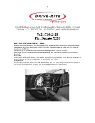
Unit 626 Kilshane Avenue, North West Business Park, Ballycoolin, Dublin 15, Ireland<br />
Telephone: +353 1 8612 632, Fax: +353 1 8612 647, email: sales@driveriteltd.com<br />
www.driveriteltd.com<br />
<strong>RENAULT</strong> <strong>MASTER</strong> <strong>X62</strong> (<strong>FRONT</strong> <strong>WHEEL</strong> <strong>DRIVE</strong>)<br />
<strong>W21</strong>-<strong>760</strong>-<strong>3118</strong><br />
OUTBOARD KIT<br />
PRELIMINARY INSTALLATION INSTRUCTIONS<br />
All work should be carried out in a properly equipped workshop with due regard to Health and Safety<br />
Regulations. No further reference to Health and Safety Regulations will be made, but they must be<br />
considered at all times.<br />
The kit should be opened and the contents checked against the parts list provided.<br />
Identify the various components and familiarise yourself with them using pictures and information<br />
provided.<br />
WARNING<br />
Do not inflate this assembly when it is unrestricted. When installed, a minimum of 0.5 bar should be<br />
maintained in the air springs at all times to avoid damage. Do not inflate beyond 6.5 bar.<br />
Note: The assembly of this kit should be carried out by trained technical personnel. This is<br />
necessary, as auxiliary tools are required for assembly.
Brackets<br />
Parts List<br />
Leaf-spring saddle Bracket x 2 (Handed)<br />
Airspring Bracket x2 (Handed)<br />
Spacer x2<br />
Upper Bracket x2 (Handed)<br />
Cross Member x1<br />
Left Right<br />
Left Right<br />
Left Right<br />
2
Fasteners<br />
Description Quantity<br />
M8 x 25 Countersunk Bolts 8<br />
M10 x 40 Countersunk Bolt 2<br />
M10 Flat Washer 2<br />
M10 Locknuts 2<br />
M8 x 55 Hex Head Bolt 4<br />
M8 Locknuts 8<br />
M8 Flat Washers 16<br />
Cable Ties 10<br />
3/8 x 3/4 Flange Bolt 2<br />
Thermal Sleeves 2<br />
6781 Air Bellows 2<br />
6mm Tubing 5<br />
3/8 x 3/4 Flange Nuts 4<br />
1/4"-6mm Elbow 2<br />
6mm Inflation valve 2<br />
6mm Tee piece 1<br />
IMPORTANT<br />
This kit is not designed to increase the GVW (Gross Vehicle Weight) of your vehicle. For your safety<br />
and to prevent possible damage to your vehicle, do not exceed the maximum load recommended by<br />
the vehicle manufacturer at any time.<br />
3
INSTALLATION PROCEDURE<br />
There 2 different types of bump stop arrangements.<br />
Option 1<br />
Full length bump stop<br />
Option 2<br />
Reduced length bump stock with 60mm spacer<br />
Remove the rubber bump stop by pulling the rubber<br />
bumper away from the metal plate.<br />
This will reveal an M10 bolt. Remove this bolt and the<br />
bump stop bracket.<br />
Remove the 60mm spacer if present.<br />
The remaining hole will be used to fix the upper<br />
bracket to the chassis.<br />
Option 1<br />
Option 2<br />
4
If your vehicle has Option 1 with the full length bump<br />
stop then it is very important that the length of the<br />
M10 threaded bar on the upper brackets is reduced<br />
from 80mm to 20mm as shown.<br />
If the threaded bar is not reduced it will make contact<br />
with the bump stop receiver plate and potentially cause<br />
damage.<br />
If your vehicle has Option 2 do not reduce the length<br />
of the threaded bar.<br />
There is an M8 bolt securing the brake line brackets to<br />
the leaf spring saddle (Circled).<br />
Temporarily remove this bolt.<br />
Option 1<br />
20mm<br />
Option 2<br />
80mm<br />
5
Place the leaf spring saddle bracket on a surface with a<br />
90 degree angle so the face with the red line is resting<br />
flat on the surface as shown.<br />
Bolt the airspring to the airspring bracket using the<br />
3/8” UNC flange head bolt. Do not tighten fully at this<br />
stage.<br />
Insert the head of the bolt through the 25mm hole in<br />
the leafspring saddle bracket and align the countersunk<br />
holes with the corresponding holes in the lower<br />
leafspring bracket. Ensure the countersunk holes are<br />
facing up.<br />
These brackets are handed. Ensure you are installing<br />
the correct bracket on each side (See parts list).<br />
Measure the distance from a fixed 90 degree angle<br />
(Indicated by the broken line) to each of the studs.<br />
Measurement A must be the same as measurement B.<br />
When both measurements match tighten the 3/8” UNC<br />
flange head bolt fully and re-check the measurements.<br />
6
Screw a ¼” elbow into the airspring with the tubing<br />
inlet facing the direction shown.<br />
There are 2 holes on the leaf-spring saddle saddle. The<br />
foreword hole is used to fix the brake line bracket in<br />
place while the rear one should be free. Place the<br />
spacer over the rear hole as shown.<br />
(A)<br />
(B)<br />
7
Place the leaf-spring saddle bracket over the 2 x M8<br />
holes in the saddle bracket. The brake line bracket and<br />
the spacer will be clamped under the saddle bracket.<br />
Ensure the indicated flange is facing inboard.<br />
Remember these brackets are handed so ensure you are<br />
installing the correct bracket on each side.<br />
Bolt in place using the M8 countersunk bolts.<br />
Ensure the brake line bracket is correctly seated.<br />
Repeat on the opposite side again ensuring the brake<br />
line brackets are correctly seated. There is a small<br />
amount of movement in the brake line bracket that will<br />
allow it to be twisted from left to right in order to<br />
ensure the saddle bracket does not interfere with it.<br />
Place the airspring with the lower bracket assembly<br />
over the leaf-spring saddle bracket and bolt in place<br />
using the M8 countersunk bolts, flat washer and nyloc<br />
nut.<br />
Note that each bracket is held in place using 2<br />
countersunk bolts, one of which is indicated in the<br />
picture on the right. Ensure each bracket is secured<br />
using 2 countersunk bolts<br />
8
Place the upper bracket over the airspring as shown<br />
Bolt the upper bracket to the airspring using the 3/8”<br />
UNC flange nuts.<br />
Now is a good time to face the air fitting in the<br />
direction that the airline will be routed because once<br />
the upper bracket is in place access will be restricted.<br />
Bolt the upper bracket to the chassis using the M10<br />
countersunk bolts.<br />
Ensure the upper bracket is resting firmly against the<br />
chassis as shown, there should be no gaps.<br />
9
Replace the bump stop bracket over the M10 threaded<br />
bar and secure in place. The picture on the right shows<br />
the full length bump stop bracket. If your vehicle has<br />
the reduced length bump stop with the 60mm spacer<br />
then you must replace both the 60mm spacer and bump<br />
stop bracket.<br />
Reinsert the rubber bump stop.<br />
Bolt the cross member in place using the M8 hex head<br />
bolts, flat washers and nyloc nuts.<br />
10
Uncoil the air tubing and cut it into two equal lengths.<br />
DO NOT FOLD OR KINK THE TUBING. The air<br />
line tubing should not be bent or curved sharply as it<br />
may buckle with age.<br />
Make the cut as square as possible. Insert one end of<br />
the tubing into the elbow fitting installed in the top of<br />
the air helper spring.<br />
Select a location on the vehicle for the inflation valves.<br />
The locations can be on the bumper or the body of the<br />
vehicle but be sure that it is in a protected location so<br />
the valve will not be damaged yet still be accessible<br />
for the inflation wand. Drill an 8mm hole or use an<br />
existing hole and install the air inflation valve using<br />
two 8mm flat washers per valve as supports. Run the<br />
tubing from the air spring to the inflation valve,<br />
routing it to avoid direct heat from the exhaust, and<br />
away from sharp edges.<br />
Thermal sleeves may be provided for these conditions.<br />
Push the end of the air line tubing into the inflation<br />
valve. Secure the tubing in place with the nylon ties<br />
provided.<br />
Once the inflation valves are installed, inflate the air springs and check the fittings for air leaks with an<br />
applied solution of soap and water. If a leak is detected at a tubing connection then check to make sure<br />
that the tube is cut as square as possible and that it is pushed completely into the fitting. The tubing can<br />
easily be removed from the fittings by pushing the collar towards the body of the fitting and then pulling<br />
out the tube. If a leak is detected where the fitting screws into the spring, screw the elbow into the spring<br />
until the leak stops.<br />
Reinflate the air springs and check for leaks as noted above.<br />
This now completes the installation. Before proceeding, check once again to be sure you have proper<br />
clearance around the airsprings. With a load on the vehicle and the helper air springs inflated, there<br />
must have at least 15mm clearance around the air springs.<br />
For best comfort use only enough air pressure in the air springs to level the vehicle when viewed from<br />
the side (front to rear). This amount will vary depending on the load, location of load, condition of<br />
existing suspension and personal preference.<br />
NOTE: Too much air pressure in the air springs will result in a stiffer suspension, while too little air<br />
pressure will allow the air spring to bottom out over rough conditions. Too little air pressure will also<br />
not provide the improvement in handling that is possible.<br />
TO PREVENT POSSIBLE DAMAGE MAINTAIN A MINIMUM OF 0.5 BAR IN THE AIR<br />
SPRINGS AT ALL TIMES.<br />
11