You also want an ePaper? Increase the reach of your titles
YUMPU automatically turns print PDFs into web optimized ePapers that Google loves.
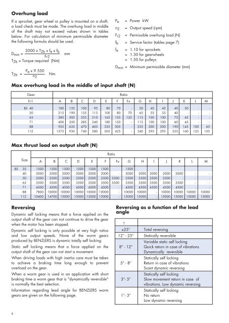
Overhung load<br />
If a sprocket, gear wheel or pulley is mounted on a shaft,<br />
a load check must be made. The overhung load in middle<br />
of the shaft may not exceed values shown in tables<br />
below. For calculation of minimum permissible diameter<br />
the following formula should be used.<br />
D min = 2000 x T 2b x f e x f b<br />
Fr2<br />
T 2b = Torque required (Nm)<br />
T 2b = P e x 9 550<br />
n 2<br />
Nm<br />
mm<br />
P e = Power kW<br />
n 2 = Output speed (rpm)<br />
F r2 = Permissible overhung load (N)<br />
f b = Service factor (tables page 7)<br />
f e<br />
= 1.10 for sprockets<br />
= 1.30 for gearwheels<br />
= 1.50 for pulleys<br />
D min = Minimum permissible diameter (mm)<br />
Max overhung load in the middle of input shaft (N)<br />
Gear<br />
Ratio<br />
Fr1 A B C D E F Fx G H I J K L M<br />
BS 40 180 135 100 95 80 70 - 50 45 45 40 30 - -<br />
50 215 190 155 115 100 80 70 65 55 55 40 - - -<br />
63 385 305 255 210 165 155 125 115 100 100 75 45 - -<br />
71 400 350 285 240 180 150 - 115 100 100 60 45 - -<br />
88 925 635 470 405 335 305 - 235 200 200 190 145 100 65<br />
112 1375 930 740 580 505 425 - 340 295 295 255 160 125 105<br />
Max thrust load on output shaft (N)<br />
Size<br />
Ratio<br />
A B C D E F Fx G H I J K L M<br />
BS 35 1500 1500 1500 1500 1500 1500 1500<br />
40 2000 2000 2000 2000 2000 2000 - 2000 2000 2000 2000 2000 - -<br />
50 2500 2500 2500 2500 2500 2500 2500 2500 2500 2500 2500 - - -<br />
63 3500 3500 3500 3500 3500 3500 3500 3500 3500 3500 3500 3500 - -<br />
71 4500 4500 4500 4500 4500 4500 - 4500 4500 4500 4500 4500 - -<br />
88 7800 10000 10000 10000 10000 10000 - 10000 10000 - 10000 10000 10000 10000<br />
112 10400 14700 15000 15000 15000 15000 - 15000 15000 - 15000 15000 15000 15000<br />
Reversing<br />
Dynamic self locking means that a force applied on the<br />
output shaft of the gear can not continue to drive the gear<br />
when the motor has been stopped.<br />
Dynamic self locking is only possible at very high ratios<br />
and low output speeds. None of the worm gears<br />
produced by BENZLERS is dynamic totally self locking.<br />
Static self locking means that a force applied on the<br />
output shaft of the gear can not start a movement.<br />
When driving loads with high inertia care must be taken<br />
to achieve a braking time long enough to prevent<br />
overload on the gear.<br />
When a worm gear is used in an application with short<br />
braking time a worm gear that is "dynamically reversible"<br />
is normally the best selection.<br />
Information regarding lead angle for BENZLERS worm<br />
gears are given on the following page.<br />
Reversing as a function of the lead<br />
angle<br />
γ<br />
≥25° Total reversing<br />
12° - 25° Statically reversible<br />
Variable static self locking<br />
8° - 12° Quick return in case of vibrations<br />
Dynamically reversible<br />
Statically self locking<br />
5° - 8° Return in case of vibrations<br />
Scant dynamic reversing<br />
Statically self locking<br />
3°- 5° Slow movement return in case of<br />
vibrations. Low dynamic reversing<br />
Statically self locking<br />
1°- 3° No return<br />
Low dynamic reversing<br />
8


