Energy saving in compressed air systems - Norgren Pneumatics ...
Energy saving in compressed air systems - Norgren Pneumatics ...
Energy saving in compressed air systems - Norgren Pneumatics ...

You also want an ePaper? Increase the reach of your titles
YUMPU automatically turns print PDFs into web optimized ePapers that Google loves.
How to improve energy efficiency<br />
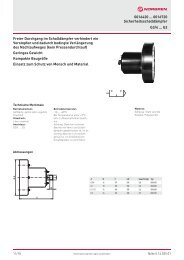
Double act<strong>in</strong>g cyl<strong>in</strong>ders are usually applied to give a power stroke <strong>in</strong> one direction but<br />
simply return the piston rod <strong>in</strong> the other direction. If the control valve is connected to a<br />
s<strong>in</strong>gle supply pressure, the return stroke will be at the same pressure as the power stroke<br />
thereby wast<strong>in</strong>g energy.<br />
Where large bore, long stroke or multiple cyl<strong>in</strong>der <strong>systems</strong> exist, considerable <strong>sav<strong>in</strong>g</strong>s<br />
can be made. Use a pressure regulator to reduce the return stroke pressure. Where<br />
several cyl<strong>in</strong>ders are <strong>in</strong>volved, a s<strong>in</strong>gle pressure regulator could feed a common low<br />
pressure supply to the changeover valves. Use control valves that can be reverse<br />
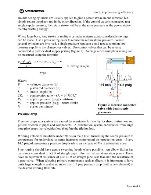
connected to provide dual supply port<strong>in</strong>g (figure 7). Average <strong>air</strong> consumption <strong>sav<strong>in</strong>g</strong> can<br />
be measured us<strong>in</strong>g the formula:<br />
π (D 2 - d 2 ) x L x (CR1 - CR2) x N<br />
4 = <strong>sav<strong>in</strong>g</strong> <strong>in</strong> scfm,<br />
1728<br />
Where:<br />
D = cyl<strong>in</strong>der diameter (<strong>in</strong>)<br />
d = piston rod diameter (<strong>in</strong>)<br />
L = stroke length (<strong>in</strong>)<br />
CRx = compression ratio = (Px + 14.7)/14.7<br />
P1 = applied pressure (psig) - outstroke<br />
P2 = applied pressure (psig) - return stroke<br />
N = cycles per m<strong>in</strong>ute<br />
Pressure drop<br />
Figure 7: Reverse connected<br />
valve with dual supply<br />
pressures<br />
Pressure drops <strong>in</strong> a system are caused by resistance to flow by localized restriction and<br />
general friction <strong>in</strong> pipes and components. A distribution system constructed from large<br />
bore pipe keeps the velocities low therefore the friction low.<br />
Work<strong>in</strong>g velocities should be under 20 ft/s <strong>in</strong> ma<strong>in</strong> l<strong>in</strong>e. Increas<strong>in</strong>g the source pressure to<br />
compensate for undersized <strong>systems</strong> <strong>in</strong>creases <strong>compressed</strong> <strong>air</strong> production costs. Every<br />
14.5 psig of unnecessary pressure drop leads to an <strong>in</strong>crease of 7% <strong>in</strong> generat<strong>in</strong>g costs.<br />
Pipe rout<strong>in</strong>g should have gentle sweep<strong>in</strong>g bends where possible. An elbow fitt<strong>in</strong>g has<br />
resistance equivalent to 5.2 ft of straight pipe. Use ball valves at isolation po<strong>in</strong>ts. These<br />
have an equivalent resistance of just 1.3 ft of straight pipe, less than half the resistance of<br />
a gate valve. When select<strong>in</strong>g primary components such as filters, it is important to have<br />
units large enough to realise no more than 1.5 psig pressure drop (with a new element) at<br />
the desired work<strong>in</strong>g flow rate.<br />
Page 6 of 8