Energy saving in compressed air systems - Norgren Pneumatics ...
Energy saving in compressed air systems - Norgren Pneumatics ...
Energy saving in compressed air systems - Norgren Pneumatics ...

Create successful ePaper yourself
Turn your PDF publications into a flip-book with our unique Google optimized e-Paper software.
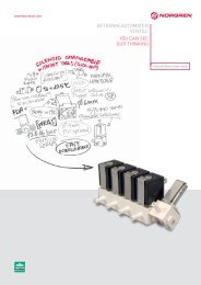
How to improve energy efficiency<br />
<strong>Energy</strong> <strong>sav<strong>in</strong>g</strong> <strong>in</strong> <strong>compressed</strong> <strong>air</strong> <strong>systems</strong> — how <strong>Norgren</strong> is<br />
help<strong>in</strong>g to improve energy efficiency<br />
Compressed <strong>air</strong> is often wrongly assumed to be cheap or even a ’free’ source of power. A<br />
typical 1000 scfm <strong>in</strong>stallation will consume $32,000 of electricity a year. Dur<strong>in</strong>g its<br />
lifetime, energy costs represent 75% of the total cost of buy<strong>in</strong>g and runn<strong>in</strong>g a compressor.<br />
Consider then an <strong>in</strong>efficient system and the costs <strong>in</strong>volved beg<strong>in</strong> to rise rapidly.<br />
Numerous <strong>in</strong>dependent studies confirm that <strong>in</strong>dustry wastes around 30% of the<br />
<strong>compressed</strong> <strong>air</strong> it generates, equivalent to wast<strong>in</strong>g $9,600 <strong>in</strong> a typical 1000 scfm<br />
<strong>in</strong>stallation.<br />
Fuelled by the need for pollution control and <strong>in</strong>creas<strong>in</strong>g difficulty <strong>in</strong> extract<strong>in</strong>g raw<br />
materials, energy <strong>sav<strong>in</strong>g</strong> and the efficient use of energy is one of the most important<br />
issues fac<strong>in</strong>g <strong>in</strong>dustry worldwide.<br />
<strong>Norgren</strong>, world leader <strong>in</strong> pneumatic components and automation <strong>systems</strong>, has taken the<br />
<strong>in</strong>itiative to help <strong>compressed</strong> <strong>air</strong> users to <strong>in</strong>crease energy efficiency. By systematic selfexam<strong>in</strong>ation<br />
and with the help of safety and energy <strong>sav<strong>in</strong>g</strong> techniques and products, there<br />
is the potential for large and small users to make substantial annual cost <strong>sav<strong>in</strong>g</strong>s which<br />
directly <strong>in</strong>crease overall profits, as well as mak<strong>in</strong>g a valuable contribution to the wider<br />
issues.<br />
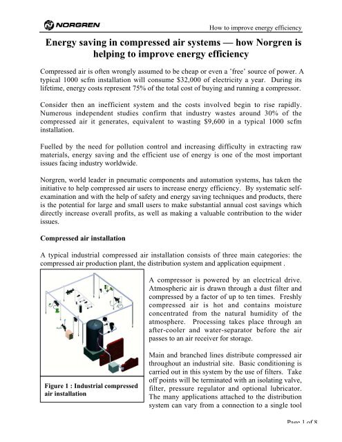
Compressed <strong>air</strong> <strong>in</strong>stallation<br />
A typical <strong>in</strong>dustrial <strong>compressed</strong> <strong>air</strong> <strong>in</strong>stallation consists of three ma<strong>in</strong> categories: the<br />
<strong>compressed</strong> <strong>air</strong> production plant, the distribution system and application equipment .<br />
Figure 1 : Industrial <strong>compressed</strong><br />
<strong>air</strong> <strong>in</strong>stallation<br />
A compressor is powered by an electrical drive.<br />
Atmospheric <strong>air</strong> is drawn through a dust filter and<br />
<strong>compressed</strong> by a factor of up to ten times. Freshly<br />
<strong>compressed</strong> <strong>air</strong> is hot and conta<strong>in</strong>s moisture<br />
concentrated from the natural humidity of the<br />
atmosphere. Process<strong>in</strong>g takes place through an<br />
after-cooler and water-separator before the <strong>air</strong><br />
passes to an <strong>air</strong> receiver for storage.<br />
Ma<strong>in</strong> and branched l<strong>in</strong>es distribute <strong>compressed</strong> <strong>air</strong><br />
throughout an <strong>in</strong>dustrial site. Basic condition<strong>in</strong>g is<br />
carried out <strong>in</strong> this system by the use of filters. Take<br />
off po<strong>in</strong>ts will be term<strong>in</strong>ated with an isolat<strong>in</strong>g valve,<br />
filter, pressure regulator and optional lubricator.<br />
The many applications attached to the distribution<br />
system can vary from a connection to a s<strong>in</strong>gle tool<br />
Page 1 of 8
to sophisticated and extensive special purpose mach<strong>in</strong>es and <strong>systems</strong>.<br />
How to improve energy efficiency<br />
The ma<strong>in</strong> causes of wasted energy are leaks, pressure drops, over pressurization, misuse<br />
of jets and poor compressor management.<br />
An example factory has an <strong>in</strong>stalled compressor capacity of 1,500 cfm, and average<br />
demand of 1000 cfm. It operates 24 hours per day, 7 days per week, for 50 weeks a year.<br />
Electricity costs 0.068 $/kWh (national US average 99). The compressor duty cycle is<br />
75%. To evaluate the power needed: 4.5 cfm compressor capacity require 1 compressor<br />
horsepower. The total runn<strong>in</strong>g cost is then $107,000 per year.<br />
If the <strong>compressed</strong> <strong>air</strong> system has many of the commonly found problems, it is likely that<br />
around 30% of the <strong>air</strong> produced is wasted. Cur<strong>in</strong>g the problems will yield a fast payback<br />
and substantial <strong>sav<strong>in</strong>g</strong>s of $ 32,100 <strong>in</strong> the first year.<br />
Leakage<br />
Because <strong>compressed</strong> <strong>air</strong> leaks do not make a mess like oil leaks, it is easy to ignore them.<br />
The cont<strong>in</strong>uous hiss of leaks is usually dismissed as part of the general background and is<br />
often drowned by the higher noise levels from mach<strong>in</strong>ery. Generation capacity is<br />
frequently <strong>in</strong>creased needlessly, when simply fix<strong>in</strong>g the leaks would have restored system<br />
efficiency.<br />
At a considerable high price it is well worth establish<strong>in</strong>g a planned ma<strong>in</strong>tenance rout<strong>in</strong>e<br />
that is <strong>in</strong>tolerant of leaks. Leakage is the major source of energy loss <strong>in</strong> <strong>compressed</strong> <strong>air</strong><br />
<strong>systems</strong>. A typical plant may lose up to 30% of its <strong>compressed</strong> <strong>air</strong> through poorly<br />
ma<strong>in</strong>ta<strong>in</strong>ed pipe jo<strong>in</strong>ts, fitt<strong>in</strong>gs, coupl<strong>in</strong>gs and equipment.<br />
Where to f<strong>in</strong>d leaks<br />
Ag<strong>in</strong>g pipework particularly at corroded jo<strong>in</strong>ts and take off po<strong>in</strong>ts.<br />
Flange connectors where gaskets and pipe dope need replac<strong>in</strong>g.<br />
Fitt<strong>in</strong>gs that have worked loose or have had excessive stra<strong>in</strong> placed on them.<br />
Manifolds with closely spaced connections. These can be easy to ignore when a leak<strong>in</strong>g<br />
fitt<strong>in</strong>g is difficult to access.<br />
Flexible hoses with cuts and splits caused by stra<strong>in</strong> and abrasion.<br />
Coupl<strong>in</strong>gs with damaged seals. Grit may have been picked up dur<strong>in</strong>g the break and<br />
make process.<br />
Dra<strong>in</strong> valves found on <strong>air</strong> receivers, drip leg dra<strong>in</strong>s, filters and other equipment can<br />
become stuck open due to pipe scale and sludge or even <strong>in</strong>tentionally left partially open<br />
to avoid the ma<strong>in</strong>tenance rout<strong>in</strong>e.<br />
Pneumatic components <strong>in</strong>clud<strong>in</strong>g tools, valves and actuators are all subject to worn and<br />
damaged seals result<strong>in</strong>g <strong>in</strong> leaks.<br />
Page 2 of 8
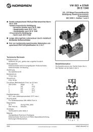
Isolate <strong>systems</strong> when not <strong>in</strong> use<br />
How to improve energy efficiency<br />
Where a subsystem has unavoidable leaks or a natural idle consumption, it can be<br />
isolated from the <strong>air</strong> supply until it is required <strong>in</strong> service aga<strong>in</strong>. Simple shut-off valves<br />
(figure 2), or electrically operated soft start dump valves (figure 3) offer cost effective<br />
ways to isolate leaky <strong>systems</strong> that are used <strong>in</strong>termittently.<br />
Figure 2: Manual shutoff<br />
valve<br />
Estimat<strong>in</strong>g the leakage<br />
For a particular <strong>in</strong>stallation get a feel for the percentage of <strong>air</strong> lost to leaks. Tests need to<br />
be conducted at night or other time when manufactur<strong>in</strong>g is closed. Allow the compressor<br />
to fill the system to normal work<strong>in</strong>g pressure, then record the tim<strong>in</strong>g of the load/off-load<br />
cycle of the compressor as it does noth<strong>in</strong>g more than susta<strong>in</strong> the leaks.<br />
Figure 4: A<br />
portable<br />
plug-<strong>in</strong> flow<br />
meter<br />
Figure 3: Soft start dump valve<br />
provides isolation and aded safety<br />
Compare this with the normal daily compressor cycle to estimate the<br />
losses. The actual losses are likely to be more. Devices and<br />
components used <strong>in</strong> mach<strong>in</strong>ery may well have dynamic leakage<br />
occurr<strong>in</strong>g dur<strong>in</strong>g their normal cycle of use but no leak when not<br />
runn<strong>in</strong>g.<br />
Identify leaks by listen<strong>in</strong>g for a characteristic hiss. Exam<strong>in</strong>e suspect<br />
areas and if necessary spray on a leak detection liquid and watch for<br />
bubbles. Static leak rates to <strong>in</strong>dividual mach<strong>in</strong>es and local sections can<br />
be measured us<strong>in</strong>g a plug <strong>in</strong> flow meter.<br />
Please note: audio leak detection equipment is available for plant-wide<br />
audits of large leaks even while production is operat<strong>in</strong>g.<br />
Page 3 of 8
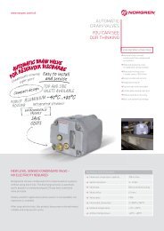
Flow to<br />
atmosphere<br />
[scfm]<br />
@ P1=100<br />
psig<br />
How to improve energy efficiency<br />
Orifice flow data<br />
can be used to<br />
approximate the<br />
flow to<br />
atmosphere<br />
through holes of<br />
different sizes.<br />
The graph (figure<br />
5) shows the<br />
relation between<br />
flow and hole<br />
diameter.<br />
The basis for calculat<strong>in</strong>g the costs of flow losses is the waste formula:<br />
Total cost = 0.19 x operat<strong>in</strong>g hours per year x flow scfm x energy cost per kWh. (0.19 is<br />
a factor relat<strong>in</strong>g kW to scfm for typical compressors).<br />
The cost of a s<strong>in</strong>gle cont<strong>in</strong>uous leak from a 0.08 <strong>in</strong> (2mm) diameter orifice with 8 scfm<br />
is:<br />
0.19 x 8400 x 8 x 0.068 = $ 868 / year<br />
The average leak will take around half a man-hour to fix and offer quick payback.<br />
Misuse of jets<br />
35<br />
30<br />
25<br />
20<br />
15<br />
10<br />
5<br />
0<br />
Flow [scfm]<br />
Diameter [<strong>in</strong>] of round orifice<br />
Figure 5: Leakage rate for different hole diameters<br />
A major waste of <strong>compressed</strong> <strong>air</strong> is lack of consideration for the detailed specification<br />
and application of equipment. Frequently with<strong>in</strong> a mach<strong>in</strong>e cycle, jets of <strong>air</strong> from nozzles<br />
are used to carry out processes such as dust<strong>in</strong>g, cool<strong>in</strong>g, separat<strong>in</strong>g and other tasks.<br />
Sometimes due to the normal high throughput of a mach<strong>in</strong>e these jets are left<br />
permanently runn<strong>in</strong>g. With most mach<strong>in</strong>es there will be times when the production<br />
process is <strong>in</strong>termittent or even at a halt. Jets that cont<strong>in</strong>ue to run <strong>in</strong> these circumstances<br />
are <strong>in</strong>curr<strong>in</strong>g unnecessary costs. With a suitable valve and sensor, these can be controlled<br />
automatically so they are only on when required.<br />
When apply<strong>in</strong>g jets ensure that the distance between the exit nozzle and the product is as<br />
short as possible, this will allow the supply pressure to be reduced. Air saver nozzles are<br />
designed to entra<strong>in</strong> and accelerate <strong>air</strong>, these produce the desired outputs with reduced<br />
supply pressures (typically 30 psig). Sav<strong>in</strong>gs of up to twenty times can result.<br />
Page 4 of 8
Figure 6: Safety blow gun<br />
with <strong>air</strong> saver nozzle<br />
Over pressurisation<br />
How to improve energy efficiency<br />
Safety issues of hand held blowguns are of extreme<br />
importance. Select<strong>in</strong>g pressure regulation and<br />
blowgun types of the <strong>air</strong> saver and safety design,<br />
good practice can be adopted to reduce the risk of<br />
<strong>in</strong>jury as well as <strong>sav<strong>in</strong>g</strong> costs (figure 6).<br />
Many <strong>systems</strong> run at full l<strong>in</strong>e pressure with the only control be<strong>in</strong>g the compressor cut off<br />
switch. Pneumatic <strong>systems</strong> and <strong>in</strong>dividual components have an optimum operat<strong>in</strong>g<br />
pressure and flow for their particular application. Both under and over pressurisation will<br />
slow down production rates and over pressurisation additionally <strong>in</strong>creases the amount of<br />
<strong>air</strong> consumed and wear <strong>in</strong> components.<br />
The absence of pressure regulators <strong>in</strong> a system may <strong>in</strong>dicate that equipment is be<strong>in</strong>g used<br />
at excessive pressures. Sav<strong>in</strong>gs can be realised <strong>in</strong> many areas, <strong>in</strong>clud<strong>in</strong>g <strong>air</strong> tools, control<br />
valves and on the return stroke of large double act<strong>in</strong>g cyl<strong>in</strong>ders. Check for correct<br />
lubrication, high friction will demand higher set pressures.<br />
For a device or system that is over pressurised, the cost can be calculated by us<strong>in</strong>g a<br />
simple calculation. For example, a system is designed to run at 45 psig and consume <strong>air</strong><br />
at 17 cfm. If it is supplied at 100 psig, the waste of <strong>air</strong> <strong>in</strong> scfm can be found us<strong>in</strong>g the<br />
follow<strong>in</strong>g approach:<br />
Compression Ratio<br />
CR1 = (14.7 + P1) / 14.7 = (14.7+45) / 14.7 = 4.06<br />
CR2 = (14.7 + P2) / 14.7 = (14.7+100) / 14.7 = 7.8<br />
To convert cfm <strong>in</strong>to scfm:<br />
Air usage at normal pressure = CR1 x <strong>air</strong> consumption = 4.06 x 17 = 69 scfm<br />
Air usage at high pressure = CR2 x <strong>air</strong> consumption = 7.8 x 17 = 132.6 scfm<br />
This represents a wastage of <strong>compressed</strong> <strong>air</strong> of 63.6 scfm. Us<strong>in</strong>g the formula from the previous<br />
page and the same operation time this wastage represents $ 6900 / year.<br />
Page 5 of 8
How to improve energy efficiency<br />
Double act<strong>in</strong>g cyl<strong>in</strong>ders are usually applied to give a power stroke <strong>in</strong> one direction but<br />
simply return the piston rod <strong>in</strong> the other direction. If the control valve is connected to a<br />
s<strong>in</strong>gle supply pressure, the return stroke will be at the same pressure as the power stroke<br />
thereby wast<strong>in</strong>g energy.<br />
Where large bore, long stroke or multiple cyl<strong>in</strong>der <strong>systems</strong> exist, considerable <strong>sav<strong>in</strong>g</strong>s<br />
can be made. Use a pressure regulator to reduce the return stroke pressure. Where<br />
several cyl<strong>in</strong>ders are <strong>in</strong>volved, a s<strong>in</strong>gle pressure regulator could feed a common low<br />
pressure supply to the changeover valves. Use control valves that can be reverse<br />
connected to provide dual supply port<strong>in</strong>g (figure 7). Average <strong>air</strong> consumption <strong>sav<strong>in</strong>g</strong> can<br />
be measured us<strong>in</strong>g the formula:<br />
π (D 2 - d 2 ) x L x (CR1 - CR2) x N<br />
4 = <strong>sav<strong>in</strong>g</strong> <strong>in</strong> scfm,<br />
1728<br />
Where:<br />
D = cyl<strong>in</strong>der diameter (<strong>in</strong>)<br />
d = piston rod diameter (<strong>in</strong>)<br />
L = stroke length (<strong>in</strong>)<br />
CRx = compression ratio = (Px + 14.7)/14.7<br />
P1 = applied pressure (psig) - outstroke<br />
P2 = applied pressure (psig) - return stroke<br />
N = cycles per m<strong>in</strong>ute<br />
Pressure drop<br />
Figure 7: Reverse connected<br />
valve with dual supply<br />
pressures<br />
Pressure drops <strong>in</strong> a system are caused by resistance to flow by localized restriction and<br />
general friction <strong>in</strong> pipes and components. A distribution system constructed from large<br />
bore pipe keeps the velocities low therefore the friction low.<br />
Work<strong>in</strong>g velocities should be under 20 ft/s <strong>in</strong> ma<strong>in</strong> l<strong>in</strong>e. Increas<strong>in</strong>g the source pressure to<br />
compensate for undersized <strong>systems</strong> <strong>in</strong>creases <strong>compressed</strong> <strong>air</strong> production costs. Every<br />
14.5 psig of unnecessary pressure drop leads to an <strong>in</strong>crease of 7% <strong>in</strong> generat<strong>in</strong>g costs.<br />
Pipe rout<strong>in</strong>g should have gentle sweep<strong>in</strong>g bends where possible. An elbow fitt<strong>in</strong>g has<br />
resistance equivalent to 5.2 ft of straight pipe. Use ball valves at isolation po<strong>in</strong>ts. These<br />
have an equivalent resistance of just 1.3 ft of straight pipe, less than half the resistance of<br />
a gate valve. When select<strong>in</strong>g primary components such as filters, it is important to have<br />
units large enough to realise no more than 1.5 psig pressure drop (with a new element) at<br />
the desired work<strong>in</strong>g flow rate.<br />
Page 6 of 8
Never match a filter s maximum flow rate to<br />
the desired flow rate. Fitt<strong>in</strong>g a smaller filter is<br />
false economy. Due to the smaller surface area<br />
of the element (figure 8) it will give a higher<br />
<strong>in</strong>itial pressure drop and contam<strong>in</strong>ate more<br />
quickly.<br />
Filtration<br />
How to improve energy efficiency<br />
Figure 8: False economy of<br />
overflow<strong>in</strong>g a smaller filter<br />
Filtration <strong>in</strong> various parts of a system is essential for the removal of water and solid<br />
particles. This ensures long life and trouble free operation of components <strong>in</strong> <strong>compressed</strong><br />
<strong>air</strong> <strong>systems</strong>. The micrometer size of the filter elements determ<strong>in</strong>es the <strong>air</strong> quality.<br />
The standard size for the vast majority of applications is 40 µm. F<strong>in</strong>er sizes of 5 µm and<br />
0.01 µm are available for special applications but size for size will be more restrictive<br />
(figure 9). F<strong>in</strong>e grade filters should be <strong>in</strong>stalled based on their specific applications. Do<br />
not filter the whole of a sub-system to a f<strong>in</strong>e grade if the majority of connections to it<br />
need only standard grade.<br />
Figure 9: The effect of filter grade on pressure<br />
drop<br />
Page 7 of 8
How to improve energy efficiency<br />
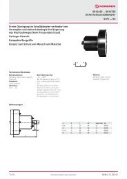
Filters can be specified with pressure drop <strong>in</strong>dicators, also known as ∆ p <strong>in</strong>dicators or<br />
service life <strong>in</strong>dicators, which can be pneumatic or electrical, as standard (figure 10).<br />
These give a visual or remote <strong>in</strong>dication of<br />
when a filter element is becom<strong>in</strong>g too<br />
restrictive and needs replac<strong>in</strong>g. Chang<strong>in</strong>g<br />
the elements at this po<strong>in</strong>t means significant<br />
energy <strong>sav<strong>in</strong>g</strong> (figure 11).<br />
Figure 10: Filters fitted with electrical<br />
and mechanical service <strong>in</strong>dicators<br />
Compressor management<br />
Large compressor <strong>in</strong>stallations are likely to be fitted with sophisticated power and load<br />
management <strong>systems</strong> as part of the package. Simpler compressor <strong>in</strong>stallations with<br />
<strong>in</strong>termittent use could also benefit from automatic compressor management <strong>systems</strong>.<br />
These use figures of expected consumption rate, storage volume and pressure to tell the<br />
compressor how long to run <strong>in</strong> an off load condition before shutt<strong>in</strong>g down dur<strong>in</strong>g times of<br />
low or no demand.<br />
A safety conscious system helps to save energy<br />
Figure 11: Cost <strong>sav<strong>in</strong>g</strong> through<br />
regular element changes<br />
Much of the legislation, standards and codes of practice necessary to ensure safe <strong>systems</strong><br />
deal with correct selection, <strong>in</strong>stallation and ma<strong>in</strong>tenance of equipment and <strong>systems</strong>. This<br />
<strong>in</strong>cludes safety details such as the use of <strong>air</strong> fuses and replacement of old polycarbonate<br />
bowls with new ones or with metal bowls.<br />
Compliance with safety requirements and advice <strong>in</strong>herently addresses many of the issues<br />
appropriate to energy efficient <strong>systems</strong>. Add specific energy <strong>sav<strong>in</strong>g</strong> awareness and a few<br />
fast pay back techniques and pneumatic <strong>systems</strong> of all sizes can realize significantly<br />
reduced operational costs and <strong>in</strong>creased reliability for years to come.<br />
-ends-<br />
Page 8 of 8