Localized induction heating solder bonding for wafer level MEMS ...
Localized induction heating solder bonding for wafer level MEMS ...
Localized induction heating solder bonding for wafer level MEMS ...

Create successful ePaper yourself
Turn your PDF publications into a flip-book with our unique Google optimized e-Paper software.
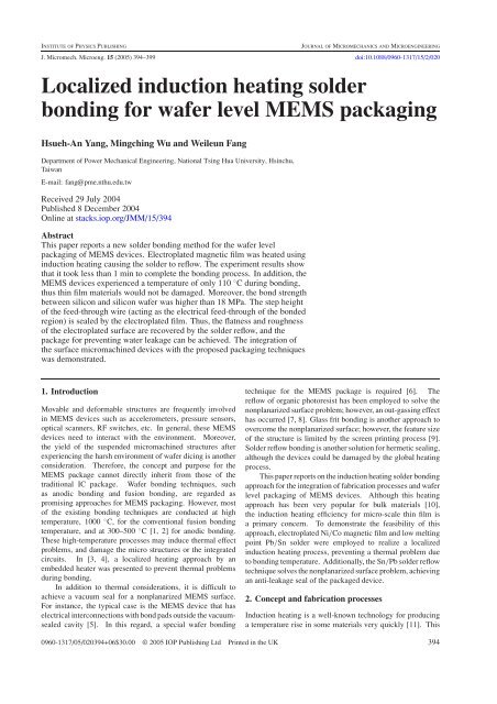
INSTITUTE OF PHYSICS PUBLISHING<br />
JOURNAL OF MICROMECHANICS AND MICROENGINEERING<br />
J. Micromech. Microeng. 15 (2005) 394–399 doi:10.1088/0960-1317/15/2/020<br />
<strong>Localized</strong> <strong>induction</strong> <strong>heating</strong> <strong>solder</strong><br />
<strong>bonding</strong> <strong>for</strong> <strong>wafer</strong> <strong>level</strong> <strong>MEMS</strong> packaging<br />
Hsueh-An Yang, Mingching Wu and Weileun Fang<br />
Department of Power Mechanical Engineering, National Tsing Hua University, Hsinchu,<br />
Taiwan<br />
E-mail: fang@pme.nthu.edu.tw<br />
Received 29 July 2004<br />
Published 8 December 2004<br />
Online at stacks.iop.org/JMM/15/394<br />
Abstract<br />
This paper reports a new <strong>solder</strong> <strong>bonding</strong> method <strong>for</strong> the <strong>wafer</strong> <strong>level</strong><br />
packaging of <strong>MEMS</strong> devices. Electroplated magnetic film was heated using<br />
<strong>induction</strong> <strong>heating</strong> causing the <strong>solder</strong> to reflow. The experiment results show<br />
that it took less than 1 min to complete the <strong>bonding</strong> process. In addition, the<br />
<strong>MEMS</strong> devices experienced a temperature of only 110 ◦ C during <strong>bonding</strong>,<br />
thus thin film materials would not be damaged. Moreover, the bond strength<br />
between silicon and silicon <strong>wafer</strong> was higher than 18 MPa. The step height<br />
of the feed-through wire (acting as the electrical feed-through of the bonded<br />
region) is sealed by the electroplated film. Thus, the flatness and roughness<br />
of the electroplated surface are recovered by the <strong>solder</strong> reflow, and the<br />
package <strong>for</strong> preventing water leakage can be achieved. The integration of<br />
the surface micromachined devices with the proposed packaging techniques<br />
was demonstrated.<br />
1. Introduction<br />
Movable and de<strong>for</strong>mable structures are frequently involved<br />
in <strong>MEMS</strong> devices such as accelerometers, pressure sensors,<br />
optical scanners, RF switches, etc. In general, these <strong>MEMS</strong><br />
devices need to interact with the environment. Moreover,<br />
the yield of the suspended micromachined structures after<br />
experiencing the harsh environment of <strong>wafer</strong> dicing is another<br />
consideration. There<strong>for</strong>e, the concept and purpose <strong>for</strong> the<br />
<strong>MEMS</strong> package cannot directly inherit from those of the<br />
traditional IC package. Wafer <strong>bonding</strong> techniques, such<br />
as anodic <strong>bonding</strong> and fusion <strong>bonding</strong>, are regarded as<br />
promising approaches <strong>for</strong> <strong>MEMS</strong> packaging. However, most<br />
of the existing <strong>bonding</strong> techniques are conducted at high<br />
temperature, 1000 ◦ C, <strong>for</strong> the conventional fusion <strong>bonding</strong><br />
temperature, and at 300–500 ◦ C [1, 2] <strong>for</strong> anodic <strong>bonding</strong>.<br />
These high-temperature processes may induce thermal effect<br />
problems, and damage the micro structures or the integrated<br />
circuits. In [3, 4], a localized <strong>heating</strong> approach by an<br />
embedded heater was presented to prevent thermal problems<br />
during <strong>bonding</strong>.<br />
In addition to thermal considerations, it is difficult to<br />
achieve a vacuum seal <strong>for</strong> a nonplanarized <strong>MEMS</strong> surface.<br />
For instance, the typical case is the <strong>MEMS</strong> device that has<br />
electrical interconnections with bond pads outside the vacuumsealed<br />
cavity [5]. In this regard, a special <strong>wafer</strong> <strong>bonding</strong><br />
technique <strong>for</strong> the <strong>MEMS</strong> package is required [6]. The<br />
reflow of organic photoresist has been employed to solve the<br />
nonplanarized surface problem; however, an out-gassing effect<br />
has occurred [7, 8]. Glass frit <strong>bonding</strong> is another approach to<br />
overcome the nonplanarized surface; however, the feature size<br />
of the structure is limited by the screen printing process [9].<br />
Solder reflow <strong>bonding</strong> is another solution <strong>for</strong> hermetic sealing,<br />
although the devices could be damaged by the global <strong>heating</strong><br />
process.<br />
This paper reports on the <strong>induction</strong> <strong>heating</strong> <strong>solder</strong> <strong>bonding</strong><br />
approach <strong>for</strong> the integration of fabrication processes and <strong>wafer</strong><br />
<strong>level</strong> packaging of <strong>MEMS</strong> devices. Although this <strong>heating</strong><br />
approach has been very popular <strong>for</strong> bulk materials [10],<br />
the <strong>induction</strong> <strong>heating</strong> efficiency <strong>for</strong> micro-scale thin film is<br />
a primary concern. To demonstrate the feasibility of this<br />
approach, electroplated Ni/Co magnetic film and low melting<br />
point Pb/Sn <strong>solder</strong> were employed to realize a localized<br />
<strong>induction</strong> <strong>heating</strong> process, preventing a thermal problem due<br />
to <strong>bonding</strong> temperature. Additionally, the Sn/Pb <strong>solder</strong> reflow<br />
technique solves the nonplanarized surface problem, achieving<br />
an anti-leakage seal of the packaged device.<br />
2. Concept and fabrication processes<br />
Induction <strong>heating</strong> is a well-known technology <strong>for</strong> producing<br />
a temperature rise in some materials very quickly [11]. This<br />
0960-1317/05/020394+06$30.00 © 2005 IOP Publishing Ltd Printed in the UK 394
<strong>Localized</strong> <strong>induction</strong> <strong>heating</strong> <strong>solder</strong> <strong>bonding</strong> <strong>for</strong> <strong>wafer</strong> <strong>level</strong> <strong>MEMS</strong> packaging<br />
(a)<br />
(b)<br />
(c)<br />
Figure 1. The schematic illustration <strong>for</strong> <strong>induction</strong> <strong>heating</strong>. The<br />
sample was placed inside a magnetic field provided by the coil<br />
underneath.<br />
technology has been extensively employed to heat electrically<br />
conductive materials in applications such as melting, <strong>solder</strong>ing<br />
and hardening of metals. As shown in figure 1, the <strong>induction</strong><br />
<strong>heating</strong> system consists of a high-frequency power supply, an<br />
<strong>induction</strong> coil and the work pieces. An ac power supply drives<br />
the <strong>induction</strong> coil, generating a magnetic field. Meanwhile,<br />
an eddy current is developed in the work piece as it is placed<br />
inside the magnetic field. This causes heat to be generated by<br />
the work piece due to the eddy current loss and hysteresis<br />
loss [12]. According to the characteristics of the <strong>heating</strong><br />
mechanism, the work piece can be noncontact and locally<br />
heated in some particular regions. For instance, the composite<br />
work piece in figure 1 consists of silicon, glass and metal parts.<br />
Using <strong>induction</strong> <strong>heating</strong> technology, a higher temperature will<br />
be generated at the metal parts, especially in the ferromagnetic<br />
Ni/Co alloy. These ferromagnetic materials can be exploited<br />
as a localized <strong>heating</strong> element <strong>for</strong> the composite work piece.<br />
Wafer <strong>level</strong> packaging can be realized if the whole <strong>wafer</strong> can<br />
be placed inside the magnetic field in figure 1.<br />
This study has established the fabrication process required<br />
to conduct the presented <strong>bonding</strong> technique <strong>for</strong> silicon<br />
substrates. In addition, fabrication processes used to<br />
encapsulate the MUMPs devices by Si and glass covers by<br />
the presented <strong>bonding</strong> method have also been accomplished.<br />
2.1. Si–Si <strong>bonding</strong> processes<br />
A 4-inch single-side polished silicon <strong>wafer</strong> was deposited<br />
with 200 Å Cr as the adhesive layer and 200 ÅCuasthe<br />
seed layer, as shown in figure 2(a). A Ni/Co alloy was<br />
electroplated on top of the seed layer to act as the spacer.<br />
The solutions <strong>for</strong> the electroplating of the Ni/Co are listed in<br />
table 1; in addition, the deposition rate was 0.1–0.2 µmmin −1<br />
and the current density was 1–5 ASD (ampere/dm 2 ). Since<br />
the Ni/Co alloy is a ferromagnetic material, it has a very<br />
large permeability [11]. Thus, a much higher temperature<br />
was generated by the Ni/Co spacer <strong>for</strong> a given driving current<br />
during the <strong>induction</strong> <strong>heating</strong>. The Sn/Pb alloy <strong>solder</strong> was<br />
electroplated on top of the spacer, as shown in figure 2(b). The<br />
electroplating solutions of the <strong>solder</strong> are listed in table 1; the<br />
deposition rate and the current density were 0.1–0.5 µmmin −1<br />
and 1–4 ASD, respectively. The composition of the Sn/Pb<br />
<strong>solder</strong> was Sn–Pb (63/37), and its melting point was 183 ◦ C.<br />
Figure 2. The concept and fabrication process <strong>for</strong> the present study.<br />
Table 1. The plating solution <strong>for</strong> the electroplating of (a) Ni/Co and<br />
(b) Pb/Sn <strong>solder</strong>.<br />
(a) Electroplating of Ni/Co<br />
Nickel sulfamate Ni(NH 2 SO 4 ) 2·4H 2 O<br />
Cobalt sulfamate Co(NH 2 SO 4 ) 2<br />
Nickel chloride NiCl 2·6H 2 O<br />
Boric acid H 3 BO 3<br />
Stress reducer<br />
450–550 ml l −1<br />
15–25 ml l −1<br />
2–7 g l −1<br />
30–50 g l −1<br />
2–10 ml l −1<br />
(b) Electroplating of Pb/Sn <strong>solder</strong><br />
Tin<br />
12–18 g l −1<br />
Lead<br />
1.5–2.5 g l −1<br />
pH value 3.0–5.0<br />
Specific weight 1.1–1.2<br />
The spacer and <strong>solder</strong> provided more than 50 µm of space<br />
to allow <strong>for</strong> a large range of motion of the <strong>MEMS</strong> devices.<br />
As shown in figure 1, the <strong>induction</strong> coil, driven with<br />
high-frequency ac current, provided the <strong>wafer</strong>s with a<br />
magnetic field. After the two silicon <strong>wafer</strong>s were aligned,<br />
the magnetic field was employed to heat the thin film Ni/Co<br />
magnetic spacer, as illustrated in figure 2(c). In this study,<br />
the process was per<strong>for</strong>med at atmospheric pressure (1 atm).<br />
The <strong>induction</strong> <strong>heating</strong> temperature is significantly influenced<br />
by the magnetic field, the material property (permeability) and<br />
the area of the magnetic layer [11]. Hence, a large area Ni/Co<br />
alloy and a higher driving frequency were required <strong>for</strong> microscale<br />
<strong>induction</strong> <strong>heating</strong>. The driving frequency and current<br />
of the magnetic coil were 100 kHz and 25 A, respectively.<br />
Moreover, the width of the electroplated Ni/Co <strong>bonding</strong> ring<br />
is about 600 µm. It took only 15 s <strong>for</strong> the magnetic spacer<br />
to reach 200 ◦ C using <strong>induction</strong> <strong>heating</strong>, at which point the<br />
<strong>solder</strong> on top of the spacer began to reflow. Thus, the two<br />
silicon <strong>wafer</strong>s were bonded together through the <strong>solder</strong>.<br />
The SEM photograph in figure 3(a) shows the typical<br />
result of silicon substrates after <strong>bonding</strong>. The sample was<br />
purposely broken so that the space provided by the spacer<br />
395
H-A Yang et al<br />
(a)<br />
(a)<br />
(b)<br />
(b)<br />
Figure 3. The SEM photographs of (a) the silicon substrates after<br />
<strong>bonding</strong>, and (b) the close-up of the bonded specimen in the dashed<br />
box region.<br />
(a)<br />
(b)<br />
(c)<br />
(c)<br />
(d)<br />
(e)<br />
Figure 5. The SEM photographs of the integration of surface<br />
micromachined devices and the spacer (a) a4× 4 mirror array<br />
inside the 50 µm height Ni/Co spacer, (b) conducting wires and<br />
<strong>bonding</strong> pads of mirrors and (c) the microscopic section of the<br />
<strong>bonding</strong> region.<br />
2.2. Integration of MUMPs and <strong>bonding</strong> processes<br />
Figure 4. Fabrication process to integrate the surface<br />
micromachined devices with the present <strong>bonding</strong> method.<br />
and <strong>solder</strong> could be clearly observed. The close-up SEM<br />
photograph in figure 3(b) shows a typical cross section of the<br />
bonded silicon–silicon test sample as indicated by the dashed<br />
box in figure 3(a). There are three different layers, including<br />
two Ni/Co spacer layers and one Sn/Pb <strong>solder</strong> layer, between<br />
the silicon substrates. According to the characteristics of<br />
<strong>solder</strong> reflow, no interface was observed in the bonded Sn/Pb<br />
layers.<br />
It is easy to integrate the presented localized <strong>bonding</strong> technique<br />
with other fabrication processes. Moreover, it is possible to<br />
employ this technique to bond silicon and glass. This study<br />
established a process, depicted in figure 4, to demonstrate<br />
the feasibility of integration of 1-poly surface micromachined<br />
structures with the presented packaging techniques. As<br />
shown in figure 4(a), the fabrication started with a 2-poly<br />
surface micromachined process. The first poly-silicon (poly0)<br />
acted as the conducting/grounding layer and the second polysilicon<br />
(poly1) acted as the structural layer. As illustrated<br />
in figure 4(b), the Cr and Cu films were then evaporated and<br />
patterned to per<strong>for</strong>m as the electroplating adhesive layer and<br />
the seed layer, respectively. It was necessary to properly<br />
396
<strong>Localized</strong> <strong>induction</strong> <strong>heating</strong> <strong>solder</strong> <strong>bonding</strong> <strong>for</strong> <strong>wafer</strong> <strong>level</strong> <strong>MEMS</strong> packaging<br />
Figure 6. The experiment set-up in this study <strong>for</strong> <strong>induction</strong> <strong>heating</strong>.<br />
The sample was placed on top of a magnetic coil. The temperature<br />
distribution of the sample was inspected by an infrared microscope.<br />
cover the conducting wire <strong>for</strong>med by the poly0 layer using the<br />
Cr/Cu films. As shown in figure 4(c), a thick photoresist was<br />
spun on and patterned using photolithography. The patterned<br />
photoresist was exploited as a mold to electroplate the thick<br />
Ni/Co alloy spacer. Since the poly0 layer was properly<br />
covered by the Cr/Cu films, the step height of the conducting<br />
wire could be sealed by the electroplated Ni/Co spacer. After a<br />
10 µm thick <strong>solder</strong> was electroplated on top of the Ni/Co alloy,<br />
the sacrificial layer was etched away to release the poly-silicon<br />
surface structures. As shown in figures 4(d) and (e), the silicon<br />
substrate with surface micromachined devices was covered<br />
with a glass cap after the localized <strong>bonding</strong> process. Hence,<br />
the poly0 conducting wires acted as feed-through cables.<br />
The SEM photograph in figure 5(a) shows the<br />
electroplated Ni/Co spacer on the substrate, and a 4 × 4<br />
micro-torsional-mirror array inside an 850 µm × 550 µm<br />
region. The spacer was 50 µm in height, allowing <strong>for</strong> a large<br />
space in the out-of-plane direction <strong>for</strong> the torsional mirrors.<br />
The close-up photograph in figure 5(b) shows the conducting<br />
wires and the mirror <strong>bonding</strong> pads. The conducting wires acted<br />
as feed-through cables to connect the pads and the mirrors<br />
after encapsulation of the mirror array. In addition, the SEM<br />
photograph in figure 5(c) shows the microscopic section of the<br />
<strong>bonding</strong> region. It is found that the 0.5 µm step height poly0<br />
conducting wire was perfectly sealed by the Ni/Co spacer.<br />
3. Testing<br />
According to the basic principles of <strong>induction</strong> <strong>heating</strong>, <strong>heating</strong><br />
efficiency should significantly decay in micro-scale thin film<br />
[10]. This study has conducted four different tests, including<br />
temperature distribution, <strong>bonding</strong> strength, leakage and feedthrough,<br />
to evaluate the per<strong>for</strong>mance and feasibility of the<br />
<strong>bonding</strong> process.<br />
(a)<br />
(b)<br />
Figure 7. The measured temperature of the test sample during <strong>induction</strong> <strong>heating</strong> (a) spatial distribution, and (b) temporal distribution.<br />
397
H-A Yang et al<br />
(a)<br />
Figure 8. The experiment set-up <strong>for</strong> evaluation of bond strength.<br />
The sample was under a tensile test.<br />
(b)<br />
Figure 9. The SEM photograph of the specimen and its <strong>bonding</strong><br />
region after striped away.<br />
3.1. Temperature distribution<br />
The measurement set-up <strong>for</strong> the localized <strong>heating</strong> process<br />
is shown in figure 6. Briefly, the substrate was placed on<br />
top of the <strong>induction</strong> coil. Because the whole <strong>wafer</strong> can be<br />
placed inside the magnetic field, the <strong>wafer</strong> <strong>level</strong> packaging<br />
can be realized. An infrared thermal microscope was used<br />
to monitor the temperature distribution during <strong>heating</strong>. The<br />
spatial resolution ranges from 3 µm to 60 µm and the<br />
temperature resolution of the infrared thermal microscope is<br />
0.1 ◦ C. Figure 7(a) shows typical measurement results. The<br />
measured temperature distribution of the sample was displayed<br />
by colors. The temperature distribution of the specimen during<br />
<strong>bonding</strong> can be characterized as the following three regions:<br />
device region, <strong>bonding</strong> region and outside <strong>bonding</strong> region.<br />
Figure 7(b) shows the quantitative temperature distribution<br />
measured from these three regions during the heat-up and<br />
cool-down processes. Moreover, figure 7(b) also shows the<br />
variation of the specimen temperature with the <strong>heating</strong> and<br />
cooling time. It took 15 s <strong>for</strong> the <strong>bonding</strong> region to exceed<br />
a temperature of 200 ◦ C, so as to enable the <strong>solder</strong> to reflow.<br />
Under such a circumstance, the Si–Si or the Si–glass will<br />
be bonded by the <strong>solder</strong>. Since the <strong>bonding</strong> process was<br />
completed within a few seconds, the temperature rise of the<br />
device region due to thermal conduction was not significant.<br />
Accordingly, the temperature of the device region surrounded<br />
by the spacer was only 110 ◦ C, so that the thin film devices<br />
inside this region would not be damaged. In addition, the<br />
Figure 10. The liquid leakage test <strong>for</strong> the chip after the 1 h test<br />
using color ink.<br />
maximum temperature outside the <strong>bonding</strong> region was only<br />
approximately 90 ◦ C.<br />
3.2. Bond strength and leakage/feed-through test<br />
The mechanical strength of the bonded specimen was<br />
measured using a tensile test. As shown in figure 8, the<br />
size of the test sample was 10 mm × 10 mm. The bonded<br />
area as indicated in the figure was 12 mm 2 . During the test,<br />
the sample was fixed between two socles by epoxy and then<br />
loaded by a mechanical <strong>for</strong>ce, as shown in figure 8. The<br />
<strong>bonding</strong> strength measured <strong>for</strong> eight different tests ranged<br />
from 10.6 MPa to 18.3 MPa. After the tensile test, the broken<br />
sample was examined under SEM, as shown in figure 9. It<br />
was found that the sample was not separated at the <strong>solder</strong><br />
<strong>bonding</strong> region. Moreover, part of the damaged region was at<br />
the silicon substrate as indicated in figure 9.<br />
A bonded sample was also immersed in color ink to<br />
conduct the leakage test of liquid. Figure 10 shows that<br />
no leakage occurred <strong>for</strong> the 1 h test. The test results show<br />
that this <strong>bonding</strong> approach can be exploited to protect the<br />
micromachined structures during the dicing process. The<br />
results also indicate that the step height of the conducting<br />
wires was perfectly covered by the electroplated Ni/Co alloy.<br />
In addition, the rough surface of the electroplated Ni/Co was<br />
fully filled with the <strong>solder</strong> after reflow. A helium leakage<br />
test is required to further demonstrate the hermeticity of the<br />
packaged device.<br />
398
<strong>Localized</strong> <strong>induction</strong> <strong>heating</strong> <strong>solder</strong> <strong>bonding</strong> <strong>for</strong> <strong>wafer</strong> <strong>level</strong> <strong>MEMS</strong> packaging<br />
(a)<br />
In summary, four advantages are available through this<br />
approach. First, the magnetic <strong>induction</strong> coil will only heat<br />
up magnetic materials, such as nickel and cobalt, to a very<br />
high temperature within several seconds. Hence, localized<br />
<strong>heating</strong> is realized. Second, the low temperature electroplating<br />
process can integrate with various fabrication processes, such<br />
as MUMPs and CMOS. Third, the electroplated nickel and<br />
cobalt alloy can also per<strong>for</strong>m as a spacer <strong>for</strong> <strong>MEMS</strong> devices.<br />
Fourth, the step height of the feed-through wire is sealed<br />
by the electroplated film, and the flatness and roughness<br />
of the electroplated surface are recovered by the <strong>solder</strong><br />
reflow. Thus, the package <strong>for</strong> preventing water leakage could<br />
be achieved.<br />
Acknowledgments<br />
(b)<br />
This project was (partially) supported by the Ministry of<br />
Economic Affairs, ROC under no 92-EC-17-A-07-S1-0011<br />
and the Walsin Linwa Corp. The authors would also like to<br />
appreciate the NSC Central Regional <strong>MEMS</strong> Center (Taiwan),<br />
the Nano Facility Center of National Tsing Hua University and<br />
the NSC National Nano Device Laboratory (NDL) in providing<br />
the fabrication facilities.<br />
References<br />
Figure 11. (a) the driving test of the surface micromachined mirror<br />
after <strong>bonding</strong>, and (b) the typical measured frequency response.<br />
Figure 11(a) shows the driving test of the surface<br />
micromachined mirror after <strong>bonding</strong>. The driving ac signal<br />
was imported from the bond pad via the feed-through cable<br />
to the mirror surrounded by spacer. The typical measured<br />
frequency response of the mirror driven by a 150 V voltage is<br />
shown in figure 11(b). The test results demonstrate that the<br />
feed-through wire successfully transported the driving voltage<br />
to the mirror isolated by the <strong>bonding</strong> ring.<br />
4. Conclusions<br />
The localized <strong>induction</strong> <strong>heating</strong> and <strong>solder</strong> reflow <strong>bonding</strong><br />
assisted <strong>wafer</strong> <strong>level</strong> package has been successfully<br />
demonstrated in this study. The experimental results show<br />
that it took less than 1 min to complete the <strong>bonding</strong> process.<br />
The <strong>MEMS</strong> devices experienced a temperature of only 110<br />
◦ C during <strong>bonding</strong>, low enough so that the thin film materials<br />
would not be damaged. Moreover, the bond strength between<br />
silicon and silicon <strong>wafer</strong> was found to be higher than 18 MPa.<br />
[1] Fung C D, Cheung P W, Ko W H and Fleming D G (eds) 1985<br />
Micromachining and Micro Packaging of Transducers<br />
(Amsterdam: Elsevier)<br />
[2] Kovacs G T A 2000 Micromachined Transducers Sourcebook<br />
(New York: McGraw-Hall)<br />
[3] Cheng Y T, Hsu W T, Najafi K, Nguyen T C and Lin L 2002<br />
Vacuum packaging technology using localized<br />
aluminum/silicon-to-glass <strong>bonding</strong> J. Microelectromech.<br />
Syst. 11 556–65<br />
[4] Cao A, Chiao M and Lin L 2002 Selective and localized <strong>wafer</strong><br />
<strong>bonding</strong> using <strong>induction</strong> <strong>heating</strong> Technical Digest of<br />
Solid-State Sensors and Actuators Workshop (Hilton Head<br />
Island, NC, June 2000) pp 153–6<br />
[5] Harpster T J and Najafi K 2002 Long-term testing of hermetic<br />
anodically bonded glass-silicon packages <strong>MEMS</strong> 2002<br />
IEEE Int. Conf. (Las Vegas, NV, 20–24 January) pp 423–6<br />
[6] Krassow H, Campabadal F and Tamayo E L 2000 Wafer <strong>level</strong><br />
packaging of silicon pressure sensors Sensors Actuators A<br />
82 229–33<br />
[7] Sparks D, Queen G, Weston R, Woodward G, Putty M,<br />
Jordan L, Zarabadi S and Jayakar K 2001 Wafer-to-<strong>wafer</strong><br />
<strong>bonding</strong> of nonplanarized <strong>MEMS</strong> surfaces using <strong>solder</strong><br />
J. Micromech. Microeng. 11 630–4<br />
[8] Niklaus F, Enoksson P, Kalvesten E and Stemme G 2001<br />
Low-temperature full <strong>wafer</strong> adhesive <strong>bonding</strong><br />
J. Micromech. Microeng. 11 100–7<br />
[9] Reus R D et al 1998 Reliability of industrial packaging <strong>for</strong><br />
microsystems Microelectron. Reliab. 38 1251–60<br />
[10] Stansel N R 1949 Induction Heating (New York:<br />
McGraw-Hill)<br />
[11] Guy A G 1976 Essentials of Materials Science (New York:<br />
McGraw-Hill)<br />
[12] Hagemaier D J 1990 Fundamentals of Eddy Current Testing<br />
(Colombus, OH: The American Society <strong>for</strong> Nondestructive<br />
Testing, Inc.)<br />
399