Determination of the elastic modulus of thin film ... - ResearchGate
Determination of the elastic modulus of thin film ... - ResearchGate
Determination of the elastic modulus of thin film ... - ResearchGate

Create successful ePaper yourself
Turn your PDF publications into a flip-book with our unique Google optimized e-Paper software.
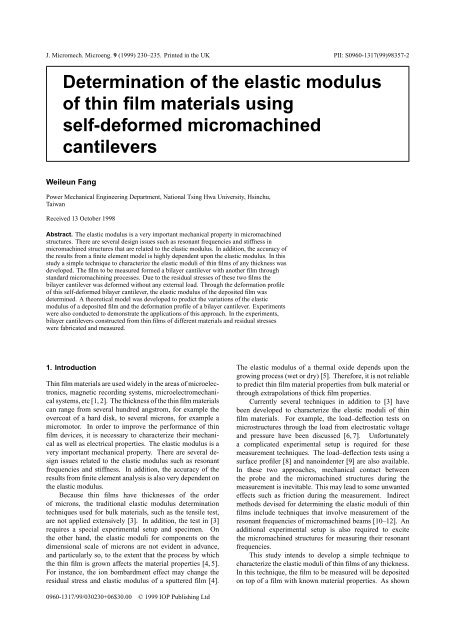
J. Micromech. Microeng. 9 (1999) 230–235. Printed in <strong>the</strong> UK PII: S0960-1317(99)98357-2<strong>Determination</strong> <strong>of</strong> <strong>the</strong> <strong>elastic</strong> <strong>modulus</strong><strong>of</strong> <strong>thin</strong> <strong>film</strong> materials usingself-deformed micromachinedcantileversWeileun FangPower Mechanical Engineering Department, National Tsing Hwa University, Hsinchu,TaiwanReceived 13 October 1998Abstract. The <strong>elastic</strong> <strong>modulus</strong> is a very important mechanical property in micromachinedstructures. There are several design issues such as resonant frequencies and stiffness inmicromachined structures that are related to <strong>the</strong> <strong>elastic</strong> <strong>modulus</strong>. In addition, <strong>the</strong> accuracy <strong>of</strong><strong>the</strong> results from a finite element model is highly dependent upon <strong>the</strong> <strong>elastic</strong> <strong>modulus</strong>. In thisstudy a simple technique to characterize <strong>the</strong> <strong>elastic</strong> moduli <strong>of</strong> <strong>thin</strong> <strong>film</strong>s <strong>of</strong> any thickness wasdeveloped. The <strong>film</strong> to be measured formed a bilayer cantilever with ano<strong>the</strong>r <strong>film</strong> throughstandard micromachining processes. Due to <strong>the</strong> residual stresses <strong>of</strong> <strong>the</strong>se two <strong>film</strong>s <strong>the</strong>bilayer cantilever was deformed without any external load. Through <strong>the</strong> deformation pr<strong>of</strong>ile<strong>of</strong> this self-deformed bilayer cantilever, <strong>the</strong> <strong>elastic</strong> <strong>modulus</strong> <strong>of</strong> <strong>the</strong> deposited <strong>film</strong> wasdetermined. A <strong>the</strong>oretical model was developed to predict <strong>the</strong> variations <strong>of</strong> <strong>the</strong> <strong>elastic</strong><strong>modulus</strong> <strong>of</strong> a deposited <strong>film</strong> and <strong>the</strong> deformation pr<strong>of</strong>ile <strong>of</strong> a bilayer cantilever. Experimentswere also conducted to demonstrate <strong>the</strong> applications <strong>of</strong> this approach. In <strong>the</strong> experiments,bilayer cantilevers constructed from <strong>thin</strong> <strong>film</strong>s <strong>of</strong> different materials and residual stresseswere fabricated and measured.1. IntroductionThin <strong>film</strong> materials are used widely in <strong>the</strong> areas <strong>of</strong> microelectronics,magnetic recording systems, microelectromechanicalsystems, etc [1, 2]. The thickness <strong>of</strong> <strong>the</strong> <strong>thin</strong> <strong>film</strong> materialscan range from several hundred angstrom, for example <strong>the</strong>overcoat <strong>of</strong> a hard disk, to several microns, for example amicromotor. In order to improve <strong>the</strong> performance <strong>of</strong> <strong>thin</strong><strong>film</strong> devices, it is necessary to characterize <strong>the</strong>ir mechanicalas well as electrical properties. The <strong>elastic</strong> <strong>modulus</strong> is avery important mechanical property. There are several designissues related to <strong>the</strong> <strong>elastic</strong> <strong>modulus</strong> such as resonantfrequencies and stiffness. In addition, <strong>the</strong> accuracy <strong>of</strong> <strong>the</strong>results from finite element analysis is also very dependent on<strong>the</strong> <strong>elastic</strong> <strong>modulus</strong>.Because <strong>thin</strong> <strong>film</strong>s have thicknesses <strong>of</strong> <strong>the</strong> order<strong>of</strong> microns, <strong>the</strong> traditional <strong>elastic</strong> <strong>modulus</strong> determinationtechniques used for bulk materials, such as <strong>the</strong> tensile test,are not applied extensively [3]. In addition, <strong>the</strong> test in [3]requires a special experimental setup and specimen. On<strong>the</strong> o<strong>the</strong>r hand, <strong>the</strong> <strong>elastic</strong> moduli for components on <strong>the</strong>dimensional scale <strong>of</strong> microns are not evident in advance,and particularly so, to <strong>the</strong> extent that <strong>the</strong> process by which<strong>the</strong> <strong>thin</strong> <strong>film</strong> is grown affects <strong>the</strong> material properties [4, 5].For instance, <strong>the</strong> ion bombardment effect may change <strong>the</strong>residual stress and <strong>elastic</strong> <strong>modulus</strong> <strong>of</strong> a sputtered <strong>film</strong> [4].The <strong>elastic</strong> <strong>modulus</strong> <strong>of</strong> a <strong>the</strong>rmal oxide depends upon <strong>the</strong>growing process (wet or dry) [5]. Therefore, it is not reliableto predict <strong>thin</strong> <strong>film</strong> material properties from bulk material orthrough extrapolations <strong>of</strong> thick <strong>film</strong> properties.Currently several techniques in addition to [3] havebeen developed to characterize <strong>the</strong> <strong>elastic</strong> moduli <strong>of</strong> <strong>thin</strong><strong>film</strong> materials. For example, <strong>the</strong> load–deflection tests onmicrostructures through <strong>the</strong> load from electrostatic voltageand pressure have been discussed [6, 7]. Unfortunatelya complicated experimental setup is required for <strong>the</strong>semeasurement techniques. The load–deflection tests using asurface pr<strong>of</strong>iler [8] and nanoindenter [9] are also available.In <strong>the</strong>se two approaches, mechanical contact between<strong>the</strong> probe and <strong>the</strong> micromachined structures during <strong>the</strong>measurement is inevitable. This may lead to some unwantedeffects such as friction during <strong>the</strong> measurement. Indirectmethods devised for determining <strong>the</strong> <strong>elastic</strong> moduli <strong>of</strong> <strong>thin</strong><strong>film</strong>s include techniques that involve measurement <strong>of</strong> <strong>the</strong>resonant frequencies <strong>of</strong> micromachined beams [10–12]. Anadditional experimental setup is also required to excite<strong>the</strong> micromachined structures for measuring <strong>the</strong>ir resonantfrequencies.This study intends to develop a simple technique tocharacterize <strong>the</strong> <strong>elastic</strong> moduli <strong>of</strong> <strong>thin</strong> <strong>film</strong>s <strong>of</strong> any thickness.In this technique, <strong>the</strong> <strong>film</strong> to be measured will be depositedon top <strong>of</strong> a <strong>film</strong> with known material properties. As shown0960-1317/99/030230+06$30.00 © 1999 IOP Publishing Ltd
Weileun Fangbilayer cantilever [15],I effective = e 1h 3 (212 + e 1h 2 h 1 + h ) 222 −ȳ( ) 2+ h3 112 + h h112 −ȳȳ= e 1h 2 (h 1 +h 2 /2)+h 2 1 /2 . (4)e 1 h 2 +h 1If <strong>the</strong> thickness <strong>of</strong> <strong>the</strong> <strong>film</strong> to be measured is very small (i.e.h 2 ≪ h 1 ), it is obtained from (3) and (4) that ρ gradient ≈ ρ 1 .The uniform residual stress can be relieved through <strong>the</strong>free end for a single-layer cantilever. However, for a bilayercantilever, it will be exposed to a bending moment by <strong>the</strong>uniform residual stresses if <strong>the</strong> uniform residual strains (ɛ 0 ) 1and (ɛ 0 ) 2 <strong>of</strong> <strong>the</strong> <strong>thin</strong> <strong>film</strong>s are different. After <strong>the</strong> uniformresidual stresses are relieved from <strong>the</strong> <strong>film</strong>s, <strong>the</strong>re are resultantnormal forces P i and moments M i acting over each <strong>film</strong> asshown in figure 3(b). Since no external forces and momentsare applied to <strong>the</strong> <strong>film</strong>s, <strong>the</strong> basic requirement for this bilayercantilever is to satisfy ∑ P = 0 and ∑ M = 0. It is evidentfor this self-deformed structure thatP 1 + P 2 = 0 M 1 + M 2 = P 1h 12 + P 2(h 1 + h )22hence P 1 =−P 2 and M 1 + M 2 = P 2 (h 1 + h 2 )/2. In order tosatisfy <strong>the</strong> equation <strong>of</strong> compatibility, <strong>the</strong> total strain for <strong>film</strong>s1 and 2 must be equal at <strong>the</strong>ir interface. Since <strong>the</strong> cantileveris bent with a radius <strong>of</strong> curvature ρ uniform , <strong>the</strong> compatibilityequation becomes− (σ 0) 2+E 2P 2E 2 h 2 w + h 22ρ uniform=− (σ 0) 1E 1+P 1(5)E 1 h 1 w − h 12ρ uniform(6)where w is <strong>the</strong> width <strong>of</strong> <strong>the</strong> <strong>film</strong>s. Note that <strong>the</strong>re are negativesigns for both (σ 0 ) 1 and (σ 0 ) 2 , since <strong>the</strong>y are residual stresses.The radius <strong>of</strong> curvature ρ uniform determined through (5) and(6) is⎛ρ uniform = ⎝ − 1/e1+H 13 − 1+e1H6(H 1+H1 2 13) 6(1+H − H11)(σ 0 ) 1 − (σ0)2e 12 − 1 2⎞⎠ E 1 h 1 (7)where H 1 = h 2 /h 1 is a non-dimensional parameter.Therefore, <strong>the</strong> net radius <strong>of</strong> curvature <strong>of</strong> <strong>the</strong> bent bilayer beamρ total is1 1 1= + . (8)ρ total ρ gradient ρ uniformSubstitution <strong>of</strong> (3), (4) and (7) into (8) results in <strong>the</strong> followingrelationshipE 2 = f(ρ total ,h 1 ,h 2 ,ρ 1 ,ρ 2 ,(σ 0 ) 1 ,(σ 0 ) 2 ,E 1 ). (9)Therefore, <strong>the</strong> biaxial <strong>elastic</strong> <strong>modulus</strong> E 2 can be determinedthrough (9).3. Applications and resultsIn applications <strong>of</strong> this technique, a PECVD nitride <strong>film</strong> hasbeen used in <strong>the</strong> case studies. Bilayer cantilevers with alength between 40 and 200 µm were fabricated throughconventional bulk micromachining in this experiment.Cantilevers <strong>of</strong> different lengths were used to check <strong>the</strong>uniformity <strong>of</strong> <strong>the</strong> fabrication and <strong>the</strong> repeatability andconsistency <strong>of</strong> <strong>the</strong> measurements. Since <strong>the</strong> materialproperties <strong>of</strong> <strong>the</strong> <strong>the</strong>rmally grown SiO 2 have been extensivelystudied [5, 16, 17], it was chosen as <strong>the</strong> base layer <strong>of</strong> <strong>the</strong>bilayer cantilever. In short, <strong>the</strong> bilayer cantilevers consisted<strong>of</strong> <strong>the</strong>rmal SiO 2 and PECVD nitride. As shown in figures 1(a)and (b), <strong>the</strong> SiO 2 <strong>film</strong> was <strong>the</strong>rmally grown onto a (100)wafer at 1050 ◦ C first and <strong>the</strong>n deposited with a nitride <strong>film</strong>.Both <strong>of</strong> <strong>the</strong>se two <strong>film</strong>s were patterned using lithography andbuffered hydr<strong>of</strong>luoric acid as illustrated in figure 1(c). Thebilayer cantilevers were suspended above a cavity as shown infigure 1(d), after <strong>the</strong> substrate was etched anisotropically withN 2 H 4 . Since <strong>the</strong> selectivity between single crystal siliconand <strong>the</strong> <strong>thin</strong> <strong>film</strong>s is very large for N 2 H 4 , <strong>the</strong> removal <strong>of</strong> <strong>the</strong><strong>thin</strong> <strong>film</strong>s during <strong>the</strong> etching process is negligible. The SEMphotograph in figure 4 shows several typical micromachinedcantilevers.The deformation configuration <strong>of</strong> <strong>the</strong> micromachinedcantilevers was measured quantitatively using an interferrometricpr<strong>of</strong>ilometry. A typical deflection pr<strong>of</strong>ile <strong>of</strong> a bilayermicromachined cantilever measured in this manner is shownin figure 5. Hence <strong>the</strong> radius <strong>of</strong> curvature <strong>of</strong> <strong>the</strong> bilayer cantileverρ total is determined from <strong>the</strong> measured pr<strong>of</strong>iles. Theradius <strong>of</strong> curvature <strong>of</strong> SiO 2 and PECVD nitride single-layercantilevers ρ 1 and ρ 2 were also characterized in <strong>the</strong> samemanner. In addition, <strong>the</strong> residual stresses (σ 0 ) 1 and (σ 0 ) 2 <strong>of</strong><strong>the</strong> <strong>film</strong>s was characterized using a commercialized <strong>thin</strong> <strong>film</strong>stress measurement instrument in this experiment. The residualstresses were determined by measuring <strong>the</strong> change in <strong>the</strong>global curvature <strong>of</strong> a wafer after <strong>the</strong> deposition <strong>of</strong> <strong>the</strong> <strong>thin</strong><strong>film</strong> [18]. In <strong>the</strong> experiment, <strong>the</strong> residual stress (σ 0 ) 1 <strong>of</strong> <strong>film</strong>1 is considered to be unchanged after <strong>the</strong> deposition <strong>of</strong> <strong>film</strong>2. With E 1 , h 1 and h 2 being determined from <strong>the</strong> measuredbiaxial <strong>elastic</strong> moduli and thicknesses, E 2 was found in turnthrough equation (9).In <strong>the</strong> case study, <strong>the</strong> SiO 2 <strong>film</strong> was 0.33 µm thick and<strong>the</strong> PECVD nitride <strong>film</strong> was 0.30 µm thick. Figure 6(a) and(b) shows <strong>the</strong> measured configuration <strong>of</strong> SiO 2 and PECVDnitride single-layer cantilevers, respectively. According to<strong>the</strong> measurements, <strong>the</strong> average radius <strong>of</strong> curvature for SiO 2and PECVD nitride cantilevers were ρ 1 = 360 µm and ρ 2 =780 µm, respectively. In addition, <strong>the</strong> radius <strong>of</strong> curvature<strong>of</strong> <strong>the</strong> bilayer cantilever determined using <strong>the</strong> pr<strong>of</strong>ile infigure 5 was ρ total =−190 µm. The residual stresses <strong>of</strong><strong>the</strong> SiO 2 and PECVD nitride <strong>film</strong>s characterized through<strong>the</strong> wafer curvature approach were (σ 0 ) 1 =−290 MPa and(σ 0 ) 2 =−1120 MPa, respectively. Since <strong>the</strong> <strong>elastic</strong> <strong>modulus</strong>and <strong>the</strong> Poisson’s ratio <strong>of</strong> <strong>the</strong> wet <strong>the</strong>rmal SiO 2 is 70 GPa and0.15, respectively, <strong>the</strong> biaxial <strong>elastic</strong> <strong>modulus</strong> <strong>of</strong> <strong>film</strong> 1 isE 1 = 82 GPa. Therefore, <strong>the</strong> relationship between E 2 andρ total , shown in figure 7, is determined through (9).As indicated in figure 7, <strong>the</strong> bilayer cantilever is initiallybent downward with ρ total = −6 µmatE 2 = 10 GPa.The radius <strong>of</strong> curvature <strong>of</strong> <strong>the</strong> bilayer cantilever is changedto −2000 µm when E 2 is increased to 275 GPa. WhenE 2 is near 300 GPa, ρ total becomes very large; in o<strong>the</strong>rwords, <strong>the</strong> bilayer cantilever is flat. After E 2 is greater than310 GPa, <strong>the</strong> bilayer cantilever is bent upward, and <strong>the</strong> radius232
Self-deformed micromachined cantileversFigure 4. SEM photograph <strong>of</strong> <strong>the</strong> bilayer cantilevers.Figure 5. The measured deformation configuration <strong>of</strong> a 25 µm long bilayer beam from interferometric pr<strong>of</strong>ilometry.<strong>of</strong> curvature <strong>of</strong> <strong>the</strong> bilayer cantilever is decreased when E 2is increased. The configurations <strong>of</strong> <strong>the</strong> bilayer cantilever fordifferent E 2 are also depicted by <strong>the</strong> insets in figure 7. Sinceρ total =−190 µm, <strong>the</strong> biaxial <strong>elastic</strong> <strong>modulus</strong> <strong>of</strong> <strong>the</strong> PECVDnitride <strong>film</strong> in this experiment is E 2 = 182 GPa. Thus <strong>the</strong><strong>elastic</strong> <strong>modulus</strong> <strong>of</strong> <strong>the</strong> PECVD nitride <strong>film</strong> is E f 2 = 137 GPafor <strong>the</strong> Poisson’s ratio <strong>of</strong> PECVD nitride <strong>film</strong> ν f 2 = 0.25 [19].By way <strong>of</strong> comparison with <strong>the</strong> existing results, <strong>the</strong> biaxial<strong>elastic</strong> <strong>modulus</strong> <strong>of</strong> <strong>the</strong> PECVD nitride <strong>film</strong> is distributed from85 GPa to 210 GPa [19].4. DiscussionIn general, micromachined structures are always deformedby <strong>the</strong> <strong>thin</strong> <strong>film</strong> residual stresses. The proposed techniqueexploits this characteristic to determine <strong>the</strong> <strong>elastic</strong> moduli <strong>of</strong><strong>thin</strong> <strong>film</strong>s. The advantages <strong>of</strong> such an approach are tw<strong>of</strong>old:first, <strong>the</strong> structure is self-deformed, hence no complicatedsetup for applying external loads is required; and second, <strong>the</strong>error due to <strong>the</strong> initial deflection during measurement, such as<strong>the</strong> deviation <strong>of</strong> <strong>the</strong> resonant frequencies, can be prevented.Fur<strong>the</strong>rmore, it is recommended to characterize <strong>the</strong> <strong>thin</strong> <strong>film</strong>material properties through multiple approaches in order toreach a reliable result. Thus, <strong>the</strong> existing techniques [5–12],in which <strong>the</strong> <strong>elastic</strong> <strong>modulus</strong> is determined by complicatedsetups, can be supplemented with <strong>the</strong> use <strong>of</strong> <strong>the</strong> bilayercantilever technique.The results according to <strong>the</strong> simulations <strong>of</strong> <strong>thin</strong> <strong>film</strong>swith h 2 = 0.1 µm and 0.3 µm thick Si 3 N 4 <strong>film</strong> depositedonto a h 1 = 1 µm thick SiO 2 base layer is shown in figure 8.The three different curves in figure 8 represent <strong>the</strong> variations<strong>of</strong> E 2 and ρ total for radii <strong>of</strong> curvature ρ 2 = 780 µm, 7800 µmand −780 µm, respectively. In comparisons with <strong>the</strong> resultsshown in figures 8(a) and (b), it is evident that <strong>the</strong> relationshipbetween ρ total and E 2 will not be influenced by ρ 2 for smallerh 2 . Thus, it is not necessary to characterize <strong>the</strong> radius <strong>of</strong>233
Weileun FangFigure 6. The measured deformation configuration <strong>of</strong>: (a) a SiO 2cantilever; and (b) a PECVD nitride cantilever.Figure 8. The variation <strong>of</strong> E 2 and ρ total for three different radii <strong>of</strong>curvature ρ 2 when <strong>the</strong> <strong>film</strong> thickness h 2 is: (a) 0.3 µm; and(b) 0.1 µm.Figure 7. The variation <strong>of</strong> <strong>the</strong> biaxial <strong>elastic</strong> <strong>modulus</strong> E 2 and <strong>the</strong>radius <strong>of</strong> curvature <strong>of</strong> <strong>the</strong> bilayer beam ρ total .curvature ρ 2 when <strong>the</strong> thickness <strong>of</strong> <strong>the</strong> <strong>film</strong> h 2 is very <strong>thin</strong>.The difficulty in determining <strong>the</strong> gradient residual stress <strong>of</strong><strong>film</strong> 2 when h 2 is very <strong>thin</strong> can be prevented.The residual stresses (σ 0 ) 1 and (σ 0 ) 2 <strong>of</strong> <strong>the</strong> <strong>thin</strong> <strong>film</strong>swere determined through <strong>the</strong> variations <strong>of</strong> <strong>the</strong> wafer curvaturein this study. This approach only gives an average measure<strong>of</strong> <strong>the</strong> stress across <strong>the</strong> entire substrate. In addition, <strong>the</strong>irregular surface topology <strong>of</strong> <strong>the</strong> substrate may lead to anerror in stress measurement. Therefore errors <strong>of</strong> <strong>the</strong> biaxial<strong>elastic</strong> <strong>modulus</strong> E 2 determined through (9) are produced by<strong>the</strong> error <strong>of</strong> <strong>the</strong> measured residual stress (σ 0 ) 2 . For instance,<strong>the</strong> error propagation between (σ 0 ) 2 and E 2 is(dE 2E 1 h 1= −E 2 6ρ total (σ 0 ) 2 (H 1 + H1 2)E 1 h 1 e1 2 +H 13 ) −16ρ total (σ 0 ) 2 (1+H 1 ) +1 d(σ0 ) 2. (10)(σ 0 ) 2It is obvious from (10) that a limiting case <strong>of</strong> <strong>the</strong> errorpropagation is dE 2 /E 2 ≈ d(σ 0 ) 2 /(σ 0 ) 2 . In order to prevent<strong>the</strong> error <strong>of</strong> <strong>the</strong> <strong>elastic</strong> <strong>modulus</strong> due to <strong>the</strong> measurement <strong>of</strong>(σ 0 ) 1 and (σ 0 ) 2 <strong>of</strong> <strong>the</strong> <strong>thin</strong> <strong>film</strong>s, (7) can be rewritten as⎛ρ uniform = ⎝ − 1/e1+H 13 − 1+e1H6(H 1+H1 2 13) 6(1+H − H11) 2 − ⎞12⎠ h 1 . (11)(ε 0 ) 1 − (ε 0 ) 2In (11), <strong>the</strong> residual strains (ε 0 ) 1 and (ε 0 ) 2 <strong>of</strong> <strong>the</strong> <strong>thin</strong> <strong>film</strong>s isused to replace <strong>the</strong> residual stresses <strong>of</strong> <strong>the</strong> <strong>thin</strong> <strong>film</strong>s. Since<strong>the</strong> residual strains can be determined through diagnosticmicromachined beams [13], a more accurate measured value234
Self-deformed micromachined cantileversFigure 9. Fabrication processes <strong>of</strong> <strong>the</strong> bilayer cantilever through:(a) <strong>the</strong> fabrication <strong>of</strong> a single-layer cantilever; and (b) <strong>the</strong>deposition <strong>of</strong> a second <strong>thin</strong> <strong>film</strong>.can be obtained. Moreover, <strong>the</strong> distribution <strong>of</strong> <strong>the</strong> residualstrain can also be measured through <strong>the</strong> same approach.However, this approach cannot be applied for a very <strong>thin</strong> <strong>film</strong>.In <strong>the</strong> presented case, <strong>the</strong> <strong>thin</strong> <strong>film</strong>s <strong>of</strong> <strong>the</strong>bilayer cantilever were patterned first and <strong>the</strong>n undercutsimultaneously as shown in figures 1(c) and 1(d). Thisis different from <strong>the</strong> case discussed in [20], where <strong>film</strong> 2was deposited after <strong>the</strong> cantilevers made from <strong>film</strong> 1 werefabricated as shown in figure 9. Therefore <strong>the</strong> uniformresidual stress <strong>of</strong> <strong>film</strong> 1 has no contribution to <strong>the</strong> bending<strong>of</strong> <strong>the</strong> bilayer cantilever in [20]. In o<strong>the</strong>r words, (9) isnot appropriate for determining <strong>the</strong> biaxial <strong>elastic</strong> moduli<strong>of</strong> <strong>thin</strong> <strong>film</strong>s fabricated through <strong>the</strong> processes illustrated infigure 9.AcknowledgmentsThis material is based (in part) upon work supported by<strong>the</strong> National Science Council (Taiwan) under Grant NSC87-2218-E007-007. The author would also like to expresshis appreciation for <strong>the</strong> assistance <strong>of</strong> his graduate studentsJerwei Hsieh, Hung-Yi Lin and Hsing-Hua Hu <strong>of</strong> NationalTsing Hua University (Taiwan) in handling <strong>the</strong> fabricationprocesses.References[1] Petersen K E 1982 Silicon as a mechanical material Proc.IEEE 70 420–57[2] Nix W D 1991 Mechanical properties <strong>of</strong> <strong>thin</strong> <strong>film</strong>s Metall.Trans. A 20 2217–45[3] SharpeWNJr,YuanBandEdwards R L 1997 A newtechnique for measuring <strong>the</strong> mechanical properties <strong>of</strong> <strong>thin</strong><strong>film</strong>s J. Microelectromech. Syst. 6 193–9[4] Thornton J A and H<strong>of</strong>fman D W 1989 Stress-related effectsin <strong>thin</strong> <strong>film</strong> Thin Solid Films 171 5–31[5] Petersen K E and Guarnieri C R 1979 Young’s <strong>modulus</strong>measurements <strong>of</strong> <strong>thin</strong> <strong>film</strong>s using micromechanics J. Appl.Phys. 50 6761–5[6] Najafi K and Suzuki K 1989 A novel technique and structurefor <strong>the</strong> measurement <strong>of</strong> intrinsic stress and Young’s<strong>modulus</strong> <strong>of</strong> <strong>thin</strong> <strong>film</strong>s Proc. IEEE/MEMS (Salt Lake City,UT, February 1989) pp 96–7[7] Tabata O, Kawahata K, Sugiyama S and Igarashi I 1989Mechanical property measurements <strong>of</strong> <strong>thin</strong> <strong>film</strong>s usingload–deflection <strong>of</strong> composite rectangular membraneSensors Actuators A 20 135–41[8] Tai Y-C and Muller R S 1990 Measurement <strong>of</strong> Young’s<strong>modulus</strong> on micr<strong>of</strong>abricated structures using a surfacepr<strong>of</strong>iler Proc. IEEE/MEMS (Napa Valley, CA, February1990) pp 11–14[9] Doerner M F and Nix W D 1986 A method for interpreting<strong>the</strong> data from depth-sensing indentation instrumentsJ. Mater. Res. 1 601–9[10] Kiesewetter L, Zhang J-M, Houdeau D and Steckenborn A1992 <strong>Determination</strong> <strong>of</strong> Young’s moduli <strong>of</strong>micromechanical <strong>thin</strong> <strong>film</strong>s using <strong>the</strong> resonance methodSensors Actuators A 35 153–9[11] Zhang L M, Uttamchandani D and Culshaw B 1991Measurement <strong>of</strong> <strong>the</strong> mechanical properties <strong>of</strong> siliconmicroresonators Sensors Actuators A, 29 79–84[12] Zhang L M, Uttamchandani D, Culshaw B and Dobson P1990 Measurement <strong>of</strong> Young’s <strong>modulus</strong> and internalstress in silicon microresonators using a resonantfrequency technique Meas. Sci. Technol. 1 1343–6[13] Fang W and Wickert J A 1996 Determining mean andgradient residual stresses in <strong>thin</strong> <strong>film</strong>s usingmicromachined cantilevers J. Micromech. Microeng. 6301–9[14] Chu W-H, Mehregany M and Mullen R L 1993 Analysis <strong>of</strong>tip deflection and force <strong>of</strong> a bimetallic cantilevermicroactuator J. Micromech. Microeng. 3 4–7[15] Beer F P and Johnston ERJr1981 Mechanics <strong>of</strong> Materials(New York: McGraw-Hill)[16] Jaccodine R J and Schlegel W A 1966 Measurement <strong>of</strong>strains at Si–SiO 2 interface J. Appl. Phys. 37 2429–34[17] Wolf S and Tauber R N 1986 Silicon Processing (SunsetBeach, CA: Lattice)[18] Rossnagel S M, Gilstrap P and Rujkorakarn R 1982 Stressmeasurement in <strong>thin</strong> <strong>film</strong>s by geometrical optics J. Vac.Sci. Technol. B 21 1045–6[19] St<strong>of</strong>fel A, Kovacs A, Kronast W and Muller B 1996 LPCVDagainst PECVD for micromechanical applicationsJ. Micromech. Microeng. 6 1–13[20] Fang W and Wickert J A 1995 Comments on measuring<strong>thin</strong>-<strong>film</strong> stresses using bi-layer micromachined beamsJ. Micromech. Microeng. 5 276–81235