Improvement of Specimen Preparation Process for Bulge Test Using ...
Improvement of Specimen Preparation Process for Bulge Test Using ...
Improvement of Specimen Preparation Process for Bulge Test Using ...

Create successful ePaper yourself
Turn your PDF publications into a flip-book with our unique Google optimized e-Paper software.
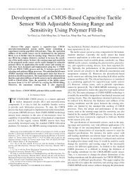
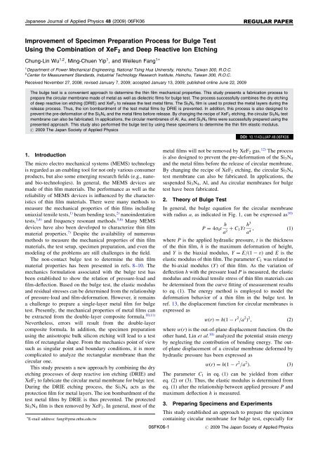
Japanese Journal <strong>of</strong> Applied Physics 48 (2009) 06FK06REGULAR PAPER<strong>Improvement</strong> <strong>of</strong> <strong>Specimen</strong> <strong>Preparation</strong> <strong>Process</strong> <strong>for</strong> <strong>Bulge</strong> <strong>Test</strong><strong>Using</strong> the Combination <strong>of</strong> XeF 2 and Deep Reactive Ion EtchingChung-Lin Wu 1;2 , Ming-Chuen Yip 1 , and Weileun Fang 11 Department <strong>of</strong> Power Mechanical Engineering, National Tsing Hua Uninersity, Hsinchu, Taiwan 300, R.O.C.2 Center <strong>for</strong> Measurement Standards, Industrial Technology Research Institute, Hsinchu, Taiwan 300, R.O.C.Received November 27, 2008; revised January 7, 2009; accepted January 13, 2009; published online June 22, 2009The bulge test is a convenient approach to determine the thin film mechanical properties. This study presents a fabrication process toprepare the circular membrane made <strong>of</strong> metal as well as dielectric films <strong>for</strong> bulge test. The process successfully combines the dry etching<strong>of</strong> deep reactive ion etching (DRIE) and XeF 2 to release the test metal films. The Si 3 N 4 film is used to protect the metal layers during therelease process. Thus, the ion bombardment <strong>of</strong> the test metal films by DRIE is prevented. In addition, this process is also designed toprevent the pre-de<strong>for</strong>mation <strong>of</strong> the Si 3 N 4 and the metal films be<strong>for</strong>e release. By changing the recipe <strong>of</strong> XeF 2 etching, the circular Si 3 N 4 testmembrane can also be fabricated. In applications, the circular membranes <strong>of</strong> Al, Au, and Si 3 N 4 films were successfully prepared using thepresented approach. This study also per<strong>for</strong>med the bulge test by using these specimens to determine the thin film elastic modulus.# 2009 The Japan Society <strong>of</strong> Applied Physics1. IntroductionThe micro electro mechanical systems (MEMS) technologyis regarded as an enabling tool <strong>for</strong> not only various consumerproducts, but also some emerging research fields (e.g., nanoandbio-technologies). In general, the MEMS devices aremade <strong>of</strong> thin film materials. The per<strong>for</strong>mance as well as thereliability <strong>of</strong> MEMS devices is influenced by the characteristics<strong>of</strong> thin film materials. There were many methods tomeasure the mechanical properties <strong>of</strong> thin films includinguniaxial tensile tests, 1) beam bending tests, 2) nanoindentationtests, 3,4) and frequency resonant methods. 5,6) Many MEMSdevices have also been developed to characterize thin filmmaterial properties. 7) Despite the availability <strong>of</strong> numerousmethods to measure the mechanical properties <strong>of</strong> thin filmmaterials, the test setup, specimen preparation, and even themodeling <strong>of</strong> the problems are still challenges in the field.The non-contact bulge test to determine the thin filmmaterial properties has been presented in refs. 8–10. Themechanics <strong>for</strong>mulation associated with the bulge test hasbeen established to show the relation <strong>of</strong> pressure-load andfilm-deflection. Based on the bulge test, the elastic modulusand residual stresses can be determined from the relationship<strong>of</strong> pressure-load and film-de<strong>for</strong>mation. However, it remainsa challenge to prepare a single-layer metal film <strong>for</strong> bulgetest. Presently, the mechanical properties <strong>of</strong> metal films canbe extracted from the double-layer composite <strong>for</strong>mula. 10,11)Nevertheless, errors will result from the double-layercomposite <strong>for</strong>mula. In addition, the specimen preparationusing the anisotropic bulk silicon etching will lead to a testfilm <strong>of</strong> rectangular shape. From the mechanics point <strong>of</strong> viewsuch as singular point and boundary conditions, it is morecomplicated to analyze the rectangular membrane than thecircular one.This study presents a new approach by combining the dryetching processes <strong>of</strong> deep reactive ion etching (DRIE) andXeF 2 to fabricate the circular metal membrane <strong>for</strong> bulge test.During the DRIE etching process, the Si 3 N 4 acts as theprotection film <strong>for</strong> metal layers. The ion bombardment <strong>of</strong> thetest metal films by DRIE is thus prevented. The protectedSi 3 N 4 film is then removed by XeF 2 . In general, most <strong>of</strong> the E-mail address: fang@pme.nthu.edu.tw06FK06-1DOI: 10.1143/JJAP.48.06FK06metal films will not be removed by XeF 2 gas. 12) The processis also designed to prevent the pre-de<strong>for</strong>mation <strong>of</strong> the Si 3 N 4and the metal films be<strong>for</strong>e the release <strong>of</strong> circular membrane.By changing the recipe <strong>of</strong> XeF 2 etching, the circular Si 3 N 4test membrane can also be fabricated. In applications, thesuspended Si 3 N 4 , Al, and Au circular membranes <strong>for</strong> bulgetest have been fabricated.2. Theory <strong>of</strong> <strong>Bulge</strong> <strong>Test</strong>In general, the bulge equation <strong>for</strong> the circular membranewith radius a, as indicated in Fig. 1, can be expressed as 10)P ¼ 4 0 t h a þ C 1Yt h32 a ;ð1Þ4where P is the applied hydraulic pressure, t is the thickness<strong>of</strong> the thin film, h is the maximum de<strong>for</strong>mation <strong>of</strong> height,and Y is the biaxial modulus, Y ¼ E=ð1 vÞ and E is theelastic modulus <strong>of</strong> thin film. The parameter C 1 was related tothe bi-axial modulus (Y) <strong>of</strong> thin film. As the variation <strong>of</strong>deflection h with the pressure load P is measured, the elasticmodulus and residual tensile stress <strong>of</strong> thin film materials canbe determined from the curve fitting <strong>of</strong> measurement resultsto eq. (1). The energy method is employed to model thede<strong>for</strong>mation behavior <strong>of</strong> a thin film in the bulge test. Inref. 13, the displacement function <strong>for</strong> circular membranes isexpressed aswðrÞ ¼hð1 r 2 =a 2 Þ 2 ; ð2Þwhere wðrÞ is the out-<strong>of</strong>-plane displacement function. On theother hand, Lin et al. 10) analyzed the potential strain energyby neglecting the contribution <strong>of</strong> bending energy. The out<strong>of</strong>-planedisplacement <strong>of</strong> a circular membrane de<strong>for</strong>med byhydraulic pressure has been expressed aswðrÞ ¼hð1 r 2 =a 2 Þ: ð3ÞThe parameter C 1 in eq. (1) can be yielded from eithereq. (2) or (3). Thus, the elastic modulus is determined fromeq. (1) after the relationship between applied pressure P andmaximum deflection h is measured.3. Preparing <strong>Specimen</strong>s and ExperimentsThis study established an approach to prepare the specimencontaining circular membrane <strong>for</strong> bulge test, especially <strong>for</strong># 2009 The Japan Society <strong>of</strong> Applied Physics
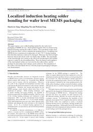
Jpn. J. Appl. Phys. 48 (2009) 06FK06C.-L. Wu et al.InterferometerNeedle valuePneumatic valuePressure sensor(a)Fig. 5.(Color online) The experimental setup <strong>for</strong> bulge test.(b)(c)Fig. 3. (Color online) The photos <strong>of</strong> typical fabricated specimenswith, (a) Al, (b) Au, and (c) Si 3 N 4 thin film circular membranes.Fig. 4. (Color online) The photos to show the front- and back-sideviews <strong>of</strong> the bulge test specimen prepared using the presentedprocess.<strong>of</strong> transparent nitride film was the MP100-ME system(Labguide, with 1 nm readout). The interferometer systemwas used to measure the thickness <strong>of</strong> opaque metal06FK06-3films. The diameter <strong>of</strong> circular membranes can be obtainedby measuring microscopes (Olympus STM6, with 0.1 mmreadout).As a comparison, the mechanical properties <strong>of</strong> thin filmdetermined by a commercial nano-indenter (MTS) are alsopresented. The nano-indenter has a <strong>for</strong>ce resolution <strong>of</strong> 50 nNand a displacement resolution <strong>of</strong> less than 0.01 nm. Adiamond tip <strong>of</strong> the Berkovich type was employed <strong>for</strong> theindentation test. In detail, the nanoindentation was per<strong>for</strong>medby setting a 4 4 array test. There were sixteenexperimental data <strong>for</strong> each thin film in this article. Theaverage elastic modulus <strong>of</strong> thin films was obtained fromthese experimental data. The elastic modulus <strong>of</strong> the specimen,E, can be determined from the reduced modulus, E r : 3)1¼ 1 2þ 1 2 i; ð4ÞE r E E iwhere is the Poisson’s ratio <strong>for</strong> the testing material; E i and i are the elastic modulus and the Poisson’s ratio <strong>of</strong> thematerial <strong>of</strong> indenter, respectively. In this study, E i ¼ 1141GPa and i ¼ 0:07 are used <strong>for</strong> the diamond tip.4. Results and DiscussionThe corresponding relations between pressure and de<strong>for</strong>mationpr<strong>of</strong>ile <strong>of</strong> the fabricated circular membrane <strong>for</strong> Al, Au,and Si 3 N 4 thin films are shown in Figs. 6–8, respectively.These figures also show the measured optical interferencepatterns <strong>of</strong> membranes. Thus, the maximum displacements<strong>of</strong> the membrane at different pressure loads can be obtained.As indicated in Fig. 6, the circular Al membrane has aninitial de<strong>for</strong>mation (as P at atm) due to the thin film residualstress. The deflection shape <strong>of</strong> Al film was influenced by itsresidual stress when P
Jpn. J. Appl. Phys. 48 (2009) 06FK06C.-L. Wu et al.(a)(a)(b)(b)Fig. 7. (Color online) The variation <strong>of</strong> (a) interference fringe patterns,and (b) deflection pr<strong>of</strong>iles, <strong>of</strong> Au film under different pressure.Fig. 6. (Color online) The variation <strong>of</strong> (a) interference fringe patterns,and (b) deflection pr<strong>of</strong>iles, <strong>of</strong> Al film under different pressure.three specimens containing Al membrane <strong>of</strong> differentdiameter. In addition, Figs. 11 and 12 respectively showthe measurement results <strong>for</strong> Au, and Si 3 N 4 films. The elasticmodulus <strong>of</strong> thin film was determined from the curve fitting<strong>of</strong> eq. (1) to the measurement results <strong>of</strong> in Figs. 10–12.According to Lin’s membrane displacement function ineq. (3), the parameter C 1 in eq. (1) is determined asC 1 ¼ð7 Þ=3. The elastic modulus <strong>of</strong> Al film was121:72 8:95 GPa, as the Poisson’s ratio <strong>of</strong> 0.25. Similarly,the elastic modulus <strong>of</strong> Au film was 93:02 5:15 GPa, as thePoisson’s ratio <strong>of</strong> 0.42; and the elastic modulus <strong>of</strong> Si 3 N 4 filmwas 250:92 22:54 GPa, as the Poisson’s ratio <strong>of</strong> 0.25.According to Lin’s model, the elastic modulus is proportionedto ð1 Þ=ð7 Þ. As the Poisson’s ratio has a 20%deviation (i.e. 0:25 0:05), the extracted elastic moduluspossess a near 6% variation.The nano-indentation test was used to confirm themeasured elastic modulus. Figure 13 shows the typicalloading and unloading curves <strong>of</strong> metal films. According tothe measurements, the average elastic modulus <strong>of</strong> Al film06FK06-4was 118.87 GPa as ¼ 0:25 (from bulk material). Theaverage elastic modulus <strong>of</strong> Au film was 92.35 GPa as ¼0:42 (from bulk material). According to eq. (4), the elasticmodulus <strong>of</strong> thin film determined from this approach isproportioned to (1 2 ). As the Poisson’s ratio has a 20%deviation (i.e., 0:25 0:05), the elastic modulus extractedfrom eq. (4) has a less than 3% variation.In comparison, the elastic modulus <strong>of</strong> Al thin film has a2.34% deviation between the values determined from thebulge and nanoindentation tests when ¼ 0:25. Moreover,the elastic modulus <strong>of</strong> Au thin film has a 0.72% deviationbetween the values determined from the bulge and nanoindentationtests when ¼ 0:42. Despite another less than10% deviations could be induced from the variation <strong>of</strong> thePoisson’s ratio, the elastic modulus <strong>of</strong> metal thin filmdetermined from these two approaches agrees well. Insummary, the present dry etching release process is afeasible approach to implement circular metal membrane <strong>for</strong>bulge test.5. ConclusionsThe main contribution <strong>of</strong> this study is to establish a new# 2009 The Japan Society <strong>of</strong> Applied Physics
Jpn. J. Appl. Phys. 48 (2009) 06FK06C.-L. Wu et al.(a)(a)(b)(b)Fig. 8. (Color online) The variation <strong>of</strong> (a) interference fringe patterns,and (b) deflection pr<strong>of</strong>iles, <strong>of</strong> Si 3 N 4 film under different pressure.fabrication process to manufacture the free-standing singlelayercircular membranes <strong>of</strong> metal films. The processsuccessfully combines the dry etching <strong>of</strong> DRIE and XeF 2to release the test metal films. During the release process, themetal films are protected by the Si 3 N 4 layer. As a result, thetest metal films will not experience the ion bombardment byDRIE. In addition, this process is also designed to preventthe pre-de<strong>for</strong>mation <strong>of</strong> the Si 3 N 4 and the metal films be<strong>for</strong>erelease. Thus, the mechanical properties <strong>of</strong> the test film willnot be changed during the processes <strong>for</strong> specimen preparation.The circular Si 3 N 4 test membrane can also befabricated by changing the recipe <strong>of</strong> XeF 2 etching. Inapplications, the circular membranes <strong>of</strong> Al, Au, and Si 3 N 4films were fabricated and then characterized by bulge test.The results also confirmed with the measurements fromnano-indentation test.AcknowledgementsThis research is based on the work supported by NationalScience Council <strong>of</strong> Taiwan under grant <strong>of</strong> NSC-94-2212-E-06FK06-5Fig. 9. (Color online) Comparison <strong>of</strong> the measured and predicteddeflection pr<strong>of</strong>iles <strong>of</strong> circular membranes by pressure load, (a) Al, (b)Au, and (c) Si 3 N 4 thin film circular membranes.007-018. The author would like to express his appreciationto the Center <strong>for</strong> Nano-Science and Technology in theUniversity System <strong>of</strong> Taiwan (Taiwan) <strong>for</strong> providingfabrication facilities.(c)# 2009 The Japan Society <strong>of</strong> Applied Physics
Jpn. J. Appl. Phys. 48 (2009) 06FK06C.-L. Wu et al.(a)Fig. 10. (Color online) Variation <strong>of</strong> pressure and film-displacement<strong>for</strong> three Al film specimens during bulge test.(b)Fig. 13. (Color online) Typical load/displacement curves fromnano-indentation tests: (a) Al film and (b) Au film.Fig. 11. (Color online) Variation <strong>of</strong> pressure and film-displacement<strong>for</strong> three Au film specimens during bulge test.Fig. 12. (Color online) Variation <strong>of</strong> pressure and film-displacement<strong>for</strong> three Si 3 N 4 film specimens during bulge test.1) W. N. Sharpe Jr., B. Yuan, and R. L. Edwards: J. Microelectromech.Syst. 6 (1997) 193.2) G. L. Pearson, W. T. Read, Jr., and W. L. Feldmann: Acta Metall. 5(1957) 181.3) W. C. Oliver and G. M. Pharr: J. Mater. Res. 7 (1992) 1564.4) G. M. Pharr, W. C. Oliver, and F. R. Brotzen: J. Mater. Res. 7 (1992)613.5) H. C. Tsai and W. Fang: Sens. Actuators A 103 (2003) 377.6) W. Van Arsdell and S. B. Brown: Proc. MEMS ASME Int. MechanicalEngineering Congr. Expo., 1998, p. 267.7) K. Sato, M. Shikida, M. Yamasaki, and T. Yoshioka: Proc. MEMS’96,1996, p. 11.8) J. W. Beams: in Structure and Properties <strong>of</strong> Thin Films, ed. C. A.Neugebauer (Wiley, New York, 1959) p. 183.9) M. K. Small and W. D. Nix: J. Mater. Res. 7 (1992) 1553.10) P. Lin: Dr. Thesis, Massachusetts Institute <strong>of</strong> Technology, Cambridge,MA, U.S.A. (1990).11) A. Karimi, O. R. Shojaei, T. Kruml, and J. L. Martin: Thin Solid Films308–309 (1997) 334.12) K. R. Williams and R. S. Muler: J. Microelectromech. Syst. 5 (1996)256.13) S. Timoshenko and S. Woinowsky-Krieger: Theory <strong>of</strong> Plates andShells (McGraw-Hill, New York, 1959).06FK06-6# 2009 The Japan Society <strong>of</strong> Applied Physics