Implementation of a micro ball lens on a silicon optical bench using ...
Implementation of a micro ball lens on a silicon optical bench using ...
Implementation of a micro ball lens on a silicon optical bench using ...

Create successful ePaper yourself
Turn your PDF publications into a flip-book with our unique Google optimized e-Paper software.
IOP PUBLISHING<br />
JOURNAL OF MICROMECHANICS AND MICROENGINEERING<br />
J. Micromech. Microeng. 20 (2010) 085015 (7pp) doi:10.1088/0960-1317/20/8/085015<br />
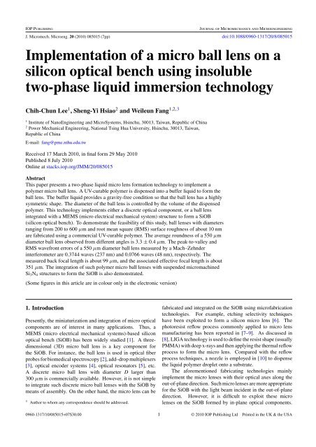
<str<strong>on</strong>g>Implementati<strong>on</strong></str<strong>on</strong>g> <str<strong>on</strong>g>of</str<strong>on</strong>g> a <str<strong>on</strong>g>micro</str<strong>on</strong>g> <str<strong>on</strong>g>ball</str<strong>on</strong>g> <str<strong>on</strong>g>lens</str<strong>on</strong>g> <strong>on</strong> a<br />
silic<strong>on</strong> <strong>optical</strong> <strong>bench</strong> <strong>using</strong> insoluble<br />
two-phase liquid immersi<strong>on</strong> technology<br />
Chih-Chun Lee 1 , Sheng-Yi Hsiao 2 and Weileun Fang 1,2,3<br />
1 Institute <str<strong>on</strong>g>of</str<strong>on</strong>g> NanoEngineering and MicroSystems, Hsinchu, 30013, Taiwan, Republic <str<strong>on</strong>g>of</str<strong>on</strong>g> China<br />
2 Power Mechanical Engineering, Nati<strong>on</strong>al Tsing Hua University, Hsinchu, 30013, Taiwan,<br />
Republic <str<strong>on</strong>g>of</str<strong>on</strong>g> China<br />
E-mail: fang@pme.nthu.edu.tw<br />
Received 17 March 2010, in final form 29 May 2010<br />
Published 8 July 2010<br />
Online at stacks.iop.org/JMM/20/085015<br />
Abstract<br />
This paper presents a two-phase liquid <str<strong>on</strong>g>micro</str<strong>on</strong>g> <str<strong>on</strong>g>lens</str<strong>on</strong>g> formati<strong>on</strong> technology to implement a<br />
polymer <str<strong>on</strong>g>micro</str<strong>on</strong>g> <str<strong>on</strong>g>ball</str<strong>on</strong>g> <str<strong>on</strong>g>lens</str<strong>on</strong>g>. A UV-curable polymer is dispensed into a buffer liquid to form the<br />
<str<strong>on</strong>g>ball</str<strong>on</strong>g> <str<strong>on</strong>g>lens</str<strong>on</strong>g>. The buffer liquid provides a gravity-free c<strong>on</strong>diti<strong>on</strong> so that the <str<strong>on</strong>g>ball</str<strong>on</strong>g> <str<strong>on</strong>g>lens</str<strong>on</strong>g> has a highly<br />
symmetric shape. The diameter <str<strong>on</strong>g>of</str<strong>on</strong>g> the <str<strong>on</strong>g>ball</str<strong>on</strong>g> <str<strong>on</strong>g>lens</str<strong>on</strong>g> is c<strong>on</strong>trolled by the volume <str<strong>on</strong>g>of</str<strong>on</strong>g> the dispensed<br />
polymer. This technology implements either a discrete <strong>optical</strong> comp<strong>on</strong>ent, or a <str<strong>on</strong>g>ball</str<strong>on</strong>g> <str<strong>on</strong>g>lens</str<strong>on</strong>g><br />
integrated with a MEMS (<str<strong>on</strong>g>micro</str<strong>on</strong>g> electrical mechanical system) structure to form a SiOB<br />
(silic<strong>on</strong> <strong>optical</strong> <strong>bench</strong>). To dem<strong>on</strong>strate the feasibility <str<strong>on</strong>g>of</str<strong>on</strong>g> this study, <str<strong>on</strong>g>ball</str<strong>on</strong>g> <str<strong>on</strong>g>lens</str<strong>on</strong>g>es with diameters<br />
ranging from 200 to 600 μm and root mean square (RMS) surface roughness <str<strong>on</strong>g>of</str<strong>on</strong>g> about 10 nm<br />
are fabricated <strong>using</strong> a commercial UV-curable polymer. The average roundness <str<strong>on</strong>g>of</str<strong>on</strong>g> a 550 μm<br />
diameter <str<strong>on</strong>g>ball</str<strong>on</strong>g> <str<strong>on</strong>g>lens</str<strong>on</strong>g> observed from different angles is 3.3 ± 0.4 μm. The peak-to-valley and<br />
RMS wavefr<strong>on</strong>t errors <str<strong>on</strong>g>of</str<strong>on</strong>g> a 550 μm diameter <str<strong>on</strong>g>ball</str<strong>on</strong>g> <str<strong>on</strong>g>lens</str<strong>on</strong>g> measured by a Mach–Zehnder<br />
interferometer are 0.3744 waves (237 nm) and 0.0766 waves (48 nm), respectively. The<br />
measured back focal length is about 99 μm, and the associated effective focal length is about<br />
351 μm. The integrati<strong>on</strong> <str<strong>on</strong>g>of</str<strong>on</strong>g> such polymer <str<strong>on</strong>g>micro</str<strong>on</strong>g> <str<strong>on</strong>g>ball</str<strong>on</strong>g> <str<strong>on</strong>g>lens</str<strong>on</strong>g>es with suspended <str<strong>on</strong>g>micro</str<strong>on</strong>g>machined<br />
Si 3 N 4 structures to form the SiOB is also dem<strong>on</strong>strated.<br />
(Some figures in this article are in colour <strong>on</strong>ly in the electr<strong>on</strong>ic versi<strong>on</strong>)<br />
1. Introducti<strong>on</strong><br />
Presently, the miniaturizati<strong>on</strong> and integrati<strong>on</strong> <str<strong>on</strong>g>of</str<strong>on</strong>g> <str<strong>on</strong>g>micro</str<strong>on</strong>g> <strong>optical</strong><br />
comp<strong>on</strong>ents are <str<strong>on</strong>g>of</str<strong>on</strong>g> interest in many applicati<strong>on</strong>s. Thus, a<br />
MEMS (<str<strong>on</strong>g>micro</str<strong>on</strong>g> electrical mechanical systems)-based silic<strong>on</strong><br />
<strong>optical</strong> <strong>bench</strong> (SiOB) has been widely studied [1]. A threedimensi<strong>on</strong>al<br />
(3D) <str<strong>on</strong>g>micro</str<strong>on</strong>g> <str<strong>on</strong>g>ball</str<strong>on</strong>g> <str<strong>on</strong>g>lens</str<strong>on</strong>g> is a key comp<strong>on</strong>ent for<br />
the SiOB. For instance, the <str<strong>on</strong>g>ball</str<strong>on</strong>g> <str<strong>on</strong>g>lens</str<strong>on</strong>g> is used in <strong>optical</strong> fiber<br />
probes for biomedical spectroscopy [2], add–drop multiplexers<br />
[3], <strong>optical</strong> encoder systems [4], <strong>optical</strong> res<strong>on</strong>ators [5], etc.<br />
A discrete <str<strong>on</strong>g>micro</str<strong>on</strong>g> <str<strong>on</strong>g>ball</str<strong>on</strong>g> <str<strong>on</strong>g>lens</str<strong>on</strong>g> with diameter D larger than<br />
300 μm is commercially available. However, it is not simple<br />
to integrate such discrete <str<strong>on</strong>g>micro</str<strong>on</strong>g> <str<strong>on</strong>g>ball</str<strong>on</strong>g> <str<strong>on</strong>g>lens</str<strong>on</strong>g>es with the SiOB by<br />
means <str<strong>on</strong>g>of</str<strong>on</strong>g> assembly. On the other hand, the <str<strong>on</strong>g>micro</str<strong>on</strong>g> <str<strong>on</strong>g>lens</str<strong>on</strong>g> can be<br />
3 Author to whom any corresp<strong>on</strong>dence should be addressed.<br />
fabricated and integrated <strong>on</strong> the SiOB <strong>using</strong> micr<str<strong>on</strong>g>of</str<strong>on</strong>g>abricati<strong>on</strong><br />
technologies. For example, etching selectivity techniques<br />
have been exploited to form a silic<strong>on</strong> <str<strong>on</strong>g>micro</str<strong>on</strong>g> <str<strong>on</strong>g>lens</str<strong>on</strong>g> [6]. The<br />
photoresist reflow process comm<strong>on</strong>ly applied to <str<strong>on</strong>g>micro</str<strong>on</strong>g> <str<strong>on</strong>g>lens</str<strong>on</strong>g><br />
manufacturing has been reported in [7–9]. As discussed in<br />
[8], LIGA technology is used to define the resist shape (usually<br />
PMMA) with deep x-rays and then applying the thermal reflow<br />
process to form the <str<strong>on</strong>g>micro</str<strong>on</strong>g> <str<strong>on</strong>g>lens</str<strong>on</strong>g>. Compared with the reflow<br />
process techniques, a nozzle is employed in [10] to dispense<br />
the liquid polymer droplet <strong>on</strong>to a substrate.<br />
The aforementi<strong>on</strong>ed fabricating technologies mainly<br />
implement the <str<strong>on</strong>g>micro</str<strong>on</strong>g> <str<strong>on</strong>g>lens</str<strong>on</strong>g>es with their <strong>optical</strong> axes al<strong>on</strong>g the<br />
out-<str<strong>on</strong>g>of</str<strong>on</strong>g>-plane directi<strong>on</strong>. Such <str<strong>on</strong>g>micro</str<strong>on</strong>g> <str<strong>on</strong>g>lens</str<strong>on</strong>g>es are more appropriate<br />
for the SiOB with the light beam incident in the out-<str<strong>on</strong>g>of</str<strong>on</strong>g>-plane<br />
directi<strong>on</strong>. However, it is difficult to exploit these <str<strong>on</strong>g>micro</str<strong>on</strong>g><br />
<str<strong>on</strong>g>lens</str<strong>on</strong>g>es <strong>on</strong> the SiOB formed by in-plane <strong>optical</strong> comp<strong>on</strong>ents.<br />
0960-1317/10/085015+07$30.00 1 © 2010 IOP Publishing Ltd Printed in the UK & the USA
J. Micromech. Microeng. 20 (2010) 085015 C-C Lee et al<br />
In this regard, various micr<str<strong>on</strong>g>of</str<strong>on</strong>g>abricati<strong>on</strong> processes have been<br />
presented to realize the <str<strong>on</strong>g>micro</str<strong>on</strong>g> <str<strong>on</strong>g>lens</str<strong>on</strong>g> for the in-plane SiOB [11].<br />
In additi<strong>on</strong>, the approaches to lift up and assemble the <str<strong>on</strong>g>micro</str<strong>on</strong>g><br />
<strong>optical</strong> comp<strong>on</strong>ents have also been exploited to implement<br />
the in-plane SiOB [12]. In order to realize the comp<strong>on</strong>ents’<br />
assembly, relatively complicated structures and fabricati<strong>on</strong><br />
processes are required. Therefore, it is challenging to improve<br />
the accuracy and yield for these approaches.<br />
This study reports a new approach to fabricate discrete<br />
<str<strong>on</strong>g>micro</str<strong>on</strong>g> <str<strong>on</strong>g>ball</str<strong>on</strong>g> <str<strong>on</strong>g>lens</str<strong>on</strong>g>es under gravity-free and n<strong>on</strong>-wetting liquid<br />
ambient c<strong>on</strong>diti<strong>on</strong>s. The liquid-phase polymer, which is<br />
suspended and insoluble in the liquid medium, will form a<br />
sphere caused by the surface tensi<strong>on</strong>. After that, the polymer<br />
is solidified inside the liquid medium by <strong>using</strong> UV light to<br />
define the <str<strong>on</strong>g>lens</str<strong>on</strong>g> shape [13]. The liquid-phase-formed <str<strong>on</strong>g>lens</str<strong>on</strong>g> is <str<strong>on</strong>g>of</str<strong>on</strong>g><br />
high surface quality. Moreover, the <str<strong>on</strong>g>lens</str<strong>on</strong>g> diameter can easily<br />
be c<strong>on</strong>trolled by simply changing the volume <str<strong>on</strong>g>of</str<strong>on</strong>g> the liquid<br />
polymer. The formati<strong>on</strong> <str<strong>on</strong>g>of</str<strong>on</strong>g> such polymer <str<strong>on</strong>g>ball</str<strong>on</strong>g> <str<strong>on</strong>g>lens</str<strong>on</strong>g>es can also<br />
be achieved <strong>on</strong> a Si substrate with suspended <str<strong>on</strong>g>micro</str<strong>on</strong>g>machined<br />
structures. Thus, the <str<strong>on</strong>g>ball</str<strong>on</strong>g> <str<strong>on</strong>g>lens</str<strong>on</strong>g> can further integrate with the Si<br />
substrate and suspended <str<strong>on</strong>g>micro</str<strong>on</strong>g>machined structures without the<br />
assembly process. Such <str<strong>on</strong>g>ball</str<strong>on</strong>g> <str<strong>on</strong>g>lens</str<strong>on</strong>g>es are easily employed for the<br />
SiOB with <strong>optical</strong> axes in the in-plane as well as out-<str<strong>on</strong>g>of</str<strong>on</strong>g>-plane<br />
directi<strong>on</strong>s.<br />
(a)<br />
(b)<br />
Pressure (psi)<br />
Time (sec)<br />
2. C<strong>on</strong>cept and process design<br />
The existing liquid-phase-formed polymer <str<strong>on</strong>g>micro</str<strong>on</strong>g> <str<strong>on</strong>g>lens</str<strong>on</strong>g> has<br />
been successfully implemented <strong>on</strong> various solid supporting<br />
structures, for instance, silic<strong>on</strong>, glass or quartz substrates [14],<br />
<str<strong>on</strong>g>micro</str<strong>on</strong>g>machined thin film structures [12], etc. The formati<strong>on</strong> <str<strong>on</strong>g>of</str<strong>on</strong>g><br />
such polymer <str<strong>on</strong>g>lens</str<strong>on</strong>g>es takes place under air ambient c<strong>on</strong>diti<strong>on</strong>s.<br />
In this regard, the final shape <str<strong>on</strong>g>of</str<strong>on</strong>g> a <str<strong>on</strong>g>lens</str<strong>on</strong>g> is determined<br />
by the static equilibrium <str<strong>on</strong>g>of</str<strong>on</strong>g> the following three forces:<br />
surface tensi<strong>on</strong>, gravity and reacti<strong>on</strong> forces from supporting<br />
structures. Thus, the <str<strong>on</strong>g>lens</str<strong>on</strong>g> curvature is mainly determined by<br />
the volume and surface tensi<strong>on</strong> <str<strong>on</strong>g>of</str<strong>on</strong>g> the polymer. According<br />
to the gravitati<strong>on</strong>al and reacti<strong>on</strong> forces from the supporting<br />
structure, the <str<strong>on</strong>g>micro</str<strong>on</strong>g><str<strong>on</strong>g>lens</str<strong>on</strong>g> is plano-c<strong>on</strong>vex or bic<strong>on</strong>vex<br />
[12, 14]. To minimize the influence <str<strong>on</strong>g>of</str<strong>on</strong>g> forces other than surface<br />
tensi<strong>on</strong>, this study presents the c<strong>on</strong>cept <str<strong>on</strong>g>of</str<strong>on</strong>g> forming the <str<strong>on</strong>g>micro</str<strong>on</strong>g><br />
polymer <str<strong>on</strong>g>ball</str<strong>on</strong>g> <str<strong>on</strong>g>lens</str<strong>on</strong>g> under liquid ambient c<strong>on</strong>diti<strong>on</strong>s (named twophase<br />
liquid <str<strong>on</strong>g>micro</str<strong>on</strong>g><str<strong>on</strong>g>lens</str<strong>on</strong>g> formati<strong>on</strong> technology). As shown in<br />
figure 1(a), the liquid-phase polymer (UV-curable) is<br />
dispensed into the immiscible buffer liquid, and thus, the<br />
polymer droplet is subjected to both gravity and buoyancy.<br />
UV light is then employed to solidify the polymer, as shown<br />
in figure 1(b). In order to achieve the formati<strong>on</strong> <str<strong>on</strong>g>of</str<strong>on</strong>g> a <str<strong>on</strong>g>ball</str<strong>on</strong>g> <str<strong>on</strong>g>lens</str<strong>on</strong>g>,<br />
the density <str<strong>on</strong>g>of</str<strong>on</strong>g> the buffer liquid is selected to be approximately<br />
the same as that <str<strong>on</strong>g>of</str<strong>on</strong>g> the dispensed polymer. Thus, the gravity<br />
and buoyancy applied to the polymer droplet are balanced, and<br />
the surface tensi<strong>on</strong> becomes the <strong>on</strong>ly force remaining <strong>on</strong> the<br />
droplet as shown in figure 2. As a result, the surface area <str<strong>on</strong>g>of</str<strong>on</strong>g><br />
the droplet is minimized by the surface tensi<strong>on</strong>. The droplet is<br />
then shaped into a perfect sphere that has the smallest surface<br />
area to volume ratio. This approach enables the fabricati<strong>on</strong> <str<strong>on</strong>g>of</str<strong>on</strong>g><br />
the discrete <str<strong>on</strong>g>micro</str<strong>on</strong>g> polymer <str<strong>on</strong>g>ball</str<strong>on</strong>g> <str<strong>on</strong>g>lens</str<strong>on</strong>g>. Moreover, the diameter<br />
Figure 1. The c<strong>on</strong>cept <str<strong>on</strong>g>of</str<strong>on</strong>g> the presented approach, the liquid-phase<br />
polymer is (a) dispensed into the immiscible buffer liquid, and then<br />
(b) solidified by UV light.<br />
Buoyancy<br />
Gravity<br />
Surface tensi<strong>on</strong><br />
Figure 2. Polymer droplet in the liquid medium is gravity-free. A<br />
spherical <str<strong>on</strong>g>ball</str<strong>on</strong>g> <str<strong>on</strong>g>lens</str<strong>on</strong>g> is formed to satisfy the minimum energy.<br />
<str<strong>on</strong>g>of</str<strong>on</strong>g> the <str<strong>on</strong>g>micro</str<strong>on</strong>g> <str<strong>on</strong>g>ball</str<strong>on</strong>g> <str<strong>on</strong>g>lens</str<strong>on</strong>g> can be determined by the volume <str<strong>on</strong>g>of</str<strong>on</strong>g> the<br />
dispensed polymer.<br />
Figure 3 further shows the c<strong>on</strong>cept <str<strong>on</strong>g>of</str<strong>on</strong>g> formati<strong>on</strong> and<br />
integrati<strong>on</strong> <str<strong>on</strong>g>of</str<strong>on</strong>g> the <str<strong>on</strong>g>micro</str<strong>on</strong>g> <str<strong>on</strong>g>ball</str<strong>on</strong>g> <str<strong>on</strong>g>lens</str<strong>on</strong>g> with other <str<strong>on</strong>g>micro</str<strong>on</strong>g>machined<br />
comp<strong>on</strong>ents. As shown in figures 3(a) and (b), the Si substrate<br />
was etched <strong>using</strong> DRIE and then silic<strong>on</strong> nitride was deposited<br />
and patterned. As shown in figure 3(c), the silic<strong>on</strong> nitride<br />
was suspended to form the <str<strong>on</strong>g>lens</str<strong>on</strong>g> frame (single-side and doubleside)<br />
after the Si substrate underneath was removed <strong>using</strong> the<br />
KOH soluti<strong>on</strong>. The U-shape cross secti<strong>on</strong> <str<strong>on</strong>g>of</str<strong>on</strong>g> the nitride film<br />
defined by the trench in figure 3(a) is employed to increase the<br />
stiffness <str<strong>on</strong>g>of</str<strong>on</strong>g> the <str<strong>on</strong>g>lens</str<strong>on</strong>g> frame [15]. The Si substrate c<strong>on</strong>taining<br />
2
J. Micromech. Microeng. 20 (2010) 085015 C-C Lee et al<br />
(a)<br />
(a)<br />
(b)<br />
d<br />
(c)<br />
(d)<br />
D<br />
(b)<br />
t<br />
d<br />
(e)<br />
D/2<br />
h<br />
( f )<br />
(c)<br />
t<br />
h<br />
t<br />
Figure 3. Formati<strong>on</strong> and integrati<strong>on</strong> <str<strong>on</strong>g>of</str<strong>on</strong>g> the <str<strong>on</strong>g>ball</str<strong>on</strong>g> <str<strong>on</strong>g>lens</str<strong>on</strong>g> with a MEMS<br />
structure for SiOB.<br />
the single-side <str<strong>on</strong>g>lens</str<strong>on</strong>g> frame can be further b<strong>on</strong>ded with a Pyrex<br />
glass. As shown in the device <strong>on</strong> the left-hand side <str<strong>on</strong>g>of</str<strong>on</strong>g><br />
figure 3(d), the Si substrate with the suspended <str<strong>on</strong>g>lens</str<strong>on</strong>g> frame<br />
is immersed into a buffer liquid. The UV-curable polymer<br />
droplet is then dispensed between the <str<strong>on</strong>g>micro</str<strong>on</strong>g>machined frame<br />
and Pyrex glass. After that, the polymer is solidified by means<br />
<str<strong>on</strong>g>of</str<strong>on</strong>g> UV curing in the buffer liquid as shown in figure 3(e).<br />
Finally, the solid polymer <str<strong>on</strong>g>ball</str<strong>on</strong>g> <str<strong>on</strong>g>lens</str<strong>on</strong>g> is formed, and is also<br />
simultaneously assembled <strong>on</strong> the Si substrate c<strong>on</strong>sisting <str<strong>on</strong>g>of</str<strong>on</strong>g> the<br />
<str<strong>on</strong>g>micro</str<strong>on</strong>g>machined frame and Pyrex glass, as shown in the device<br />
<strong>on</strong> the left-hand side <str<strong>on</strong>g>of</str<strong>on</strong>g> figure 3(f ). The solid <str<strong>on</strong>g>ball</str<strong>on</strong>g> <str<strong>on</strong>g>lens</str<strong>on</strong>g> is thus<br />
c<strong>on</strong>fined by the suspended <str<strong>on</strong>g>micro</str<strong>on</strong>g>machined frame and Pyrex<br />
glass. By <strong>using</strong> the same process, the <str<strong>on</strong>g>micro</str<strong>on</strong>g> <str<strong>on</strong>g>ball</str<strong>on</strong>g> <str<strong>on</strong>g>lens</str<strong>on</strong>g> can<br />
also be simultaneously fabricated and integrated <strong>on</strong> various<br />
SiOBs c<strong>on</strong>sisting <str<strong>on</strong>g>of</str<strong>on</strong>g> different <str<strong>on</strong>g>micro</str<strong>on</strong>g>machined comp<strong>on</strong>ents.<br />
For instance, as indicated in the device <strong>on</strong> the right-hand side<br />
<str<strong>on</strong>g>of</str<strong>on</strong>g> figures 3(d)–(f ), the cured polymer <str<strong>on</strong>g>ball</str<strong>on</strong>g> <str<strong>on</strong>g>lens</str<strong>on</strong>g> is assembled<br />
between two suspended <str<strong>on</strong>g>micro</str<strong>on</strong>g>machined frames <strong>on</strong> the Si<br />
substrate. In short, it is easy to integrate the <str<strong>on</strong>g>ball</str<strong>on</strong>g> <str<strong>on</strong>g>lens</str<strong>on</strong>g> with<br />
<str<strong>on</strong>g>micro</str<strong>on</strong>g>machined structures <str<strong>on</strong>g>of</str<strong>on</strong>g> different sizes and shapes since<br />
the <str<strong>on</strong>g>lens</str<strong>on</strong>g> is formed from the liquid-phase polymer. Moreover,<br />
the fabricati<strong>on</strong> processes are performed at room temperature,<br />
and will not damage the existing MEMS structures or ICs<br />
(integrated circuits).<br />
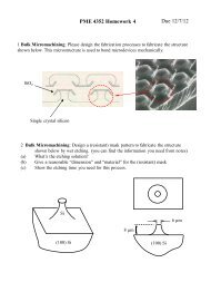
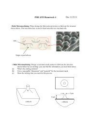
The geometry parameters <str<strong>on</strong>g>of</str<strong>on</strong>g> the <str<strong>on</strong>g>micro</str<strong>on</strong>g> <str<strong>on</strong>g>ball</str<strong>on</strong>g> <str<strong>on</strong>g>lens</str<strong>on</strong>g> and<br />
MEMS structures are indicated in figure 4, where D is the<br />
diameter <str<strong>on</strong>g>of</str<strong>on</strong>g> the <str<strong>on</strong>g>micro</str<strong>on</strong>g> <str<strong>on</strong>g>ball</str<strong>on</strong>g> <str<strong>on</strong>g>lens</str<strong>on</strong>g>, h is the thickness <str<strong>on</strong>g>of</str<strong>on</strong>g> the silic<strong>on</strong><br />
wafer, d is the diameter <str<strong>on</strong>g>of</str<strong>on</strong>g> the circular opening <strong>on</strong> the <str<strong>on</strong>g>lens</str<strong>on</strong>g><br />
frame, t is the U-shape cross secti<strong>on</strong> depth <str<strong>on</strong>g>of</str<strong>on</strong>g> the <str<strong>on</strong>g>lens</str<strong>on</strong>g> frame<br />
Figure 4. (a) Top view, and (b), (c) cross secti<strong>on</strong> views <str<strong>on</strong>g>of</str<strong>on</strong>g> the <str<strong>on</strong>g>micro</str<strong>on</strong>g><br />
<str<strong>on</strong>g>ball</str<strong>on</strong>g> <str<strong>on</strong>g>lens</str<strong>on</strong>g> and its supporting MEMS structures.<br />
(determined by the trench depth in figure 3(a)). According<br />
to the liquid polymer formati<strong>on</strong> technique, the <str<strong>on</strong>g>ball</str<strong>on</strong>g> <str<strong>on</strong>g>lens</str<strong>on</strong>g> can<br />
be properly fabricated and assembled between the frame and<br />
Pyrex glass, despite the <str<strong>on</strong>g>lens</str<strong>on</strong>g> diameter D being larger than the<br />
frame opening d and the frame–glass spacing h–t, as indicated<br />
in figure 4(b). In the case <str<strong>on</strong>g>of</str<strong>on</strong>g> figure 4(c), the spacing between<br />
the two frames is h–2t, which is also smaller than the <str<strong>on</strong>g>lens</str<strong>on</strong>g><br />
diameter. Note that the frame opening needs to be larger than<br />
the outer diameter D tip <str<strong>on</strong>g>of</str<strong>on</strong>g> the dispensing tip, as indicated in<br />
figure 3(d). In applicati<strong>on</strong>, the presented <str<strong>on</strong>g>micro</str<strong>on</strong>g> <str<strong>on</strong>g>ball</str<strong>on</strong>g> <str<strong>on</strong>g>lens</str<strong>on</strong>g> can<br />
be employed to manipulate the light beam incident from both<br />
in-plane and out-<str<strong>on</strong>g>of</str<strong>on</strong>g>-plane directi<strong>on</strong>s <strong>on</strong> the SiOB. For instance,<br />
figure 5(a) shows a typical applicati<strong>on</strong> <str<strong>on</strong>g>of</str<strong>on</strong>g> the <str<strong>on</strong>g>micro</str<strong>on</strong>g> <str<strong>on</strong>g>ball</str<strong>on</strong>g> <str<strong>on</strong>g>lens</str<strong>on</strong>g> for<br />
light c<strong>on</strong>densing in the out-<str<strong>on</strong>g>of</str<strong>on</strong>g>-plane directi<strong>on</strong>. The directi<strong>on</strong><br />
<str<strong>on</strong>g>of</str<strong>on</strong>g> light path as indicated in figure 5(a) is suitable for the case<br />
<str<strong>on</strong>g>of</str<strong>on</strong>g> stacking chips. Moreover, figure 5(b) shows the applicati<strong>on</strong><br />
<str<strong>on</strong>g>of</str<strong>on</strong>g> the <str<strong>on</strong>g>micro</str<strong>on</strong>g> <str<strong>on</strong>g>ball</str<strong>on</strong>g> <str<strong>on</strong>g>lens</str<strong>on</strong>g> for light collimating in the in-plane<br />
directi<strong>on</strong>. The in-plane <strong>optical</strong> axis depicted in figure 5(b) is<br />
beneficial to achieve a SiOB within <strong>on</strong>e chip.<br />
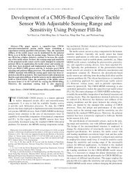
3. Fabricati<strong>on</strong> results<br />
To dem<strong>on</strong>strate the feasibility <str<strong>on</strong>g>of</str<strong>on</strong>g> the presented c<strong>on</strong>cept, the<br />
UV-curable polymer employed in this study was Norland<br />
Optical Adhesive 63 (NOA63) with the refractive index <str<strong>on</strong>g>of</str<strong>on</strong>g><br />
n = 1.56, and specific gravity <str<strong>on</strong>g>of</str<strong>on</strong>g> s = 1.2. Glycerol soluti<strong>on</strong><br />
diluted with distilled water was selected as the immiscible<br />
3
J. Micromech. Microeng. 20 (2010) 085015 C-C Lee et al<br />
(a)<br />
(a)<br />
Dispensing tip<br />
(b)<br />
(b)<br />
Optical fiber<br />
NOA63<br />
(c)<br />
500µm 1mm<br />
(d)<br />
Figure 5. Micro <str<strong>on</strong>g>ball</str<strong>on</strong>g> <str<strong>on</strong>g>lens</str<strong>on</strong>g> <strong>on</strong> SiOB for (a) out-<str<strong>on</strong>g>of</str<strong>on</strong>g>-plane, and<br />
(b) in-plane light c<strong>on</strong>densing/collimating applicati<strong>on</strong>s.<br />
Glass substrate<br />
Si 3N 4<br />
(e) (f )<br />
Optical fiber<br />
buffer liquid. The specific gravity <str<strong>on</strong>g>of</str<strong>on</strong>g> the diluted glycerol<br />
soluti<strong>on</strong> was near s = 1.2. Thus, the immiscible buffer liquid<br />
has almost the same density as the dispensed polymer, and the<br />
influence <str<strong>on</strong>g>of</str<strong>on</strong>g> gravitati<strong>on</strong>al force was ignored. Firstly, in this<br />
study, we dispensed the liquid-phase NOA63 in the diluted<br />
glycerol soluti<strong>on</strong> to form a discrete <str<strong>on</strong>g>ball</str<strong>on</strong>g> <str<strong>on</strong>g>lens</str<strong>on</strong>g>. The photograph<br />
in figure 6(a) shows the polymer dispensing process under<br />
the buffer liquid. The <str<strong>on</strong>g>lens</str<strong>on</strong>g> diameter is properly c<strong>on</strong>trolled by<br />
polymer volume <strong>using</strong> the commercial pneumatic dispensing<br />
system. The dispensing tip indicated in the photograph has an<br />
inner diameter <str<strong>on</strong>g>of</str<strong>on</strong>g> 110 μm and an outer diameter (D tip indicated<br />
in figure 3(d)) <str<strong>on</strong>g>of</str<strong>on</strong>g> D tip = 240 μm. The liquid polymer <str<strong>on</strong>g>lens</str<strong>on</strong>g><br />
was then solidified by the UV light curing process. Further<br />
cleaning and drying steps were applied to complete the <str<strong>on</strong>g>ball</str<strong>on</strong>g><br />
<str<strong>on</strong>g>lens</str<strong>on</strong>g> formati<strong>on</strong> process. The photograph in figure 6(b) shows<br />
typical fabricated <str<strong>on</strong>g>ball</str<strong>on</strong>g> <str<strong>on</strong>g>lens</str<strong>on</strong>g>es with diameters ranging from 200<br />
to 600 μm.<br />
The study further dem<strong>on</strong>strated the integrati<strong>on</strong> <str<strong>on</strong>g>of</str<strong>on</strong>g> the <str<strong>on</strong>g>ball</str<strong>on</strong>g><br />
<str<strong>on</strong>g>lens</str<strong>on</strong>g> with suspended MEMS structures and substrate by means<br />
<str<strong>on</strong>g>of</str<strong>on</strong>g> the processes illustrated in figure 3. The photographs in<br />
figures 6(c) and (d) show a typical fabricated polymer <str<strong>on</strong>g>ball</str<strong>on</strong>g><br />
<str<strong>on</strong>g>lens</str<strong>on</strong>g> and <str<strong>on</strong>g>lens</str<strong>on</strong>g> retainer made <str<strong>on</strong>g>of</str<strong>on</strong>g> thin Si 3 N 4 film. The <str<strong>on</strong>g>ball</str<strong>on</strong>g> <str<strong>on</strong>g>lens</str<strong>on</strong>g><br />
shown in figure 6(c) was implemented <strong>using</strong> the process in<br />
figures 3(a)–(f ). The glassy <str<strong>on</strong>g>micro</str<strong>on</strong>g> <str<strong>on</strong>g>ball</str<strong>on</strong>g> <str<strong>on</strong>g>lens</str<strong>on</strong>g> with a diameter<br />
<str<strong>on</strong>g>of</str<strong>on</strong>g> D = 525 μm is c<strong>on</strong>fined by a transparent glass substrate<br />
and thin Si 3 N 4 frames. The circular opening <str<strong>on</strong>g>of</str<strong>on</strong>g> the Si 3 N 4<br />
retainer in figures 6(c) and (d) has a diameter <str<strong>on</strong>g>of</str<strong>on</strong>g> d = 265 μm<br />
to allow the dispensing tip (D tip = 240 μm) to pass through for<br />
polymer dispensing, as in the process shown in figure 3(d). The<br />
space between the Si 3 N 4 frame and the glass substrate is <strong>on</strong>ly<br />
h − t = 476 μm (
J. Micromech. Microeng. 20 (2010) 085015 C-C Lee et al<br />
(a)<br />
(a)<br />
CCD<br />
Microscope<br />
0 ~360<br />
Light source<br />
45<br />
Computer<br />
(b)<br />
5<br />
Roundness (µm)<br />
4<br />
3<br />
2<br />
1<br />
0<br />
0 60 120 180 240 300 360<br />
Angle (deg)<br />
Figure 7. (a) The experimental setup to measure the roundness <str<strong>on</strong>g>of</str<strong>on</strong>g><br />
the <str<strong>on</strong>g>micro</str<strong>on</strong>g> <str<strong>on</strong>g>ball</str<strong>on</strong>g> <str<strong>on</strong>g>lens</str<strong>on</strong>g>, and (b) the roundness <str<strong>on</strong>g>of</str<strong>on</strong>g> a 550 μm diameter <str<strong>on</strong>g>ball</str<strong>on</strong>g><br />
<str<strong>on</strong>g>lens</str<strong>on</strong>g> observed at different angles.<br />
a 550 μm diameter <str<strong>on</strong>g>ball</str<strong>on</strong>g> <str<strong>on</strong>g>lens</str<strong>on</strong>g> observed from different angles<br />
is about 3.3 ± 0.4 μm [16]. Moreover, the <str<strong>on</strong>g>micro</str<strong>on</strong>g> <str<strong>on</strong>g>lens</str<strong>on</strong>g> has<br />
also been evaluated in terms <str<strong>on</strong>g>of</str<strong>on</strong>g> the radius <str<strong>on</strong>g>of</str<strong>on</strong>g> curvature (ROC),<br />
the RMS surface roughness (Rq), the back focal length (BFL),<br />
the effective focal length (EFL) and the <strong>optical</strong> aberrati<strong>on</strong>. In<br />
this study, the commercial white light interferometer (WYKO)<br />
was employed to characterize the ROC and Rq <str<strong>on</strong>g>of</str<strong>on</strong>g> the polymer<br />
<str<strong>on</strong>g>micro</str<strong>on</strong>g> <str<strong>on</strong>g>ball</str<strong>on</strong>g> <str<strong>on</strong>g>lens</str<strong>on</strong>g>. The typical measured ROC and Rq <str<strong>on</strong>g>of</str<strong>on</strong>g> the<br />
<str<strong>on</strong>g>micro</str<strong>on</strong>g> <str<strong>on</strong>g>lens</str<strong>on</strong>g> are 275 μm and 10 nm, respectively.<br />
This study also established the m<strong>on</strong>ochromatic Mach–<br />
Zehnder interferometer [17–19] as shown in figure 8(a) to<br />
characterize the <strong>optical</strong> aberrati<strong>on</strong> <str<strong>on</strong>g>of</str<strong>on</strong>g> the <str<strong>on</strong>g>micro</str<strong>on</strong>g> <str<strong>on</strong>g>ball</str<strong>on</strong>g> <str<strong>on</strong>g>lens</str<strong>on</strong>g>. As<br />
indicated in figure 8(b), the Mach–Zehnder interferometer<br />
c<strong>on</strong>sists <str<strong>on</strong>g>of</str<strong>on</strong>g> a laser, an <strong>optical</strong> fiber, a polarizer, mirrors, beam<br />
splitters, and a <str<strong>on</strong>g>micro</str<strong>on</strong>g>scope. The 632.8 nm He–Ne laser is<br />
coupled into a single mode fiber (SMF), which acts as a<br />
spatial filter [17, 19]. The polarizati<strong>on</strong> beam splitter (PBS)<br />
is used to split light into a testing beam and a reference beam.<br />
The polarizer (POL) is employed to tune the ratio <str<strong>on</strong>g>of</str<strong>on</strong>g> light<br />
intensity between the testing beam and the reference beam<br />
to improve the c<strong>on</strong>trast <str<strong>on</strong>g>of</str<strong>on</strong>g> the interference fringes. The half<br />
wave plate (HWP) is used to rotate the polarizati<strong>on</strong> <str<strong>on</strong>g>of</str<strong>on</strong>g> the<br />
reference beam by 90 ◦ , and after that, the testing beam and<br />
the reference beam have the same polarizati<strong>on</strong>. In additi<strong>on</strong>,<br />
the phase <str<strong>on</strong>g>of</str<strong>on</strong>g> the reference beam is modulated by the mirror<br />
attached to a piezoelectric actuator (PZT). Meanwhile, a l<strong>on</strong>g<br />
working distance objective (OBJ) with a numerical aperture<br />
<str<strong>on</strong>g>of</str<strong>on</strong>g> NA = 0.55 is exploited to focus the testing beam at the<br />
c<strong>on</strong>focal positi<strong>on</strong> <str<strong>on</strong>g>of</str<strong>on</strong>g> the <str<strong>on</strong>g>micro</str<strong>on</strong>g> <str<strong>on</strong>g>ball</str<strong>on</strong>g> <str<strong>on</strong>g>lens</str<strong>on</strong>g> to be characterized.<br />
(b)<br />
Microscope<br />
NPBS<br />
PZT<br />
Mirror<br />
Micro <str<strong>on</strong>g>lens</str<strong>on</strong>g><br />
OBJ<br />
HWP<br />
POL<br />
Mirror<br />
PBS<br />
SMF<br />
Figure 8. The Mach–Zehnder interferometer setup for waterfr<strong>on</strong>t<br />
aberrati<strong>on</strong> measurement.<br />
He-Ne<br />
Finally, the testing and reference beams are coupled by a n<strong>on</strong>polarizing<br />
beam splitter (NPBS), and then the interferogram<br />
is captured by the <str<strong>on</strong>g>micro</str<strong>on</strong>g>scope. The wavefr<strong>on</strong>t measured<br />
by the Mach–Zehnder interferometer is shown in figure 9<br />
where the peak-to-valley wavefr<strong>on</strong>t aberrati<strong>on</strong> is 0.3744 waves<br />
(237 nm), and the RMS wavefr<strong>on</strong>t aberrati<strong>on</strong> is 0.0766 waves<br />
(48 nm) [18].<br />
Moreover, figure 10 shows the approach to determine the<br />
BFL <str<strong>on</strong>g>of</str<strong>on</strong>g> the <str<strong>on</strong>g>micro</str<strong>on</strong>g> <str<strong>on</strong>g>lens</str<strong>on</strong>g>. Firstly, the <str<strong>on</strong>g>micro</str<strong>on</strong>g>scope is focused <strong>on</strong><br />
the surface <str<strong>on</strong>g>of</str<strong>on</strong>g> the <str<strong>on</strong>g>micro</str<strong>on</strong>g> <str<strong>on</strong>g>ball</str<strong>on</strong>g> <str<strong>on</strong>g>lens</str<strong>on</strong>g>, as shown in figure 10(a).<br />
After that, the <str<strong>on</strong>g>micro</str<strong>on</strong>g> <str<strong>on</strong>g>ball</str<strong>on</strong>g> <str<strong>on</strong>g>lens</str<strong>on</strong>g> is moved until the minimum light<br />
spot <str<strong>on</strong>g>of</str<strong>on</strong>g> the incident He–Ne laser illuminating is observed, as<br />
shown in figure 10(b). Thus, the BFL is determined from<br />
the moving distance <str<strong>on</strong>g>of</str<strong>on</strong>g> the <str<strong>on</strong>g>micro</str<strong>on</strong>g> <str<strong>on</strong>g>lens</str<strong>on</strong>g>. In this study, the<br />
measured BFL was about 99 μm, and the associated EFL was<br />
about 351 μm. These measurement results show the <str<strong>on</strong>g>micro</str<strong>on</strong>g><br />
<str<strong>on</strong>g>ball</str<strong>on</strong>g> <str<strong>on</strong>g>lens</str<strong>on</strong>g>es fabricated by the presented insoluble two-phase<br />
liquid immersi<strong>on</strong> technology have the same quality as other<br />
<str<strong>on</strong>g>micro</str<strong>on</strong>g> <str<strong>on</strong>g>lens</str<strong>on</strong>g>es formed <strong>on</strong> a planar substrate under air ambient<br />
c<strong>on</strong>diti<strong>on</strong>s [20]. To verify the repeatability <str<strong>on</strong>g>of</str<strong>on</strong>g> <str<strong>on</strong>g>lens</str<strong>on</strong>g> formati<strong>on</strong>,<br />
in this study, we dispensed and characterized <str<strong>on</strong>g>micro</str<strong>on</strong>g> <str<strong>on</strong>g>ball</str<strong>on</strong>g> <str<strong>on</strong>g>lens</str<strong>on</strong>g>es<br />
with diameters ranging from 270 to 500 μm, and 20 samples<br />
5
J. Micromech. Microeng. 20 (2010) 085015 C-C Lee et al<br />
Wavefr<strong>on</strong>t error<br />
(waves)<br />
0.1<br />
0.0<br />
-0.1<br />
-0.2<br />
250<br />
Wavefr<strong>on</strong>t error<br />
(waves)<br />
0.1<br />
0.0<br />
-0.1<br />
-0.2<br />
BFL(µm)<br />
90<br />
80<br />
70<br />
60<br />
50<br />
200<br />
40<br />
Y(µm)<br />
150<br />
100<br />
50<br />
30<br />
250 300 350 400 450 500<br />
Diameter(µm)<br />
Figure 11. The measured distributi<strong>on</strong> <str<strong>on</strong>g>of</str<strong>on</strong>g> the <str<strong>on</strong>g>lens</str<strong>on</strong>g> diameter and the<br />
BFL for each size <str<strong>on</strong>g>of</str<strong>on</strong>g> <str<strong>on</strong>g>micro</str<strong>on</strong>g> <str<strong>on</strong>g>ball</str<strong>on</strong>g> <str<strong>on</strong>g>lens</str<strong>on</strong>g>.<br />
0<br />
0 50 100 150 200 250<br />
X(µm)<br />
Figure 9. The wavefr<strong>on</strong>t error <str<strong>on</strong>g>of</str<strong>on</strong>g> a 275 μm ROC <str<strong>on</strong>g>micro</str<strong>on</strong>g> <str<strong>on</strong>g>ball</str<strong>on</strong>g> <str<strong>on</strong>g>lens</str<strong>on</strong>g>.<br />
The tilt and power <str<strong>on</strong>g>of</str<strong>on</strong>g> the aberrati<strong>on</strong> are removed.<br />
(a)<br />
Refractive index<br />
1.59<br />
1.58<br />
1.57<br />
1.56<br />
1.55<br />
1.54<br />
NOA63 cured in air<br />
NOA63 cured in glycerol<br />
1.53<br />
400 500 600 700 800<br />
Wavelength (nm)<br />
Figure 12. The refractive indices <str<strong>on</strong>g>of</str<strong>on</strong>g> the NOA63 polymer cured in<br />
air and glycerol, respectively.<br />
(b)<br />
Microscope<br />
BFL<br />
Figure 10. The experimental setup to measure the BFL <str<strong>on</strong>g>of</str<strong>on</strong>g> <str<strong>on</strong>g>micro</str<strong>on</strong>g><br />
<str<strong>on</strong>g>ball</str<strong>on</strong>g> <str<strong>on</strong>g>lens</str<strong>on</strong>g>.<br />
were measured for each size <str<strong>on</strong>g>of</str<strong>on</strong>g> <str<strong>on</strong>g>lens</str<strong>on</strong>g>. The measurements in<br />
figure 11 show the distributi<strong>on</strong> <str<strong>on</strong>g>of</str<strong>on</strong>g> the <str<strong>on</strong>g>lens</str<strong>on</strong>g> diameter and the<br />
BFL for each size <str<strong>on</strong>g>of</str<strong>on</strong>g> <str<strong>on</strong>g>micro</str<strong>on</strong>g> <str<strong>on</strong>g>ball</str<strong>on</strong>g> <str<strong>on</strong>g>lens</str<strong>on</strong>g>. It can be seen that the<br />
presented two-phase liquid <str<strong>on</strong>g>micro</str<strong>on</strong>g> <str<strong>on</strong>g>ball</str<strong>on</strong>g> <str<strong>on</strong>g>lens</str<strong>on</strong>g> formati<strong>on</strong> method<br />
has a reas<strong>on</strong>able repeatability. Moreover, the refractive indices<br />
<str<strong>on</strong>g>of</str<strong>on</strong>g> the NOA63 polymer cured in both air and glycerol were<br />
measured. The measurement results, as shown in figure 12,<br />
indicate that the refractive index difference is about 0.5%.<br />
5. C<strong>on</strong>clusi<strong>on</strong>s<br />
This study presents a <str<strong>on</strong>g>ball</str<strong>on</strong>g> <str<strong>on</strong>g>lens</str<strong>on</strong>g> formati<strong>on</strong> and integrati<strong>on</strong><br />
technology utilizing the two-phase liquid approach. The UV-<br />
curable polymer is dispensed into a buffer liquid to form the<br />
<str<strong>on</strong>g>ball</str<strong>on</strong>g> <str<strong>on</strong>g>lens</str<strong>on</strong>g>. Thus, the buffer liquid can provide a gravity-free<br />
c<strong>on</strong>diti<strong>on</strong> to enable the <str<strong>on</strong>g>ball</str<strong>on</strong>g> <str<strong>on</strong>g>lens</str<strong>on</strong>g> with a highly symmetric shape.<br />
The diameter <str<strong>on</strong>g>of</str<strong>on</strong>g> the <str<strong>on</strong>g>ball</str<strong>on</strong>g> <str<strong>on</strong>g>lens</str<strong>on</strong>g> is c<strong>on</strong>trolled by the volume<br />
<str<strong>on</strong>g>of</str<strong>on</strong>g> the dispensed polymer. In applicati<strong>on</strong>, the formati<strong>on</strong> <str<strong>on</strong>g>of</str<strong>on</strong>g><br />
the NOA63 polymer <str<strong>on</strong>g>ball</str<strong>on</strong>g> <str<strong>on</strong>g>lens</str<strong>on</strong>g> in glycerol buffer liquid is<br />
dem<strong>on</strong>strated. The typical <str<strong>on</strong>g>ball</str<strong>on</strong>g> <str<strong>on</strong>g>lens</str<strong>on</strong>g> diameter ranges from<br />
200 to 600 μm, and its surface roughness measured by an<br />
<strong>optical</strong> interferometer is about 10 nm. The average roundness<br />
<str<strong>on</strong>g>of</str<strong>on</strong>g> a 550 μm diameter <str<strong>on</strong>g>ball</str<strong>on</strong>g> <str<strong>on</strong>g>lens</str<strong>on</strong>g> measured from different angles<br />
is 3.3 ± 0.4 μm. According to the measurement results <str<strong>on</strong>g>of</str<strong>on</strong>g><br />
a Mach–Zehnder interferometer, the peak-to-valley and RMS<br />
wavefr<strong>on</strong>t errors <str<strong>on</strong>g>of</str<strong>on</strong>g> a 550 μm diameter <str<strong>on</strong>g>ball</str<strong>on</strong>g> <str<strong>on</strong>g>lens</str<strong>on</strong>g> are 237 nm and<br />
48 nm, respectively. The measured BFL is about 99 μm, and<br />
the associated EFL is about 351 μm. The presented approach<br />
can be further employed to implement polymer <str<strong>on</strong>g>ball</str<strong>on</strong>g> <str<strong>on</strong>g>lens</str<strong>on</strong>g>es <str<strong>on</strong>g>of</str<strong>on</strong>g><br />
different materials. Moreover, the integrati<strong>on</strong> <str<strong>on</strong>g>of</str<strong>on</strong>g> the <str<strong>on</strong>g>micro</str<strong>on</strong>g> <str<strong>on</strong>g>ball</str<strong>on</strong>g><br />
<str<strong>on</strong>g>lens</str<strong>on</strong>g> with a suspended <str<strong>on</strong>g>micro</str<strong>on</strong>g>machined thin Si 3 N 4 structure is<br />
also dem<strong>on</strong>strated.<br />
Acknowledgments<br />
This work was supported partially by the Ministry <str<strong>on</strong>g>of</str<strong>on</strong>g> Ec<strong>on</strong>omic<br />
Affairs, Taiwan, under c<strong>on</strong>tract number 97-EC-17-A-07-S1-<br />
011, and by the Nati<strong>on</strong>al Science Council, Taiwan, under<br />
c<strong>on</strong>tract number NSC-96-2628-E-007-008-MY3.<br />
6
J. Micromech. Microeng. 20 (2010) 085015 C-C Lee et al<br />
References<br />
[1] Walker J A 2000 The future <str<strong>on</strong>g>of</str<strong>on</strong>g> MEMS in telecommunicati<strong>on</strong>s<br />
networks J. Micromech. Microeng. 10 R1–7<br />
[2] Schwarz R A, Arifler D, Chang S K, Pavlova I, Hussain I A,<br />
Mack V, Knight B, Richards-Kortum R and Gillenwater A<br />
M 2005 Ball <str<strong>on</strong>g>lens</str<strong>on</strong>g> coupled fiber-optic probe for<br />
depth-resolved spectroscopy <str<strong>on</strong>g>of</str<strong>on</strong>g> epithelial tissue Opt. Lett.<br />
30 1159–61<br />
[3] Jiang W, Sun Y, Chen R T, Guo B, Horwitz J and Morey W<br />
2002 Ball-<str<strong>on</strong>g>lens</str<strong>on</strong>g> based <strong>optical</strong> add-drop multiplexers: design<br />
and implementati<strong>on</strong> IEEE Phot<strong>on</strong>ics Technol. Lett.<br />
14 825–7<br />
[4] Sasaki M, Nakai F, Hane K, Yokomizo K and Hori K 2006<br />
Absolute <str<strong>on</strong>g>micro</str<strong>on</strong>g>-encoder <strong>using</strong> image obtained by <str<strong>on</strong>g>ball</str<strong>on</strong>g> <str<strong>on</strong>g>lens</str<strong>on</strong>g><br />
assembled inside wafer J. Opt. A: Pure Appl. Opt. 8 S391–7<br />
[5] Huby N, Pluch<strong>on</strong> D, Coul<strong>on</strong> N, Belloul M, Moreac A,<br />
Gaviot E, Panizza P and Beche B 2010 Design <str<strong>on</strong>g>of</str<strong>on</strong>g> organic<br />
3D <str<strong>on</strong>g>micro</str<strong>on</strong>g>res<strong>on</strong>ators with micr<str<strong>on</strong>g>of</str<strong>on</strong>g>luidics coupled to thin-film<br />
processes for phot<strong>on</strong>ic applicati<strong>on</strong>s Opt. Commun.<br />
283 2451–6<br />
[6] Kim Y S, Kim J, Choe J S, Rob Y G, Je<strong>on</strong> H and Woo J C<br />
2000 Semic<strong>on</strong>ductor <str<strong>on</strong>g>micro</str<strong>on</strong>g><str<strong>on</strong>g>lens</str<strong>on</strong>g>es fabricated by <strong>on</strong>e-step<br />
wet etching IEEE Phot<strong>on</strong>ics Technol. Lett. 12 507–9<br />
[7] O’Neill F T and Sheridan J T 2002 Photoresist reflow method<br />
<str<strong>on</strong>g>of</str<strong>on</strong>g> <str<strong>on</strong>g>micro</str<strong>on</strong>g><str<strong>on</strong>g>lens</str<strong>on</strong>g> producti<strong>on</strong>: part I. Background and<br />
experiments Optik—Int. J. Light Electr<strong>on</strong> Opt. 113 391–404<br />
[8] Lee S-K, Lee K-C and Lee S S 2002 A simple method for<br />
<str<strong>on</strong>g>micro</str<strong>on</strong>g><str<strong>on</strong>g>lens</str<strong>on</strong>g> fabricati<strong>on</strong> by the modified LIGA process<br />
J. Micromech. Microeng. 12 334–40<br />
[9] Audran S, Faure B, Mortini B, Regolini J, Schlatter G<br />
and Hadziioannou G 2006 Study <str<strong>on</strong>g>of</str<strong>on</strong>g> mechanisms involved in<br />
photoresist <str<strong>on</strong>g>micro</str<strong>on</strong>g><str<strong>on</strong>g>lens</str<strong>on</strong>g> formati<strong>on</strong> Microelectr<strong>on</strong>. Eng.<br />
83 1087–90<br />
[10] Cox W R, Chen T, Hayes D J and Grove M E 2001 Microjet<br />
printing <str<strong>on</strong>g>of</str<strong>on</strong>g> <str<strong>on</strong>g>micro</str<strong>on</strong>g>-<strong>optical</strong> interc<strong>on</strong>nects for telecom devices<br />
Proc. SPIE 4292 208<br />
[11] Shen S C and Huang J C 2009 Rapid fabricati<strong>on</strong> <str<strong>on</strong>g>of</str<strong>on</strong>g> a<br />
<str<strong>on</strong>g>micro</str<strong>on</strong>g>-<str<strong>on</strong>g>ball</str<strong>on</strong>g> <str<strong>on</strong>g>lens</str<strong>on</strong>g> array by extrusi<strong>on</strong> for <strong>optical</strong> fiber<br />
applicati<strong>on</strong>s Opt. Express 17 13122–7<br />
[12] Hsieh J, Hsiao S-Y, Lai C F and Fang W 2007 Integrati<strong>on</strong> <str<strong>on</strong>g>of</str<strong>on</strong>g> a<br />
UV curable polymer <str<strong>on</strong>g>lens</str<strong>on</strong>g> and MUMPs structures <strong>on</strong> a SOI<br />
<strong>optical</strong> <strong>bench</strong> J. Micromech. Microeng. 17 1703–9<br />
[13] Lee C-C, Hsiao S-Y and Fang W 2009 Formati<strong>on</strong> and<br />
Integrati<strong>on</strong> <str<strong>on</strong>g>of</str<strong>on</strong>g> a <str<strong>on</strong>g>ball</str<strong>on</strong>g> <str<strong>on</strong>g>lens</str<strong>on</strong>g> utilizing two phase liquid<br />
technology Proc. IEEE MEMS (Sorrento, Italy) pp 172–5<br />
[14] Han M-G, Park Y-J, Kim S-H, Yoo B-S and Park H-H 2004<br />
Thermal and chemical stability <str<strong>on</strong>g>of</str<strong>on</strong>g> reflowed-photoresist<br />
<str<strong>on</strong>g>micro</str<strong>on</strong>g><str<strong>on</strong>g>lens</str<strong>on</strong>g>es J. Micromech. Microeng. 14 398–402<br />
[15] Lin H-Y and Fang W 2000 Rib-reinforced <str<strong>on</strong>g>micro</str<strong>on</strong>g>machined<br />
beam and its applicati<strong>on</strong>s J. Micromech. Microeng. 10 93–9<br />
[16] Smith G T 2002 Industrial Metrology: Surfaces and<br />
Roundness (L<strong>on</strong>d<strong>on</strong>: Springer)<br />
[17] Sickinger H, Schwider J and Manzke B 1999 Fiber based<br />
Mach–Zehnder interferometer for measuring wave<br />
aberrati<strong>on</strong>s <str<strong>on</strong>g>of</str<strong>on</strong>g> <str<strong>on</strong>g>micro</str<strong>on</strong>g><str<strong>on</strong>g>lens</str<strong>on</strong>g>es Optik 110 239–43<br />
[18] Reichelt S, Bieber A, Aatz B and Zappe H2005 Micro-optics<br />
metrology <strong>using</strong> advanced interferometry Proc. SPIE 5856<br />
pp 437–46<br />
[19] Gomez V, Ghim T-S, Ottevaere H, Gardner N, Bergner B,<br />
Medicus K, Davies A and Thienp<strong>on</strong>t H 2009 Micro-optic<br />
reflecti<strong>on</strong> and transmissi<strong>on</strong> interferometer for complete<br />
<str<strong>on</strong>g>micro</str<strong>on</strong>g><str<strong>on</strong>g>lens</str<strong>on</strong>g> characterizati<strong>on</strong> Meas. Sci. Technol. 20 025901<br />
[20] Ottevaere H, Cox R, Herzig H P, Miyashita T, Naessens K,<br />
Taghizadeh M, Volkel R, Woo H J and Thienp<strong>on</strong>t H 2006<br />
Comparing glass and plastic refractive <str<strong>on</strong>g>micro</str<strong>on</strong>g><str<strong>on</strong>g>lens</str<strong>on</strong>g>es<br />
fabricated with different technologies J. Opt. A: Pure Appl.<br />
Opt. 8 S407–29<br />
7