Aust Workshops - TUFLOW Modelling Bends, Structures and ...
Aust Workshops - TUFLOW Modelling Bends, Structures and ...
Aust Workshops - TUFLOW Modelling Bends, Structures and ...

Create successful ePaper yourself
Turn your PDF publications into a flip-book with our unique Google optimized e-Paper software.
<strong>Aust</strong>ralian 2011/2012 <strong>TUFLOW</strong> <strong>Workshops</strong><br />
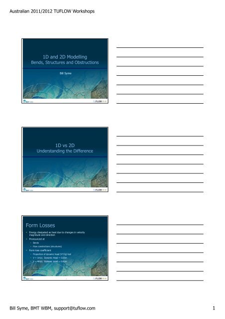
1D <strong>and</strong> 2D <strong>Modelling</strong><br />
<strong>Bends</strong>, <strong>Structures</strong> <strong>and</strong> Obstructions<br />
Bill Syme<br />
1D vs 2D<br />
Underst<strong>and</strong>ing the Difference<br />
Form Losses<br />
• Energy dissipated as heat due to changes in velocity<br />
magnitude <strong>and</strong> direction<br />
• Pronounced at<br />
• <strong>Bends</strong><br />
• Flow constrictions (structures)<br />
• Form loss coefficient<br />
• Proportion of dynamic head (V 2 /2g) lost<br />
• V = 1m/s; Dynamic Head = 0.05m<br />
• V = 4m/s; Dynamic Head = 0.82m<br />
3<br />
Bill Syme, BMT WBM, support@tuflow.com<br />
1
<strong>Aust</strong>ralian 2011/2012 <strong>TUFLOW</strong> <strong>Workshops</strong><br />
Right-Angled Bend<br />
1D vs 2D<br />
4<br />
<br />
3<br />
3<br />
<br />
1<br />
<br />
<br />
<br />
1 2 2<br />
A<br />
0.5<br />
Water Surface Profiles (V = 2m/s)<br />
0.4<br />
Coarse 2D Model<br />
1D Model<br />
1D Model<br />
Water Level (m)<br />
0.3<br />
0.2<br />
0.1<br />
A<br />
0<br />
-0.1<br />
0 50 100 150 200 250 300 350 400 450<br />
Distance (m)<br />
4<br />
River<br />
<strong>Bends</strong><br />
23.2<br />
23.4<br />
23.2 23.2 23.2 23.2 23.2 23.2 23.2 23.2 23.2<br />
23.4 23.4 23.4 23.4 23.4 23.4 23.4 23.4 23.4<br />
23.6 23.6 23.6 23.6 23.6 23.6 23.6 23.6 23.6<br />
23.4 23.4 23.4 23.4 23.4 23.4 23.4 23.4<br />
23.2 23.2 23.2 23.2 23.2 23.2 23.2 23.2 23.2<br />
3<br />
• 4 m/s<br />
• 20 m deep<br />
23.6 23.6<br />
23.6<br />
• 0.4m<br />
superelevation<br />
23.8 23.8 23.8 23.8 23.8 23.8 23.8 23.8 23.8<br />
24 24 24 24 24 24 24 24 24<br />
• 1D:<br />
• Need additional<br />
losses<br />
(eg. higher n)<br />
• No superelevation<br />
24.4 24.4 24.4 24.4 24.4 24.4 24.4 24.4 24.4<br />
24.2<br />
23.8 23.8 23.8 23.8 23.8 23.8 23.8 23.8 23.8<br />
24<br />
23.8<br />
23.6 23.6 23.6 23.6 23.6 23.6 23.6 23.6 23.6<br />
23.4 23.4 23.4 23.4 23.4 23.4 23.4 23.4 23.4<br />
23 23 23 23 23 23 23 23 23<br />
23.2 23.2 23.2 23.2 23.2 23.2 23.2 23.2 23.2<br />
22.8 22.8 22.8 22.8 22.8 22.8 22.8 22.8 22.8<br />
22.6 22.6 22.6 22.6 22.6 22.6 22.6 22.6 22.6<br />
22<br />
4<br />
5<br />
2D vs 3D?<br />
2D<br />
3D<br />
23 cm 30 cm<br />
6<br />
6<br />
Bill Syme, BMT WBM, support@tuflow.com<br />
2
<strong>Aust</strong>ralian 2011/2012 <strong>TUFLOW</strong> <strong>Workshops</strong><br />
<strong>Bends</strong> - Conclusions<br />
1D <strong>and</strong> 2D Approaches<br />
• 1D<br />
• 2D<br />
• Apply extra losses by<br />
• Form loss coefficient, or<br />
• Increasing Manning’s n<br />
• Do not model superelevation<br />
• Form losses inherent / Models superelevation<br />
• However<br />
• Are model elements too coarse to simulate all losses?<br />
• Are there losses in the vertical plane? (Helicoidal circulations)<br />
• Additional form losses may be required<br />
7<br />
Hydraulic <strong>Structures</strong><br />
• Hydraulic <strong>Structures</strong><br />
• Bridges <strong>and</strong> Embankments<br />
• Large Culverts<br />
• Hydraulics is Complex (3D)<br />
• 1D: Traditional Approach<br />
• 2D: Looks impressive, but is it accurate?<br />
• 1D/2D: Best of both?<br />
8<br />
2D: Looks impressive, but is it accurate?<br />
?<br />
9<br />
Bill Syme, BMT WBM, support@tuflow.com<br />
3
<strong>Aust</strong>ralian 2011/2012 <strong>TUFLOW</strong> <strong>Workshops</strong><br />
1D: Traditional Approach<br />
Uses Contraction/Expansion Losses<br />
10<br />
1D Culvert Entrance <strong>and</strong><br />
Exit Loss Coefficients<br />
• Coefficients adjusted according to approach <strong>and</strong> departure velocities in a 1D<br />
network (n/a yet when connected to 2D)<br />
• Can fix losses (ie. no adjustment) if desired<br />
• Default unadjusted values typically 0.5 <strong>and</strong> 1.0<br />
• Energy loss is C*V s2 /2g<br />
V<br />
Centrance<br />
_ adjusted = Centrance<br />
<br />
1 <br />
V<br />
V <br />
_ 1 <br />
departure<br />
Cexit<br />
adjusted = Cexit<br />
<br />
Vstructure<br />
<br />
approach<br />
structure<br />
2<br />
<br />
<br />
<br />
11<br />
2D: No Contraction/Expansion Losses?<br />
12<br />
Bill Syme, BMT WBM, support@tuflow.com<br />
4
<strong>Aust</strong>ralian 2011/2012 <strong>TUFLOW</strong> <strong>Workshops</strong><br />
2D Scheme Modifications<br />
(2d_fc or 2d_fcsh layers)<br />
Cell Obvert<br />
Partially block cell sides<br />
Deck FLC<br />
Form Loss<br />
Coefficient<br />
13<br />
2D Layered Adjustments<br />
(2d_lfcsh layers)<br />
Blockage = 0%<br />
FLC = 0<br />
Blockage = 50%<br />
FLC = 0.5<br />
Blockage = 100%<br />
FLC = 0.8<br />
Blockage = 5%<br />
Form Loss Coeff = 0.1<br />
14<br />
2.88 m 1<br />
1<br />
2 2 3 <br />
3<br />
2.30 m<br />
4<br />
0.7 m/s<br />
2.86 m<br />
2.42 m<br />
2.9 m/s<br />
0.8 m/s<br />
3<br />
Water Surface Profiles - Outlet Controlled<br />
2.9<br />
2.8<br />
1D Model<br />
Water Level (m)<br />
2.7<br />
2.6<br />
2.5<br />
Upstream<br />
of Culvert<br />
Downstream<br />
of Culvert<br />
2.4<br />
2.3<br />
2.2<br />
0 50 100 150 200 250 300<br />
Distance (m)<br />
15<br />
Bill Syme, BMT WBM, support@tuflow.com<br />
5
<strong>Aust</strong>ralian 2011/2012 <strong>TUFLOW</strong> <strong>Workshops</strong><br />
<br />
Modify 2D Cells<br />
to represent<br />
culvert<br />
Water Surface Profiles - Outlet Controlled<br />
3<br />
2.9<br />
1D Model<br />
2.8<br />
2D Model (Culvert as 2D Cells)<br />
Water Level (m)<br />
2.7<br />
2.6<br />
2.5<br />
Upstream<br />
of Culvert<br />
Downstream<br />
of Culvert<br />
2.4<br />
2.3<br />
2.2<br />
0 50 100 150 200 250 300<br />
Distance (m)<br />
16<br />
So 2D isn’t perfect!<br />
What are our options?<br />
• Don’t use 2D!<br />
• Adapt 2D Solution<br />
• Insert 1D Solution<br />
17<br />
“Calibrating”<br />
2D <strong>Structures</strong><br />
• For example,<br />
if we apply a<br />
0.2 FLC,<br />
ie. add<br />
0.2*V 2 /2g<br />
energy loss<br />
<br />
Water Level (m)<br />
3<br />
2.9<br />
2.8<br />
2.7<br />
2.6<br />
2.5<br />
2.4<br />
2.3<br />
2.2<br />
Water Surface Water Profiles Surface - Outlet Profiles Controlled - Outlet - Controlled Adjusted Form Losses<br />
Upstream<br />
of Culvert<br />
Downstream<br />
of Culvert<br />
0 50 100 150 200 250 300<br />
Distance (m)<br />
1D 1D Model<br />
2D 2D Model (Culvert as as 2D 2D Cells)<br />
Bill Syme, BMT WBM, support@tuflow.com<br />
6
<strong>Aust</strong>ralian 2011/2012 <strong>TUFLOW</strong> <strong>Workshops</strong><br />
1D/2D<br />
Link<br />
Options<br />
2.88 m 1 <br />
1<br />
0.7 m/s<br />
2.86 m<br />
2.42 Modify m<br />
Block 2D Cells<br />
2 2 3 to <strong>and</strong> represent insert<br />
3<br />
2.9 m/s<br />
0.8 m/s<br />
culvert 1D element<br />
2.30 m<br />
4<br />
• SX Link<br />
• HX Link<br />
(Preserves<br />
momentum)<br />
Water Level (m)<br />
(m)<br />
3<br />
2.9<br />
2.9<br />
2.8<br />
2.8<br />
2.7<br />
2.7<br />
2.6<br />
2.6<br />
2.5<br />
2.5<br />
2.4<br />
2.4<br />
2.3<br />
2.3<br />
Water Surface Profiles - - Outlet Controlled<br />
1D 1D<br />
Model<br />
Model<br />
2D 2D Model Model (Culvert<br />
1D Model as as 2D 2D Cells)<br />
2D Model (Culvert as 1D Element)<br />
2D 2D Model Model (Culvert (Culvert as 1D as Element) 2D Cells)<br />
2D (1D Culvert & Momentum)<br />
Upstream<br />
Downstream<br />
Upstream Downstream<br />
of Culvert<br />
of of Culvert<br />
of Culvert of Culvert<br />
2.2<br />
2.2<br />
0 50 100 150 200 250 300<br />
0 50 100 150 200 250 300<br />
Distance (m)<br />
Distance (m)<br />
19<br />
“Calibrating”<br />
1D Culvert<br />
linked to 2D<br />
<br />
<br />
<br />
• Culvert as 1D<br />
Element<br />
• Reduce Outlet<br />
Loss<br />
Coefficient by<br />
0.2<br />
Water Level (m)<br />
Water Surface Profiles - Outlet Controlled - Adjusted Form Losses<br />
3<br />
1D Model<br />
2.9<br />
1D Model<br />
2D Model (Culvert 1D Model as 2D Cells)<br />
2.8<br />
2D Model (Culvert as 2D Cells)<br />
2D Model (Culvert as 1D Element)<br />
2.7<br />
2.6<br />
Upstream<br />
Downstream<br />
of Culvert<br />
of Culvert<br />
2.5<br />
2.4<br />
2.3<br />
2.2<br />
0 50 100 150 200 250 300<br />
Distance (m)<br />
20<br />
<strong>Modelling</strong> Culverts - Conclusions<br />
• Culvert as 2D Cell(s)<br />
• 2D solution models 70 to 80% of losses<br />
• Need 20 to 30% additional form losses<br />
• Culvert as 1D Element<br />
• Over predicts losses by 0 to 70%<br />
• Small – 0% over prediction<br />
• Large – up to 70% over prediction<br />
• Reduce inlet / outlet losses of 1D element(s)<br />
21 21<br />
Bill Syme, BMT WBM, support@tuflow.com<br />
7
<strong>Aust</strong>ralian 2011/2012 <strong>TUFLOW</strong> <strong>Workshops</strong><br />
Embankments / Levees<br />
(Weir Flow)<br />
• Approach<br />
• Test submergence<br />
across cell side<br />
• BC Weir equation if<br />
unsubmerged<br />
• No adjustment if<br />
submerged<br />
<br />
2.4<br />
2.2<br />
2<br />
Cell sides set to 1m high<br />
for 2D Model (Thin Weir)<br />
Comparison Upstream Water Level Hydrographs<br />
Unsubmerged<br />
Submerged<br />
400<br />
350<br />
300<br />
• Thin Weir Test<br />
Water Level (m)<br />
1.8<br />
1.6<br />
1.4<br />
1D<br />
1D<br />
Model<br />
Model<br />
& Theory<br />
Theory<br />
D/S Water Level<br />
2D Model (Thin Weir)<br />
D/S Water Level<br />
D/S Water Level<br />
Inflow Hydrograph<br />
Inflow<br />
Inflow<br />
Hydrograph<br />
Hydrograph<br />
250<br />
200<br />
150<br />
Inflow (m 3 /s)<br />
1.2<br />
100<br />
1<br />
Weir Crest Level<br />
50<br />
0.8<br />
0<br />
0:00 0:30 1:00 1:30 2:00 2:30 3:00 3:30<br />
Time (hh:mm)<br />
22<br />
Oblique Weirs<br />
• Flow oblique to<br />
grid<br />
• Weir at 45˚ test Unit Flow Across a Broad-Crested Weir - Upstream Controlled<br />
3.50<br />
• Correct using weir<br />
coefficient<br />
Unit Flow (m 2 /s)<br />
3.00<br />
2.50<br />
2.00<br />
1.50<br />
1.00<br />
BC Weir Formula<br />
BC Weir Formula<br />
2D Model BC (Weir Formula Coef = 1.0)<br />
2D Model (Weir Coef 1.0)<br />
2D Model (Weir Coef = 1.1)<br />
0.50<br />
0.00<br />
0 0.2 0.4 0.6 0.8 1 1.2 1.4 1.6<br />
Upstream Head above Sill (m)<br />
23<br />
Conclusions<br />
• 2D contracts <strong>and</strong> exp<strong>and</strong>s flow lines<br />
• Inherently models form losses<br />
• May not model 100% of losses<br />
• Need ability to add form losses (calibrate)<br />
• Need momentum <strong>and</strong> viscosity terms<br />
• Linking 1D structures into 2D<br />
• Useful when the structure is small<br />
• Large structures (relative to 2D cell size) may over predict losses<br />
• May need to reduce inlet / outlet losses (calibrate)<br />
• Check <strong>and</strong> UNDERSTAND your results<br />
24 24<br />
Bill Syme, BMT WBM, support@tuflow.com<br />
8
<strong>Aust</strong>ralian 2011/2012 <strong>TUFLOW</strong> <strong>Workshops</strong><br />
1D/2D Linking<br />
1D/2D Interface Linking<br />
1D Carved Through 2D<br />
• Define 1D/2D Interface<br />
(digitise along the top or crest of the bank)<br />
• Connect 1D nodes to<br />
1D/2D interface<br />
(digitise perpendicular to flow)<br />
10.0<br />
10.2<br />
10.1<br />
26 26<br />
1D/2D Interface Linking<br />
1D Carved Through 2D<br />
• If levee, digitise HX<br />
line along<br />
levee crest<br />
HX<br />
Thick Z Line needed<br />
HX<br />
• Use a Thick Z Line to<br />
ensure HX cell is set<br />
to levee crest height<br />
<strong>and</strong> overtopping<br />
occurs at correct<br />
height<br />
27 27<br />
Bill Syme, BMT WBM, support@tuflow.com<br />
9
<strong>Aust</strong>ralian 2011/2012 <strong>TUFLOW</strong> <strong>Workshops</strong><br />
1D/2D Interface Linking<br />
1D Carved Through 2D<br />
• Cross-sections must extend from<br />
HX line to HX line<br />
(ToB to ToB)<br />
• Use a Thick Z Line along<br />
HX lines to set ToB<br />
levels at HX cells<br />
28 28<br />
1D/2D Interface Troubleshooting<br />
• Ensure Cell elevations are representative of spill levels<br />
–use a Thick Z Line<br />
• Most common cause by far is bumpy HX cell elevations<br />
• Poor 1D resolution<br />
• Missing connections<br />
• Add additional FLC (energy loss) works well<br />
(2010 version can be added directly to HX line using “a” attribute)<br />
29<br />
29<br />
1D/2D Structure Linking<br />
Culvert Through an Embankment<br />
• 2D water levels define<br />
water level gradient<br />
across culvert<br />
• Flow through culvert<br />
applied as a sink/source<br />
to 2D cells<br />
• Make sure width of 2D SX<br />
cells EXCEEDS width of<br />
1D flow (at all elevations)<br />
30 30<br />
Bill Syme, BMT WBM, support@tuflow.com<br />
10
<strong>Aust</strong>ralian 2011/2012 <strong>TUFLOW</strong> <strong>Workshops</strong><br />
1D/2D Pipe Network Linking<br />
Underground Pipe Network<br />
• Use pits to connect<br />
pipe network with<br />
overl<strong>and</strong> 2D<br />
• 2D water level at<br />
cell drives 1D pipe<br />
hydraulics<br />
(unless pit is not full)<br />
• Net pipe flow in/out<br />
of pit applied as<br />
sink/source to 2D<br />
cell<br />
31 31<br />
<strong>Modelling</strong> Urban Areas<br />
Culvert Flow<br />
Inlet Control Regimes<br />
HW<br />
HW<br />
TW<br />
TW<br />
A: Unsubmerged Entrance,<br />
Supercritical Slope<br />
B: Submerged Entrance,<br />
Supercritical Slope<br />
HW<br />
TW<br />
HW<br />
TW<br />
K: Unsubmerged Entrance,<br />
Submerged Exit<br />
Critical at Entrance<br />
L: Submerged Entrance,<br />
Submerged Exit<br />
Orifice Flow at Entrance<br />
33 33<br />
Bill Syme, BMT WBM, support@tuflow.com<br />
11
<strong>Aust</strong>ralian 2011/2012 <strong>TUFLOW</strong> <strong>Workshops</strong><br />
Culvert Flow<br />
Outlet Control Regimes<br />
HW<br />
TW<br />
HW<br />
TW<br />
No Flow<br />
HW<br />
No Flow<br />
TW<br />
Gate Closed<br />
C: Unsubmerged Entrance,<br />
Critical Exit<br />
D: Unsubmerged Entrance,<br />
Subcritical Exit<br />
G: No Flow<br />
Dry or Flap-Gate Closed<br />
HW<br />
TW<br />
HW<br />
TW<br />
HW<br />
TW<br />
HW<br />
TW<br />
E: Submerged Entrance,<br />
Unsubmerged Exit<br />
F: Submerged Entrance,<br />
Submerged Exit<br />
H: Adverse Slope,<br />
Submerged Entrance<br />
J: Adverse Slope,<br />
Unsubmerged Entrance<br />
(Critical or Subcritical at Exit)<br />
34 34<br />
Pits<br />
(Drains / Gully Traps)<br />
• Convey the water between above ground<br />
<strong>and</strong> below ground<br />
• Recommendation is to use Q pits <strong>and</strong> y-Q curves<br />
• Apply appropriate curves!<br />
35<br />
35<br />
Pit Database<br />
• See Section 4.5.1.2 of 2008 Manual<br />
36<br />
36<br />
Bill Syme, BMT WBM, support@tuflow.com<br />
12
<strong>Aust</strong>ralian 2011/2012 <strong>TUFLOW</strong> <strong>Workshops</strong><br />
Manholes<br />
• Represent pipe junctions<br />
• Simulate energy losses at junctions<br />
• Must have at least one pipe in <strong>and</strong> one pipe out<br />
37<br />
37<br />
Junction Energy Losses<br />
Node or “NO” Manhole<br />
• “Structure Losses == ADJUST” (the default) or Channel “A” Flag<br />
• Inlet/Outlet Losses of pipes/manholes are adjusted based on<br />
approach/departure velocities<br />
(see Section 4.7.4.1 2008 Manual)<br />
• Adjusted down to zero if velocity unchanged through node<br />
• “Structure Losses == FIX” or Channel “F” Flag<br />
• Full pipe inlet/outlet losses are applied<br />
• Can significantly overestimate losses<br />
38<br />
38<br />
Junction Energy Losses<br />
“FX” <strong>and</strong> “EN” Manholes<br />
• For “FX” <strong>and</strong> “EN” Manholes<br />
• Exit loss coefficients of all inlet pipes ignored<br />
• Entrance loss coefficients of all outlet pipes ignored<br />
• Manhole approach applied instead<br />
• Any pipe Form_Loss (bend loss) values are applied<br />
39<br />
39<br />
Bill Syme, BMT WBM, support@tuflow.com<br />
13
<strong>Aust</strong>ralian 2011/2012 <strong>TUFLOW</strong> <strong>Workshops</strong><br />
Junction Energy Losses<br />
“FX” Manhole<br />
• K_Fixed attribute sets total losses for manhole<br />
(default = 0.0, ie. no losses)<br />
• Proportion/Multiplier of outlet pipe velocity head<br />
• Can exceed 1<br />
• User specified based on literature guidelines<br />
40<br />
40<br />
Junction Energy Losses<br />
“EN” Manhole<br />
• Based on following loss coefficients<br />
• K in – expansion from water flowing into manhole<br />
• K Ɵ – losses due to approach-departure angles of pipes<br />
• K drop – drop losses due to change in pipe inverts<br />
• K out – contraction losses into outlet pipe(s)<br />
• K f – Any user specified additional fixed losses<br />
• Loss coefficients recalculated every timestep<br />
• Equations in 2010 manual<br />
41<br />
41<br />
Pipe Network Tips<br />
• Converting GIS to 1d_nwk<br />
• Keep backward traceability<br />
• Append some/all GIS attributes to 1d_nwk attributes<br />
• Data Integrity<br />
(Snapping!)<br />
• Use 1d_nwk_N_check<br />
(Nodes colour coded based on snapped channels)<br />
42 42<br />
Bill Syme, BMT WBM, support@tuflow.com<br />
14
<strong>Aust</strong>ralian 2011/2012 <strong>TUFLOW</strong> <strong>Workshops</strong><br />
Pipe Network Stability Tips<br />
• 1D timestep for pipe models usually in range from 0.1s to 1.0s<br />
• Beware of very short/steep pipes<br />
• Sometimes additional storage added – sensitivity test!<br />
43<br />
43<br />
Modifying Networks<br />
• Can upgrade or modify existing pipe(s) by simply overriding with<br />
repeat pipe(s) in separate 1d_nwk layer<br />
• Select <strong>and</strong> save pipe(s) to be modified<br />
• Save as new 1d_nwk layer<br />
• Modify pipe(s)<br />
• Add in new “Read MI Network” line<br />
• Cross-check using 1d_nwk_check layer <strong>and</strong>/or viewing .eof file<br />
44<br />
44<br />
Detailed Urban Models<br />
45<br />
45<br />
Bill Syme, BMT WBM, support@tuflow.com<br />
15
<strong>Aust</strong>ralian 2011/2012 <strong>TUFLOW</strong> <strong>Workshops</strong><br />
Detailed Urban Models<br />
• 1,600 pipes / culverts<br />
• 900 pits (drains)<br />
• 600 manholes<br />
• 1.8 million wet cells at peak<br />
• 0% Mass Error<br />
46 46<br />
<strong>Modelling</strong> Buildings?<br />
47 47<br />
<strong>Modelling</strong> Buildings<br />
Block Cells Out<br />
100%<br />
0.137m<br />
0m/s<br />
1.9m/s<br />
48 48<br />
Bill Syme, BMT WBM, support@tuflow.com<br />
16
<strong>Aust</strong>ralian 2011/2012 <strong>TUFLOW</strong> <strong>Workshops</strong><br />
Building Walls Blocked<br />
Open Upstream<br />
100%<br />
0.145m<br />
0m/s<br />
1.93m/s<br />
49 49<br />
Roughened Up Scenario<br />
(n = 0.3)<br />
79%<br />
0.122m<br />
0.38m/s<br />
1.41m/s<br />
50 50<br />
Porous (Blockage = 90%)<br />
Energy Loss (0.1*V 2 /2g)<br />
93%<br />
0.107m<br />
1.28m/s<br />
1.78m/s<br />
51 51<br />
Bill Syme, BMT WBM, support@tuflow.com<br />
17
<strong>Aust</strong>ralian 2011/2012 <strong>TUFLOW</strong> <strong>Workshops</strong><br />
<strong>Modelling</strong> Fences!<br />
52 52<br />
Urban Areas – Buildings <strong>and</strong> Fences<br />
<br />
<br />
<br />
<br />
<br />
<br />
<br />
<br />
<br />
<br />
<br />
<br />
<br />
<br />
<br />
<br />
<br />
<br />
53<br />
<strong>Modelling</strong> Fences!<br />
• Able to raise element sides<br />
• Element sides wet <strong>and</strong> dry<br />
• Layered parameters<br />
• eg. vary blockage<br />
<strong>and</strong> losses with height<br />
• Collapse element sides<br />
• Switch between u/s <strong>and</strong> d/s controlled<br />
weir flow<br />
54<br />
Bill Syme, BMT WBM, support@tuflow.com<br />
18
<strong>Aust</strong>ralian 2011/2012 <strong>TUFLOW</strong> <strong>Workshops</strong><br />
Collapsible Fences Animation<br />
55<br />
<strong>Modelling</strong> Blockages!?<br />
56<br />
2D Layered Adjustments<br />
Blockage = 0%<br />
FLC = 0<br />
Blockage = 50%<br />
FLC = 0.5<br />
Blockage = 100%<br />
FLC = 0.8<br />
Blockage = 5%<br />
Form Loss Coeff = 0.1<br />
57<br />
Bill Syme, BMT WBM, support@tuflow.com<br />
19
<strong>Aust</strong>ralian 2011/2012 <strong>TUFLOW</strong> <strong>Workshops</strong><br />
58 58<br />
Bill Syme, BMT WBM, support@tuflow.com<br />
20