heavy duty bench and floor model drill presses - Production Tool ...
heavy duty bench and floor model drill presses - Production Tool ...
heavy duty bench and floor model drill presses - Production Tool ...

You also want an ePaper? Increase the reach of your titles
YUMPU automatically turns print PDFs into web optimized ePapers that Google loves.
operating manual & parts list 80153 & 80154<br />
15″<br />
HEAVY DUTY BENCH AND FLOOR<br />
MODEL DRILL PRESSES<br />
Read carefully <strong>and</strong> follow all safety rules <strong>and</strong> operating instructions before<br />
first use of this product.<br />
20143.19-0505
Palmgren Operating Manual & Parts List 80153 & 80154<br />
DESCRIPTION<br />
Palmgren Drill Presses feature a <strong>heavy</strong> cast iron base, column collar,<br />
work table <strong>and</strong> head. Work table height is adjustable using rack<br />
<strong>and</strong> pinion. Table can be tilted 45° both right <strong>and</strong> left, <strong>and</strong> rotates<br />
360° on a vertical axis. Work table surface is precision ground<br />
which features T-slots for secure, accurate mounting of workpiece<br />
<strong>and</strong> a coolant trough. Other features of the Palmgren <strong>drill</strong> press are<br />
an enclosed ball bearing quill assembly, quick belt change <strong>and</strong> tension<br />
mechanism, positive quick-adjust feed depth stop <strong>and</strong> a 3/4<br />
HP, 1725 RPM motor. Chuck <strong>and</strong> chuck arbor are included.<br />
Palmgren <strong>drill</strong> <strong>presses</strong> are ideal for use in home shops, maintenance<br />
shops <strong>and</strong> light industrial applications. Spindle speeds are<br />
adjustable for <strong>drill</strong>ing steel, cast iron, aluminum, wood <strong>and</strong> plastic.<br />
UNPACKING<br />
Refer to Figures 5 <strong>and</strong> 6.<br />
WARNING: Be careful not to touch overhead power lines, piping,<br />
lighting, etc., if lifting equipment is used. Drill <strong>presses</strong> weigh up to<br />
240 lbs, proper tools, equipment <strong>and</strong> qualified personnel should be<br />
employed in all phases of unpacking <strong>and</strong> installation.<br />
Crates should be h<strong>and</strong>led with care to avoid damage from dropping,<br />
bumping, etc. Store <strong>and</strong> unpack crates with correct side up.<br />
After uncrating <strong>drill</strong> press, inspect carefully for any damage that<br />
may have occurred during transit. Check for loose, missing or damaged<br />
parts. If any damage or loss has occurred, claim must be filed<br />
with carrier immediately. Check for completeness. Immediately<br />
report missing parts to dealer.<br />
Drill press is shipped unassembled. Locate <strong>and</strong> identify the following<br />
assemblies <strong>and</strong> loose parts: head assembly, base, column<br />
assembly, table <strong>and</strong> quill feed h<strong>and</strong>le assembly.<br />
Contents of hardware bag (Part No. 20210.00) includes: Drill chuck<br />
with key, arbor, <strong>drill</strong> drift, motor adjusting h<strong>and</strong>le, table crank h<strong>and</strong>le<br />
assembly, hose hose fitting, head lock assembly, pinion key,<br />
spacer, M6 x 10 socket head bolt, 3,5 <strong>and</strong> 8mm hex wrenches, four<br />
M10 x 40 socket head bolts <strong>and</strong> four M10 lock washers.<br />
IMPORTANT: The tool has been coated with a protective coating.<br />
In order to ensure proper fit <strong>and</strong> operation the coating must be<br />
removed. Remove coating with mild solvents such as mineral spirits<br />
<strong>and</strong> a soft cloth. Nonflammable solvents are recommended.<br />
After cleaning, cover all exposed surfaces with a light coating of oil.<br />
Paste wax is recommended for table top.<br />
CAUTION: Never use highly volatile solvents. Avoid getting cleaning<br />
solution on paint as it may tend to deteriorate these finishes.<br />
Use soap <strong>and</strong> water on painted components.<br />
SPECIFICATIONS<br />
Chuck size . . . . . . . . . . . . . . . . . . . . . . . . . . . . . . . . . . . . . . . . . . . 3-16mm, JT3<br />
Spindle taper . . . . . . . . . . . . . . . . . . . . . . . . . . . . . . . . . . . . . . . . . . . . . . . . MT2<br />
Spindle travel . . . . . . . . . . . . . . . . . . . . . . . . . . . . . . . . . . . . . . . . . . . . . . . . . . 5”<br />
Quill diameter . . . . . . . . . . . . . . . . . . . . . . . . . . . . . . . . . . . . . . . . . . . . . . .2.04”<br />
Quill collar diameter . . . . . . . . . . . . . . . . . . . . . . . . . . . . . . . . . . . . . . . . .2.60”<br />
Column diameter . . . . . . . . . . . . . . . . . . . . . . . . . . . . . . . . . . . . . . . . . . 2.835”<br />
Speeds . . . . . . . . . . . . . . . . . . . . . . . . . . . . . . . . . . . . . . . . . . . . . . . . . . . . . . . . 12<br />
RPM . . . . . . . . . . . . . . . . . . . . . . . . . . . . . . . . . . . . . . . . . . . . . . . . . . . . 240-3080<br />
Swing . . . . . . . . . . . . . . . . . . . . . . . . . . . . . . . . . . . . . . . . . . . . . . . . . . . . . . . . 15”<br />
Table size . . . . . . . . . . . . . . . . . . . . . . . . . . . . . . . . . . . . . . . . . . . . . . . . . 12 x12”<br />
Table working surface . . . . . . . . . . . . . . . . . . . . . . . . . . . . . . . . . . . 9 1 /2 x 9 1 /2”<br />
T-Slots . . . . . . . . . . . . . . . . . . . . . . . . . . . . . . . . . . . . . . . . . . . . . . . . . . . . . . 9/16”<br />
Base size . . . . . . . . . . . . . . . . . . . . . . . . . . . . . . . . . . . . . . . . . . . . . . . . 11” x 18”<br />
2<br />
Base working surface . . . . . . . . . . . . . . . . . . . . . . . . . . . . . . . . . . . 9 1 /8 x 9 3 /8”<br />
Drilling capacity (cast iron) . . . . . . . . . . . . . . . . . . . . . . . . . . . . . . . . . . . 5/8”<br />
Distance, spindle to table:<br />
80153 . . . . . . . . . . . . . . . . . . . . . . . . . . . . . . . . . . . . . . . . . . . . . . . . . . . . . . 0-13”<br />
80154 . . . . . . . . . . . . . . . . . . . . . . . . . . . . . . . . . . . . . . . . . . . . . . . . . . 3/4-26 3 /8”<br />
Distance, spindle to base:<br />
80153 . . . . . . . . . . . . . . . . . . . . . . . . . . . . . . . . . . . . . . . . . . . . . . . . . . . . . . 22 1 /2”<br />
80154 . . . . . . . . . . . . . . . . . . . . . . . . . . . . . . . . . . . . . . . . . . . . . . . . . . . . . . . . 47”<br />
Overall height:<br />
80153 . . . . . . . . . . . . . . . . . . . . . . . . . . . . . . . . . . . . . . . . . . . . . . . . . . . . . . 41 1 /2”<br />
80154 . . . . . . . . . . . . . . . . . . . . . . . . . . . . . . . . . . . . . . . . . . . . . . . . . . . . . . 65 1 /2”<br />
Weight:<br />
80153 . . . . . . . . . . . . . . . . . . . . . . . . . . . . . . . . . . . . . . . . . . . . . . . . . . . . 220 lbs<br />
80154 . . . . . . . . . . . . . . . . . . . . . . . . . . . . . . . . . . . . . . . . . . . . . . . . . . . . 238 lbs<br />
Motor . . . . . . . . . . . . . . . . . . . . . . 1/2 HP, 115/230 V, 1725 RPM, 7.8/3.9 A<br />
SAFETY RULES<br />
Before any work is done, carefully read the cautions listed. Working<br />
safely prevents accidents.<br />
BE PREPARED FOR JOB<br />
• Wear proper apparel. Do not wear loose clothing, gloves, neckties,<br />
rings, bracelets or other jewelry which may get caught in<br />
moving parts of machine.<br />
• Wear protective hair covering to contain long hair.<br />
• Wear safety shoes with non-slip soles.<br />
• Wear safety glasses which comply with United States ANSI<br />
Z87.1. Everyday glasses have only impact resistant lenses. They<br />
are NOT safety glasses.<br />
• Wear face mask or dust mask if cutting operation is dusty.<br />
• Be alert <strong>and</strong> think clearly. Never operate power tools when<br />
tired, intoxicated or when taking medications that cause<br />
drowsiness.<br />
WORK AREA SHOULD BE READY FOR JOB<br />
• Keep work area clean. Cluttered work areas <strong>and</strong> work <strong>bench</strong>es<br />
invite accidents.<br />
• Do not use power tools in dangerous environments. Do not use<br />
power tools in damp or wet locations. Do not expose power<br />
tools to rain.<br />
• Work area should be properly lighted.<br />
• Proper electrical outlet should be available for tool.<br />
Three-prong plug should be plugged directly into properly<br />
grounded, three-prong receptacle.<br />
• Extension cords should have a grounding prong, <strong>and</strong> the three<br />
wires of the extension cord should be of the correct gauge.<br />
• Keep visitors at a safe distance from work area.<br />
• Keep children out of workplace. Make workshop childproof. Use<br />
padlocks, master switches or remove switch keys to prevent<br />
any unintentional use of power tools.<br />
TOOL SHOULD BE MAINTAINED<br />
• Always unplug tool prior to inspection.<br />
• Read operating instructions manual for specific maintaining<br />
<strong>and</strong> adjusting procedures.<br />
• Keep tool lubricated.<br />
• Use sharp cutters <strong>and</strong> keep the tool clean for safest operation.<br />
• Remove adjusting tools. Form the habit of checking that adjusting<br />
tools are removed before turning on the machine.
Palmgren Operating Manual & Parts List 80153 & 80154<br />
SAFETY RULES (CONTINUED)<br />
• Keep all parts in working order. Check to determine that the<br />
guard or other parts will operate properly <strong>and</strong> perform their<br />
intended function.<br />
• Check for damaged parts. Check for alignment of moving parts,<br />
binding, breakage, mounting <strong>and</strong> any other condition that may<br />
affect a tool’s operation.<br />
• Damaged parts should be properly repaired or replaced. Do not<br />
perform makeshift repairs. (Use the parts list provided to order<br />
replacement parts.)<br />
KNOW HOW TO USE TOOL<br />
• Use the right tool for the job. Do not force tool or attachment<br />
to do a job for which it was not designed.<br />
• Disconnect tool when changing accessories such as bits, cutters<br />
<strong>and</strong> the like.<br />
• Avoid accidental start-up. Make sure switch is in OFF position<br />
before plugging in.<br />
• Do not force tool. It will work most efficiently at the rate for<br />
which it was designed.<br />
• H<strong>and</strong>le workpiece correctly. Secure work with clamps or vise.<br />
Leave h<strong>and</strong>s free to operate machine, Protect h<strong>and</strong>s from<br />
possible injury.<br />
• Never leave a tool running unattended. Turn the power off <strong>and</strong><br />
do not leave tool until it comes to a complete stop.<br />
• Do not overreach. Keep proper footing <strong>and</strong> balance.<br />
• Never st<strong>and</strong> on tool. Serious injury could occur if tool is tipped<br />
or if cutter is unintentionally contacted.<br />
• Keep h<strong>and</strong>s away from moving parts <strong>and</strong> cutting surfaces.<br />
• Know your tool. Learn its operation, application <strong>and</strong> specific<br />
limitations.<br />
• Feed work into a bit or cutter against the direction of rotation<br />
of bit or cutter.<br />
• Turn the machine off if it jams. A cutter jams when it digs too<br />
deeply into the workpiece. (The motor force keeps it stuck in<br />
workpiece.)<br />
• Use recommended accessories. Refer to page 9. Use of improper<br />
accessories may cause risk of injury to persons.<br />
• Clamp workpiece or brace against column to prevent rotation.<br />
• Use recommended speed for <strong>drill</strong> accessory <strong>and</strong> workpiece<br />
material.<br />
WARNING: Think Safety! Safety is a combination of operator common<br />
sense <strong>and</strong> alertness at all times when <strong>drill</strong> press is being used.<br />
ASSEMBLY<br />
MOUNT COLUMN ASSEMBLY TO BASE<br />
Refer to Figure 5.<br />
• Place base (Ref. No. 1) on flat level surface.<br />
• Mount column assembly (Ref. No. 2) to base using four socket<br />
head bolts <strong>and</strong> lock washers (Ref. Nos. 3 <strong>and</strong> 27).<br />
MOUNT TABLE<br />
Refer to Figure 5.<br />
• Attach crank h<strong>and</strong>le (Ref. No. 7) to shaft own worm gear (Ref.<br />
No. 11), rotate worm gear to remove slack, <strong>and</strong> shoulder crank<br />
h<strong>and</strong>le with socket head bolt (Ref. No. 6).<br />
• Slide table (Ref. No. 16) into hole in table arm. Secure table with<br />
table locking h<strong>and</strong>le (Ref. No. 25).<br />
• Thread hose fitting (Ref. No. 17) into table. Slide hose (Ref. No.<br />
18) over hose fitting.<br />
MOUNT HEAD ASSEMBLY<br />
Refer to Figure 6.<br />
WARNING: Although compact, the <strong>drill</strong> press head assembly is<br />
<strong>heavy</strong>. Two people are required to mount the <strong>drill</strong> press head<br />
assembly onto the column.<br />
• Slide <strong>drill</strong> press head assembly onto top of column.<br />
• Position head so that it is centered over base.<br />
• Secure head by inserting threaded bushing (Ref. No. 62) into<br />
left side of head, bushing (Ref. No.65) into right side of head,<br />
then insert <strong>and</strong> tighten socket head bolt (Ref. No. 66).<br />
MOUNT MOTOR ADJUSTING HANDLE<br />
Refer to Figure 6.<br />
• Thread h<strong>and</strong>le (Ref. No. 71) into motor mount plate (Ref. No. 72).<br />
MOUNT QUILL FEED HANDLE ASSEMBLY<br />
Refer to Figure 6.<br />
• Place key (Ref. No. 5) into keyway of pinion (Ref. No. 6).<br />
• Place quill feed h<strong>and</strong>le assembly over pinion.<br />
• Secure h<strong>and</strong>le assembly with socket head bolt (Ref. No. 3) <strong>and</strong><br />
spacer (Ref. No. 4).<br />
MOUNT DRILL CHUCK AND ARBOR<br />
Refer to Figure 6.<br />
• Be sure spindle taper, arbor taper <strong>and</strong> chuck taper are clean<br />
<strong>and</strong> dry.<br />
• Insert arbor into spindle, push arbor into spindle <strong>and</strong> twist<br />
arbor slightly to release air trapped in taper. Make sure tang of<br />
arbor seats properly into spindle.<br />
• Mount chuck onto arbor, push chuck over arbor <strong>and</strong> twist<br />
chuck slightly to release air trapped in taper.<br />
• Place a block of wood on table, below chuck, <strong>and</strong> firmly pull<br />
quill feed h<strong>and</strong>le to securely seat chuck <strong>and</strong> arbor into spindle.<br />
Refer to Figures 1, 2 <strong>and</strong> 3.<br />
INSTALLATION<br />
MOUNT DRILL PRESS<br />
• Drill press must be mounted to flat level surface. Use shims or<br />
machine mounts if necessary. Do not mount <strong>drill</strong> press in direct<br />
sunlight.<br />
• Be sure to bolt <strong>drill</strong> press to <strong>floor</strong> or <strong>bench</strong> securely to prevent<br />
tipping <strong>and</strong> minimize vibration.<br />
• Tighten all nuts <strong>and</strong> bolts that may have loosened during<br />
shipment.<br />
POWER SOURCE<br />
The motor is designed for operation on the voltage an frequency<br />
specified. Normal loads will be h<strong>and</strong>led safely on voltages not<br />
more than 10% above or below the specified voltage.<br />
Running the unit on voltages which are not within the range may<br />
cause overheating <strong>and</strong> motor burn out. Heavy loads require that<br />
the voltage at motor terminals be no less than the voltage specified.<br />
3
Palmgren Operating Manual & Parts List 80153 & 80154<br />
INSTALLATION (CONTINUED)<br />
GROUNDING INSTRUCTIONS<br />
WARNING: Improper connection of equipment grounding conductor<br />
can result in the risk of electrical shock. Equipment should<br />
be grounded while in use to protect operator from electrical shock.<br />
Check with a qualified electrician if grounding instructions are not<br />
understood or if in doubt as to whether the tool is properly<br />
grounded.<br />
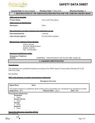
This tool is equipped with an approved 3-conductor cord rated up<br />
to 300V <strong>and</strong> a 3-prong grounding type plug rated at 115V (See<br />
Figure 1) for your protection against shock hazards.<br />
Grounding plug should be plugged directly into a properly<br />
installed <strong>and</strong> grounded 3-prong grounding-type receptacle, as<br />
shown (Figure 1).<br />
Properly Grounded Outlet<br />
Grounding Prong<br />
3-Prong Plug<br />
Figure 1 – 3-Prong Receptacle<br />
Do not remove or alter grounding prong in any manner. In the<br />
event of a malfunction or breakdown, grounding provides a path<br />
of least resistance for electrical shock.<br />
WARNING: Do not permit fingers to touch the terminals of plug<br />
when installing or removing from outlet.<br />
Plug must be plugged into matching outlet that is properly<br />
installed <strong>and</strong> grounded in accordance with all local codes <strong>and</strong><br />
ordinances. Do not modify plug provided. If it will not fit in outlet,<br />
have proper outlet installed by a qualified electrician.<br />
Inspect tool cords periodically, <strong>and</strong> if damaged, have repaired by<br />
an authorized service facility.<br />
Green (or green <strong>and</strong> yellow) conductor in cord is the grounding<br />
wire. If repair or replacement of the electric cord or plug is necessary,<br />
do not connect the green (or green <strong>and</strong> yellow) wire to a live<br />
terminal.<br />
Where a 2-prong wall receptacle is encountered, it must be<br />
replaced with a properly grounded 3-prong receptacle installed in<br />
accordance with National Electric Code <strong>and</strong> local codes <strong>and</strong> ordinances.<br />
WARNING: This work should be performed by a qualified electrician.<br />
A temporary 3-prong to 2-prong grounding adapter (See Figure 2)<br />
is available for connecting plugs to a two pole outlet if it is<br />
properly grounded.<br />
Grounding Lug<br />
Adapter<br />
3-Prong Plug<br />
Make sure this is<br />
Connected to a known<br />
Grounded Receptacle<br />
EXTENSION CORDS<br />
• The use of any extension cord will cause some drop in voltage<br />
<strong>and</strong> loss of power.<br />
• Wires of the extension cord must be of sufficient size to carry<br />
the current <strong>and</strong> maintain adequate voltage.<br />
• Use the table to determine the minimum wire size (A.W.G.)<br />
extension cord.<br />
• Use only 3-wire extension cords having 3-prong grounding<br />
type plugs <strong>and</strong> 3-pole receptacles which accept the tool plug.<br />
• If the extension cord is worn, cut, or damaged in any way,<br />
replace it immediately.<br />
EXTENSION CORD LENGTH<br />
Wire Size. . . . . . . . . . . . . . . . . . . . . . . . . . . . . . . . . . . . . . . . . . . . . . . . . . . A.W.G.<br />
Up to 25 ft.. . . . . . . . . . . . . . . . . . . . . . . . . . . . . . . . . . . . . . . . . . . . . . . . . . . . . 14<br />
25-50 ft. . . . . . . . . . . . . . . . . . . . . . . . . . . . . . . . . . . . . . . . . . . . . . . . . . . . . . . . 12<br />
NOTE: Using extension cords over 50 ft. long is not recommended.<br />
POWER SOURCE<br />
Drill press requires a 115/230 volt, 60 Hz power source.<br />
To use the <strong>drill</strong> press with a 230V power supply, have a qualified<br />
electrician attach a 230 volt, 20/30A three-prong plug onto <strong>drill</strong><br />
press line cord.<br />
ELECTRICAL CONNECTIONS<br />
Refer to Figure 3.<br />
WARNING: All electrical connections must be performed by a<br />
qualified electrician. Make sure unit is off <strong>and</strong> disconnected from<br />
power source while motor is mounted, connected, reconnected or<br />
anytime wiring is inspected.<br />
• The motor should be wired for 115 volts an clockwise rotation<br />
as viewed from shaft end of motor.<br />
• A label on the motor describes the possible wiring configurations.<br />
There are many different possible combinations, so only<br />
the diagram provided with the motor should be used.<br />
• Be sure to install motor cord so that the cover plate for the motor<br />
wiring holds the cord in the groove of the motor end shield.The<br />
motor cord must be secured to protect the wiring connections<br />
from possible strain.<br />
• The power supply to motor is controlled by a locking rocker<br />
switch. Power lines are connected to the quick connect terminals<br />
of the switch.<br />
• The green ground line must remain securely fastened to the<br />
motor ground terminal to provide proper grounding.<br />
• To operate <strong>drill</strong> press at 230 volts, rewire motor as shown in<br />
Figure 3 <strong>and</strong> replace line cord plug with a 230 volt, 15A, 3-prong<br />
plug. If motor label has a different wiring configuration, use the<br />
motor label diagram to rewire motor.<br />
1 3 5 2 4 6<br />
1<br />
2 3 5 4 6<br />
2-Prong Receptacle<br />
Figure 2 – 2-Prong Receptacle with adapter<br />
Do not use a 3-prong to 2-prong grounding adapter unless permitted<br />
by local <strong>and</strong> national codes <strong>and</strong> ordinances.<br />
(A 3-prong to 2-prong grounding adapter is not permitted in<br />
Canada.) Where permitted, the rigid green tab or terminal on the<br />
side of the adapter must be securely connected to a permanent<br />
electrical ground such as a properly grounded water pipe, a properly<br />
grounded outlet box or a properly grounded wire system.<br />
Many cover plate screws, water pipes <strong>and</strong> outlet boxes are not<br />
properly grounded. To ensure proper ground, grounding means<br />
must be tested by a qualified electrician.<br />
U<br />
115 Volts<br />
To Change Rotation, Exchange Leads 5 <strong>and</strong> 6<br />
U, V-Power Supply<br />
Figure 3 – Wiring Schematic for Motor<br />
V<br />
U<br />
230 Volts<br />
V<br />
4
Palmgren Operating Manual & Parts List 80153 & 80154<br />
Spindle<br />
Rotation<br />
D<br />
C<br />
B<br />
Spindle<br />
4<br />
3<br />
2<br />
Z<br />
Y<br />
X<br />
Motor<br />
A<br />
1<br />
W<br />
Figure 4 – Spindle Speed Adjustment<br />
Recommended Drill Size per Material for 12 Speeds<br />
Belt<br />
Location RPM Wood<br />
D4-1W<br />
C3-1W<br />
D4-2X<br />
B2-1W<br />
C3-2X<br />
D4-3Y<br />
A1-2X<br />
B2-3Y<br />
C3-4Z<br />
A1-3Y<br />
B2-4Z<br />
A1-4Z<br />
3080<br />
2225<br />
1905<br />
1570<br />
1360<br />
1205<br />
620<br />
600<br />
525<br />
390<br />
370<br />
240<br />
in/mm<br />
5/16 7.9<br />
5/8 15.9<br />
5/8 15.9<br />
7/8 22.2<br />
7/8 22.2<br />
7/8 22.2<br />
1 1 /4 31.8<br />
1 1 /4 31.8<br />
1 1 /4 31.8<br />
1 5 /8 41.3<br />
1 5 /8 41.3<br />
2 50.8<br />
OPERATION<br />
Zinc<br />
Diecast<br />
in/mm<br />
3/16 4.8<br />
3/8 9.5<br />
3/8 9.5<br />
1/2 12.7<br />
1/2 12.7<br />
1/2 12.7<br />
3/4 19.0<br />
3/4 19.0<br />
3/4 19.0<br />
7/8 22.2<br />
7/8 22.2<br />
1 25.4<br />
Alum. &<br />
Brass<br />
in/mm<br />
11/64 4.4<br />
11/32 8.7<br />
11/32 8.7<br />
15/32 11.9<br />
15/32 11.9<br />
15/32 11.9<br />
11/16 17.5<br />
11/16 17.5<br />
11/16 17.5<br />
3/4 19.0<br />
3/4 19.0<br />
– –<br />
Refer to Figures 4, 5 <strong>and</strong> 6.<br />
WARNING: Read <strong>and</strong> underst<strong>and</strong> operating instructions <strong>and</strong><br />
parts manual before operating this machine.<br />
CAUTION: The operation of any power tool can result in foreign<br />
objects being thrown into the eyes, which can result in severe eye<br />
damage. Always wear safety glasses complying with United States<br />
ANSI Z87.1 (shown on package) before commencing power tool<br />
operation.<br />
SPEED ADJUSTMENTS<br />
Refer to Figures 4 <strong>and</strong> 6.<br />
WARNING: Be sure <strong>drill</strong> press is turned off <strong>and</strong> is disconnected<br />
from power source before adjusting speeds.<br />
• To change spindle speed, loosen motor lock h<strong>and</strong>le (Ref. No.<br />
70), pivot the motor toward front of <strong>drill</strong> press. This will loosen<br />
the belt <strong>and</strong> permit relocating the belt to the desired pulley<br />
groove for the required spindle speed (See Figure 4).<br />
• After belt has been repositioned, pull h<strong>and</strong>le (Ref. No. 71) to<br />
move motor toward rear of <strong>drill</strong> press <strong>and</strong> tighten motor lock<br />
h<strong>and</strong>le.<br />
• Check belt for proper tension <strong>and</strong> make any final adjustment. A<br />
belt is properly tensioned when light pressure applied to midpoint<br />
of the belt produces about 1/2” deflection.<br />
TABLE ADJUSTMENTS<br />
Refer to Figure 5.<br />
• Height adjustments: To adjust table, loosen locking h<strong>and</strong>le (Ref.<br />
No. 15) <strong>and</strong> turn crank h<strong>and</strong>le (Ref. No. 5) to desired height.<br />
Immediately retighten table bracket locking h<strong>and</strong>le.<br />
• Rotation of work table : Loosen table locking h<strong>and</strong>le (Ref. No.<br />
25) <strong>and</strong> rotate table (Ref. No. 16) to desired position <strong>and</strong><br />
retighten h<strong>and</strong>le.<br />
Plastic<br />
in/mm<br />
5/32 4.0<br />
5/16 7.9<br />
5/16 7.9<br />
7/16 11.1<br />
7/16 11.1<br />
7/16 11.1<br />
5/8 15.9<br />
5/8 15.9<br />
5/8 15.9<br />
13/16 20.6<br />
13/16 20.6<br />
– –<br />
Cast Iron<br />
& Bronze<br />
in/mm<br />
7/64 2.8<br />
1/4 6.4<br />
1/4 6.4<br />
11/32 8.7<br />
11/32 8.7<br />
11/32 8.7<br />
1/2 12.7<br />
1/2 12.7<br />
1/2 12.7<br />
5/8 15.9<br />
5/8 15.9<br />
– –<br />
Steel<br />
Mild &<br />
Malleable<br />
in/mm<br />
3/32 2.4<br />
5/32 4.0<br />
5/32 4.0<br />
1/4 6.4<br />
1/4 6.4<br />
1/4 6.4<br />
3/8 9.5<br />
3/8 9.5<br />
3/8 9.5<br />
1/2 12.7<br />
1/2 12.7<br />
– –<br />
Steel Cast &<br />
Med.<br />
Carbon<br />
in/mm<br />
1/16 1.6<br />
1/8 3.2<br />
1/8 3.2<br />
3/16 4.8<br />
3/16 4.8<br />
3/16 4.8<br />
5/16 7.9<br />
5/16 7.9<br />
5/16 7.9<br />
7/16 11.1<br />
7/16 11.1<br />
9/16 14.3<br />
Steel<br />
Stainless &<br />
<strong>Tool</strong><br />
in/mm<br />
1/32 0.8<br />
1/16 1.6<br />
1/16 1.6<br />
1/8 3.2<br />
1/8 3.2<br />
1/8 3.2<br />
1/4 6.4<br />
1/4 6.4<br />
1/4 6.4<br />
3/8 9.5<br />
3/8 9.5<br />
1/2 12.7<br />
• Tilting work table: Loosen hex head bolt (Ref. No. 23). Remove<br />
pin <strong>and</strong> nut (Ref. No. 26). To do this, tighten nut until pin slips<br />
out easily. Tilt table to desired angle up to 45° <strong>and</strong> retighten<br />
hex head bolt. Reinsert pin <strong>and</strong> nut when returning the table to<br />
0° position.<br />
• To obtain more distance between chuck <strong>and</strong> table, the work<br />
table can be rotated 180° <strong>and</strong> base can be used as a work surface.<br />
This permits <strong>drill</strong>ing of larger objects.<br />
• Clamp table securely after adjustments have been made.<br />
DEPTH STOP ADJUSTMENT<br />
Refer to Figure 6.<br />
To control <strong>drill</strong>ing depth, use scale (Ref. No. 25) to adjust to desired<br />
depth. Depress <strong>and</strong> hold pin, slide depth stop nut along lead screw<br />
(Ref. Nos. 24, 26 <strong>and</strong> 28) until bottom edge of nut coincides with<br />
the desired depth on the scale, then release pin. Use this feature to<br />
<strong>drill</strong> more than one hole to the same depth.<br />
MOUNT DRILL BIT<br />
WARNING: Be sure <strong>drill</strong> press is turned off <strong>and</strong> is disconnected<br />
from power source before adjusting speeds.<br />
• Place <strong>drill</strong> bit in jaws of <strong>drill</strong> chuck.<br />
• Tighten chuck with <strong>drill</strong> chuck key. Be sure to tighten the chuck<br />
using all three key positions on the chuck body <strong>and</strong> remove<br />
chuck key.<br />
5
Palmgren Operating Manual & Parts List 80153 & 80154<br />
MAINTENANCE<br />
WARNING: Turn switch off <strong>and</strong> remove plug from power source<br />
outlet before maintaining or lubricating your <strong>drill</strong> press<br />
V-BELT<br />
Replace V-belt when worn.<br />
LUBRICATION<br />
Refer to Figures 5 <strong>and</strong> 6.<br />
The ball bearings are lubricated at the factory <strong>and</strong> need no further<br />
lubrication. Using 20wt. non detergent oil, periodically lubricate<br />
the splines (grooves) in the spindle <strong>and</strong> the rack (teeth on the<br />
quill) as follows:<br />
• Lower quill assembly (Figure 6, Ref. No. 19) all the way down.<br />
• Apply lubricant around the inside of the hole in the spindle<br />
pulley (Figure 6, Ref. No. 45).<br />
• Apply lubricant to rack (teeth) on quill (Figure 6, Ref. No. 14)<br />
while extended below <strong>drill</strong> press head.<br />
• Apply lubricant to rack <strong>and</strong> pinion gear (Figure 5, Ref. Nos. 4<br />
<strong>and</strong> 9) on column <strong>and</strong> table assembly.<br />
CLEAN MOTOR<br />
Frequently blow out any dust that may accumulate inside motor. If<br />
power cord is worn, cut or damaged in any way, have it replaced<br />
immediately.<br />
6
Palmgren Operating Manual & Parts List 80153 & 80154<br />
TROUBLESHOOTING<br />
SYMPTOM<br />
Spindle does not turn<br />
Noisy spindle<br />
Noisy operation<br />
Bit burns or smokes<br />
Excessive <strong>drill</strong> runout or wobble<br />
Drill bit binds in workpiece<br />
POSSIBLE CAUSES<br />
1. No power to <strong>drill</strong> press<br />
2. Defective switch<br />
3. Defective motor<br />
Defective bearings<br />
1. Incorrect bet tension<br />
2. Dry spindle<br />
3. Loose spindle<br />
4. Loose motor pulley<br />
1. Incorrect speed<br />
2. Chips not coming out of table<br />
3. Dull bit<br />
4. Feeding too slow<br />
5. Bit not lubricated<br />
6. Bit running backwards<br />
1. Bent bit<br />
2. Bit not properly installed in chuck<br />
3. Chuck not properly installed<br />
4. Worn spindle bearings<br />
1. Workpiece pinching bit or excessive feed<br />
2. Improper belt tension<br />
3. Workpiece not supported or clamped<br />
properly<br />
CORRECTIVE ACTION<br />
1. Check wiring, fuse or circuit breaker<br />
2. Replace switch<br />
3. Replace motor<br />
Replace bearings<br />
1. Adjust tension<br />
2. Lubricate spindle, See Lubrication, page 5<br />
3. Tighten pulley nut<br />
4. Tighten set screw in pulley<br />
1. Change speed<br />
2. Retract bit frequently to clear chips<br />
3. Sharpen or replace bit<br />
4. Feed faster; enough to allow <strong>drill</strong> to cut<br />
5. Lubricate bit<br />
6. Check motor rotation to be sure it is<br />
clockwise facing shaft end<br />
1. Replace bit<br />
2. Install bit properly<br />
3. Install chuck properly<br />
4. Replace bearings<br />
1. Support or clamp work, decrease feed<br />
pressure<br />
2. Adjust tension<br />
3. Support or clamp workpiece securely<br />
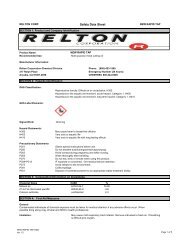
7
Palmgren Operating Manual & Parts List 80153 & 80154<br />
16<br />
15<br />
14<br />
13<br />
6<br />
18<br />
17<br />
11<br />
9<br />
10<br />
19<br />
20<br />
22<br />
8<br />
21<br />
12<br />
7<br />
5<br />
25<br />
23<br />
24<br />
6<br />
2<br />
26<br />
3<br />
27<br />
4<br />
1<br />
Figure 5 - Replacement Parts Illustration for Base<br />
8
Palmgren Operating Manual & Parts List 80153 & 80154<br />
∆ Not Shown.<br />
* St<strong>and</strong>ard hardware item available locally.<br />
REPLACEMENT PARTS LIST FOR BASE<br />
Ref.<br />
Part Number for:<br />
No. Description 80153 80154 Qty.<br />
1 Base 18750.09 18750.09 1<br />
2 Column Assembly 18751.09 18752.09 1<br />
3 10-1.50 x 40mm Socket Head Bolt * * 4<br />
4 Rack 17229.00 17230.00 1<br />
5 H<strong>and</strong>le 17231.00 17231.00 1<br />
6 8-1.25 x 8mm Set Screw * * 2<br />
7 Crank 17232.00 17232.00 1<br />
8 Threaded Bushing 18753.00 18753.00 1<br />
9 Pinion Gear <strong>and</strong> Shaft 17234.00 17234.00 1<br />
10 Worm <strong>and</strong> Pinion Gear Set (Ref. Nos. 9 <strong>and</strong> 11) 17235.00 17235.00 1<br />
11 Worm Gear 17236.00 17236.00 1<br />
12 3AMI-14 Retaining Ring 05989.00 05989.00 1<br />
13 Rack Retaining Ring 18754.00 18754.00 1<br />
14 Bushing 18755.00 18755.00 1<br />
15 Table Bracket Locking H<strong>and</strong>le 17239.00 17239.00 1<br />
16 Table 18761.09 18761.09 1<br />
17 Hose Fitting 17241.00 17241.00 1<br />
18 Hose 17242.00 17242.00 1<br />
19 Table Arm <strong>and</strong> Bracket Assembly 18756.09 18756.09 1<br />
(includes Ref. Nos. 20 thru 26)<br />
20 Rivet 01286.00 01286.00 4<br />
21 Indicator 17244.00 17244.00 1<br />
22 Scale 19071.00 19071.00 1<br />
23 16-2.0 x 50mm Hex Head Bolt * * 1<br />
24 16mm Lock Washer * * 1<br />
25 Table Locking H<strong>and</strong>le 00311.00 00311.00 1<br />
26 Pin <strong>and</strong> Nut 17246.00 17246.00 1<br />
27 10mm Lock Washer * * 4<br />
Recommended Accessories<br />
∆ 4” Angle Vise 11351 11351 1<br />
∆ 4” Drill Press Vise 12352 12352 1<br />
∆ 4” St<strong>and</strong>ard Vise 12403 12403 1<br />
∆ 6”Quick Grip Vise 12621 12621 1<br />
∆ 6” St<strong>and</strong>ard Vise 12601 12601 1<br />
∆ 6” Cross Vise 30601 30601 1<br />
9
Palmgren Operating Manual & Parts List 80153 & 80154<br />
55<br />
56<br />
46<br />
46<br />
45<br />
47<br />
53<br />
77<br />
54<br />
58<br />
57<br />
59<br />
41<br />
43<br />
13<br />
42<br />
13<br />
41<br />
40<br />
52<br />
51<br />
44<br />
49<br />
3<br />
50<br />
78<br />
37<br />
36<br />
61<br />
62<br />
63<br />
60<br />
74<br />
73<br />
3<br />
49<br />
32<br />
48<br />
72<br />
75<br />
71<br />
70<br />
39<br />
38<br />
30<br />
29<br />
27<br />
35<br />
34<br />
31<br />
30<br />
33<br />
76<br />
64<br />
65<br />
67<br />
66<br />
5<br />
68<br />
69<br />
26<br />
25<br />
23<br />
22<br />
28<br />
24<br />
18<br />
17<br />
16<br />
15<br />
8<br />
7<br />
6<br />
1<br />
4<br />
3<br />
14<br />
21<br />
19<br />
2<br />
13<br />
20<br />
12<br />
11<br />
9<br />
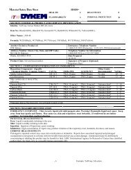
10<br />
Figure 6 - Replacement Parts Illustration for Head<br />
10
Palmgren Operating Manual & Parts List 80153 & 80154<br />
REPLACEMENT PARTS LIST FOR HEAD<br />
Ref.<br />
No. Description Part No. Qty.<br />
1 Quill H<strong>and</strong>le 17247.09 1<br />
2 Grip 17248.01 3<br />
3 6-1.0 x 10mm Socket Head Bolt * 6<br />
4 Spacer 17249.00 1<br />
5 7 x 8 x 24mm Key 18757.00 1<br />
6 Pinion 17250.00 1<br />
7 10-1.5mm Hex Nut * 1<br />
8 Retaining Screw 19072.00 1<br />
9 JT3 Chuck with Key 19073.00 1<br />
10 Self-Ejecting Chuck Key 19074.00 1<br />
11 MT2/JT3 Arbor 18908.00 1<br />
12 Spindle 17251.00 1<br />
13 6205ZZ Ball Bearing 02443.00 3<br />
14 Quill 17252.00 1<br />
15 Rubber Bumper 17253.00 1<br />
16 6203ZZ Ball Bearing 01901.00 1<br />
17 Keyed Washer 17254.00 1<br />
18 Spindle Lock Nut 17255.00 1<br />
19 Lower Spindle <strong>and</strong> Quill Assembly 17256.00 1<br />
(Ref. Nos. 12 through 18)<br />
20 Drift Key 18909.00 1<br />
21 6-1.0 x 20mm Socket Head Bolt * 1<br />
22 12-1.75mm Hex Nut * 1<br />
23 Depth Stop Collar 17257.09 1<br />
24 Depth Stop Lead Screw 20003.00 1<br />
25 Scale 17259.00 1<br />
26 Pin 17260.00 1<br />
27 Spring 17261.00 1<br />
28 Depth Stop Nut 17262.00 1<br />
29 Switch 16080.00 1<br />
30 4-0.7 x 10mm Pan Head Screw * 5<br />
31 Switch Plate 17263.00 1<br />
32 10-1.5 x 20mm Flat Head Screw * 4<br />
33 3AMI-25 Retaining Ring 01900.00 1<br />
34 Bracket 20004.00 1<br />
35 6-1.0 x 12mm Socket Head Bolt * 2<br />
36 Flange 17265.00 1<br />
37 2.5 x 14mm Spring Pin 03378.00 1<br />
38 4-0.7 x 12mm Flat Head Screw * 3<br />
39 Cap Cover with Spring 17266.00 1<br />
40 12-1.25mm Hex Nut * 2<br />
Ref.<br />
No. Description Part No. Qty.<br />
41 3BMI-52 Retaining Ring 02445.00 2<br />
42 Spacer 17267.00 1<br />
43 Spindle Sleeve 19075.00 1<br />
44 Upper Spindle Assembly 19076.00 1<br />
(Ref. Nos. 13, 33, 42 <strong>and</strong> 43)<br />
45 Spindle Pulley 17270.00 1<br />
46 V-belt 07911.00 2<br />
47 Spindle Sleeve Nut 19077.00 1<br />
48 Plate 17272.00 1<br />
49 6mm Flat Washer * 5<br />
50 Grommet 19079.00 2<br />
51 Cord Clamp 04078.01 1<br />
52 6-1.0mm Hex Nut * 1<br />
53 Pulley Housing 18758.00 1<br />
54 Pulley Shaft 17274.00 1<br />
55 Transmitting Pulley 17275.00 1<br />
56 6202ZZ Ball Bearing 01540.00 1<br />
57 Motor Pulley 17276.00 1<br />
58 3/16 x 1 3 /8mm Key 01409.00 1<br />
59 8-1.25 x 8mm Set Screw * 2<br />
60 12mm Flat Washer * 1<br />
61 Strain Relief 17277.00 2<br />
62 Threaded Bushing 19080.00 1<br />
63 Head 18759.09 1<br />
64 6 x 20mm Spring Pin 01596.00 2<br />
65 Bushing 19081.00 1<br />
66 10-1.5 x 75mm Socket Head Bolt 18760.00 1<br />
67 Line Cord 17282.00 1<br />
68 Motor 23564.00 1<br />
69 Switch Cord 17284.00 1<br />
70 Motor Locking H<strong>and</strong>le 17285.00 1<br />
71 H<strong>and</strong>le 17286.00 1<br />
72 Motor Mount Plate 17287.00 1<br />
73 12-1.75 x 25mm Socket Head Bolt * 1<br />
74 12mm Lock Washer * 1<br />
75 3/8-16 x 3/4” Flat Head Screw * 4<br />
76 4mm Serrated washer * 2<br />
77 Knob 18762.00 1<br />
78 6-1.0 x 10mm Pan Head Screw * 1<br />
∆ Hardware Bag 20210.00 1<br />
∆ Operator’s Manual 20143.19 1<br />
∆ Not Shown.<br />
* St<strong>and</strong>ard hardware item available locally.<br />
11
Palmgren Operating Manual & Parts List 80153 & 80154<br />
TWO YEAR LIMITED WARRANTY<br />
Palmgren warrants to the original purchaser that all products covered under this warranty are free from defects in material <strong>and</strong> workmanship<br />
for a period of two years from the date of the original purchase.<br />
We will repair or replace at our option, any part or parts of the product <strong>and</strong> accessories covered under this warranty which, after examination,<br />
proves to be defective in workmanship or material during the warranty period.<br />
This warranty does not apply to repair or replacement required due to misuse, abuse, normal wear <strong>and</strong> tear, or repairs attempted or made by<br />
other than our Service Department or an Authorized Service Representative. Proper use <strong>and</strong> care instructions are provided in the operator’s<br />
manual. Failure to follow these instructions will void the warranty.<br />
This warranty gives you specific legal rights <strong>and</strong> you may also have other legal rights which may vary from state to state.<br />
Responsibility of Original Purchaser (Initial User):<br />
• To process warranty claim on this product, DO NOT return it to the retailer. The product must be evaluated by Palmgren.<br />
Call (800) 621-6145 for instructions.<br />
• Retain original cash register sales receipt or invoice as proof of purchase for warranty work.<br />
• Use reasonable care in the operation <strong>and</strong> maintenance of the product as described in the operator’s manual.<br />
• Deliver or ship the product(s) to Palmgren. Freight costs, if any must be paid by the purchaser.<br />
This Warranty Does Not Cover:<br />
• Merch<strong>and</strong>ise sold as reconditioned, used as rental equipment, <strong>and</strong> <strong>floor</strong> or display <strong>model</strong>s.<br />
• Repair <strong>and</strong> transportation costs of merch<strong>and</strong>ise determined not to be defective.<br />
• Expendable parts or accessories supplied with the product which are expected to become inoperative or unusable after a reasonable<br />
period of use. See the operator’s manual for a list of accessories <strong>and</strong> expendable parts.