ALTERA CORPORATION (EPM7256BTC100-10N) MAX7000 CPLD ...
ALTERA CORPORATION (EPM7256BTC100-10N) MAX7000 CPLD ...
ALTERA CORPORATION (EPM7256BTC100-10N) MAX7000 CPLD ...

You also want an ePaper? Increase the reach of your titles
YUMPU automatically turns print PDFs into web optimized ePapers that Google loves.
Distributed by:<br />
www.Jameco.com ✦ 1-800-831-4242<br />
The content and copyrights of the attached<br />
material are the property of its owner.
®<br />
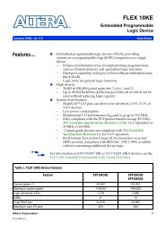
MAX 7000<br />
Programmable Logic<br />
Device Family<br />
September 2005, ver. 6.7 Data Sheet<br />
Features... ■ High-performance, EEPROM-based programmable logic devices<br />
(PLDs) based on second-generation MAX ® architecture<br />
■ 5.0-V in-system programmability (ISP) through the built-in<br />
IEEE Std. 1149.1 Joint Test Action Group (JTAG) interface available in<br />
MAX 7000S devices<br />
– ISP circuitry compatible with IEEE Std. 1532<br />
■ Includes 5.0-V MAX 7000 devices and 5.0-V ISP-based MAX 7000S<br />
devices<br />
■ Built-in JTAG boundary-scan test (BST) circuitry in MAX 7000S<br />
devices with 128 or more macrocells<br />
■ Complete EPLD family with logic densities ranging from 600 to<br />
5,000 usable gates (see Tables 1 and 2)<br />
■ 5-ns pin-to-pin logic delays with up to 175.4-MHz counter<br />
frequencies (including interconnect)<br />
■ PCI-compliant devices available<br />
Altera Corporation 1<br />
DS-<strong>MAX7000</strong>-6.7<br />
f<br />
Table 1. MAX 7000 Device Features<br />
For information on in-system programmable 3.3-V MAX 7000A or 2.5-V<br />
MAX 7000B devices, see the MAX 7000A Programmable Logic Device Family<br />
Data Sheet or the MAX 7000B Programmable Logic Device Family Data<br />
Sheet.<br />
Feature EPM7032 EPM7064 EPM7096 EPM7128E EPM7160E EPM7192E EPM7256E<br />
Usable<br />
gates<br />
600 1,250 1,800 2,500 3,200 3,750 5,000<br />
Macrocells 32 64 96 128 160 192 256<br />
Logic array<br />
blocks<br />
2 4 6 8 10 12 16<br />
Maximum<br />
user I/O pins<br />
36 68 76 100 104 124 164<br />
tPD (ns) 6 6 7.5 7.5 10 12 12<br />
tSU (ns) 5 5 6 6 7 7 7<br />
tFSU (ns) 2.5 2.5 3 3 3 3 3<br />
tCO1 (ns) 4 4 4.5 4.5 5 6 6<br />
fCNT (MHz) 151.5 151.5 125.0 125.0 100.0 90.9 90.9
MAX 7000 Programmable Logic Device Family Data Sheet<br />
Table 2. MAX 7000S Device Features<br />
Feature EPM7032S EPM7064S EPM7128S EPM7160S EPM7192S EPM7256S<br />
Usable gates 600 1,250 2,500 3,200 3,750 5,000<br />
Macrocells 32 64 128 160 192 256<br />
Logic array<br />
blocks<br />
2 4 8 10 12 16<br />
Maximum<br />
user I/O pins<br />
36 68 100 104 124 164<br />
tPD (ns) 5 5 6 6 7.5 7.5<br />
tSU (ns) 2.9 2.9 3.4 3.4 4.1 3.9<br />
tFSU (ns) 2.5 2.5 2.5 2.5 3 3<br />
tCO1 (ns) 3.2 3.2 4 3.9 4.7 4.7<br />
fCNT (MHz) 175.4 175.4 147.1 149.3 125.0 128.2<br />
...and More<br />
Features<br />
■ Open-drain output option in MAX 7000S devices<br />
■ Programmable macrocell flipflops with individual clear, preset,<br />
clock, and clock enable controls<br />
■ Programmable power-saving mode for a reduction of over 50% in<br />
each macrocell<br />
■ Configurable expander product-term distribution, allowing up to<br />
32 product terms per macrocell<br />
■ 44 to 208 pins available in plastic J-lead chip carrier (PLCC), ceramic<br />
pin-grid array (PGA), plastic quad flat pack (PQFP), power quad flat<br />
pack (RQFP), and 1.0-mm thin quad flat pack (TQFP) packages<br />
■ Programmable security bit for protection of proprietary designs<br />
■ 3.3-V or 5.0-V operation<br />
– MultiVolt TM I/O interface operation, allowing devices to<br />
interface with 3.3-V or 5.0-V devices (MultiVolt I/O operation is<br />
not available in 44-pin packages)<br />
– Pin compatible with low-voltage MAX 7000A and MAX 7000B<br />
devices<br />
■ Enhanced features available in MAX 7000E and MAX 7000S devices<br />
– Six pin- or logic-driven output enable signals<br />
– Two global clock signals with optional inversion<br />
– Enhanced interconnect resources for improved routability<br />
– Fast input setup times provided by a dedicated path from I/O<br />
pin to macrocell registers<br />
– Programmable output slew-rate control<br />
■ Software design support and automatic place-and-route provided by<br />
Altera’s development system for Windows-based PCs and Sun<br />
SPARCstation, and HP 9000 Series 700/800 workstations<br />
2 Altera Corporation
General<br />
Description<br />
Table 3. MAX 7000 Speed Grades<br />
MAX 7000 Programmable Logic Device Family Data Sheet<br />
■ Additional design entry and simulation support provided by EDIF<br />
2 0 0 and 3 0 0 netlist files, library of parameterized modules (LPM),<br />
Verilog HDL, VHDL, and other interfaces to popular EDA tools from<br />
manufacturers such as Cadence, Exemplar Logic, Mentor Graphics,<br />
OrCAD, Synopsys, and VeriBest<br />
■ Programming support<br />
– Altera’s Master Programming Unit (MPU) and programming<br />
hardware from third-party manufacturers program all<br />
MAX 7000 devices<br />
– The BitBlaster TM serial download cable, ByteBlasterMV TM<br />
parallel port download cable, and MasterBlaster TM<br />
serial/universal serial bus (USB) download cable program MAX<br />
7000S devices<br />
The MAX 7000 family of high-density, high-performance PLDs is based<br />
on Altera’s second-generation MAX architecture. Fabricated with<br />
advanced CMOS technology, the EEPROM-based MAX 7000 family<br />
provides 600 to 5,000 usable gates, ISP, pin-to-pin delays as fast as 5 ns,<br />
and counter speeds of up to 175.4 MHz. MAX 7000S devices in the -5, -6,<br />
-7, and -10 speed grades as well as MAX 7000 and MAX 7000E devices in<br />
-5, -6, -7, -10P, and -12P speed grades comply with the PCI Special Interest<br />
Group (PCI SIG) PCI Local Bus Specification, Revision 2.2. See Table 3<br />
for available speed grades.<br />
Device Speed Grade<br />
-5 -6 -7 -10P -10 -12P -12 -15 -15T -20<br />
EPM7032 v v v v v v<br />
EPM7032S v v v v<br />
EPM7064 v v v v v<br />
EPM7064S v v v v<br />
EPM7096 v v v v<br />
EPM7128E v v v v v v<br />
EPM7128S v v v v<br />
EPM7160E v v v v v<br />
EPM7160S v v v v<br />
EPM7192E v v v v<br />
EPM7192S v v v<br />
EPM7256E v v v v<br />
EPM7256S v v v<br />
Altera Corporation 3
MAX 7000 Programmable Logic Device Family Data Sheet<br />
The MAX 7000E devices—including the EPM7128E, EPM7160E,<br />
EPM7192E, and EPM7256E devices—have several enhanced features:<br />
additional global clocking, additional output enable controls, enhanced<br />
interconnect resources, fast input registers, and a programmable slew<br />
rate.<br />
In-system programmable MAX 7000 devices—called MAX 7000S<br />
devices—include the EPM7032S, EPM7064S, EPM7128S, EPM7160S,<br />
EPM7192S, and EPM7256S devices. MAX 7000S devices have the<br />
enhanced features of MAX 7000E devices as well as JTAG BST circuitry in<br />
devices with 128 or more macrocells, ISP, and an open-drain output<br />
option. See Table 4.<br />
Table 4. MAX 7000 Device Features<br />
Feature EPM7032 All<br />
All<br />
EPM7064 MAX 7000E MAX 7000S<br />
EPM7096 Devices Devices<br />
ISP via JTAG interface v<br />
JTAG BST circuitry v(1)<br />
Open-drain output option v<br />
Fast input registers v v<br />
Six global output enables v v<br />
Two global clocks v v<br />
Slew-rate control v v<br />
MultiVolt interface (2) v v v<br />
Programmable register v v v<br />
Parallel expanders v v v<br />
Shared expanders v v v<br />
Power-saving mode v v v<br />
Security bit v v v<br />
PCI-compliant devices available v v v<br />
Notes:<br />
(1) Available only in EPM7128S, EPM7160S, EPM7192S, and EPM7256S devices only.<br />
(2) The MultiVolt I/O interface is not available in 44-pin packages.<br />
4 Altera Corporation
MAX 7000 Programmable Logic Device Family Data Sheet<br />
The MAX 7000 architecture supports 100% TTL emulation and<br />
high-density integration of SSI, MSI, and LSI logic functions. The<br />
MAX 7000 architecture easily integrates multiple devices ranging from<br />
PALs, GALs, and 22V10s to MACH and pLSI devices. MAX 7000 devices<br />
are available in a wide range of packages, including PLCC, PGA, PQFP,<br />
RQFP, and TQFP packages. See Table 5.<br />
Table 5. MAX 7000 Maximum User I/O Pins Note (1)<br />
Device 44-<br />
Pin<br />
PLCC<br />
44-<br />
Pin<br />
PQFP<br />
44-<br />
Pin<br />
TQFP<br />
68-<br />
Pin<br />
PLCC<br />
84-<br />
Pin<br />
PLCC<br />
100-<br />
Pin<br />
PQFP<br />
100-<br />
Pin<br />
TQFP<br />
160-<br />
Pin<br />
PQFP<br />
Notes:<br />
(1) When the JTAG interface in MAX 7000S devices is used for either boundary-scan testing or for ISP, four I/O pins<br />
become JTAG pins.<br />
(2) Perform a complete thermal analysis before committing a design to this device package. For more information, see<br />
the Operating Requirements for Altera Devices Data Sheet.<br />
MAX 7000 devices use CMOS EEPROM cells to implement logic<br />
functions. The user-configurable MAX 7000 architecture accommodates a<br />
variety of independent combinatorial and sequential logic functions. The<br />
devices can be reprogrammed for quick and efficient iterations during<br />
design development and debug cycles, and can be programmed and<br />
erased up to 100 times.<br />
Altera Corporation 5<br />
160-<br />
Pin<br />
PGA<br />
192-<br />
Pin<br />
PGA<br />
208-<br />
Pin<br />
PQFP<br />
208-<br />
Pin<br />
RQFP<br />
EPM7032 36 36 36<br />
EPM7032S 36 36<br />
EPM7064 36 36 52 68 68<br />
EPM7064S 36 36 68 68<br />
EPM7096 52 64 76<br />
EPM7128E 68 84 100<br />
EPM7128S 68 84 84 (2) 100<br />
EPM7160E 64 84 104<br />
EPM7160S 64 84 (2) 104<br />
EPM7192E 124 124<br />
EPM7192S 124<br />
EPM7256E 132 (2) 164 164<br />
EPM7256S 164 (2) 164
MAX 7000 Programmable Logic Device Family Data Sheet<br />
Functional<br />
Description<br />
f<br />
MAX 7000 devices contain from 32 to 256 macrocells that are combined<br />
into groups of 16 macrocells, called logic array blocks (LABs). Each<br />
macrocell has a programmable-AND/fixed-OR array and a configurable<br />
register with independently programmable clock, clock enable, clear, and<br />
preset functions. To build complex logic functions, each macrocell can be<br />
supplemented with both shareable expander product terms and highspeed<br />
parallel expander product terms to provide up to 32 product terms<br />
per macrocell.<br />
The MAX 7000 family provides programmable speed/power<br />
optimization. Speed-critical portions of a design can run at high<br />
speed/full power, while the remaining portions run at reduced<br />
speed/low power. This speed/power optimization feature enables the<br />
designer to configure one or more macrocells to operate at 50% or lower<br />
power while adding only a nominal timing delay. MAX 7000E and<br />
MAX 7000S devices also provide an option that reduces the slew rate of<br />
the output buffers, minimizing noise transients when non-speed-critical<br />
signals are switching. The output drivers of all MAX 7000 devices (except<br />
44-pin devices) can be set for either 3.3-V or 5.0-V operation, allowing<br />
MAX 7000 devices to be used in mixed-voltage systems.<br />
The MAX 7000 family is supported byAltera development systems, which<br />
are integrated packages that offer schematic, text—including VHDL,<br />
Verilog HDL, and the Altera Hardware Description Language (AHDL)—<br />
and waveform design entry, compilation and logic synthesis, simulation<br />
and timing analysis, and device programming. The software provides<br />
EDIF 2 0 0 and 3 0 0, LPM, VHDL, Verilog HDL, and other interfaces for<br />
additional design entry and simulation support from other industrystandard<br />
PC- and UNIX-workstation-based EDA tools. The software runs<br />
on Windows-based PCs, as well as Sun SPARCstation, and HP 9000 Series<br />
700/800 workstations.<br />
For more information on development tools, see the MAX+PLUS II<br />
Programmable Logic Development System & Software Data Sheet and the<br />
Quartus Programmable Logic Development System & Software Data Sheet.<br />
The MAX 7000 architecture includes the following elements:<br />
■ Logic array blocks<br />
■ Macrocells<br />
■ Expander product terms (shareable and parallel)<br />
■ Programmable interconnect array<br />
■ I/O control blocks<br />
6 Altera Corporation
Figure 1. EPM7032, EPM7064 & EPM7096 Device Block Diagram<br />
INPUT/GLCK1<br />
INPUT/GCLRn<br />
INPUT/OE1<br />
INPUT/OE2<br />
8 to 16<br />
I/O pins<br />
8 to 16<br />
I/O pins<br />
I/O<br />
Control<br />
Block<br />
I/O<br />
Control<br />
Block<br />
8 to 16<br />
8 to 16<br />
MAX 7000 Programmable Logic Device Family Data Sheet<br />
The MAX 7000 architecture includes four dedicated inputs that can<br />
be used as general-purpose inputs or as high-speed, global control<br />
signals (clock, clear, and two output enable signals) for each<br />
macrocell and I/O pin. Figure 1 shows the architecture of EPM7032,<br />
EPM7064, and EPM7096 devices.<br />
LAB A LAB B<br />
LAB C<br />
Macrocells<br />
1 to 16<br />
Macrocells<br />
33 to 48<br />
16<br />
8 to 16<br />
16<br />
8 to 16<br />
36<br />
36<br />
8 to 16<br />
I/O<br />
Control<br />
Block<br />
8 to 16<br />
I/O pins<br />
Altera Corporation 7<br />
PIA<br />
36<br />
36<br />
16<br />
8 to 16<br />
16<br />
8 to 16<br />
Macrocells<br />
17 to 32<br />
Macrocells<br />
49 to 64<br />
LAB D<br />
8 to 16<br />
I/O<br />
Control<br />
Block<br />
8 to 16<br />
I/O pins
MAX 7000 Programmable Logic Device Family Data Sheet<br />
Figure 2 shows the architecture of MAX 7000E and MAX 7000S devices.<br />
Figure 2. MAX 7000E & MAX 7000S Device Block Diagram<br />
INPUT/GCLK1<br />
INPUT/OE2/GCLK2<br />
INPUT/OE1<br />
INPUT/GCLRn<br />
6 to 16 I/O Pins<br />
6 to 16 I/O Pins<br />
I/O<br />
Control<br />
Block<br />
6<br />
I/O<br />
Control<br />
Block<br />
6<br />
6 Output Enables 6 Output Enables<br />
6 to16<br />
6 to16<br />
6 to16<br />
6 to16<br />
LAB A LAB B<br />
Macrocells<br />
1 to 16<br />
16<br />
LAB C LAB D<br />
Macrocells<br />
33 to 48<br />
6 to16<br />
16<br />
6 to16<br />
Logic Array Blocks<br />
36 36<br />
36 36<br />
The MAX 7000 device architecture is based on the linking of highperformance,<br />
flexible, logic array modules called logic array blocks<br />
(LABs). LABs consist of 16-macrocell arrays, as shown in Figures 1 and 2.<br />
Multiple LABs are linked together via the programmable interconnect<br />
array (PIA), a global bus that is fed by all dedicated inputs, I/O pins, and<br />
macrocells.<br />
8 Altera Corporation<br />
PIA<br />
16<br />
6 to16<br />
16<br />
6 to16<br />
Macrocells<br />
17 to 32<br />
Macrocells<br />
49 to 64<br />
6 to16<br />
6 to16<br />
6 to16<br />
6 to16<br />
I/O<br />
Control<br />
Block<br />
6<br />
I/O<br />
Control<br />
Block<br />
6<br />
6 to 16 I/O Pins<br />
6 to 16 I/O Pins
MAX 7000 Programmable Logic Device Family Data Sheet<br />
Each LAB is fed by the following signals:<br />
■ 36 signals from the PIA that are used for general logic inputs<br />
■ Global controls that are used for secondary register functions<br />
■ Direct input paths from I/O pins to the registers that are used<br />
for fast setup times for MAX 7000E and MAX 7000S devices<br />
Macrocells<br />
Figure 3. EPM7032, EPM7064 & EPM7096 Device Macrocell<br />
36 Signals<br />
from PIA<br />
Logic Array<br />
16 Expander<br />
Product Ter T ms<br />
The MAX 7000 macrocell can be individually configured for either<br />
sequential or combinatorial logic operation. The macrocell consists<br />
of three functional blocks: the logic array, the product-term select<br />
matrix, and the programmable register. The macrocell of EPM7032,<br />
EPM7064, and EPM7096 devices is shown in Figure 3.<br />
Product-<br />
Ter T m<br />
Select<br />
Matrix<br />
Parallel Logic<br />
Expanders<br />
(from other<br />
macrocells)<br />
Shared Logic<br />
Expanders<br />
Clear<br />
Select<br />
Altera Corporation 9<br />
Global<br />
Clear<br />
Global<br />
Clocks<br />
2<br />
VCC<br />
Clock/<br />
Enable<br />
Select<br />
Fast Input<br />
Select<br />
PRN<br />
D/T Q<br />
ENA<br />
CLRN<br />
Programmable<br />
Register<br />
to PIA<br />
Register<br />
Bypass<br />
From<br />
I/O pin<br />
To I/O<br />
Control<br />
Block
MAX 7000 Programmable Logic Device Family Data Sheet<br />
Figure 4. MAX 7000E & MAX 7000S Device Macrocell<br />
36 Signals<br />
from PIA<br />
Logic Array<br />
16 Expander<br />
Product Terms<br />
Figure 4 shows a MAX 7000E and MAX 7000S device macrocell.<br />
Product-<br />
Term<br />
Select<br />
Matrix<br />
Parallel Logic<br />
Expanders<br />
(from other<br />
macrocells)<br />
Shared Logic<br />
Expanders<br />
Clear<br />
Select<br />
Combinatorial logic is implemented in the logic array, which provides<br />
five product terms per macrocell. The product-term select matrix allocates<br />
these product terms for use as either primary logic inputs (to the OR and<br />
XOR gates) to implement combinatorial functions, or as secondary inputs<br />
to the macrocell’s register clear, preset, clock, and clock enable control<br />
functions. Two kinds of expander product terms (“expanders”) are<br />
available to supplement macrocell logic resources:<br />
■ Shareable expanders, which are inverted product terms that are fed<br />
back into the logic array<br />
■ Parallel expanders, which are product terms borrowed from adjacent<br />
macrocells<br />
The Altera development system automatically optimizes product-term<br />
allocation according to the logic requirements of the design.<br />
For registered functions, each macrocell flipflop can be individually<br />
programmed to implement D, T, JK, or SR operation with programmable<br />
clock control. The flipflop can be bypassed for combinatorial operation.<br />
During design entry, the designer specifies the desired flipflop type; the<br />
Altera development software then selects the most efficient flipflop<br />
operation for each registered function to optimize resource utilization.<br />
10 Altera Corporation<br />
Global<br />
Clear<br />
Global<br />
Clocks<br />
2<br />
VCC<br />
Clock/<br />
Enable<br />
Select<br />
Fast Input<br />
Select<br />
PRN<br />
D/T Q<br />
ENA<br />
CLRN<br />
Programmable<br />
Register<br />
to PIA<br />
Register<br />
Bypass<br />
from<br />
I/O pin<br />
to I/O<br />
Control<br />
Block
MAX 7000 Programmable Logic Device Family Data Sheet<br />
Each programmable register can be clocked in three different modes:<br />
■ By a global clock signal. This mode achieves the fastest clock-tooutput<br />
performance.<br />
■ By a global clock signal and enabled by an active-high clock<br />
enable. This mode provides an enable on each flipflop while still<br />
achieving the fast clock-to-output performance of the global<br />
clock.<br />
■ By an array clock implemented with a product term. In this<br />
mode, the flipflop can be clocked by signals from buried<br />
macrocells or I/O pins.<br />
In EPM7032, EPM7064, and EPM7096 devices, the global clock signal<br />
is available from a dedicated clock pin, GCLK1, as shown in Figure 1.<br />
In MAX 7000E and MAX 7000S devices, two global clock signals are<br />
available. As shown in Figure 2, these global clock signals can be the<br />
true or the complement of either of the global clock pins, GCLK1 or<br />
GCLK2.<br />
Each register also supports asynchronous preset and clear functions.<br />
As shown in Figures 3 and 4, the product-term select matrix allocates<br />
product terms to control these operations. Although the<br />
product-term-driven preset and clear of the register are active high,<br />
active-low control can be obtained by inverting the signal within the<br />
logic array. In addition, each register clear function can be<br />
individually driven by the active-low dedicated global clear pin<br />
(GCLRn). Upon power-up, each register in the device will be set to a<br />
low state.<br />
All MAX 7000E and MAX 7000S I/O pins have a fast input path to a<br />
macrocell register. This dedicated path allows a signal to bypass the<br />
PIA and combinatorial logic and be driven to an input D flipflop with<br />
an extremely fast (2.5 ns) input setup time.<br />
Expander Product Terms<br />
Although most logic functions can be implemented with the five<br />
product terms available in each macrocell, the more complex logic<br />
functions require additional product terms. Another macrocell can<br />
be used to supply the required logic resources; however, the<br />
MAX 7000 architecture also allows both shareable and parallel<br />
expander product terms (“expanders”) that provide additional<br />
product terms directly to any macrocell in the same LAB. These<br />
expanders help ensure that logic is synthesized with the fewest<br />
possible logic resources to obtain the fastest possible speed.<br />
Altera Corporation 11
MAX 7000 Programmable Logic Device Family Data Sheet<br />
Shareable Expanders<br />
Each LAB has 16 shareable expanders that can be viewed as a pool of<br />
uncommitted single product terms (one from each macrocell) with<br />
inverted outputs that feed back into the logic array. Each shareable<br />
expander can be used and shared by any or all macrocells in the LAB to<br />
build complex logic functions. A small delay (t SEXP ) is incurred when<br />
shareable expanders are used. Figure 5 shows how shareable expanders<br />
can feed multiple macrocells.<br />
Figure 5. Shareable Expanders<br />
Shareable expanders can be shared by any or all macrocells in an LAB.<br />
36 Signals<br />
from PIA<br />
Parallel Expanders<br />
16 Shared<br />
Expanders<br />
Macrocell<br />
Product-Term<br />
Logic<br />
Product-Term Select Matrix<br />
Macrocell<br />
Product-Term<br />
Logic<br />
Parallel expanders are unused product terms that can be allocated to a<br />
neighboring macrocell to implement fast, complex logic functions.<br />
Parallel expanders allow up to 20 product terms to directly feed the<br />
macrocell OR logic, with five product terms provided by the macrocell and<br />
15 parallel expanders provided by neighboring macrocells in the LAB.<br />
12 Altera Corporation
Figure 6. Parallel Expanders<br />
MAX 7000 Programmable Logic Device Family Data Sheet<br />
The compiler can allocate up to three sets of up to five parallel expanders<br />
automatically to the macrocells that require additional product terms.<br />
Each set of five parallel expanders incurs a small, incremental timing<br />
delay (t PEXP). For example, if a macrocell requires 14 product terms, the<br />
Compiler uses the five dedicated product terms within the macrocell and<br />
allocates two sets of parallel expanders; the first set includes five product<br />
terms and the second set includes four product terms, increasing the total<br />
delay by 2 × t PEXP.<br />
Two groups of 8 macrocells within each LAB (e.g., macrocells<br />
1 through 8 and 9 through 16) form two chains to lend or borrow parallel<br />
expanders. A macrocell borrows parallel expanders from lowernumbered<br />
macrocells. For example, macrocell 8 can borrow parallel<br />
expanders from macrocell 7, from macrocells 7 and 6, or from macrocells<br />
7, 6, and 5. Within each group of 8, the lowest-numbered macrocell can<br />
only lend parallel expanders and the highest-numbered macrocell can<br />
only borrow them. Figure 6 shows how parallel expanders can be<br />
borrowed from a neighboring macrocell.<br />
Unused product terms in a macrocell can be allocated to a neighboring macrocell.<br />
From<br />
Previous<br />
Macrocell<br />
36 Signals<br />
from PIA<br />
16 Shared<br />
Expanders<br />
Product-<br />
Term<br />
Select<br />
Matrix<br />
Product-<br />
Term<br />
Select<br />
Matrix<br />
To Next<br />
Macrocell<br />
Altera Corporation 13<br />
Preset<br />
Clock<br />
Clear<br />
Preset<br />
Clock<br />
Clear<br />
Macrocell<br />
Product-<br />
Term Logic<br />
Macrocell<br />
Product-<br />
Term Logic
MAX 7000 Programmable Logic Device Family Data Sheet<br />
Programmable Interconnect Array<br />
Logic is routed between LABs via the programmable interconnect array<br />
(PIA). This global bus is a programmable path that connects any signal<br />
source to any destination on the device. All MAX 7000 dedicated inputs,<br />
I/O pins, and macrocell outputs feed the PIA, which makes the signals<br />
available throughout the entire device. Only the signals required by each<br />
LAB are actually routed from the PIA into the LAB. Figure 7 shows how<br />
the PIA signals are routed into the LAB. An EEPROM cell controls one<br />
input to a 2-input AND gate, which selects a PIA signal to drive into the<br />
LAB.<br />
Figure 7. PIA Routing<br />
PIA Signals<br />
While the routing delays of channel-based routing schemes in masked or<br />
FPGAs are cumulative, variable, and path-dependent, the MAX 7000 PIA<br />
has a fixed delay. The PIA thus eliminates skew between signals and<br />
makes timing performance easy to predict.<br />
I/O Control Blocks<br />
To LAB<br />
The I/O control block allows each I/O pin to be individually configured<br />
for input, output, or bidirectional operation. All I/O pins have a tri-state<br />
buffer that is individually controlled by one of the global output enable<br />
signals or directly connected to ground or V CC . Figure 8 shows the I/O<br />
control block for the MAX 7000 family. The I/O control block of EPM7032,<br />
EPM7064, and EPM7096 devices has two global output enable signals that<br />
are driven by two dedicated active-low output enable pins (OE1 and OE2).<br />
The I/O control block of MAX 7000E and MAX 7000S devices has six<br />
global output enable signals that are driven by the true or complement of<br />
two output enable signals, a subset of the I/O pins, or a subset of the I/O<br />
macrocells.<br />
14 Altera Corporation
MAX 7000 Programmable Logic Device Family Data Sheet<br />
Figure 8. I/O Control Block of MAX 7000 Devices<br />
EPM7032, EPM7064 & EPM7096 Devices<br />
To PIA<br />
MAX 7000E & MAX 7000S Devices<br />
PIA<br />
OE1<br />
OE2<br />
From Macrocell<br />
From<br />
Macrocell<br />
Note:<br />
(1) The open-drain output option is available only in MAX 7000S devices.<br />
Altera Corporation 15<br />
VCC<br />
GND<br />
Fast Input to<br />
Macrocell<br />
Register<br />
To PIA<br />
To Other I/O Pins<br />
Six Global Output Enable Signals<br />
VCC<br />
GND<br />
Open-Drain Output (1)<br />
Slew-Rate Control
MAX 7000 Programmable Logic Device Family Data Sheet<br />
In-System<br />
Programmability<br />
(ISP)<br />
When the tri-state buffer control is connected to ground, the output is<br />
tri-stated (high impedance) and the I/O pin can be used as a dedicated<br />
input. When the tri-state buffer control is connected to V CC, the output is<br />
enabled.<br />
The MAX 7000 architecture provides dual I/O feedback, in which<br />
macrocell and pin feedbacks are independent. When an I/O pin is<br />
configured as an input, the associated macrocell can be used for buried<br />
logic.<br />
MAX 7000S devices are in-system programmable via an<br />
industry-standard 4-pin Joint Test Action Group (JTAG) interface (IEEE<br />
Std. 1149.1-1990). ISP allows quick, efficient iterations during design<br />
development and debugging cycles. The MAX 7000S architecture<br />
internally generates the high programming voltage required to program<br />
EEPROM cells, allowing in-system programming with only a single 5.0 V<br />
power supply. During in-system programming, the I/O pins are tri-stated<br />
and pulled-up to eliminate board conflicts. The pull-up value is nominally<br />
50 k¾.<br />
ISP simplifies the manufacturing flow by allowing devices to be mounted<br />
on a printed circuit board with standard in-circuit test equipment before<br />
they are programmed. MAX 7000S devices can be programmed by<br />
downloading the information via in-circuit testers (ICT), embedded<br />
processors, or the Altera MasterBlaster, ByteBlasterMV, ByteBlaster,<br />
BitBlaster download cables. (The ByteBlaster cable is obsolete and is<br />
replaced by the ByteBlasterMV cable, which can program and configure<br />
2.5-V, 3.3-V, and 5.0-V devices.) Programming the devices after they are<br />
placed on the board eliminates lead damage on high-pin-count packages<br />
(e.g., QFP packages) due to device handling and allows devices to be<br />
reprogrammed after a system has already shipped to the field. For<br />
example, product upgrades can be performed in the field via software or<br />
modem.<br />
In-system programming can be accomplished with either an adaptive or<br />
constant algorithm. An adaptive algorithm reads information from the<br />
unit and adapts subsequent programming steps to achieve the fastest<br />
possible programming time for that unit. Because some in-circuit testers<br />
cannot support an adaptive algorithm, Altera offers devices tested with a<br />
constant algorithm. Devices tested to the constant algorithm have an “F”<br />
suffix in the ordering code.<br />
The Jam TM Standard Test and Programming Language (STAPL) can be<br />
used to program MAX 7000S devices with in-circuit testers, PCs, or<br />
embedded processor.<br />
16 Altera Corporation
f<br />
MAX 7000 Programmable Logic Device Family Data Sheet<br />
For more information on using the Jam language, refer to AN 122: Using<br />
Jam STAPL for ISP & ICR via an Embedded Processor.<br />
The ISP circuitry in MAX 7000S devices is compatible with IEEE Std. 1532<br />
specification. The IEEE Std. 1532 is a standard developed to allow<br />
concurrent ISP between multiple PLD vendors.<br />
Programming Sequence<br />
During in-system programming, instructions, addresses, and data are<br />
shifted into the MAX 7000S device through the TDI input pin. Data is<br />
shifted out through the TDO output pin and compared against the<br />
expected data.<br />
Programming a pattern into the device requires the following six ISP<br />
stages. A stand-alone verification of a programmed pattern involves only<br />
stages 1, 2, 5, and 6.<br />
1. Enter ISP. The enter ISP stage ensures that the I/O pins transition<br />
smoothly from user mode to ISP mode. The enter ISP stage requires<br />
1ms.<br />
2. Check ID. Before any program or verify process, the silicon ID is<br />
checked. The time required to read this silicon ID is relatively small<br />
compared to the overall programming time.<br />
3. Bulk Erase. Erasing the device in-system involves shifting in the<br />
instructions to erase the device and applying one erase pulse of<br />
100 ms.<br />
4. Program. Programming the device in-system involves shifting in the<br />
address and data and then applying the programming pulse to<br />
program the EEPROM cells. This process is repeated for each<br />
EEPROM address.<br />
5. Verify. Verifying an Altera device in-system involves shifting in<br />
addresses, applying the read pulse to verify the EEPROM cells, and<br />
shifting out the data for comparison. This process is repeated for<br />
each EEPROM address.<br />
6. Exit ISP. An exit ISP stage ensures that the I/O pins transition<br />
smoothly from ISP mode to user mode. The exit ISP stage requires<br />
1ms.<br />
Altera Corporation 17
MAX 7000 Programmable Logic Device Family Data Sheet<br />
Programming Times<br />
The time required to implement each of the six programming stages can<br />
be broken into the following two elements:<br />
■ A pulse time to erase, program, or read the EEPROM cells.<br />
■ A shifting time based on the test clock (TCK) frequency and the<br />
number of TCK cycles to shift instructions, address, and data into the<br />
device.<br />
By combining the pulse and shift times for each of the programming<br />
stages, the program or verify time can be derived as a function of the TCK<br />
frequency, the number of devices, and specific target device(s). Because<br />
different ISP-capable devices have a different number of EEPROM cells,<br />
both the total fixed and total variable times are unique for a single device.<br />
Programming a Single MAX 7000S Device<br />
The time required to program a single MAX 7000S device in-system can<br />
be calculated from the following formula:<br />
Cycle<br />
PTCK<br />
t t<br />
PROG<br />
=<br />
PPULSE<br />
+ ------------------------------f<br />
TCK<br />
where: tPROG = Programming time<br />
tPPULSE = Sum of the fixed times to erase, program, and<br />
verify the EEPROM cells<br />
CyclePTCK = Number of TCK cycles to program a device<br />
fTCK = TCK frequency<br />
The ISP times for a stand-alone verification of a single MAX 7000S device<br />
can be calculated from the following formula:<br />
Cycle<br />
VTCK<br />
t =<br />
VER<br />
t + --------------------------------<br />
VPULSE f<br />
TCK<br />
where: tVER = Verify time<br />
tVPULSE = Sum of the fixed times to verify the EEPROM cells<br />
CycleVTCK = Number of TCK cycles to verify a device<br />
18 Altera Corporation
Table 6. MAX 7000S t PULSE & Cycle TCK Values<br />
MAX 7000 Programmable Logic Device Family Data Sheet<br />
The programming times described in Tables 6 through 8 are associated<br />
with the worst-case method using the enhanced ISP algorithm.<br />
Device Programming Stand-Alone Verification<br />
t PPULSE (s) Cycle PTCK t VPULSE (s) Cycle VTCK<br />
EPM7032S 4.02 342,000 0.03 200,000<br />
EPM7064S 4.50 504,000 0.03 308,000<br />
EPM7128S 5.11 832,000 0.03 528,000<br />
EPM7160S 5.35 1,001,000 0.03 640,000<br />
EPM7192S 5.71 1,192,000 0.03 764,000<br />
EPM7256S 6.43 1,603,000 0.03 1,024,000<br />
Tables 7 and 8 show the in-system programming and stand alone<br />
verification times for several common test clock frequencies.<br />
Table 7. MAX 7000S In-System Programming Times for Different Test Clock Frequencies<br />
Device f TCK Units<br />
10 MHz 5 MHz 2 MHz 1 MHz 500 kHz 200 kHz 100 kHz 50 kHz<br />
EPM7032S 4.06 4.09 4.19 4.36 4.71 5.73 7.44 10.86 s<br />
EPM7064S 4.55 4.60 4.76 5.01 5.51 7.02 9.54 14.58 s<br />
EPM7128S 5.19 5.27 5.52 5.94 6.77 9.27 13.43 21.75 s<br />
EPM7160S 5.45 5.55 5.85 6.35 7.35 10.35 15.36 25.37 s<br />
EPM7192S 5.83 5.95 6.30 6.90 8.09 11.67 17.63 29.55 s<br />
EPM7256S 6.59 6.75 7.23 8.03 9.64 14.45 22.46 38.49 s<br />
Table 8. MAX 7000S Stand-Alone Verification Times for Different Test Clock Frequencies<br />
Device f TCK Units<br />
10 MHz 5 MHz 2 MHz 1 MHz 500 kHz 200 kHz 100 kHz 50 kHz<br />
EPM7032S 0.05 0.07 0.13 0.23 0.43 1.03 2.03 4.03 s<br />
EPM7064S 0.06 0.09 0.18 0.34 0.64 1.57 3.11 6.19 s<br />
EPM7128S 0.08 0.14 0.29 0.56 1.09 2.67 5.31 10.59 s<br />
EPM7160S 0.09 0.16 0.35 0.67 1.31 3.23 6.43 12.83 s<br />
EPM7192S 0.11 0.18 0.41 0.79 1.56 3.85 7.67 15.31 s<br />
EPM7256S 0.13 0.24 0.54 1.06 2.08 5.15 10.27 20.51 s<br />
Altera Corporation 19
MAX 7000 Programmable Logic Device Family Data Sheet<br />
Programmable<br />
Speed/Power<br />
Control<br />
Output<br />
Configuration<br />
MAX 7000 devices offer a power-saving mode that supports low-power<br />
operation across user-defined signal paths or the entire device. This<br />
feature allows total power dissipation to be reduced by 50% or more,<br />
because most logic applications require only a small fraction of all gates to<br />
operate at maximum frequency.<br />
The designer can program each individual macrocell in a MAX 7000<br />
device for either high-speed (i.e., with the Turbo Bit TM option turned on)<br />
or low-power (i.e., with the Turbo Bit option turned off) operation. As a<br />
result, speed-critical paths in the design can run at high speed, while the<br />
remaining paths can operate at reduced power. Macrocells that run at low<br />
power incur a nominal timing delay adder (t LPA ) for the t LAD , t LAC , t IC ,<br />
t EN , and t SEXP , t ACL , and t CPPW parameters.<br />
MAX 7000 device outputs can be programmed to meet a variety of<br />
system-level requirements.<br />
MultiVolt I/O Interface<br />
MAX 7000 devices—except 44-pin devices—support the MultiVolt I/O<br />
interface feature, which allows MAX 7000 devices to interface with<br />
systems that have differing supply voltages. The 5.0-V devices in all<br />
packages can be set for 3.3-V or 5.0-V I/O pin operation. These devices<br />
have one set of VCC pins for internal operation and input buffers<br />
(VCCINT), and another set for I/O output drivers (VCCIO).<br />
The VCCINT pins must always be connected to a 5.0-V power supply.<br />
With a 5.0-V V CCINT level, input voltage thresholds are at TTL levels, and<br />
are therefore compatible with both 3.3-V and 5.0-V inputs.<br />
The VCCIO pins can be connected to either a 3.3-V or a 5.0-V power<br />
supply, depending on the output requirements. When the VCCIO pins are<br />
connected to a 5.0-V supply, the output levels are compatible with 5.0-V<br />
systems. When V CCIO is connected to a 3.3-V supply, the output high is<br />
3.3 V and is therefore compatible with 3.3-V or 5.0-V systems. Devices<br />
operating with V CCIO levels lower than 4.75 V incur a nominally greater<br />
timing delay of t OD2 instead of t OD1.<br />
Open-Drain Output Option (MAX 7000S Devices Only)<br />
MAX 7000S devices provide an optional open-drain (functionally<br />
equivalent to open-collector) output for each I/O pin. This open-drain<br />
output enables the device to provide system-level control signals (e.g.,<br />
interrupt and write enable signals) that can be asserted by any of several<br />
devices. It can also provide an additional wired-OR plane.<br />
20 Altera Corporation
Programming with<br />
External Hardware<br />
f<br />
f<br />
MAX 7000 Programmable Logic Device Family Data Sheet<br />
By using an external 5.0-V pull-up resistor, output pins on MAX<br />
7000S devices can be set to meet 5.0-V CMOS input voltages. When<br />
V CCIO is 3.3 V, setting the open drain option will turn off the output<br />
pull-up transistor, allowing the external pull-up resistor to pull the<br />
output high enough to meet 5.0-V CMOS input voltages. When<br />
V CCIO is 5.0 V, setting the output drain option is not necessary<br />
because the pull-up transistor will already turn off when the pin<br />
exceeds approximately 3.8 V, allowing the external pull-up resistor to<br />
pull the output high enough to meet 5.0-V CMOS input voltages.<br />
Slew-Rate Control<br />
The output buffer for each MAX 7000E and MAX 7000S I/O pin has<br />
an adjustable output slew rate that can be configured for low-noise<br />
or high-speed performance. A faster slew rate provides high-speed<br />
transitions for high-performance systems. However, these fast<br />
transitions may introduce noise transients into the system. A slow<br />
slew rate reduces system noise, but adds a nominal delay of 4 to 5 ns.<br />
In MAX 7000E devices, when the Turbo Bit is turned off, the slew<br />
rate is set for low noise performance. For MAX 7000S devices, each<br />
I/O pin has an individual EEPROM bit that controls the slew rate,<br />
allowing designers to specify the slew rate on a pin-by-pin basis.<br />
MAX 7000 devices can be programmed on Windows-based PCs with<br />
the Altera Logic Programmer card, the Master Programming Unit<br />
(MPU), and the appropriate device adapter. The MPU performs a<br />
continuity check to ensure adequate electrical contact between the<br />
adapter and the device.<br />
For more information, see the Altera Programming Hardware Data<br />
Sheet.<br />
The Altera development system can use text- or waveform-format<br />
test vectors created with the Text Editor or Waveform Editor to test<br />
the programmed device. For added design verification, designers<br />
can perform functional testing to compare the functional behavior of<br />
a MAX 7000 device with the results of simulation. Moreover, Data<br />
I/O, BP Microsystems, and other programming hardware<br />
manufacturers also provide programming support for Altera<br />
devices.<br />
For more information, see the Programming Hardware Manufacturers.<br />
Altera Corporation 21
MAX 7000 Programmable Logic Device Family Data Sheet<br />
IEEE Std.<br />
1149.1 (JTAG)<br />
Boundary-Scan<br />
Support<br />
Table 9. MAX 7000 JTAG Instructions<br />
MAX 7000 devices support JTAG BST circuitry as specified by IEEE Std.<br />
1149.1-1990. Table 9 describes the JTAG instructions supported by the<br />
MAX 7000 family. The pin-out tables (see the Altera web site<br />
(http://www.altera.com) or the Altera Digital Library for pin-out<br />
information) show the location of the JTAG control pins for each device.<br />
If the JTAG interface is not required, the JTAG pins are available as user<br />
I/O pins.<br />
JTAG Instruction Devices Description<br />
SAMPLE/PRELOAD EPM7128S<br />
EPM7160S<br />
EPM7192S<br />
EPM7256S<br />
EXTEST EPM7128S<br />
EPM7160S<br />
EPM7192S<br />
EPM7256S<br />
BYPASS EPM7032S<br />
EPM7064S<br />
EPM7128S<br />
EPM7160S<br />
EPM7192S<br />
EPM7256S<br />
IDCODE EPM7032S<br />
EPM7064S<br />
EPM7128S<br />
EPM7160S<br />
EPM7192S<br />
EPM7256S<br />
ISP Instructions EPM7032S<br />
EPM7064S<br />
EPM7128S<br />
EPM7160S<br />
EPM7192S<br />
EPM7256S<br />
Allows a snapshot of signals at the device pins to be captured and<br />
examined during normal device operation, and permits an initial data<br />
pattern output at the device pins.<br />
Allows the external circuitry and board-level interconnections to be<br />
tested by forcing a test pattern at the output pins and capturing test<br />
results at the input pins.<br />
Places the 1-bit bypass register between the TDI and TDO pins, which<br />
allows the BST data to pass synchronously through a selected device<br />
to adjacent devices during normal device operation.<br />
Selects the IDCODE register and places it between TDI and TDO,<br />
allowing the IDCODE to be serially shifted out of TDO.<br />
These instructions are used when programming MAX 7000S devices<br />
via the JTAG ports with the MasterBlaster, ByteBlasterMV, BitBlaster<br />
download cable, or using a Jam File (.jam), Jam Byte-Code file (.jbc),<br />
or Serial Vector Format file (.svf) via an embedded processor or test<br />
equipment.<br />
22 Altera Corporation
MAX 7000 Programmable Logic Device Family Data Sheet<br />
The instruction register length of MAX 7000S devices is 10 bits. Tables 10<br />
and 11 show the boundary-scan register length and device IDCODE<br />
information for MAX 7000S devices.<br />
Table 10. MAX 7000S Boundary-Scan Register Length<br />
Device Boundary-Scan Register Length<br />
EPM7032S 1 (1)<br />
EPM7064S 1 (1)<br />
EPM7128S 288<br />
EPM7160S 312<br />
EPM7192S 360<br />
EPM7256S 480<br />
Note:<br />
(1) This device does not support JTAG boundary-scan testing. Selecting either the<br />
EXTEST or SAMPLE/PRELOAD instruction will select the one-bit bypass register.<br />
Table 11. 32-Bit MAX 7000 Device IDCODE Note (1)<br />
Device IDCODE (32 Bits)<br />
Version<br />
(4 Bits)<br />
Part Number (16 Bits) Manufacturer’s<br />
Identity (11 Bits)<br />
Notes:<br />
(1) The most significant bit (MSB) is on the left.<br />
(2) The least significant bit (LSB) for all JTAG IDCODEs is 1.<br />
1 (1 Bit)<br />
(2)<br />
EPM7032S 0000 0111 0000 0011 0010 00001101110 1<br />
EPM7064S 0000 0111 0000 0110 0100 00001101110 1<br />
EPM7128S 0000 0111 0001 0010 1000 00001101110 1<br />
EPM7160S 0000 0111 0001 0110 0000 00001101110 1<br />
EPM7192S 0000 0111 0001 1001 0010 00001101110 1<br />
EPM7256S 0000 0111 0010 0101 0110 00001101110 1<br />
Altera Corporation 23
MAX 7000 Programmable Logic Device Family Data Sheet<br />
f<br />
Figure 9 shows the timing requirements for the JTAG signals.<br />
Figure 9. MAX 7000 JTAG Waveforms<br />
TMS<br />
TDI<br />
TCK<br />
TDO<br />
Signal<br />
to Be<br />
Captured<br />
Signal<br />
to Be<br />
Driven<br />
tJCP tJCH t JCL<br />
t JPZX<br />
t JSZX<br />
t JSSU<br />
Table 12 shows the JTAG timing parameters and values for MAX 7000S<br />
devices.<br />
Table 12. JTAG Timing Parameters & Values for MAX 7000S Devices<br />
Symbol Parameter Min Max Unit<br />
t JCP TCK clock period 100 ns<br />
t JCH TCK clock high time 50 ns<br />
t JCL TCK clock low time 50 ns<br />
t JPSU JTAG port setup time 20 ns<br />
t JPH JTAG port hold time 45 ns<br />
t JPCO JTAG port clock to output 25 ns<br />
t JPZX JTAG port high impedance to valid output 25 ns<br />
t JPXZ JTAG port valid output to high impedance 25 ns<br />
t JSSU Capture register setup time 20 ns<br />
t JSH Capture register hold time 45 ns<br />
t JSCO Update register clock to output 25 ns<br />
t JSZX Update register high impedance to valid output 25 ns<br />
t JSXZ Update register valid output to high impedance 25 ns<br />
For more information, see Application Note 39 (IEEE 1149.1 (JTAG)<br />
Boundary-Scan Testing in Altera Devices).<br />
24 Altera Corporation<br />
t JSH<br />
t JPCO<br />
t JSCO<br />
t JPSU<br />
t JPH<br />
t JSXZ<br />
t JPXZ
MAX 7000 Programmable Logic Device Family Data Sheet<br />
Design Security All MAX 7000 devices contain a programmable security bit that controls<br />
access to the data programmed into the device. When this bit is<br />
programmed, a proprietary design implemented in the device cannot be<br />
copied or retrieved. This feature provides a high level of design security<br />
because programmed data within EEPROM cells is invisible. The security<br />
bit that controls this function, as well as all other programmed data, is<br />
reset only when the device is reprogrammed.<br />
Generic Testing Each MAX 7000 device is functionally tested. Complete testing of each<br />
programmable EEPROM bit and all internal logic elements ensures 100%<br />
programming yield. AC test measurements are taken under conditions<br />
equivalent to those shown in Figure 10. Test patterns can be used and then<br />
erased during early stages of the production flow.<br />
QFP Carrier &<br />
Development<br />
Socket<br />
f<br />
Figure 10. MAX 7000 AC Test Conditions<br />
Power supply transients can affect AC<br />
measurements. Simultaneous<br />
transitions of multiple outputs should be<br />
avoided for accurate measurement.<br />
Threshold tests must not be performed<br />
under AC conditions. Large-amplitude,<br />
fast ground-current transients normally<br />
occur as the device outputs discharge<br />
the load capacitances. When these<br />
transients flow through the parasitic<br />
inductance between the device ground<br />
pin and the test system ground,<br />
significant reductions in observable<br />
noise immunity can result. Numbers in<br />
brackets are for 2.5-V devices and<br />
outputs. Numbers without brackets are<br />
for 3.3-V devices and outputs.<br />
Device<br />
Output<br />
464 Ω<br />
[703 Ω]<br />
250<br />
[8.06 ]<br />
Ω<br />
KΩ<br />
Device input<br />
rise and fall<br />
times < 3 ns<br />
MAX 7000 and MAX 7000E devices in QFP packages with 100 or more<br />
pins are shipped in special plastic carriers to protect the QFP leads. The<br />
carrier is used with a prototype development socket and special<br />
programming hardware available from Altera. This carrier technology<br />
makes it possible to program, test, erase, and reprogram a device without<br />
exposing the leads to mechanical stress.<br />
For detailed information and carrier dimensions, refer to the QFP Carrier<br />
& Development Socket Data Sheet.<br />
1 MAX 7000S devices are not shipped in carriers.<br />
Altera Corporation 25<br />
VCC<br />
To Test<br />
System<br />
C1 (includes JIG<br />
capacitance)
MAX 7000 Programmable Logic Device Family Data Sheet<br />
Operating<br />
Conditions<br />
Tables 13 through 18 provide information about absolute maximum<br />
ratings, recommended operating conditions, operating conditions, and<br />
capacitance for 5.0-V MAX 7000 devices.<br />
Table 13. MAX 7000 5.0-V Device Absolute Maximum Ratings Note (1)<br />
Symbol Parameter Conditions Min Max Unit<br />
V CC Supply voltage With respect to ground (2) –2.0 7.0 V<br />
VI DC input voltage –2.0 7.0 V<br />
IOUT DC output current, per pin –25 25 mA<br />
TSTG Storage temperature No bias –65 150 ° C<br />
TAMB Ambient temperature Under bias –65 135 ° C<br />
TJ Junction temperature Ceramic packages, under bias 150 ° C<br />
PQFP and RQFP packages, under bias 135 ° C<br />
Table 14. MAX 7000 5.0-V Device Recommended Operating Conditions<br />
Symbol Parameter Conditions Min Max Unit<br />
V CCINT<br />
V CCIO<br />
Supply voltage for internal logic and<br />
input buffers<br />
Supply voltage for output drivers,<br />
5.0-V operation<br />
Supply voltage for output drivers,<br />
3.3-V operation<br />
(3), (4), (5) 4.75<br />
(4.50)<br />
(3), (4) 4.75<br />
(4.50)<br />
(3), (4), (6) 3.00<br />
(3.00)<br />
5.25<br />
(5.50)<br />
5.25<br />
(5.50)<br />
3.60<br />
(3.60)<br />
VCCISP Supply voltage during ISP (7) 4.75 5.25 V<br />
VI Input voltage –0.5 (8) VCCINT + 0.5 V<br />
VO Output voltage 0 VCCIO V<br />
TA Ambient temperature For commercial use 0 70 ° C<br />
For industrial use –40 85 ° C<br />
TJ Junction temperature For commercial use 0 90 ° C<br />
For industrial use –40 105 ° C<br />
tR Input rise time 40 ns<br />
tF Input fall time 40 ns<br />
26 Altera Corporation<br />
V<br />
V<br />
V
Table 15. MAX 7000 5.0-V Device DC Operating Conditions Note (9)<br />
MAX 7000 Programmable Logic Device Family Data Sheet<br />
Symbol Parameter Conditions Min Max Unit<br />
V IH High-level input voltage 2.0 V CCINT + 0.5 V<br />
V IL Low-level input voltage –0.5 (8) 0.8 V<br />
V OH 5.0-V high-level TTL output voltage I OH = –4 mA DC, V CCIO = 4.75 V (10) 2.4 V<br />
3.3-V high-level TTL output voltage IOH = –4 mA DC, VCCIO = 3.00 V (10) 2.4 V<br />
3.3-V high-level CMOS output<br />
voltage<br />
IOH = –0.1 mA DC, VCCIO = 3.0 V (10) VCCIO – 0.2 V<br />
VOL 5.0-V low-level TTL output voltage IOL = 12 mA DC, VCCIO = 4.75 V (11) 0.45 V<br />
3.3-V low-level TTL output voltage IOL = 12 mA DC, VCCIO = 3.00 V (11) 0.45 V<br />
3.3-V low-level CMOS output<br />
voltage<br />
IOL = 0.1 mA DC, VCCIO = 3.0 V(11) 0.2 V<br />
II Leakage current of dedicated input<br />
pins<br />
VI = –0.5 to 5.5 V (11) –10 10 μA<br />
IOZ I/O pin tri-state output off-state<br />
current<br />
VI = –0.5 to 5.5 V (11), (12) –40 40 μA<br />
Table 16. MAX 7000 5.0-V Device Capacitance: EPM7032, EPM7064 & EPM7096 Devices Note (13)<br />
Symbol Parameter Conditions Min Max Unit<br />
CIN Input pin capacitance VIN = 0 V, f = 1.0 MHz 12 pF<br />
CI/O I/O pin capacitance VOUT = 0 V, f = 1.0 MHz 12 pF<br />
Table 17. MAX 7000 5.0-V Device Capacitance: MAX 7000E Devices Note (13)<br />
Symbol Parameter Conditions Min Max Unit<br />
CIN Input pin capacitance VIN = 0 V, f = 1.0 MHz 15 pF<br />
CI/O I/O pin capacitance VOUT = 0 V, f = 1.0 MHz 15 pF<br />
Table 18. MAX 7000 5.0-V Device Capacitance: MAX 7000S Devices Note (13)<br />
Symbol Parameter Conditions Min Max Unit<br />
CIN Dedicated input pin capacitance VIN = 0 V, f = 1.0 MHz 10 pF<br />
CI/O I/O pin capacitance VOUT = 0 V, f = 1.0 MHz 10 pF<br />
Altera Corporation 27
MAX 7000 Programmable Logic Device Family Data Sheet<br />
Notes to tables:<br />
(1) See the Operating Requirements for Altera Devices Data Sheet.<br />
(2) Minimum DC input voltage on I/O pins is –0.5 V and on 4 dedicated input pins is –0.3 V. During transitions, the<br />
inputs may undershoot to –2.0 V or overshoot to 7.0 V for input currents less than 100 mA and periods shorter than<br />
20 ns.<br />
(3) Numbers in parentheses are for industrial-temperature-range devices.<br />
(4) V CC must rise monotonically.<br />
(5) The POR time for all 7000S devices does not exceed 300 μs. The sufficient V CCINT voltage level for POR is 4.5 V. The<br />
device is fully initialized within the POR time after V CCINT reaches the sufficient POR voltage level.<br />
(6) 3.3-V I/O operation is not available for 44-pin packages.<br />
(7) The V CCISP parameter applies only to MAX 7000S devices.<br />
(8) During in-system programming, the minimum DC input voltage is –0.3 V.<br />
(9) These values are specified under the MAX 7000 recommended operating conditions in Table 14 on page 26.<br />
(10) The parameter is measured with 50% of the outputs each sourcing the specified current. The I OH parameter refers<br />
to high-level TTL or CMOS output current.<br />
(11) The parameter is measured with 50% of the outputs each sinking the specified current. The I OL parameter refers to<br />
low-level TTL, PCI, or CMOS output current.<br />
(12) When the JTAG interface is enabled in MAX 7000S devices, the input leakage current on the JTAG pins is typically<br />
–60 μA.<br />
(13) Capacitance is measured at 25° C and is sample-tested only. The OE1 pin has a maximum capacitance of 20 pF.<br />
Figure 11 shows the typical output drive characteristics of MAX 7000<br />
devices.<br />
Figure 11. Output Drive Characteristics of 5.0-V MAX 7000 Devices<br />
Typical I O<br />
Output<br />
Current (mA)<br />
150<br />
120<br />
90<br />
60<br />
30<br />
Timing Model<br />
I OL<br />
VCCIO = 5.0 V<br />
Room Temperature<br />
I OH<br />
1 2 3 4 5<br />
V O Output Voltage (V)<br />
1 2 3 4 5<br />
VO Output Voltage (V)<br />
MAX 7000 device timing can be analyzed with the Altera software, with a<br />
variety of popular industry-standard EDA simulators and timing<br />
analyzers, or with the timing model shown in Figure 12. MAX 7000<br />
devices have fixed internal delays that enable the designer to determine<br />
the worst-case timing of any design. The Altera software provides timing<br />
simulation, point-to-point delay prediction, and detailed timing analysis<br />
for a device-wide performance evaluation.<br />
28 Altera Corporation<br />
150<br />
120<br />
Typical I O<br />
90<br />
Output<br />
Current (mA)<br />
60<br />
30<br />
I OL<br />
VCCIO = 3.3 V<br />
Room Temperature<br />
I OH<br />
3.3
Figure 12. MAX 7000 Timing Model<br />
Input<br />
Delay<br />
t IN<br />
Notes:<br />
(1) Only available in MAX 7000E and MAX 7000S devices.<br />
(2) Not available in 44-pin devices.<br />
f<br />
PIA<br />
Delay<br />
t PIA<br />
Internal Output<br />
Enable Delay<br />
t IOE (1)<br />
Global Control<br />
Delay<br />
t GLOB<br />
Logic Array<br />
Delay<br />
t LAD<br />
Register<br />
Control Delay<br />
t LAC<br />
t IC<br />
t EN<br />
Shared<br />
Expander Delay<br />
t SEXP<br />
MAX 7000 Programmable Logic Device Family Data Sheet<br />
Parallel<br />
Expander Delay<br />
t PEXP<br />
Fast<br />
Input Delay<br />
t FIN (1)<br />
Register<br />
Delay<br />
t SU<br />
t H<br />
t PRE<br />
t CLR<br />
t RD<br />
t COMB<br />
t FSU<br />
t FH<br />
Output<br />
Delay<br />
t OD1<br />
t OD2 (2)<br />
t OD3<br />
t XZ<br />
t ZX1<br />
t ZX2(2)<br />
t ZX3(1)<br />
The timing characteristics of any signal path can be derived from the<br />
timing model and parameters of a particular device. External timing<br />
parameters, which represent pin-to-pin timing delays, can be calculated<br />
as the sum of internal parameters. Figure 13 shows the internal timing<br />
relationship of internal and external delay parameters.<br />
For more infomration, see Application Note 94 (Understanding MAX 7000<br />
Timing).<br />
Altera Corporation 29<br />
I/O<br />
Delay<br />
t IO
MAX 7000 Programmable Logic Device Family Data Sheet<br />
Figure 13. Switching Waveforms<br />
t R & t F < 3 ns.<br />
Inputs are driven at 3 V<br />
for a logic high and 0 V<br />
for a logic low. All timing<br />
characteristics are<br />
measured at 1.5 V.<br />
Input Pin<br />
I/O Pin<br />
PIA Delay<br />
Shared Expander<br />
Delay<br />
Logic Array<br />
Input<br />
Parallel Expander<br />
Delay<br />
Logic Array<br />
Output<br />
Output Pin<br />
Global<br />
Clock Pin<br />
Global Clock<br />
at Register<br />
Data or Enable<br />
(Logic Array Output)<br />
Input or I/O Pin<br />
Clock into PIA<br />
Clock into<br />
Logic Array<br />
Clock at<br />
Register<br />
Data from<br />
Logic Array<br />
Register to PIA<br />
to Logic Array<br />
Register Output<br />
to Pin<br />
Combinatorial Mode<br />
30 Altera Corporation<br />
t IN<br />
t IO<br />
Global Clock Mode<br />
t R<br />
t IN<br />
t SU<br />
t CH<br />
t GLOB<br />
t H<br />
Array Clock Mode<br />
t PIA<br />
t SEXP<br />
t CL<br />
t R t ACH t ACL<br />
t IN<br />
t IO<br />
t PIA<br />
t IC<br />
t RD<br />
t SU<br />
t H<br />
t PIA<br />
t OD<br />
t LAC , t LAD<br />
t PEXP<br />
t F<br />
t F<br />
t COMB<br />
t CLR , t PRE<br />
t OD<br />
t OD<br />
t PIA
MAX 7000 Programmable Logic Device Family Data Sheet<br />
Tables 19 through 26 show the MAX 7000 and MAX 7000E AC<br />
operating conditions.<br />
Table 19. MAX 7000 & MAX 7000E External Timing Parameters Note (1)<br />
Symbol Parameter Conditions -6 Speed Grade -7 Speed Grade Unit<br />
Min Max Min Max<br />
t PD1 Input to non-registered output C1 = 35 pF 6.0 7.5 ns<br />
t PD2 I/O input to non-registered output C1 = 35 pF 6.0 7.5 ns<br />
t SU Global clock setup time 5.0 6.0 ns<br />
t H Global clock hold time 0.0 0.0 ns<br />
t FSU Global clock setup time of fast input (2) 2.5 3.0 ns<br />
t FH Global clock hold time of fast input (2) 0.5 0.5 ns<br />
t CO1 Global clock to output delay C1 = 35 pF 4.0 4.5 ns<br />
t CH Global clock high time 2.5 3.0 ns<br />
t CL Global clock low time 2.5 3.0 ns<br />
t ASU Array clock setup time 2.5 3.0 ns<br />
t AH Array clock hold time 2.0 2.0 ns<br />
t ACO1 Array clock to output delay C1 = 35 pF 6.5 7.5 ns<br />
t ACH Array clock high time 3.0 3.0 ns<br />
tACL Array clock low time 3.0 3.0 ns<br />
tCPPW Minimum pulse width for clear and<br />
preset<br />
(3) 3.0 3.0 ns<br />
tODH Output data hold time after clock C1 = 35 pF (4) 1.0 1.0 ns<br />
tCNT Minimum global clock period 6.6 8.0 ns<br />
fCNT Maximum internal global clock<br />
frequency<br />
(5) 151.5 125.0 MHz<br />
tACNT Minimum array clock period 6.6 8.0 ns<br />
fACNT Maximum internal array clock<br />
frequency<br />
(5) 151.5 125.0 MHz<br />
fMAX Maximum clock frequency (6) 200 166.7 MHz<br />
Altera Corporation 31
MAX 7000 Programmable Logic Device Family Data Sheet<br />
Table 20. MAX 7000 & MAX 7000E Internal Timing Parameters Note (1)<br />
Symbol Parameter Conditions Speed Grade -6 Speed Grade -7 Unit<br />
Min Max Min Max<br />
t IN Input pad and buffer delay 0.4 0.5 ns<br />
t IO I/O input pad and buffer delay 0.4 0.5 ns<br />
t FIN Fast input delay (2) 0.8 1.0 ns<br />
t SEXP Shared expander delay 3.5 4.0 ns<br />
t PEXP Parallel expander delay 0.8 0.8 ns<br />
t LAD Logic array delay 2.0 3.0 ns<br />
t LAC Logic control array delay 2.0 3.0 ns<br />
tIOE Internal output enable delay (2) 2.0 ns<br />
tOD1 Output buffer and pad delay<br />
Slow slew rate = off, VCCIO = 5.0 V<br />
C1 = 35 pF 2.0 2.0 ns<br />
tOD2 Output buffer and pad delay<br />
Slow slew rate = off, VCCIO = 3.3 V<br />
C1 = 35 pF (7) 2.5 2.5 ns<br />
tOD3 Output buffer and pad delay<br />
Slow slew rate = on,<br />
VCCIO = 5.0 V or 3.3 V<br />
C1 = 35 pF (2) 7.0 7.0 ns<br />
tZX1 Output buffer enable delay<br />
Slow slew rate = off, VCCIO = 5.0 V<br />
C1 = 35 pF 4.0 4.0 ns<br />
tZX2 Output buffer enable delay<br />
Slow slew rate = off, VCCIO = 3.3 V<br />
C1 = 35 pF (7) 4.5 4.5 ns<br />
tZX3 Output buffer enable delay<br />
Slow slew rate = on<br />
VCCIO = 5.0 V or 3.3 V<br />
C1 = 35 pF (2) 9.0 9.0 ns<br />
tXZ Output buffer disable delay C1 = 5 pF 4.0 4.0 ns<br />
tSU Register setup time 3.0 3.0 ns<br />
tH Register hold time 1.5 2.0 ns<br />
tFSU Register setup time of fast input (2) 2.5 3.0 ns<br />
tFH Register hold time of fast input (2) 0.5 0.5 ns<br />
tRD Register delay 0.8 1.0 ns<br />
tCOMB Combinatorial delay 0.8 1.0 ns<br />
tIC Array clock delay 2.5 3.0 ns<br />
tEN Register enable time 2.0 3.0 ns<br />
tGLOB Global control delay 0.8 1.0 ns<br />
tPRE Register preset time 2.0 2.0 ns<br />
tCLR Register clear time 2.0 2.0 ns<br />
tPIA PIA delay 0.8 1.0 ns<br />
tLPA Low-power adder (8) 10.0 10.0 ns<br />
32 Altera Corporation
Table 21. MAX 7000 & MAX 7000E External Timing Parameters Note (1)<br />
MAX 7000 Programmable Logic Device Family Data Sheet<br />
Symbol Parameter Conditions Speed Grade Unit<br />
MAX 7000E (-10P) MAX 7000 (-10)<br />
MAX 7000E (-10)<br />
Min Max Min Max<br />
t PD1 Input to non-registered output C1 = 35 pF 10.0 10.0 ns<br />
t PD2 I/O input to non-registered output C1 = 35 pF 10.0 10.0 ns<br />
t SU Global clock setup time 7.0 8.0 ns<br />
t H Global clock hold time 0.0 0.0 ns<br />
t FSU Global clock setup time of fast input (2) 3.0 3.0 ns<br />
t FH Global clock hold time of fast input (2) 0.5 0.5 ns<br />
t CO1 Global clock to output delay C1 = 35 pF 5.0 5 ns<br />
t CH Global clock high time 4.0 4.0 ns<br />
t CL Global clock low time 4.0 4.0 ns<br />
t ASU Array clock setup time 2.0 3.0 ns<br />
t AH Array clock hold time 3.0 3.0 ns<br />
t ACO1 Array clock to output delay C1 = 35 pF 10.0 10.0 ns<br />
t ACH Array clock high time 4.0 4.0 ns<br />
tACL Array clock low time 4.0 4.0 ns<br />
tCPPW Minimum pulse width for clear and<br />
preset<br />
(3) 4.0 4.0 ns<br />
tODH Output data hold time after clock C1 = 35 pF (4) 1.0 1.0 ns<br />
tCNT Minimum global clock period 10.0 10.0 ns<br />
fCNT Maximum internal global clock<br />
frequency<br />
(5) 100.0 100.0 MHz<br />
tACNT Minimum array clock period 10.0 10.0 ns<br />
fACNT Maximum internal array clock<br />
frequency<br />
(5) 100.0 100.0 MHz<br />
fMAX Maximum clock frequency (6) 125.0 125.0 MHz<br />
Altera Corporation 33
MAX 7000 Programmable Logic Device Family Data Sheet<br />
Table 22. MAX 7000 & MAX 7000E Internal Timing Parameters Note (1)<br />
Symbol Parameter Conditions Speed Grade Unit<br />
MAX 7000E (-10P) MAX 7000 (-10)<br />
MAX 7000E (-10)<br />
Min Max Min Max<br />
t IN Input pad and buffer delay 0.5 1.0 ns<br />
t IO I/O input pad and buffer delay 0.5 1.0 ns<br />
t FIN Fast input delay (2) 1.0 1.0 ns<br />
t SEXP Shared expander delay 5.0 5.0 ns<br />
t PEXP Parallel expander delay 0.8 0.8 ns<br />
t LAD Logic array delay 5.0 5.0 ns<br />
t LAC Logic control array delay 5.0 5.0 ns<br />
tIOE Internal output enable delay (2) 2.0 2.0 ns<br />
tOD1 Output buffer and pad delay<br />
Slow slew rate = off<br />
VCCIO = 5.0 V<br />
C1 = 35 pF 1.5 2.0 ns<br />
tOD2 Output buffer and pad delay<br />
Slow slew rate = off<br />
VCCIO = 3.3 V<br />
C1 = 35 pF (7) 2.0 2.5 ns<br />
tOD3 Output buffer and pad delay<br />
Slow slew rate = on<br />
VCCIO = 5.0 V or 3.3 V<br />
C1 = 35 pF (2) 5.5 6.0 ns<br />
tZX1 Output buffer enable delay<br />
Slow slew rate = off<br />
VCCIO = 5.0 V<br />
C1 = 35 pF 5.0 5.0 ns<br />
tZX2 Output buffer enable delay<br />
Slow slew rate = off<br />
VCCIO = 3.3 V<br />
C1 = 35 pF (7) 5.5 5.5 ns<br />
tZX3 Output buffer enable delay<br />
Slow slew rate = on<br />
VCCIO = 5.0 V or 3.3 V<br />
C1 = 35 pF (2) 9.0 9.0 ns<br />
tXZ Output buffer disable delay C1 = 5 pF 5.0 5.0 ns<br />
tSU Register setup time 2.0 3.0 ns<br />
tH Register hold time 3.0 3.0 ns<br />
tFSU Register setup time of fast input (2) 3.0 3.0 ns<br />
tFH Register hold time of fast input (2) 0.5 0.5 ns<br />
tRD Register delay 2.0 1.0 ns<br />
tCOMB Combinatorial delay 2.0 1.0 ns<br />
tIC Array clock delay 5.0 5.0 ns<br />
tEN Register enable time 5.0 5.0 ns<br />
tGLOB Global control delay 1.0 1.0 ns<br />
tPRE Register preset time 3.0 3.0 ns<br />
tCLR Register clear time 3.0 3.0 ns<br />
tPIA PIA delay 1.0 1.0 ns<br />
tLPA Low-power adder (8) 11.0 11.0 ns<br />
34 Altera Corporation
Table 23. MAX 7000 & MAX 7000E External Timing Parameters Note (1)<br />
MAX 7000 Programmable Logic Device Family Data Sheet<br />
Symbol Parameter Conditions Speed Grade Unit<br />
MAX 7000E (-12P) MAX 7000 (-12)<br />
MAX 7000E (-12)<br />
Min Max Min Max<br />
t PD1 Input to non-registered output C1 = 35 pF 12.0 12.0 ns<br />
t PD2 I/O input to non-registered output C1 = 35 pF 12.0 12.0 ns<br />
t SU Global clock setup time 7.0 10.0 ns<br />
t H Global clock hold time 0.0 0.0 ns<br />
t FSU Global clock setup time of fast input (2) 3.0 3.0 ns<br />
t FH Global clock hold time of fast input (2) 0.0 0.0 ns<br />
t CO1 Global clock to output delay C1 = 35 pF 6.0 6.0 ns<br />
t CH Global clock high time 4.0 4.0 ns<br />
t CL Global clock low time 4.0 4.0 ns<br />
t ASU Array clock setup time 3.0 4.0 ns<br />
t AH Array clock hold time 4.0 4.0 ns<br />
t ACO1 Array clock to output delay C1 = 35 pF 12.0 12.0 ns<br />
t ACH Array clock high time 5.0 5.0 ns<br />
tACL Array clock low time 5.0 5.0 ns<br />
tCPPW Minimum pulse width for clear and<br />
preset<br />
(3) 5.0 5.0 ns<br />
tODH Output data hold time after clock C1 = 35 pF (4) 1.0 1.0 ns<br />
tCNT Minimum global clock period 11.0 11.0 ns<br />
fCNT Maximum internal global clock<br />
frequency<br />
(5) 90.9 90.9 MHz<br />
tACNT Minimum array clock period 11.0 11.0 ns<br />
fACNT Maximum internal array clock<br />
frequency<br />
(5) 90.9 90.9 MHz<br />
fMAX Maximum clock frequency (6) 125.0 125.0 MHz<br />
Altera Corporation 35
MAX 7000 Programmable Logic Device Family Data Sheet<br />
Table 24. MAX 7000 & MAX 7000E Internal Timing Parameters Note (1)<br />
Symbol Parameter Conditions Speed Grade Unit<br />
MAX 7000E (-12P) MAX 7000 (-12)<br />
MAX 7000E (-12)<br />
Min Max Min Max<br />
t IN Input pad and buffer delay 1.0 2.0 ns<br />
t IO I/O input pad and buffer delay 1.0 2.0 ns<br />
t FIN Fast input delay (2) 1.0 1.0 ns<br />
t SEXP Shared expander delay 7.0 7.0 ns<br />
t PEXP Parallel expander delay 1.0 1.0 ns<br />
t LAD Logic array delay 7.0 5.0 ns<br />
t LAC Logic control array delay 5.0 5.0 ns<br />
tIOE Internal output enable delay (2) 2.0 2.0 ns<br />
tOD1 Output buffer and pad delay<br />
Slow slew rate = off<br />
VCCIO = 5.0 V<br />
C1 = 35 pF 1.0 3.0 ns<br />
tOD2 Output buffer and pad delay<br />
Slow slew rate = off<br />
VCCIO = 3.3 V<br />
C1 = 35 pF (7) 2.0 4.0 ns<br />
tOD3 Output buffer and pad delay<br />
Slow slew rate = on<br />
VCCIO = 5.0 V or 3.3 V<br />
C1 = 35 pF (2) 5.0 7.0 ns<br />
tZX1 Output buffer enable delay<br />
Slow slew rate = off<br />
VCCIO = 5.0 V<br />
C1 = 35 pF 6.0 6.0 ns<br />
tZX2 Output buffer enable delay<br />
Slow slew rate = off<br />
VCCIO = 3.3 V<br />
C1 = 35 pF (7) 7.0 7.0 ns<br />
tZX3 Output buffer enable delay<br />
Slow slew rate = on<br />
VCCIO = 5.0 V or 3.3 V<br />
C1 = 35 pF (2) 10.0 10.0 ns<br />
tXZ Output buffer disable delay C1 = 5 pF 6.0 6.0 ns<br />
tSU Register setup time 1.0 4.0 ns<br />
tH Register hold time 6.0 4.0 ns<br />
tFSU Register setup time of fast input (2) 4.0 2.0 ns<br />
tFH Register hold time of fast input (2) 0.0 2.0 ns<br />
tRD Register delay 2.0 1.0 ns<br />
tCOMB Combinatorial delay 2.0 1.0 ns<br />
tIC Array clock delay 5.0 5.0 ns<br />
tEN Register enable time 7.0 5.0 ns<br />
tGLOB Global control delay 2.0 0.0 ns<br />
tPRE Register preset time 4.0 3.0 ns<br />
tCLR Register clear time 4.0 3.0 ns<br />
tPIA PIA delay 1.0 1.0 ns<br />
tLPA Low-power adder (8) 12.0 12.0 ns<br />
36 Altera Corporation
Table 25. MAX 7000 & MAX 7000E External Timing Parameters Note (1)<br />
MAX 7000 Programmable Logic Device Family Data Sheet<br />
Symbol Parameter Conditions Speed Grade Unit<br />
-15 -15T -20<br />
Min Max Min Max Min Max<br />
tPD1 Input to non-registered output C1 = 35 pF 15.0 15.0 20.0 ns<br />
tPD2 I/O input to non-registered<br />
output<br />
C1 = 35 pF 15.0 15.0 20.0 ns<br />
tSU Global clock setup time 11.0 11.0 12.0 ns<br />
tH Global clock hold time 0.0 0.0 0.0 ns<br />
tFSU Global clock setup time of fast<br />
input<br />
(2) 3.0 – 5.0 ns<br />
tFH Global clock hold time of fast<br />
input<br />
(2) 0.0 – 0.0 ns<br />
tCO1 Global clock to output delay C1 = 35 pF 8.0 8.0 12.0 ns<br />
tCH Global clock high time 5.0 6.0 6.0 ns<br />
tCL Global clock low time 5.0 6.0 6.0 ns<br />
tASU Array clock setup time 4.0 4.0 5.0 ns<br />
tAH Array clock hold time 4.0 4.0 5.0 ns<br />
tACO1 Array clock to output delay C1 = 35 pF 15.0 15.0 20.0 ns<br />
tACH Array clock high time 6.0 6.5 8.0 ns<br />
tACL Array clock low time 6.0 6.5 8.0 ns<br />
tCPPW Minimum pulse width for clear<br />
and preset<br />
(3) 6.0 6.5 8.0 ns<br />
tODH Output data hold time after<br />
clock<br />
C1 = 35 pF (4) 1.0 1.0 1.0 ns<br />
tCNT Minimum global clock period 13.0 13.0 16.0 ns<br />
fCNT Maximum internal global clock<br />
frequency<br />
(5) 76.9 76.9 62.5 MHz<br />
tACNT Minimum array clock period 13.0 13.0 16.0 ns<br />
fACNT Maximum internal array clock<br />
frequency<br />
(5) 76.9 76.9 62.5 MHz<br />
fMAX Maximum clock frequency (6) 100 83.3 83.3 MHz<br />
Altera Corporation 37
MAX 7000 Programmable Logic Device Family Data Sheet<br />
Table 26. MAX 7000 & MAX 7000E Internal Timing Parameters Note (1)<br />
Symbol Parameter Conditions Speed Grade Unit<br />
-15 -15T -20<br />
Min Max Min Max Min Max<br />
t IN Input pad and buffer delay 2.0 2.0 3.0 ns<br />
t IO I/O input pad and buffer delay 2.0 2.0 3.0 ns<br />
t FIN Fast input delay (2) 2.0 – 4.0 ns<br />
t SEXP Shared expander delay 8.0 10.0 9.0 ns<br />
t PEXP Parallel expander delay 1.0 1.0 2.0 ns<br />
t LAD Logic array delay 6.0 6.0 8.0 ns<br />
t LAC Logic control array delay 6.0 6.0 8.0 ns<br />
tIOE Internal output enable delay (2) 3.0 – 4.0 ns<br />
tOD1 Output buffer and pad delay<br />
Slow slew rate = off<br />
VCCIO = 5.0 V<br />
C1 = 35 pF 4.0 4.0 5.0 ns<br />
tOD2 Output buffer and pad delay<br />
Slow slew rate = off<br />
VCCIO = 3.3 V<br />
C1 = 35 pF (7) 5.0 – 6.0 ns<br />
tOD3 Output buffer and pad delay<br />
Slow slew rate = on<br />
VCCIO = 5.0 V or 3.3 V<br />
C1 = 35 pF (2) 8.0 – 9.0 ns<br />
tZX1 Output buffer enable delay<br />
Slow slew rate = off<br />
VCCIO = 5.0 V<br />
C1 = 35 pF 6.0 6.0 10.0 ns<br />
tZX2 Output buffer enable delay<br />
Slow slew rate = off<br />
VCCIO = 3.3 V<br />
C1 = 35 pF (7) 7.0 – 11.0 ns<br />
tZX3 Output buffer enable delay<br />
Slow slew rate = on<br />
VCCIO = 5.0 V or 3.3 V<br />
C1 = 35 pF (2) 10.0 – 14.0 ns<br />
tXZ Output buffer disable delay C1 = 5 pF 6.0 6.0 10.0 ns<br />
tSU Register setup time 4.0 4.0 4.0 ns<br />
tH Register hold time 4.0 4.0 5.0 ns<br />
tFSU Register setup time of fast input (2) 2.0 – 4.0 ns<br />
tFH Register hold time of fast input (2) 2.0 – 3.0 ns<br />
tRD Register delay 1.0 1.0 1.0 ns<br />
tCOMB Combinatorial delay 1.0 1.0 1.0 ns<br />
tIC Array clock delay 6.0 6.0 8.0 ns<br />
tEN Register enable time 6.0 6.0 8.0 ns<br />
tGLOB Global control delay 1.0 1.0 3.0 ns<br />
tPRE Register preset time 4.0 4.0 4.0 ns<br />
tCLR Register clear time 4.0 4.0 4.0 ns<br />
tPIA PIA delay 2.0 2.0 3.0 ns<br />
tLPA Low-power adder (8) 13.0 15.0 15.0 ns<br />
38 Altera Corporation
MAX 7000 Programmable Logic Device Family Data Sheet<br />
Notes to tables:<br />
(1) These values are specified under the recommended operating conditions shown in Table 14. See Figure 13 for more<br />
information on switching waveforms.<br />
(2) This parameter applies to MAX 7000E devices only.<br />
(3) This minimum pulse width for preset and clear applies for both global clear and array controls. The t LPA parameter<br />
must be added to this minimum width if the clear or reset signal incorporates the t LAD parameter into the signal<br />
path.<br />
(4) This parameter is a guideline that is sample-tested only and is based on extensive device characterization. This<br />
parameter applies for both global and array clocking.<br />
(5) These parameters are measured with a 16-bit loadable, enabled, up/down counter programmed into each LAB.<br />
(6) The f MAX values represent the highest frequency for pipelined data.<br />
(7) Operating conditions: V CCIO = 3.3 V ± 10% for commercial and industrial use.<br />
(8) The t LPA parameter must be added to the t LAD, t LAC, t IC, t EN, t SEXP, t ACL, and t CPPW parameters for macrocells<br />
running in the low-power mode.<br />
Tables 27 and 28 show the EPM7032S AC operating conditions.<br />
Table 27. EPM7032S External Timing Parameters (Part 1 of 2) Note (1)<br />
Symbol Parameter Conditions Speed Grade Unit<br />
-5 -6 -7 -10<br />
Min Max Min Max Min Max Min Max<br />
tPD1 Input to non-registered output C1 = 35 pF 5.0 6.0 7.5 10.0 ns<br />
tPD2 I/O input to non-registered<br />
output<br />
C1 = 35 pF 5.0 6.0 7.5 10.0 ns<br />
tSU Global clock setup time 2.9 4.0 5.0 7.0 ns<br />
tH Global clock hold time 0.0 0.0 0.0 0.0 ns<br />
tFSU Global clock setup time of fast<br />
input<br />
2.5 2.5 2.5 3.0 ns<br />
tFH Global clock hold time of fast<br />
input<br />
0.0 0.0 0.0 0.5 ns<br />
tCO1 Global clock to output delay C1 = 35 pF 3.2 3.5 4.3 5.0 ns<br />
tCH Global clock high time 2.0 2.5 3.0 4.0 ns<br />
tCL Global clock low time 2.0 2.5 3.0 4.0 ns<br />
tASU Array clock setup time 0.7 0.9 1.1 2.0 ns<br />
tAH Array clock hold time 1.8 2.1 2.7 3.0 ns<br />
tACO1 Array clock to output delay C1 = 35 pF 5.4 6.6 8.2 10.0 ns<br />
tACH Array clock high time 2.5 2.5 3.0 4.0 ns<br />
tACL Array clock low time 2.5 2.5 3.0 4.0 ns<br />
tCPPW Minimum pulse width for clear<br />
and preset<br />
(2) 2.5 2.5 3.0 4.0 ns<br />
tODH Output data hold time after<br />
clock<br />
C1 = 35 pF (3) 1.0 1.0 1.0 1.0 ns<br />
tCNT Minimum global clock period 5.7 7.0 8.6 10.0 ns<br />
fCNT Maximum internal global clock<br />
frequency<br />
(4) 175.4 142.9 116.3 100.0 MHz<br />
tACNT Minimum array clock period 5.7 7.0 8.6 10.0 ns<br />
Altera Corporation 39
MAX 7000 Programmable Logic Device Family Data Sheet<br />
Table 27. EPM7032S External Timing Parameters (Part 2 of 2) Note (1)<br />
Symbol Parameter Conditions Speed Grade Unit<br />
fACNT Maximum internal array clock<br />
frequency<br />
(4) 175.4 142.9 116.3 100.0 MHz<br />
fMAX Maximum clock frequency (5) 250.0 200.0 166.7 125.0 MHz<br />
Table 28. EPM7032S Internal Timing Parameters Note (1)<br />
-5 -6 -7 -10<br />
Min Max Min Max Min Max Min Max<br />
Symbol Parameter Conditions Speed Grade Unit<br />
-5 -6 -7 -10<br />
Min Max Min Max Min Max Min Max<br />
tIN Input pad and buffer delay 0.2 0.2 0.3 0.5 ns<br />
tIO I/O input pad and buffer delay 0.2 0.2 0.3 0.5 ns<br />
tFIN Fast input delay 2.2 2.1 2.5 1.0 ns<br />
tSEXP Shared expander delay 3.1 3.8 4.6 5.0 ns<br />
tPEXP Parallel expander delay 0.9 1.1 1.4 0.8 ns<br />
tLAD Logic array delay 2.6 3.3 4.0 5.0 ns<br />
tLAC Logic control array delay 2.5 3.3 4.0 5.0 ns<br />
tIOE Internal output enable delay 0.7 0.8 1.0 2.0 ns<br />
tOD1 Output buffer and pad delay C1 = 35 pF 0.2 0.3 0.4 1.5 ns<br />
tOD2 Output buffer and pad delay C1 = 35 pF (6) 0.7 0.8 0.9 2.0 ns<br />
tOD3 Output buffer and pad delay C1 = 35 pF 5.2 5.3 5.4 5.5 ns<br />
tZX1 Output buffer enable delay C1 = 35 pF 4.0 4.0 4.0 5.0 ns<br />
tZX2 Output buffer enable delay C1 = 35 pF (6) 4.5 4.5 4.5 5.5 ns<br />
tZX3 Output buffer enable delay C1 = 35 pF 9.0 9.0 9.0 9.0 ns<br />
tXZ Output buffer disable delay C1 = 5 pF 4.0 4.0 4.0 5.0 ns<br />
tSU Register setup time 0.8 1.0 1.3 2.0 ns<br />
tH Register hold time 1.7 2.0 2.5 3.0 ns<br />
tFSU Register setup time of fast<br />
input<br />
1.9 1.8 1.7 3.0 ns<br />
tFH Register hold time of fast<br />
input<br />
0.6 0.7 0.8 0.5 ns<br />
tRD Register delay 1.2 1.6 1.9 2.0 ns<br />
tCOMB Combinatorial delay 0.9 1.1 1.4 2.0 ns<br />
tIC Array clock delay 2.7 3.4 4.2 5.0 ns<br />
tEN Register enable time 2.6 3.3 4.0 5.0 ns<br />
tGLOB Global control delay 1.6 1.4 1.7 1.0 ns<br />
tPRE Register preset time 2.0 2.4 3.0 3.0 ns<br />
tCLR Register clear time 2.0 2.4 3.0 3.0 ns<br />
40 Altera Corporation
Table 28. EPM7032S Internal Timing Parameters Note (1)<br />
MAX 7000 Programmable Logic Device Family Data Sheet<br />
Symbol Parameter Conditions Speed Grade Unit<br />
-5 -6 -7 -10<br />
Min Max Min Max Min Max Min Max<br />
t PIA PIA delay (7) 1.1 1.1 1.4 1.0 ns<br />
t LPA Low-power adder (8) 12.0 10.0 10.0 11.0 ns<br />
Notes to tables:<br />
(1) These values are specified under the recommended operating conditions shown in Table 14. See Figure 13 for more<br />
information on switching waveforms.<br />
(2) This minimum pulse width for preset and clear applies for both global clear and array controls. The t LPA parameter<br />
must be added to this minimum width if the clear or reset signal incorporates the t LAD parameter into the signal<br />
path.<br />
(3) This parameter is a guideline that is sample-tested only and is based on extensive device characterization. This<br />
parameter applies for both global and array clocking.<br />
(4) These parameters are measured with a 16-bit loadable, enabled, up/down counter programmed into each LAB.<br />
(5) The f MAX values represent the highest frequency for pipelined data.<br />
(6) Operating conditions: V CCIO = 3.3 V ± 10% for commercial and industrial use.<br />
(7) For EPM7064S-5, EPM7064S-6, EPM7128S-6, EPM7160S-6, EPM7160S-7, EPM7192S-7, and EPM7256S-7 devices,<br />
these values are specified for a PIA fan-out of one LAB (16 macrocells). For each additional LAB fan-out in these<br />
devices, add an additional 0.1 ns to the PIA timing value.<br />
(8) The t LPA parameter must be added to the t LAD, t LAC, t IC, t EN, t SEXP, t ACL, and t CPPW parameters for macrocells<br />
running in the low-power mode.<br />
Tables 29 and 30 show the EPM7064S AC operating conditions.<br />
Table 29. EPM7064S External Timing Parameters (Part 1 of 2) Note (1)<br />
Symbol Parameter Conditions Speed Grade Unit<br />
-5 -6 -7 -10<br />
Min Max Min Max Min Max Min Max<br />
tPD1 Input to non-registered output C1 = 35 pF 5.0 6.0 7.5 10.0 ns<br />
tPD2 I/O input to non-registered<br />
output<br />
C1 = 35 pF 5.0 6.0 7.5 10.0 ns<br />
tSU Global clock setup time 2.9 3.6 6.0 7.0 ns<br />
tH Global clock hold time 0.0 0.0 0.0 0.0 ns<br />
tFSU Global clock setup time of fast<br />
input<br />
2.5 2.5 3.0 3.0 ns<br />
tFH Global clock hold time of fast<br />
input<br />
0.0 0.0 0.5 0.5 ns<br />
tCO1 Global clock to output delay C1 = 35 pF 3.2 4.0 4.5 5.0 ns<br />
tCH Global clock high time 2.0 2.5 3.0 4.0 ns<br />
tCL Global clock low time 2.0 2.5 3.0 4.0 ns<br />
tASU Array clock setup time 0.7 0.9 3.0 2.0 ns<br />
tAH Array clock hold time 1.8 2.1 2.0 3.0 ns<br />
Altera Corporation 41
MAX 7000 Programmable Logic Device Family Data Sheet<br />
Table 29. EPM7064S External Timing Parameters (Part 2 of 2) Note (1)<br />
Symbol Parameter Conditions Speed Grade Unit<br />
t ACO1 Array clock to output delay C1 = 35 pF 5.4 6.7 7.5 10.0 ns<br />
t ACH Array clock high time 2.5 2.5 3.0 4.0 ns<br />
tACL Array clock low time 2.5 2.5 3.0 4.0 ns<br />
tCPPW Minimum pulse width for clear<br />
and preset<br />
(2) 2.5 2.5 3.0 4.0 ns<br />
tODH Output data hold time after<br />
clock<br />
C1 = 35 pF (3) 1.0 1.0 1.0 1.0 ns<br />
tCNT Minimum global clock period 5.7 7.1 8.0 10.0 ns<br />
fCNT Maximum internal global clock<br />
frequency<br />
(4) 175.4 140.8 125.0 100.0 MHz<br />
tACNT Minimum array clock period 5.7 7.1 8.0 10.0 ns<br />
fACNT Maximum internal array clock<br />
frequency<br />
(4) 175.4 140.8 125.0 100.0 MHz<br />
fMAX Maximum clock frequency (5) 250.0 200.0 166.7 125.0 MHz<br />
Table 30. EPM7064S Internal Timing Parameters (Part 1 of 2) Note (1)<br />
-5 -6 -7 -10<br />
Min Max Min Max Min Max Min Max<br />
Symbol Parameter Conditions Speed Grade Unit<br />
-5 -6 -7 -10<br />
Min Max Min Max Min Max Min Max<br />
tIN Input pad and buffer delay 0.2 0.2 0.5 0.5 ns<br />
tIO I/O input pad and buffer delay 0.2 0.2 0.5 0.5 ns<br />
tFIN Fast input delay 2.2 2.6 1.0 1.0 ns<br />
tSEXP Shared expander delay 3.1 3.8 4.0 5.0 ns<br />
tPEXP Parallel expander delay 0.9 1.1 0.8 0.8 ns<br />
tLAD Logic array delay 2.6 3.2 3.0 5.0 ns<br />
tLAC Logic control array delay 2.5 3.2 3.0 5.0 ns<br />
tIOE Internal output enable delay 0.7 0.8 2.0 2.0 ns<br />
tOD1 Output buffer and pad delay C1 = 35 pF 0.2 0.3 2.0 1.5 ns<br />
tOD2 Output buffer and pad delay C1 = 35 pF (6) 0.7 0.8 2.5 2.0 ns<br />
tOD3 Output buffer and pad delay C1 = 35 pF 5.2 5.3 7.0 5.5 ns<br />
tZX1 Output buffer enable delay C1 = 35 pF 4.0 4.0 4.0 5.0 ns<br />
tZX2 Output buffer enable delay C1 = 35 pF (6) 4.5 4.5 4.5 5.5 ns<br />
tZX3 Output buffer enable delay C1 = 35 pF 9.0 9.0 9.0 9.0 ns<br />
tXZ Output buffer disable delay C1 = 5 pF 4.0 4.0 4.0 5.0 ns<br />
tSU Register setup time 0.8 1.0 3.0 2.0 ns<br />
tH Register hold time 1.7 2.0 2.0 3.0 ns<br />
42 Altera Corporation
Table 30. EPM7064S Internal Timing Parameters (Part 2 of 2) Note (1)<br />
MAX 7000 Programmable Logic Device Family Data Sheet<br />
Symbol Parameter Conditions Speed Grade Unit<br />
-5 -6 -7 -10<br />
Min Max Min Max Min Max Min Max<br />
tFSU Register setup time of fast<br />
input<br />
1.9 1.8 3.0 3.0 ns<br />
tFH Register hold time of fast<br />
input<br />
0.6 0.7 0.5 0.5 ns<br />
tRD Register delay 1.2 1.6 1.0 2.0 ns<br />
tCOMB Combinatorial delay 0.9 1.0 1.0 2.0 ns<br />
tIC Array clock delay 2.7 3.3 3.0 5.0 ns<br />
tEN Register enable time 2.6 3.2 3.0 5.0 ns<br />
tGLOB Global control delay 1.6 1.9 1.0 1.0 ns<br />
tPRE Register preset time 2.0 2.4 2.0 3.0 ns<br />
tCLR Register clear time 2.0 2.4 2.0 3.0 ns<br />
tPIA PIA delay (7) 1.1 1.3 1.0 1.0 ns<br />
tLPA Low-power adder (8) 12.0 11.0 10.0 11.0 ns<br />
Notes to tables:<br />
(1) These values are specified under the recommended operating conditions shown in Table 14. See Figure 13 for more<br />
information on switching waveforms.<br />
(2) This minimum pulse width for preset and clear applies for both global clear and array controls. The t LPA parameter<br />
must be added to this minimum width if the clear or reset signal incorporates the t LAD parameter into the signal<br />
path.<br />
(3) This parameter is a guideline that is sample-tested only and is based on extensive device characterization. This<br />
parameter applies for both global and array clocking.<br />
(4) These parameters are measured with a 16-bit loadable, enabled, up/down counter programmed into each LAB.<br />
(5) The f MAX values represent the highest frequency for pipelined data.<br />
(6) Operating conditions: V CCIO = 3.3 V ± 10% for commercial and industrial use.<br />
(7) For EPM7064S-5, EPM7064S-6, EPM7128S-6, EPM7160S-6, EPM7160S-7, EPM7192S-7, and EPM7256S-7 devices,<br />
these values are specified for a PIA fan-out of one LAB (16 macrocells). For each additional LAB fan-out in these<br />
devices, add an additional 0.1 ns to the PIA timing value.<br />
(8) The t LPA parameter must be added to the t LAD, t LAC, t IC, t EN, t SEXP, t ACL, and t CPPW parameters for macrocells<br />
running in the low-power mode.<br />
Altera Corporation 43
MAX 7000 Programmable Logic Device Family Data Sheet<br />
Tables 31 and 32 show the EPM7128S AC operating conditions.<br />
Table 31. EPM7128S External Timing Parameters Note (1)<br />
Symbol Parameter Conditions Speed Grade Unit<br />
-6 -7 -10 -15<br />
Min Max Min Max Min Max Min Max<br />
tPD1 Input to non-registered output C1 = 35 pF 6.0 7.5 10.0 15.0 ns<br />
tPD2 I/O input to non-registered<br />
output<br />
C1 = 35 pF 6.0 7.5 10.0 15.0 ns<br />
tSU Global clock setup time 3.4 6.0 7.0 11.0 ns<br />
tH Global clock hold time 0.0 0.0 0.0 0.0 ns<br />
tFSU Global clock setup time of fast<br />
input<br />
2.5 3.0 3.0 3.0 ns<br />
tFH Global clock hold time of fast<br />
input<br />
0.0 0.5 0.5 0.0 ns<br />
tCO1 Global clock to output delay C1 = 35 pF 4.0 4.5 5.0 8.0 ns<br />
tCH Global clock high time 3.0 3.0 4.0 5.0 ns<br />
tCL Global clock low time 3.0 3.0 4.0 5.0 ns<br />
tASU Array clock setup time 0.9 3.0 2.0 4.0 ns<br />
tAH Array clock hold time 1.8 2.0 5.0 4.0 ns<br />
tACO1 Array clock to output delay C1 = 35 pF 6.5 7.5 10.0 15.0 ns<br />
tACH Array clock high time 3.0 3.0 4.0 6.0 ns<br />
tACL Array clock low time 3.0 3.0 4.0 6.0 ns<br />
tCPPW Minimum pulse width for clear<br />
and preset<br />
(2) 3.0 3.0 4.0 6.0 ns<br />
tODH Output data hold time after<br />
clock<br />
C1 = 35 pF (3) 1.0 1.0 1.0 1.0 ns<br />
tCNT Minimum global clock period 6.8 8.0 10.0 13.0 ns<br />
fCNT Maximum internal global clock<br />
frequency<br />
(4) 147.1 125.0 100.0 76.9 MHz<br />
tACNT Minimum array clock period 6.8 8.0 10.0 13.0 ns<br />
fACNT Maximum internal array clock<br />
frequency<br />
(4) 147.1 125.0 100.0 76.9 MHz<br />
fMAX Maximum clock frequency (5) 166.7 166.7 125.0 100.0 MHz<br />
44 Altera Corporation
Table 32. EPM7128S Internal Timing Parameters Note (1)<br />
MAX 7000 Programmable Logic Device Family Data Sheet<br />
Symbol Parameter Conditions Speed Grade Unit<br />
-6 -7 -10 -15<br />
Min Max Min Max Min Max Min Max<br />
t IN Input pad and buffer delay 0.2 0.5 0.5 2.0 ns<br />
t IO I/O input pad and buffer delay 0.2 0.5 0.5 2.0 ns<br />
t FIN Fast input delay 2.6 1.0 1.0 2.0 ns<br />
t SEXP Shared expander delay 3.7 4.0 5.0 8.0 ns<br />
t PEXP Parallel expander delay 1.1 0.8 0.8 1.0 ns<br />
t LAD Logic array delay 3.0 3.0 5.0 6.0 ns<br />
t LAC Logic control array delay 3.0 3.0 5.0 6.0 ns<br />
t IOE Internal output enable delay 0.7 2.0 2.0 3.0 ns<br />
t OD1 Output buffer and pad delay C1 = 35 pF 0.4 2.0 1.5 4.0 ns<br />
t OD2 Output buffer and pad delay C1 = 35 pF (6) 0.9 2.5 2.0 5.0 ns<br />
t OD3 Output buffer and pad delay C1 = 35 pF 5.4 7.0 5.5 8.0 ns<br />
t ZX1 Output buffer enable delay C1 = 35 pF 4.0 4.0 5.0 6.0 ns<br />
t ZX2 Output buffer enable delay C1 = 35 pF (6) 4.5 4.5 5.5 7.0 ns<br />
t ZX3 Output buffer enable delay C1 = 35 pF 9.0 9.0 9.0 10.0 ns<br />
t XZ Output buffer disable delay C1 = 5 pF 4.0 4.0 5.0 6.0 ns<br />
t SU Register setup time 1.0 3.0 2.0 4.0 ns<br />
tH Register hold time 1.7 2.0 5.0 4.0 ns<br />
tFSU Register setup time of fast<br />
input<br />
1.9 3.0 3.0 2.0 ns<br />
tFH Register hold time of fast<br />
input<br />
0.6 0.5 0.5 1.0 ns<br />
tRD Register delay 1.4 1.0 2.0 1.0 ns<br />
tCOMB Combinatorial delay 1.0 1.0 2.0 1.0 ns<br />
tIC Array clock delay 3.1 3.0 5.0 6.0 ns<br />
tEN Register enable time 3.0 3.0 5.0 6.0 ns<br />
tGLOB Global control delay 2.0 1.0 1.0 1.0 ns<br />
tPRE Register preset time 2.4 2.0 3.0 4.0 ns<br />
tCLR Register clear time 2.4 2.0 3.0 4.0 ns<br />
tPIA PIA delay (7) 1.4 1.0 1.0 2.0 ns<br />
tLPA Low-power adder (8) 11.0 10.0 11.0 13.0 ns<br />
Altera Corporation 45
MAX 7000 Programmable Logic Device Family Data Sheet<br />
Notes to tables:<br />
(1) These values are specified under the recommended operating conditions shown in Table 14. See Figure 13 for more<br />
information on switching waveforms.<br />
(2) This minimum pulse width for preset and clear applies for both global clear and array controls. The t LPA parameter<br />
must be added to this minimum width if the clear or reset signal incorporates the t LAD parameter into the signal<br />
path.<br />
(3) This parameter is a guideline that is sample-tested only and is based on extensive device characterization. This<br />
parameter applies for both global and array clocking.<br />
(4) These parameters are measured with a 16-bit loadable, enabled, up/down counter programmed into each LAB.<br />
(5) The f MAX values represent the highest frequency for pipelined data.<br />
(6) Operating conditions: V CCIO = 3.3 V ± 10% for commercial and industrial use.<br />
(7) For EPM7064S-5, EPM7064S-6, EPM7128S-6, EPM7160S-6, EPM7160S-7, EPM7192S-7, and EPM7256S-7 devices,<br />
these values are specified for a PIA fan-out of one LAB (16 macrocells). For each additional LAB fan-out in these<br />
devices, add an additional 0.1 ns to the PIA timing value.<br />
(8) The t LPA parameter must be added to the t LAD, t LAC, t IC, t EN, t SEXP, t ACL, and t CPPW parameters for macrocells<br />
running in the low-power mode.<br />
Tables 33 and 34 show the EPM7160S AC operating conditions.<br />
Table 33. EPM7160S External Timing Parameters (Part 1 of 2) Note (1)<br />
Symbol Parameter Conditions Speed Grade Unit<br />
-6 -7 -10 -15<br />
Min Max Min Max Min Max Min Max<br />
tPD1 Input to non-registered output C1 = 35 pF 6.0 7.5 10.0 15.0 ns<br />
tPD2 I/O input to non-registered<br />
output<br />
C1 = 35 pF 6.0 7.5 10.0 15.0 ns<br />
tSU Global clock setup time 3.4 4.2 7.0 11.0 ns<br />
tH Global clock hold time 0.0 0.0 0.0 0.0 ns<br />
tFSU Global clock setup time of fast<br />
input<br />
2.5 3.0 3.0 3.0 ns<br />
tFH Global clock hold time of fast<br />
input<br />
0.0 0.0 0.5 0.0 ns<br />
tCO1 Global clock to output delay C1 = 35 pF 3.9 4.8 5 8 ns<br />
tCH Global clock high time 3.0 3.0 4.0 5.0 ns<br />
tCL Global clock low time 3.0 3.0 4.0 5.0 ns<br />
tASU Array clock setup time 0.9 1.1 2.0 4.0 ns<br />
tAH Array clock hold time 1.7 2.1 3.0 4.0 ns<br />
tACO1 Array clock to output delay C1 = 35 pF 6.4 7.9 10.0 15.0 ns<br />
tACH Array clock high time 3.0 3.0 4.0 6.0 ns<br />
tACL Array clock low time 3.0 3.0 4.0 6.0 ns<br />
tCPPW Minimum pulse width for clear<br />
and preset<br />
(2) 2.5 3.0 4.0 6.0 ns<br />
tODH Output data hold time after<br />
clock<br />
C1 = 35 pF (3) 1.0 1.0 1.0 1.0 ns<br />
tCNT Minimum global clock period 6.7 8.2 10.0 13.0 ns<br />
fCNT Maximum internal global clock<br />
frequency<br />
(4) 149.3 122.0 100.0 76.9 MHz<br />
46 Altera Corporation
Table 33. EPM7160S External Timing Parameters (Part 2 of 2) Note (1)<br />
MAX 7000 Programmable Logic Device Family Data Sheet<br />
Symbol Parameter Conditions Speed Grade Unit<br />
tACNT Minimum array clock period 6.7 8.2 10.0 13.0 ns<br />
fACNT Maximum internal array clock<br />
frequency<br />
(4) 149.3 122.0 100.0 76.9 MHz<br />
fMAX Maximum clock frequency (5) 166.7 166.7 125.0 100.0 MHz<br />
Table 34. EPM7160S Internal Timing Parameters (Part 1 of 2) Note (1)<br />
-6 -7 -10 -15<br />
Min Max Min Max Min Max Min Max<br />
Symbol Parameter Conditions Speed Grade Unit<br />
-6 -7 -10 -15<br />
Min Max Min Max Min Max Min Max<br />
tIN Input pad and buffer delay 0.2 0.3 0.5 2.0 ns<br />
tIO I/O input pad and buffer delay 0.2 0.3 0.5 2.0 ns<br />
tFIN Fast input delay 2.6 3.2 1.0 2.0 ns<br />
tSEXP Shared expander delay 3.6 4.3 5.0 8.0 ns<br />
tPEXP Parallel expander delay 1.0 1.3 0.8 1.0 ns<br />
tLAD Logic array delay 2.8 3.4 5.0 6.0 ns<br />
tLAC Logic control array delay 2.8 3.4 5.0 6.0 ns<br />
tIOE Internal output enable delay 0.7 0.9 2.0 3.0 ns<br />
tOD1 Output buffer and pad delay C1 = 35 pF 0.4 0.5 1.5 4.0 ns<br />
tOD2 Output buffer and pad delay C1 = 35 pF (6) 0.9 1.0 2.0 5.0 ns<br />
tOD3 Output buffer and pad delay C1 = 35 pF 5.4 5.5 5.5 8.0 ns<br />
tZX1 Output buffer enable delay C1 = 35 pF 4.0 4.0 5.0 6.0 ns<br />
tZX2 Output buffer enable delay C1 = 35 pF (6) 4.5 4.5 5.5 7.0 ns<br />
tZX3 Output buffer enable delay C1 = 35 pF 9.0 9.0 9.0 10.0 ns<br />
tXZ Output buffer disable delay C1 = 5 pF 4.0 4.0 5.0 6.0 ns<br />
tSU Register setup time 1.0 1.2 2.0 4.0 ns<br />
tH Register hold time 1.6 2.0 3.0 4.0 ns<br />
tFSU Register setup time of fast<br />
input<br />
1.9 2.2 3.0 2.0 ns<br />
tFH Register hold time of fast<br />
input<br />
0.6 0.8 0.5 1.0 ns<br />
tRD Register delay 1.3 1.6 2.0 1.0 ns<br />
tCOMB Combinatorial delay 1.0 1.3 2.0 1.0 ns<br />
tIC Array clock delay 2.9 3.5 5.0 6.0 ns<br />
tEN Register enable time 2.8 3.4 5.0 6.0 ns<br />
tGLOB Global control delay 2.0 2.4 1.0 1.0 ns<br />
tPRE Register preset time 2.4 3.0 3.0 4.0 ns<br />
Altera Corporation 47
MAX 7000 Programmable Logic Device Family Data Sheet<br />
Table 34. EPM7160S Internal Timing Parameters (Part 2 of 2) Note (1)<br />
Symbol Parameter Conditions Speed Grade Unit<br />
-6 -7 -10 -15<br />
Min Max Min Max Min Max Min Max<br />
t CLR Register clear time 2.4 3.0 3.0 4.0 ns<br />
t PIA PIA delay (7) 1.6 2.0 1.0 2.0 ns<br />
t LPA Low-power adder (8) 11.0 10.0 11.0 13.0 ns<br />
Notes to tables:<br />
(1) These values are specified under the recommended operating conditions shown in Table 14. See Figure 13 for more<br />
information on switching waveforms.<br />
(2) This minimum pulse width for preset and clear applies for both global clear and array controls. The t LPA parameter<br />
must be added to this minimum width if the clear or reset signal incorporates the t LAD parameter into the signal<br />
path.<br />
(3) This parameter is a guideline that is sample-tested only and is based on extensive device characterization. This<br />
parameter applies for both global and array clocking.<br />
(4) These parameters are measured with a 16-bit loadable, enabled, up/down counter programmed into each LAB.<br />
(5) The f MAX values represent the highest frequency for pipelined data.<br />
(6) Operating conditions: V CCIO = 3.3 V ± 10% for commercial and industrial use.<br />
(7) For EPM7064S-5, EPM7064S-6, EPM7128S-6, EPM7160S-6, EPM7160S-7, EPM7192S-7, and EPM7256S-7 devices,<br />
these values are specified for a PIA fan-out of one LAB (16 macrocells). For each additional LAB fan-out in these<br />
devices, add an additional 0.1 ns to the PIA timing value.<br />
(8) The t LPA parameter must be added to the t LAD, t LAC, t IC, t EN, t SEXP, t ACL, and t CPPW parameters for macrocells<br />
running in the low-power mode.<br />
Tables 35 and 36 show the EPM7192S AC operating conditions.<br />
Table 35. EPM7192S External Timing Parameters (Part 1 of 2) Note (1)<br />
Symbol Parameter Conditions Speed Grade Unit<br />
-7 -10 -15<br />
Min Max Min Max Min Max<br />
tPD1 Input to non-registered output C1 = 35 pF 7.5 10.0 15.0 ns<br />
tPD2 I/O input to non-registered<br />
output<br />
C1 = 35 pF 7.5 10.0 15.0 ns<br />
tSU Global clock setup time 4.1 7.0 11.0 ns<br />
tH Global clock hold time 0.0 0.0 0.0 ns<br />
tFSU Global clock setup time of fast<br />
input<br />
3.0 3.0 3.0 ns<br />
tFH Global clock hold time of fast<br />
input<br />
0.0 0.5 0.0 ns<br />
tCO1 Global clock to output delay C1 = 35 pF 4.7 5.0 8.0 ns<br />
tCH Global clock high time 3.0 4.0 5.0 ns<br />
tCL Global clock low time 3.0 4.0 5.0 ns<br />
tASU Array clock setup time 1.0 2.0 4.0 ns<br />
48 Altera Corporation
Table 35. EPM7192S External Timing Parameters (Part 2 of 2) Note (1)<br />
MAX 7000 Programmable Logic Device Family Data Sheet<br />
Symbol Parameter Conditions Speed Grade Unit<br />
t AH Array clock hold time 1.8 3.0 4.0 ns<br />
t ACO1 Array clock to output delay C1 = 35 pF 7.8 10.0 15.0 ns<br />
t ACH Array clock high time 3.0 4.0 6.0 ns<br />
tACL Array clock low time 3.0 4.0 6.0 ns<br />
tCPPW Minimum pulse width for clear<br />
and preset<br />
(2) 3.0 4.0 6.0 ns<br />
tODH Output data hold time after<br />
clock<br />
C1 = 35 pF (3) 1.0 1.0 1.0 ns<br />
tCNT Minimum global clock period 8.0 10.0 13.0 ns<br />
fCNT Maximum internal global clock<br />
frequency<br />
(4) 125.0 100.0 76.9 MHz<br />
tACNT Minimum array clock period 8.0 10.0 13.0 ns<br />
fACNT Maximum internal array clock<br />
frequency<br />
(4) 125.0 100.0 76.9 MHz<br />
fMAX Maximum clock frequency (5) 166.7 125.0 100.0 MHz<br />
Table 36. EPM7192S Internal Timing Parameters (Part 1 of 2) Note (1)<br />
-7 -10 -15<br />
Min Max Min Max Min Max<br />
Symbol Parameter Conditions Speed Grade Unit<br />
-7 -10 -15<br />
Min Max Min Max Min Max<br />
tIN Input pad and buffer delay 0.3 0.5 2.0 ns<br />
tIO I/O input pad and buffer delay 0.3 0.5 2.0 ns<br />
tFIN Fast input delay 3.2 1.0 2.0 ns<br />
tSEXP Shared expander delay 4.2 5.0 8.0 ns<br />
tPEXP Parallel expander delay 1.2 0.8 1.0 ns<br />
tLAD Logic array delay 3.1 5.0 6.0 ns<br />
tLAC Logic control array delay 3.1 5.0 6.0 ns<br />
tIOE Internal output enable delay 0.9 2.0 3.0 ns<br />
tOD1 Output buffer and pad delay C1 = 35 pF 0.5 1.5 4.0 ns<br />
tOD2 Output buffer and pad delay C1 = 35 pF (6) 1.0 2.0 5.0 ns<br />
tOD3 Output buffer and pad delay C1 = 35 pF 5.5 5.5 7.0 ns<br />
tZX1 Output buffer enable delay C1 = 35 pF 4.0 5.0 6.0 ns<br />
tZX2 Output buffer enable delay C1 = 35 pF (6) 4.5 5.5 7.0 ns<br />
tZX3 Output buffer enable delay C1 = 35 pF 9.0 9.0 10.0 ns<br />
tXZ Output buffer disable delay C1 = 5 pF 4.0 5.0 6.0 ns<br />
tSU Register setup time 1.1 2.0 4.0 ns<br />
Altera Corporation 49
MAX 7000 Programmable Logic Device Family Data Sheet<br />
Table 36. EPM7192S Internal Timing Parameters (Part 2 of 2) Note (1)<br />
Symbol Parameter Conditions Speed Grade Unit<br />
-7 -10 -15<br />
Min Max Min Max Min Max<br />
tH Register hold time 1.7 3.0 4.0 ns<br />
tFSU Register setup time of fast<br />
input<br />
2.3 3.0 2.0 ns<br />
tFH Register hold time of fast<br />
input<br />
0.7 0.5 1.0 ns<br />
tRD Register delay 1.4 2.0 1.0 ns<br />
tCOMB Combinatorial delay 1.2 2.0 1.0 ns<br />
tIC Array clock delay 3.2 5.0 6.0 ns<br />
tEN Register enable time 3.1 5.0 6.0 ns<br />
tGLOB Global control delay 2.5 1.0 1.0 ns<br />
tPRE Register preset time 2.7 3.0 4.0 ns<br />
tCLR Register clear time 2.7 3.0 4.0 ns<br />
tPIA PIA delay (7) 2.4 1.0 2.0 ns<br />
tLPA Low-power adder (8) 10.0 11.0 13.0 ns<br />
Notes to tables:<br />
(1) These values are specified under the recommended operating conditions shown in Table 14. See Figure 13 for more<br />
information on switching waveforms.<br />
(2) This minimum pulse width for preset and clear applies for both global clear and array controls. The t LPA parameter<br />
must be added to this minimum width if the clear or reset signal incorporates the t LAD parameter into the signal<br />
path.<br />
(3) This parameter is a guideline that is sample-tested only and is based on extensive device characterization. This<br />
parameter applies for both global and array clocking.<br />
(4) These parameters are measured with a 16-bit loadable, enabled, up/down counter programmed into each LAB.<br />
(5) The f MAX values represent the highest frequency for pipelined data.<br />
(6) Operating conditions: V CCIO = 3.3 V ± 10% for commercial and industrial use.<br />
(7) For EPM7064S-5, EPM7064S-6, EPM7128S-6, EPM7160S-6, EPM7160S-7, EPM7192S-7, and EPM7256S-7 devices,<br />
these values are specified for a PIA fan-out of one LAB (16 macrocells). For each additional LAB fan-out in these<br />
devices, add an additional 0.1 ns to the PIA timing value.<br />
(8) The t LPA parameter must be added to the t LAD , t LAC , t IC , t EN , t SEXP , t ACL , and t CPPW parameters for macrocells<br />
running in the low-power mode.<br />
50 Altera Corporation
MAX 7000 Programmable Logic Device Family Data Sheet<br />
Tables 37 and 38 show the EPM7256S AC operating conditions.<br />
Table 37. EPM7256S External Timing Parameters Note (1)<br />
Symbol Parameter Conditions Speed Grade Unit<br />
-7 -10 -15<br />
Min Max Min Max Min Max<br />
tPD1 Input to non-registered output C1 = 35 pF 7.5 10.0 15.0 ns<br />
tPD2 I/O input to non-registered<br />
output<br />
C1 = 35 pF 7.5 10.0 15.0 ns<br />
tSU Global clock setup time 3.9 7.0 11.0 ns<br />
tH Global clock hold time 0.0 0.0 0.0 ns<br />
tFSU Global clock setup time of fast<br />
input<br />
3.0 3.0 3.0 ns<br />
tFH Global clock hold time of fast<br />
input<br />
0.0 0.5 0.0 ns<br />
tCO1 Global clock to output delay C1 = 35 pF 4.7 5.0 8.0 ns<br />
tCH Global clock high time 3.0 4.0 5.0 ns<br />
tCL Global clock low time 3.0 4.0 5.0 ns<br />
tASU Array clock setup time 0.8 2.0 4.0 ns<br />
tAH Array clock hold time 1.9 3.0 4.0 ns<br />
tACO1 Array clock to output delay C1 = 35 pF 7.8 10.0 15.0 ns<br />
tACH Array clock high time 3.0 4.0 6.0 ns<br />
tACL Array clock low time 3.0 4.0 6.0 ns<br />
tCPPW Minimum pulse width for clear<br />
and preset<br />
(2) 3.0 4.0 6.0 ns<br />
tODH Output data hold time after<br />
clock<br />
C1 = 35 pF (3) 1.0 1.0 1.0 ns<br />
tCNT Minimum global clock period 7.8 10.0 13.0 ns<br />
fCNT Maximum internal global clock<br />
frequency<br />
(4) 128.2 100.0 76.9 MHz<br />
tACNT Minimum array clock period 7.8 10.0 13.0 ns<br />
fACNT Maximum internal array clock<br />
frequency<br />
(4) 128.2 100.0 76.9 MHz<br />
fMAX Maximum clock frequency (5) 166.7 125.0 100.0 MHz<br />
Altera Corporation 51
MAX 7000 Programmable Logic Device Family Data Sheet<br />
Table 38. EPM7256S Internal Timing Parameters Note (1)<br />
Symbol Parameter Conditions Speed Grade Unit<br />
-7 -10 -15<br />
Min Max Min Max Min Max<br />
t IN Input pad and buffer delay 0.3 0.5 2.0 ns<br />
t IO I/O input pad and buffer delay 0.3 0.5 2.0 ns<br />
t FIN Fast input delay 3.4 1.0 2.0 ns<br />
t SEXP Shared expander delay 3.9 5.0 8.0 ns<br />
t PEXP Parallel expander delay 1.1 0.8 1.0 ns<br />
t LAD Logic array delay 2.6 5.0 6.0 ns<br />
t LAC Logic control array delay 2.6 5.0 6.0 ns<br />
t IOE Internal output enable delay 0.8 2.0 3.0 ns<br />
t OD1 Output buffer and pad delay C1 = 35 pF 0.5 1.5 4.0 ns<br />
t OD2 Output buffer and pad delay C1 = 35 pF (6) 1.0 2.0 5.0 ns<br />
t OD3 Output buffer and pad delay C1 = 35 pF 5.5 5.5 8.0 ns<br />
t ZX1 Output buffer enable delay C1 = 35 pF 4.0 5.0 6.0 ns<br />
t ZX2 Output buffer enable delay C1 = 35 pF (6) 4.5 5.5 7.0 ns<br />
t ZX3 Output buffer enable delay C1 = 35 pF 9.0 9.0 10.0 ns<br />
t XZ Output buffer disable delay C1 = 5 pF 4.0 5.0 6.0 ns<br />
t SU Register setup time 1.1 2.0 4.0 ns<br />
tH Register hold time 1.6 3.0 4.0 ns<br />
tFSU Register setup time of fast<br />
input<br />
2.4 3.0 2.0 ns<br />
tFH Register hold time of fast<br />
input<br />
0.6 0.5 1.0 ns<br />
tRD Register delay 1.1 2.0 1.0 ns<br />
tCOMB Combinatorial delay 1.1 2.0 1.0 ns<br />
tIC Array clock delay 2.9 5.0 6.0 ns<br />
tEN Register enable time 2.6 5.0 6.0 ns<br />
tGLOB Global control delay 2.8 1.0 1.0 ns<br />
tPRE Register preset time 2.7 3.0 4.0 ns<br />
tCLR Register clear time 2.7 3.0 4.0 ns<br />
tPIA PIA delay (7) 3.0 1.0 2.0 ns<br />
tLPA Low-power adder (8) 10.0 11.0 13.0 ns<br />
52 Altera Corporation
MAX 7000 Programmable Logic Device Family Data Sheet<br />
Notes to tables:<br />
(1) These values are specified under the recommended operating conditions shown in Table 14. See Figure 13 for more<br />
information on switching waveforms.<br />
(2) This minimum pulse width for preset and clear applies for both global clear and array controls. The t LPA parameter<br />
must be added to this minimum width if the clear or reset signal incorporates the t LAD parameter into the signal<br />
path.<br />
(3) This parameter is a guideline that is sample-tested only and is based on extensive device characterization. This<br />
parameter applies for both global and array clocking.<br />
(4) These parameters are measured with a 16-bit loadable, enabled, up/down counter programmed into each LAB.<br />
(5) The f MAX values represent the highest frequency for pipelined data.<br />
(6) Operating conditions: V CCIO = 3.3 V ± 10% for commercial and industrial use.<br />
(7) For EPM7064S-5, EPM7064S-6, EPM7128S-6, EPM7160S-6, EPM7160S-7, EPM7192S-7, and EPM7256S-7 devices,<br />
these values are specified for a PIA fan-out of one LAB (16 macrocells). For each additional LAB fan-out in these<br />
devices, add an additional 0.1 ns to the PIA timing value.<br />
(8) The t LPA parameter must be added to the t LAD, t LAC, t IC, t EN, t SEXP, t ACL, and t CPPW parameters for macrocells<br />
running in the low-power mode.<br />
Power<br />
Consumption<br />
Supply power (P) versus frequency (f MAX in MHz) for MAX 7000 devices<br />
is calculated with the following equation:<br />
P = P INT + P IO = I CCINT × V CC + P IO<br />
The P IO value, which depends on the device output load characteristics<br />
and switching frequency, can be calculated using the guidelines given in<br />
Application Note 74 (Evaluating Power for Altera Devices).<br />
The I CCINT value, which depends on the switching frequency and the<br />
application logic, is calculated with the following equation:<br />
I CCINT =<br />
A × MC TON + B × (MC DEV – MC TON) + C × MC USED × f MAX × tog LC<br />
The parameters in this equation are shown below:<br />
MC TON = Number of macrocells with the Turbo Bit option turned on,<br />
as reported in the MAX+PLUS II Report File (.rpt)<br />
MC DEV = Number of macrocells in the device<br />
MC USED = Total number of macrocells in the design, as reported<br />
in the MAX+PLUS II Report File (.rpt)<br />
f MAX = Highest clock frequency to the device<br />
tog LC = Average ratio of logic cells toggling at each clock<br />
(typically 0.125)<br />
A, B, C = Constants, shown in Table 39<br />
Altera Corporation 53
MAX 7000 Programmable Logic Device Family Data Sheet<br />
Table 39. MAX 7000 I CC Equation Constants<br />
Device A B C<br />
EPM7032 1.87 0.52 0.144<br />
EPM7064 1.63 0.74 0.144<br />
EPM7096 1.63 0.74 0.144<br />
EPM7128E 1.17 0.54 0.096<br />
EPM7160E 1.17 0.54 0.096<br />
EPM7192E 1.17 0.54 0.096<br />
EPM7256E 1.17 0.54 0.096<br />
EPM7032S 0.93 0.40 0.040<br />
EPM7064S 0.93 0.40 0.040<br />
EPM7128S 0.93 0.40 0.040<br />
EPM7160S 0.93 0.40 0.040<br />
EPM7192S 0.93 0.40 0.040<br />
EPM7256S 0.93 0.40 0.040<br />
This calculation provides an I CC estimate based on typical conditions<br />
using a pattern of a 16-bit, loadable, enabled, up/down counter in each<br />
LAB with no output load. Actual I CC values should be verified during<br />
operation because this measurement is sensitive to the actual pattern in<br />
the device and the environmental operating conditions.<br />
54 Altera Corporation
Figure 14. I CC vs. Frequency for MAX 7000 Devices (Part 1 of 2)<br />
EPM7032<br />
Typical I CC<br />
Active (mA)<br />
EPM7096<br />
Typical I CC<br />
Active (mA)<br />
180<br />
140<br />
100<br />
60<br />
20<br />
450<br />
350<br />
250<br />
150<br />
0 50<br />
50<br />
V CC = 5.0 V<br />
Room Temperature<br />
0 50<br />
60.2 MHz<br />
Low Power<br />
MAX 7000 Programmable Logic Device Family Data Sheet<br />
Figure 14 shows typical supply current versus frequency for<br />
MAX 7000 devices.<br />
100 150<br />
Frequency (MHz)<br />
V CC = 5.0 V<br />
Room Temperature<br />
55.5 MHz<br />
Low Power<br />
100<br />
Frequency (MHz)<br />
151.5 MHz<br />
High Speed<br />
200<br />
125 MHz<br />
High Speed<br />
150<br />
EPM7064<br />
Typical I CC<br />
Active (mA)<br />
60.2 MHz<br />
Low Power<br />
0 50 100 150 200<br />
Frequency (MHz)<br />
151.5 MHz<br />
Altera Corporation 55<br />
300<br />
200<br />
100<br />
V CC = 5.0 V<br />
Room Temperature<br />
High Speed
MAX 7000 Programmable Logic Device Family Data Sheet<br />
Figure 14. I CC vs. Frequency for MAX 7000 Devices (Part 2 of 2)<br />
EPM7128E<br />
Typical I CC<br />
Active (mA)<br />
EPM7192E<br />
Typical I CC<br />
Active (mA)<br />
500<br />
400<br />
300<br />
200<br />
100<br />
0<br />
500<br />
400<br />
300<br />
200<br />
100<br />
0<br />
V CC = 5.0 V<br />
Room Temperature<br />
55.5 MHz<br />
Low Power<br />
50 100<br />
V CC = 5.0 V<br />
Room Temperature<br />
Frequency (MHz)<br />
43.5 MHz<br />
Low Power<br />
125 MHz<br />
High Speed<br />
25 50 75 100 125<br />
Frequency (MHz)<br />
150 200<br />
High Speed<br />
90.9 MHz<br />
EPM7160E<br />
Typical I CC<br />
Active (mA)<br />
EPM7256E<br />
Typical I CC<br />
Active (mA)<br />
V CC = 5.0 V<br />
Room Temperature<br />
56 Altera Corporation<br />
500<br />
400<br />
300<br />
200<br />
100<br />
0<br />
750<br />
600<br />
450<br />
300<br />
150<br />
0<br />
V CC = 5.0 V<br />
Room Temperature<br />
47.6 MHz<br />
Low Power<br />
50 100<br />
Frequency (MHz)<br />
43.4 MHz<br />
100 MHz<br />
High Speed<br />
Low Power<br />
25 50 75 100<br />
Frequency (MHz)<br />
150 200<br />
High Speed<br />
90.9 MHz<br />
125
MAX 7000 Programmable Logic Device Family Data Sheet<br />
Figure 15 shows typical supply current versus frequency for MAX 7000S<br />
devices.<br />
Figure 15. I CC vs. Frequency for MAX 7000S Devices (Part 1 of 2)<br />
EPM7032S<br />
Typical I CC<br />
Active (mA)<br />
EPM7128S<br />
Typical I CC<br />
Active (mA)<br />
60<br />
50<br />
40<br />
30<br />
20<br />
10<br />
280<br />
240<br />
200<br />
160<br />
120<br />
80<br />
40<br />
0<br />
0<br />
V CC = 5.0 V<br />
Room Temperature<br />
58.8 MHz<br />
Low Power<br />
142.9 MHz<br />
High Speed<br />
50 100 150 200<br />
Frequency (MHz)<br />
V CC = 5.0 V<br />
Room Temperature<br />
56.2 MHz<br />
Low Power<br />
147.1 MHz<br />
High Speed<br />
50 100 150 200<br />
Frequency (MHz)<br />
EPM7064S<br />
Typical I CC<br />
Active (mA)<br />
EPM7160S<br />
Typical I CC<br />
Active (mA)<br />
V CC = 5.0 V<br />
Room Temperature<br />
Altera Corporation 57<br />
120<br />
100<br />
80<br />
60<br />
40<br />
20<br />
300<br />
240<br />
180<br />
120<br />
60<br />
0<br />
0<br />
56.5 MHz<br />
Low Power<br />
High Speed<br />
50 100 150 200<br />
Frequency (MHz)<br />
V CC = 5.0 V<br />
Room Temperature<br />
56.5 MHz<br />
Low Power<br />
149.3 MHz<br />
High Speed<br />
Frequency (MHz)<br />
175.4 MHz<br />
50 100 150 200
MAX 7000 Programmable Logic Device Family Data Sheet<br />
Figure 15. I CC vs. Frequency for MAX 7000S Devices (Part 2 of 2)<br />
EPM7192S<br />
Typical I CC<br />
Active (mA)<br />
Device<br />
Pin-Outs<br />
300<br />
240<br />
180<br />
120<br />
60<br />
0<br />
V CC = 5.0 V<br />
Room Temperature<br />
55.6 MHz<br />
Low Power<br />
125.0 MHz<br />
High Speed<br />
25 50 75 100 125<br />
Frequency (MHz)<br />
EPM7256S<br />
Typical I CC<br />
Active (mA)<br />
V CC = 5.0 V<br />
Room Temperature<br />
See the Altera web site (http://www.altera.com) or the Altera Digital<br />
Library for pin-out information.<br />
58 Altera Corporation<br />
400<br />
300<br />
200<br />
100<br />
0<br />
56.2 MHz<br />
Low Power<br />
Frequency (MHz)<br />
128.2 MHz<br />
High Speed<br />
25 50 75 100 125
Figure 16. 44-Pin Package Pin-Out Diagram<br />
Package outlines not drawn to scale.<br />
(2) I/O/(TDI)<br />
I/O<br />
I/O<br />
GND<br />
I/O<br />
I/O<br />
(2) I/O/(TMS)<br />
I/O<br />
VCC<br />
I/O<br />
I/O<br />
Pin 1 I/O<br />
I/O<br />
I/O<br />
VCC<br />
INPUT/OE2/(GCLK2) (1)<br />
Pin 12 Pin 23<br />
MAX 7000 Programmable Logic Device Family Data Sheet<br />
Figures 16 through 22 show the package pin-out diagrams for MAX 7000<br />
devices.<br />
INPUT/GCLRn<br />
INPUT/OE1<br />
INPUT//GCLK1<br />
GND<br />
EPM7032<br />
44-Pin PQFP<br />
I/O<br />
I/O<br />
I/O<br />
I/O<br />
I/O<br />
I/O<br />
GND<br />
VCC<br />
I/O<br />
I/O<br />
I/O<br />
I/O<br />
I/O<br />
(2) I/O/(TDI)<br />
I/O<br />
I/O<br />
GND<br />
I/O<br />
I/O<br />
(2) I/O/(TMS)<br />
I/O<br />
VCC<br />
I/O<br />
I/O<br />
Pin 34<br />
Pin 1 I/O<br />
I/O<br />
I/O/(TDO) (2)<br />
I/O<br />
I/O<br />
VCC<br />
I/O<br />
I/O<br />
I/O/(TCK) (2)<br />
I/O<br />
GND<br />
I/O<br />
I/O<br />
I/O<br />
VCC<br />
INPUT/OE2/(GCLK2) (1)<br />
(2) I/O/(TDI)<br />
I/O<br />
I/O<br />
GND<br />
I/O<br />
I/O<br />
(2) I/O/(TMS)<br />
I/O<br />
VCC<br />
I/O<br />
I/O<br />
44-Pin TQFP<br />
44-Pin PLCC<br />
Notes:<br />
(1) The pin functions shown in parenthesis are only available in MAX 7000E and MAX 7000S devices.<br />
(2) JTAG ports are available in MAX 7000S devices only.<br />
INPUT/GCLRn<br />
INPUT/OE1<br />
Altera Corporation 59<br />
INPUT/GCLK1<br />
GND<br />
EPM7032<br />
EPM7032S<br />
EPM7064<br />
EPM7064S<br />
I/O<br />
I/O<br />
7<br />
8<br />
9<br />
10<br />
11<br />
12<br />
13<br />
14<br />
15<br />
16<br />
17<br />
I/O<br />
I/O<br />
Pin 12 Pin 23<br />
I/O<br />
I/O<br />
I/O<br />
I/O<br />
GND<br />
VCC<br />
I/O<br />
I/O<br />
I/O<br />
I/O<br />
I/O<br />
I/O<br />
VCC<br />
INPUT/OE2/(GCLK2) (1)<br />
INPUT/GCLRn<br />
INPUT/OE1<br />
INPUT/GCLK1<br />
GND<br />
I/O<br />
I/O<br />
6 5 4 3 2 1 44 43 42 41 40<br />
EPM7032<br />
EPM7032S<br />
EPM7064<br />
EPM7064S<br />
18 19 20 21 22 23 24 25 26 27 28<br />
I/O<br />
I/O<br />
I/O<br />
I/O<br />
GND<br />
VCC<br />
I/O<br />
I/O<br />
I/O<br />
I/O<br />
I/O<br />
Pin 34<br />
I/O<br />
I/O/(TDO) (2)<br />
I/O<br />
I/O<br />
VCC<br />
I/O<br />
I/O<br />
I/O/(TCK) (2)<br />
I/O<br />
GND<br />
I/O<br />
39<br />
38<br />
37<br />
36<br />
35<br />
34<br />
33<br />
32<br />
31<br />
30<br />
29<br />
I/O<br />
I/O/(TDO) (2)<br />
I/O<br />
I/O<br />
VCC<br />
I/O<br />
I/O<br />
I/O/(TCK) (2)<br />
I/O<br />
GND<br />
I/O
MAX 7000 Programmable Logic Device Family Data Sheet<br />
Figure 17. 68-Pin Package Pin-Out Diagram<br />
Package outlines not drawn to scale.<br />
I/O<br />
VCCIO<br />
(2) I/O/(TDI)<br />
I/O<br />
I/O<br />
I/O<br />
GND<br />
I/O<br />
I/O<br />
(2) I/O/(TMS)<br />
I/O<br />
VCCIO<br />
I/O<br />
I/O<br />
I/O<br />
I/O<br />
GND<br />
10<br />
11<br />
12<br />
13<br />
14<br />
15<br />
16<br />
17<br />
18<br />
19<br />
20<br />
21<br />
22<br />
23<br />
24<br />
25<br />
26<br />
I/O<br />
I/O<br />
I/O<br />
GND<br />
I/O<br />
I/O<br />
VCCINT<br />
INPUT/OE2/(GCLK2) (1)<br />
INPUT/GCLRn<br />
INPUT/OE1<br />
INPUT/GCLK1<br />
GND<br />
I/O<br />
I/O<br />
VCCIO<br />
I/O<br />
I/O<br />
9<br />
8<br />
7<br />
6<br />
5<br />
4<br />
3<br />
2<br />
1<br />
68<br />
67<br />
66<br />
65<br />
64<br />
63<br />
62<br />
61<br />
EPM7064<br />
EPM7096<br />
27<br />
28<br />
29<br />
30<br />
31<br />
32<br />
33<br />
34<br />
35<br />
36<br />
37<br />
38<br />
39<br />
40<br />
41<br />
42<br />
43<br />
I/O<br />
I/O<br />
I/O<br />
I/O<br />
VCCIO<br />
I/O<br />
I/O<br />
GND<br />
VCCINT<br />
I/O<br />
I/O<br />
GND<br />
I/O<br />
I/O<br />
I/O<br />
I/O<br />
VCCIO<br />
68-Pin PLCC<br />
Notes:<br />
(1) The pin functions shown in parenthesis are only available in MAX 7000E and MAX<br />
7000S devices.<br />
(2) JTAG ports are available in MAX 7000S devices only.<br />
60 Altera Corporation<br />
60<br />
59<br />
58<br />
57<br />
56<br />
55<br />
54<br />
53<br />
52<br />
51<br />
50<br />
49<br />
48<br />
47<br />
46<br />
45<br />
44<br />
I/O<br />
I/O<br />
GND<br />
I/O/(TDO) (2)<br />
I/O<br />
I/O<br />
I/O<br />
VCCIO<br />
I/O<br />
I/O<br />
I/O/(TCK) (2)<br />
I/O<br />
GND<br />
I/O<br />
I/O<br />
I/O<br />
I/O
Figure 18. 84-Pin Package Pin-Out Diagram<br />
Package outline not drawn to scale.<br />
I/O<br />
VCCIO<br />
(3) I/O/(TDI)<br />
I/O<br />
I/O<br />
I/O<br />
I/O<br />
GND<br />
I/O<br />
I/O<br />
I/O<br />
(3) I/O/(TMS)<br />
I/O<br />
I/O<br />
VCCIO<br />
I/O<br />
I/O<br />
I/O<br />
I/O<br />
I/O<br />
GND<br />
12<br />
13<br />
14<br />
15<br />
16<br />
17<br />
18<br />
19<br />
20<br />
21<br />
22<br />
23<br />
24<br />
25<br />
26<br />
27<br />
28<br />
29<br />
30<br />
31<br />
32<br />
MAX 7000 Programmable Logic Device Family Data Sheet<br />
I/O<br />
I/O<br />
I/O<br />
I/O<br />
GND<br />
I/O (1)<br />
I/O<br />
I/O<br />
VCCINT<br />
INPUT/OE2/(GCLK2) (2)<br />
INPUT/GLCRn<br />
INPUT/OE1<br />
INPUT/GCLK1<br />
GND<br />
I/O<br />
I/O<br />
I/O (1)<br />
VCCIO<br />
I/O<br />
I/O<br />
I/O<br />
11<br />
10<br />
9<br />
8<br />
7<br />
6<br />
5<br />
4<br />
3<br />
2<br />
1<br />
84<br />
83<br />
82<br />
81<br />
80<br />
79<br />
78<br />
77<br />
76<br />
75<br />
EPM7064<br />
EPM7064S<br />
EPM7096<br />
EPM7128E<br />
EPM7128S<br />
EPM7160E<br />
EPM7160S<br />
33<br />
34<br />
35<br />
36<br />
37<br />
38<br />
39<br />
40<br />
41<br />
42<br />
43<br />
44<br />
45<br />
46<br />
47<br />
48<br />
49<br />
50<br />
51<br />
52<br />
53<br />
I/O<br />
I/O<br />
I/O<br />
I/O<br />
I/O<br />
VCCIO<br />
I/O (1)<br />
I/O<br />
I/O<br />
GND<br />
VCCINT<br />
I/O<br />
I/O<br />
I/O (1)<br />
GND<br />
I/O<br />
I/O<br />
I/O<br />
I/O<br />
I/O<br />
VCCIO<br />
84-Pin PLCC<br />
I/O<br />
I/O<br />
GND<br />
I/O/(TDO) (3)<br />
I/O<br />
I/O<br />
I/O<br />
I/O<br />
VCCIO<br />
I/O<br />
I/O<br />
I/O<br />
I/O/(TCK) (3)<br />
I/O<br />
I/O<br />
GND<br />
I/O<br />
I/O<br />
I/O<br />
I/O<br />
I/O<br />
Notes:<br />
(1) Pins 6, 39, 46, and 79 are no-connect (N.C.) pins on EPM7096, EPM7160E, and EPM7160S devices.<br />
(2) The pin functions shown in parenthesis are only available in MAX 7000E and MAX 7000S devices.<br />
(3) JTAG ports are available in MAX 7000S devices only.<br />
Altera Corporation 61<br />
74<br />
73<br />
72<br />
71<br />
70<br />
69<br />
68<br />
67<br />
66<br />
65<br />
64<br />
63<br />
62<br />
61<br />
60<br />
59<br />
58<br />
57<br />
56<br />
55<br />
54
MAX 7000 Programmable Logic Device Family Data Sheet<br />
Figure 19. 100-Pin Package Pin-Out Diagram<br />
Package outline not drawn to scale.<br />
Pin 1<br />
Pin 31<br />
EPM7064<br />
EPM7096<br />
EPM7128E<br />
EPM7128S<br />
EPM7160E<br />
100-Pin PQFP<br />
Figure 20. 160-Pin Package Pin-Out Diagram<br />
Package outline not drawn to scale.<br />
R<br />
P<br />
N<br />
M<br />
L<br />
K<br />
J<br />
H<br />
G<br />
F<br />
E<br />
D<br />
C<br />
B<br />
A<br />
EPM7192E<br />
Bottom<br />
View<br />
Pin 51<br />
1 2 3 4 5 6 7 8 9 10 11 12 13 14 15<br />
Pin 81<br />
Pin 1<br />
Pin 1<br />
Pin 41<br />
100-Pin TQFP<br />
62 Altera Corporation<br />
Pin 26<br />
EPM7064S<br />
EPM7128S<br />
EPM7160S<br />
EPM7128E<br />
EPM7128S<br />
EPM7160E<br />
EPM7160S<br />
EPM7192E<br />
EPM7192S<br />
EPM7256E<br />
160-Pin PGA 160-Pin PQFP<br />
Pin 76<br />
Pin 51<br />
Pin 121<br />
Pin 81
Figure 21. 192-Pin Package Pin-Out Diagram<br />
Package outline not drawn to scale.<br />
Figure 22. 208-Pin Package Pin-Out Diagram<br />
Package outline not drawn to scale.<br />
U<br />
T<br />
R<br />
P<br />
N<br />
M<br />
L<br />
K<br />
J<br />
H<br />
G<br />
F<br />
E<br />
D<br />
C<br />
B<br />
A<br />
MAX 7000 Programmable Logic Device Family Data Sheet<br />
EPM7256E<br />
Bottom<br />
View<br />
1 2 3 4 5 6 7 8 9 10 11 12 13 14 15 16 17<br />
192-Pin PGA<br />
Pin 1 Pin 157<br />
Pin 53<br />
EPM7256E<br />
EPM7256S<br />
208-Pin PQFP/RQFP<br />
Pin 105<br />
Altera Corporation 63
MAX 7000 Programmable Logic Device Family Data Sheet<br />
Revision<br />
History<br />
The information contained in the MAX 7000 Programmable Logic Device<br />
Family Data Sheet version 6.7 supersedes information published in<br />
previous versions. The following changes were made in the MAX 7000<br />
Programmable Logic Device Family Data Sheet version 6.7:<br />
Version 6.7<br />
The following changes were made in the MAX 7000 Programmable Logic<br />
Device Family Data Sheet version 6.7:<br />
■ Reference to AN 88: Using the Jam Language for ISP & ICR via an<br />
Embedded Processor has been replaced by AN 122: Using Jam STAPL for<br />
ISP & ICR via an Embedded Processor.<br />
Version 6.6<br />
The following changes were made in the MAX 7000 Programmable Logic<br />
Device Family Data Sheet version 6.6:<br />
■ Added Tables 6 through 8.<br />
■ Added “Programming Sequence” section on page 17 and<br />
“Programming Times” section on page 18.<br />
Version 6.5<br />
The following changes were made in the MAX 7000 Programmable Logic<br />
Device Family Data Sheet version 6.5:<br />
■ Updated text on page 16.<br />
Version 6.4<br />
The following changes were made in the MAX 7000 Programmable Logic<br />
Device Family Data Sheet version 6.4:<br />
■ Added Note (5) on page 28.<br />
Version 6.3<br />
The following changes were made in the MAX 7000 Programmable Logic<br />
Device Family Data Sheet version 6.3:<br />
■ Updated the “Open-Drain Output Option (MAX 7000S Devices<br />
Only)” section on page 20.<br />
64 Altera Corporation
Notes:<br />
Altera Corporation 65
MAX 7000 Programmable Logic Device Family Data Sheet<br />
101 Innovation Drive<br />
San Jose, CA 95134<br />
(408) 544-7000<br />
www.altera.com<br />
Applications Hotline:<br />
(800) 800-EPLD<br />
Literature Services:<br />
literature@altera.com<br />
Copyright © 2005 Altera Corporation. All rights reserved. Altera, The Programmable Solutions Company,<br />
the stylized Altera logo, specific device designations, and all other words and logos that are identified as<br />
trademarks and/or service marks are, unless noted otherwise, the trademarks and service marks of Altera<br />
Corporation in the U.S. and other countries. All other product or service names are the property of their respective<br />
holders. Altera products are protected under numerous U.S. and foreign patents and pending<br />
applications, maskwork rights, and copyrights. Altera warrants performance of its semiconductor products<br />
to current specifications in accordance with Altera's standard warranty, but reserves the right to make changes<br />
to any products and services at any time without notice. Altera assumes no responsibility or liability<br />
arising out of the application or use of any information, product, or service described<br />
herein except as expressly agreed to in writing by Altera Corporation. Altera customers<br />
are advised to obtain the latest version of device specifications before relying on any published<br />
information and before placing orders for products or services.<br />
66 Altera Corporation