Dlr2 & Sl Owner's Manual Supplement - lesrouleuxdewailly - Free
Dlr2 & Sl Owner's Manual Supplement - lesrouleuxdewailly - Free
Dlr2 & Sl Owner's Manual Supplement - lesrouleuxdewailly - Free

Create successful ePaper yourself
Turn your PDF publications into a flip-book with our unique Google optimized e-Paper software.
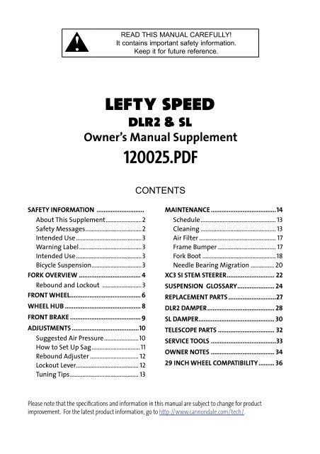
READ THIS MANUAL CAREFULLY!<br />
It contains important safety information.<br />
Keep it for future reference.<br />
lefty speed<br />
dlr2 & sl<br />
Owner’s <strong>Manual</strong> <strong>Supplement</strong><br />
120025.PDF<br />
CONTENTS<br />
SAFETY INFORMATION ...........................<br />
About This <strong>Supplement</strong> .......................2<br />
Safety Messages ....................................2<br />
Intended Use ..........................................3<br />
Warning Label ........................................3<br />
Intended Use ..........................................3<br />
Bicycle Suspension ................................3<br />
FORK OVERVIEW ................................... 4<br />
Rebound and Lockout .........................3<br />
FRONT WHEEL ........................................ 6<br />
WHEEL HUB ........................................... 8<br />
FRONT BRAKE ........................................ 9<br />
ADJUSTMENTS ......................................10<br />
Suggested Air Pressure ......................10<br />
How to Set Up Sag ...............................11<br />
Rebound Adjuster ............................... 12<br />
Lockout Lever ........................................ 12<br />
Tuning Tips ............................................ 13<br />
MAINTENANCE .....................................14<br />
Schedule ................................................ 13<br />
Cleaning ................................................ 13<br />
Air Filter ................................................. 17<br />
Frame Bumper ..................................... 17<br />
Fork Boot ............................................... 18<br />
Needle Bearing Migration ............... 20<br />
XC3 SI STEM STEERER ........................... 22<br />
SUSPENSION GLOSSARY ..................... 24<br />
REPLACEMENT PARTS ...........................27<br />
DLR2 DAMPER ...................................... 28<br />
SL DAMPER ........................................... 30<br />
TELESCOPE PARTS ................................ 32<br />
SERVICE TOOLS .....................................33<br />
OWNER NOTES .................................... 34<br />
29 INCH WHEEL COMPATIBILITY ......... 36<br />
Please note that the specifications and information in this manual are subject to change for product<br />
improvement. For the latest product information, go to http://www.cannondale.com/tech/.
About This <strong>Supplement</strong><br />
Cannondale Owner’s <strong>Manual</strong> <strong>Supplement</strong>s<br />
provide important model specific safety,<br />
maintenance, and technical information.<br />
They are not replacements for your<br />
Cannondale Bicycle Owner’s <strong>Manual</strong>.<br />
This supplement may be one of several for<br />
your bike. Be sure to obtain and read all of<br />
them.<br />
If you need a manual or supplement, or have<br />
a question about your bike, please contact<br />
your Cannondale Dealer immediately, or call<br />
us at one of the telephone numbers listed<br />
on the back cover of this manual.<br />
You can download Adobe Acrobat PDF<br />
versions of any Cannondale Owner’s<br />
<strong>Manual</strong>s or <strong>Supplement</strong>s from our website:<br />
http://www.cannondale.com/bikes/tech.<br />
• This manual is not a comprehensive<br />
safety or service manual for your bike.<br />
• This manual does not include assembly<br />
instructions for your bike.<br />
• All Cannondale bikes must be<br />
completely assembled and inspected<br />
for proper operation by a Cannondale<br />
Dealer before delivery to the owner.<br />
Safety Messages<br />
In this manual, information which affects<br />
your safety is emphasized in the following<br />
ways:<br />
WARNING<br />
A WARNING indicates a potentially<br />
hazardous situation which, if not<br />
avoided, can result in serious injury or<br />
death.<br />
CAUTION<br />
A CAUTION Indicates a potentially<br />
hazardous situation which, if not<br />
avoided, can result in serious damage<br />
to the product. The matters described<br />
under CAUTION may, if not avoided,<br />
lead to personal injury, or results<br />
depending on the situation and<br />
degree of damage. Important matters<br />
are described in CAUTION (as well as<br />
WARNING), so be sure to observe them.<br />
A NOTE provides helpful information or tips<br />
intended to make the information presented<br />
clearer.<br />
WARNING<br />
This document may include procedures<br />
beyond the scope of general mechanical<br />
aptitude.<br />
Special tools, skills, and knowledge may<br />
be required. Improper mechanical work<br />
increases the risk of an accident. Any<br />
bicycle accident has risk of serious injury,<br />
paralysis or death. To minimize risk<br />
we strongly recommend that owners<br />
always have mechanical work done by an<br />
authorized Cannondale retailer.<br />
2
120025.PDF<br />
Intended Use<br />
INTENDED for cross-country riding<br />
and racing which ranges from mild to<br />
agressive over intermediate terrain<br />
(e.g., hilly with small obstacles like<br />
roots, rocks, loose surfaces and hard<br />
pack and depressions). In XC riding,<br />
there are no large “sick drop” or drop<br />
offs, jumps or launches (wooden<br />
structures, dirt embankments) requiring<br />
long suspension travel or heavy duty<br />
components. Cross-country forks are<br />
light-weight, favoring nimble speed<br />
over brute force. Suspension travel is<br />
relatively short since the bike is intended<br />
to move quickly on the ground and not<br />
spend time in the air landing hard and<br />
hammering through things.<br />
NOT INTENDED for use in extreme forms<br />
of jumping/riding such as hardcore<br />
mountain, <strong>Free</strong>riding, Downhill, North<br />
Shore, Dirt Jumping, Hucking etc.<br />
WARNING<br />
USING YOUR LEFTY IMPROPERLY IS<br />
HAZARDOUS.<br />
Warning Label<br />
Located on the lower leg of the Lefty. Do<br />
not remove it. If it is missing or damaged,<br />
you can obtain a free replacement from<br />
Cannondale.<br />
Bike Suspension And<br />
Your Skills And Abilities<br />
WARNING<br />
YOU COULD HAVE A BAD ACCIDENT IF<br />
YOUR SKILL IS NOT UP TO HANDLING A<br />
SUSPENSION SYSTEM.<br />
Suspension systems (front fork, rear<br />
shocks) can increase the handling and<br />
stability of most bicycles. If you lack the<br />
skills and experience necessary to ride<br />
at higher speeds and maneuver over<br />
difficult terrain at the greatly increased<br />
performance level, you can ride faster<br />
than your abilities. You can lose control<br />
of the bike in these conditions and crash.<br />
Anytime you lose control of the bike,<br />
especially at high speed and in advanced<br />
terrain, you risk severe injury or death in<br />
a crash.<br />
• Ride at reduced speeds.<br />
• Learn the performance characteristics<br />
of your bike and suspension components<br />
before trying any downhill or very fast<br />
biking.<br />
•Ride within your skills and abilities.<br />
•Take a bicycle training course.<br />
3
fork overview<br />
dlr2 and dlr sl<br />
1 Steerer Tube<br />
2 Lockout Lever<br />
3 Rebound Knob<br />
4 Outer Collar<br />
5 Upper Clamp<br />
6 Outer Tube<br />
7 Bumper<br />
8 Lower Clamp<br />
9 Cable Guide<br />
10 Zip Tie<br />
11 Boot<br />
12 Spindle<br />
13 Brake Mounts (6” IS Standard)<br />
14 Air Filter Assembly<br />
15 Clamp Bolts<br />
16 WARNING Label<br />
<br />
<br />
<br />
<br />
<br />
<br />
<br />
<br />
<br />
<br />
<br />
<br />
<br />
<br />
<br />
<br />
<br />
<br />
<br />
4
120025.PDF<br />
dlr2 and dlr sl rebound & lockout assembly<br />
1.5mm<br />
2.0 N•m<br />
18.0 In•Lbs<br />
(3)<br />
(4)<br />
GR<br />
(1)<br />
(2)<br />
10mm<br />
5.0 N•m, 44.0 In•Lbs<br />
(5)<br />
GR<br />
(6)<br />
Use a Shimano<br />
TL-FC32 Crank<br />
Adapter Installation<br />
Tool (Shimano Y-130<br />
09210) to remove<br />
and install.<br />
GR<br />
(9) “TOP”<br />
(7)<br />
(8)<br />
(10)<br />
CAUTION: DO NOT LOOSEN<br />
OR TIGHTEN THIS NUT!!!<br />
GR<br />
(9)<br />
“TOP”<br />
1 Rebound Knob<br />
2 O-Ring (lubricate)<br />
3 Set Screw<br />
4 Lockout Lever Nut<br />
5 Lockout Lever<br />
6 O-Ring (lubricate)<br />
7 Outer Collar<br />
8 Washer<br />
9 Split Ring<br />
10 Nut<br />
GR - Apply bicycle bearing grease<br />
5
front wheel<br />
REMOVAL<br />
1. Place bike in a work stand with front<br />
wheel off the ground.<br />
2. Loosen the brake caliper mounting bolts.<br />
Note brake alignment shims between<br />
Lefty brake bosses and the caliper.<br />
4. Turn hub bolt (1) counter-clockwise to<br />
remove the hub from the spindle.<br />
NOTE: As the bolt is turned counterclockwise,<br />
it will begin to back against the<br />
hub cap bolt (2) causing the hub (3) to<br />
be drawn out and off the spindle bearing<br />
seats. Since the hub bolt is actually retained<br />
inside the hub body by the hub cap, the bolt<br />
will remain in the hub when the wheel is<br />
removed. There is no need to remove that<br />
cap from the hub. See the exploded view on<br />
page 8.<br />
CAUTION<br />
Make sure the axle bolt is completely<br />
loose before attempting to remove the<br />
wheel from the spindle.<br />
3 Tilt the lower caliper bolt out of the boss<br />
so the caliper is up out of the way of the<br />
disc. Snug up on the upper bolt to hold<br />
caliper in place.<br />
3<br />
2<br />
1<br />
5. Carefully slide the wheel off of the<br />
spindle carefully.<br />
6
120025.PDF<br />
CAUTION<br />
1. Cover the opening of a removed hub/<br />
wheel with a clean towel to prevent<br />
contamination.<br />
2. Protect spindle when wheel removed.<br />
A fall or drop to the ground can<br />
destroy or damage the spindle.<br />
INSTALLATION<br />
1. Inspect the inside of the wheel hub for<br />
contamination and and the condition<br />
of the hub seal. Take corrective action if<br />
necessary.<br />
Wipe all parts clean with a dry shop<br />
towel and apply a high-quality bike<br />
grease to:<br />
I.D. of the larger hub cartridge bearing .<br />
Both spindle bearing lands .<br />
Spindle axle bolt threads.<br />
WARNING<br />
Do not contaminate brake caliper, pads,<br />
or rotor with grease.<br />
spindle so, the larger hub bearing starts<br />
to position on it spindle seat. At this<br />
point, the axle bolt threads can correctly<br />
engage the threaded spindle if the<br />
wheel is held on straight.<br />
NOTE:<br />
Install the front wheel by positioning the<br />
bike horizontally with the spindle facing<br />
up. Then place the hub straight down<br />
onto the spindle, and tighten the axle<br />
bolt.<br />
3. When the axle bolt threads engage<br />
the spindle, turn the bolt clockwise<br />
with finger force slowly to allow the<br />
hub bearings to slide onto the spindle<br />
bearing seats.<br />
Once the hub has been drawn onto the<br />
hub completely, and proper threading is<br />
evident, use torque wrench to tighten<br />
to final 15.0 N•m (133.0 In•Lbs).<br />
4. Reinstall the brake caliper. Tighten bolts<br />
to 78.0 In•Lbf (9.0 N•m.)<br />
CAUTION<br />
LOCATE DISC BETWEEN THE PADS.<br />
Replace shims that are in use, be sure<br />
the shims are positioned between the<br />
caliper (adapter if any) and inner face of<br />
the fork mounts not under the head of<br />
the caliper bolts.<br />
USE ONLY 16 MM (Cannondale kit #<br />
LEFTYBOLTS. Longer bolts can result in<br />
contact with the brake rotor causing<br />
severe damage. Check clearance<br />
between the bolt tips and rotor after<br />
remounting the caliper.<br />
5. Spin the wheel to make sure it spins<br />
freely. Be sure to test the brakes for<br />
proper operation before riding.<br />
2. <strong>Sl</strong>ide the wheel straight onto the<br />
7
Loctite # 262<br />
6.2 N•m, 55.0 In•Lbs<br />
10<br />
GR<br />
GR<br />
GR<br />
NO RIDE<br />
9<br />
8<br />
7<br />
15.0 N•m, 133.0 In•Lbs<br />
4 5 6<br />
3<br />
GR<br />
GR<br />
QCTL108/<br />
,<br />
wheel hub<br />
11<br />
1 Extraction Cap<br />
2 Plastic Washer<br />
3 O-Ring (lubricate)<br />
4 Axle Bolt - 5mm Allen<br />
5 Outer hub bearing<br />
6 Hub<br />
7 Inner hub bearing<br />
8 Seal<br />
9 Brake disc<br />
10 Brake disc bolts<br />
11 Wheel Truing Tool<br />
Apply a high-quality bicycle bearing<br />
grease to areas indicated “GR.”<br />
LEFT-HAND<br />
THREADED<br />
Loctite # 242<br />
Park SPA-1<br />
1<br />
2<br />
8
120025.PDF<br />
front brake<br />
WARNING<br />
DO NOT RIDE WITHOUT A PROPERLY<br />
MOUNTED, ADJUSTED, AND<br />
FUNCTIONING FRONT BRAKE SYSTEM.<br />
Why? In addition to providing speed<br />
control, the front brake system on your<br />
Lefty (disc/caliper) acts as an integral<br />
secondary wheel retention system. If the<br />
system is missing or improperly installed,<br />
or if the wheel hub axle bolt should<br />
loosen, the front wheel could slide off<br />
the spindle end.<br />
When mounting IS compatible brake<br />
systems:<br />
Follow manufacturer’s instructions<br />
when mounting the brake caliper to the<br />
spindle brake bosses. Do not modify<br />
the fork in any way.<br />
PLEASE ASK YOUR CANNONDALE<br />
DEALER FOR HELP WHEN INSTALLING<br />
COMPATIBLE FRONT BRAKE SYSTEMS.<br />
Mount the front brake caliper using the 16<br />
mm bolts of Cannondale kit LEFTYBOLTS.<br />
See next figure.<br />
This photo shows the area where<br />
incorrect bolts will interfere with disc<br />
rotation possibly causing severe damage.<br />
Correct bolts are shown above.<br />
In addition to checking to make sure<br />
the bolt ends do not protrude, you must<br />
ensure proper thread engagement.<br />
Make sure the brake disc can not make<br />
contact with the fork boot. A rotating brake<br />
disc can wear through the boot allowing<br />
contaminants into the fork.<br />
16mm<br />
9
adjustments<br />
Suggested Air Pressure<br />
To set pressure, remove the valve cap at the bottom of the fork. Set the pressure according<br />
to rider weight. Use a bicycle suspension pump. Consult the table below. Stay within the<br />
pressure limits.<br />
At the bottom of the fork:<br />
Pressure Limits<br />
MIN. - 50 psi<br />
MAX. - 225 psi<br />
CAUTION<br />
Clean the valve and pump end<br />
before attaching a pump. Pumping<br />
in dirt can quickly ruin the fork. Stay<br />
within the pressure limits<br />
SCHRADER<br />
VALVE<br />
VALVE CAP<br />
NEG.<br />
SPRG.<br />
CARBON SL<br />
DLR2<br />
RIDER WT. (lbs) RUSH SCALPEL RUSH SCALPEL<br />
120 80 85 85 90<br />
130 85 90 90 95<br />
140 90 95 100 105<br />
150 100 105 105 110<br />
160 105 110 110 115<br />
170 110 115 120 125<br />
180 120 125 125 130<br />
190 125 130 135 140<br />
200 130 135 140 145<br />
210 135 140 145 150<br />
220 145 150 155 160<br />
This table lists approximate air pressure values. It is important after setting the air pressure to<br />
add or release pressure to set the sag. See next page<br />
10
120025.PDF<br />
How To Setup Sag<br />
1. Set air pressure according to rider weight.<br />
2. With the help of a second person, seat the<br />
rider on the<br />
saddle with feet on pedals and hands on<br />
the handlebar<br />
Measure distance X.<br />
3. To find Sag calculate:<br />
656mm - X = Sag(mm)<br />
X<br />
XC 20-30% 22-33mm<br />
TR 25-35% 27-38mm<br />
Add air to decrease sag.<br />
Release air to increase sag.<br />
Special Note:<br />
The damping cartridge negative spring of both Lefty DLR2 and CARBON SL forks is specific to the rider weight. See<br />
table below. If you find that you set the air pressure much higher or lower than suggested, we recommend the<br />
corresponding negative spring for best performance. Ask your Cannondale Dealer about negative spring kits for<br />
your fork.<br />
RIDER WT. (Lbs) FORK SIZE BIKE SIZE NEG. SPRG COLOR<br />
CANNONDALE KIT<br />
CARBON SL DLR 2<br />
to 145 SOFT PT/SM GREEN KT025/GRN KF200/GRN<br />
145-175 STANDARD MD BLUE KT025/BLU KF200/BLU<br />
175-195 FIRM LG RED KT025/RED KF200/RED<br />
195+ X-FIRM XL BLACK KT025/BLK KF200/BLK<br />
11
LOCKED<br />
1<br />
2<br />
UNLOCKED<br />
Rebound Adjuster - 1<br />
The red rebound adjuster at the top of the fork controls the speed at which the fork extends<br />
following compression.<br />
CARBON SL<br />
DLR2<br />
10 clicks 14 clicks<br />
To adjust rebound:<br />
Turn the adjuster clockwise in the direction marked "+" to increase the damping which<br />
slows the rebound speed.<br />
Turn the adjuster counter-lockwise in the direction marked "-" to decrease the damping<br />
which increases the rebound speed.<br />
Lockout Lever - 2<br />
The Lockout Lever turns fork travel "on" and "off." Be sure to rotate the lever completely to<br />
either position until it stops. Do not force the lever past the stops.<br />
FWD<br />
Lever Position<br />
LOCKED<br />
UNLOCKED<br />
Travel “off" - Fork locked in fully extended position.<br />
Travel "on" - Fork is unlocked and travel is active<br />
12
120025.PDF<br />
Suspension Tuning Tips<br />
Condition:<br />
Not using full travel, feels harsh, poor<br />
cornering traction<br />
Bottoms out, soft throughout travel,<br />
excessive sag<br />
Possible Solutions:<br />
Lower air pressure; softer compression<br />
damping; lighter negative spring; damper<br />
revalve<br />
Increase air pressure or stiffer coil springs;<br />
firmer compression damping; revalve<br />
Harsh over large bumps, but good over<br />
small ones<br />
Softer compression damping; lower air<br />
pressure or softer coil springs; revalve<br />
Harsh over small bumps but uses full<br />
travel<br />
Fork dives under braking<br />
Harsh on repeated bumps, packs down,<br />
feels like less travel, poor traction in<br />
corners<br />
Rebounds too quickly after bumps, poor<br />
traction in corners<br />
Lower air pressure or softer coil springs;<br />
softer compression damping; reduce<br />
spring preload; decrease bump threshold;<br />
firmer negative spring; revalve<br />
ncrease air pressure or stiffer coil springs;<br />
firmer compression damping; increase<br />
SPV pressure; decrease SPV volume;<br />
revlave<br />
Faster rebound damping; increase air<br />
pressure or stiffer coil springs<br />
<strong>Sl</strong>ower rebound damping; lower air<br />
pressure or softer coil springs<br />
Fork tops out harshly<br />
Lower air pressure; slower rebound; firmer<br />
negative spring; bearing reset<br />
13
maintenance schedule<br />
Fork maintenance is important to your safety and longtime performance of the fork. The<br />
following table is intended as a guide to establishing a schedule appropriate to your riding<br />
style and conditions.<br />
WHAT TO DO?<br />
Clean fork and visually inspect for damage. Check the fork<br />
externally for any sign of damage (e.g., bent fork, cracks, fluid<br />
leaks, tears, deep scratches, loose parts).<br />
Check and adjust air pressure.<br />
NORMAL<br />
(In Hours)<br />
RACE<br />
Check the fork function. Make sure it operates normally and<br />
all adjustments are normal. See Fork Problems next page<br />
BEFORE AND AFTER EVERY RIDE<br />
Inspect the fork boot. Check damage (e.g., cuts, holes, rips, rub<br />
marks, and loose attachment).<br />
Check tightening torque of the fasteners and bolts listed in<br />
Tightening Torques in this manual.<br />
Grease telescope. 50 25<br />
Needle bearing reset* 25 25<br />
Clean air filter 25 10<br />
Damping cartridge oil and seal change* 100 25<br />
Inspect, Replace Bumper<br />
PROFESSIONAL SERVICE*<br />
Annually, or when problems are indicated you must have<br />
your Lefty fork serviced through a Cannondale Dealer or an<br />
Authorized Headshok Service Center. Your fork should be<br />
disassembled by a suspension professional and evaluated for<br />
interal and external part wear and damaged parts replaced<br />
with new ones. It should also include any work described in<br />
technical bulletins or product recalls.<br />
AS NEEDED<br />
ANNUAL (Minimum)<br />
Our “Factory Tech Room,” (in the USA) provides professional services through Cannondale<br />
dealers for Headshok suspension forks . Please ask your dealer about the service programs<br />
available for your model fork.<br />
14
120025.PDF<br />
FORK PROBLEMS<br />
The following are conditions that can indicate a serious fork problem: If you find<br />
one, don’t ride the fork. Have the fork inspected by your Cannondale Dealer and any<br />
problems corrected first.`<br />
1. Any unusual “klunking” or knocking noises<br />
2. A change in fork travel.<br />
3. An over-extended or compressed boot<br />
4. Changes in the way the fork has been working<br />
5. Loss of adjustments features, air or oil loss.<br />
6. Crash or impact damage (deep scratches, gouges, dents, or bending).<br />
WARNING<br />
DO NOT RIDE ON A DAMAGED FORK. Stop riding a damaged fork immediately.<br />
YOU CAN BE SEVERELY INJURED, PARALYZED OR KILLED RIDING ON A BROKEN OR<br />
POORLY MAINTAINED FORK. Please ask your Cannondale Dealer to help you develop a<br />
complete maintenance program. Frequent checks are necessary to identify the problems<br />
that can lead to an accident.<br />
Cleaning<br />
USE ONLY A MILD SOAP AND WATER SOLUTION. Clean water and a common dish washing<br />
liquid will work best.<br />
COVER SENSITIVE AREAS WITH A CLEAN PLASTIC BAG. Secured temporarily with a rubber<br />
band or masking tape, a bag can prevent water damage to various bike components<br />
(bearings, seals, fork / shock adjustment features).<br />
SPRAY OFF BEFORE WIPING. To preserve the appearance of paint, finish, and decals, use a<br />
low pressure water hose to first spray off heavy soils and dirt.<br />
CAUTION<br />
DO NOT POWER WASH OR SPRAY WATER UNDER HIGH PRESSURE TO CLEAN. Power<br />
washing will force contaminants into parts where they will promote corrosion,<br />
immediately damage, or result in accelerated wear.<br />
DO NOT USE COMPRESSED AIR TO DRY.<br />
DO NOT USE ABRASIVE OR HARSH CHEMICAL CLEANER/SOLVENTS which can damage<br />
the finish or attack and destroy both the outside and internal parts.<br />
When rinsing, avoid directing the spray directly at shock/fork adjusters or bearings.<br />
15
IMPORTANT INFORMATION ABOUT RIDING IN WET, VERY<br />
HUMID, OR COASTAL CONDITIONS<br />
The Cannondale Headshok needle bearing system uses precise components such as<br />
bearings and races that are made of high strength steel. These components require<br />
proper maintenance before and after riding in severely wet conditions.<br />
PRE-RIDE CHECKS<br />
The following service and checks are<br />
recommended above and beyond typical<br />
scheduled maintenance if riding in<br />
severely wet conditions.<br />
1. Inspect fork boot for rips and tears.<br />
2. Inspect and renew grease under fork<br />
boot.<br />
3. Clean, dry, and oil breather filter<br />
element.<br />
4. Ensure zip-ties and band clamps<br />
are properly tightened (replace as<br />
needed)<br />
POST-RIDE CHECKS<br />
The following service and checks are<br />
recommended above and beyond typical<br />
scheduled maintenance after riding in<br />
severely wet conditions.<br />
1. Inspect and renew grease under fork<br />
boot – wipe dry if water is present.<br />
2. Inspect fork boot for rips and tears if<br />
water is present in boot.<br />
3. Clean, dry, and oil breather filter<br />
element.<br />
4. Ensure zip-ties and band clamps<br />
are properly tightened (replace as<br />
needed).<br />
ZIP TIE<br />
AIR FILTER<br />
COVER<br />
CLAMP<br />
ZIP TIE<br />
BOOT<br />
ZIP TIE<br />
IF THE FORK BECOMES SUBMERGED,<br />
PERFORM THE CHECKS IMMEDIATELY.<br />
16
120025.PDF<br />
Air Filter<br />
The air filter assembly is located over two<br />
holes in the outer tube. Air passes in and<br />
out of the ports as the fork moves.<br />
The air filter assembly stops the passage<br />
of dirt and water which would damage the<br />
internal fork components.<br />
The small holes (a) at the base of the air<br />
filter cover should remain open.<br />
The foam filter element (1) should be<br />
cleaned and re-oiled frequently.<br />
The small holes at the base of the filter<br />
cover should be positioned to the sides<br />
of the and not to the front or back of the<br />
bicycle to minimize the chance dirt thrown<br />
by the wheels will plug the holes.<br />
Clean the foam air filter element with<br />
warm soapy water, allow to dry completely,<br />
and reapply a high-quality foam air filter oil<br />
before reinstallation. Be sure to massage<br />
the oil into the foam. A foam element<br />
without the oil is ineffective.<br />
Use air filter<br />
oil foam.<br />
AIR<br />
HOLES<br />
FOAM ELEMENT<br />
COVER<br />
AIR<br />
HOLES<br />
Frame Bumper<br />
The frame bumper (1) located on the outer<br />
tube (2) between the clamp cushions the<br />
frame from contact with the fork. Replace<br />
it with a new one if it ever becomes<br />
damaged, torn, or missing.<br />
2<br />
1<br />
17
Fork Boot<br />
The fork boot protects the internal parts<br />
(inner tube, races, lubricant, needle bearings,<br />
and other internal parts) from contamination<br />
and damage. It is a barrier to water, dirt,<br />
dust, mud, or grit encountered while riding.<br />
If the boot is loose or damaged; dirt, water,<br />
dust, salt spray or other contaminants will<br />
quickly ruin the fork.<br />
Always tighten the zip ties and clamps<br />
securely. Replacement boots, zip<br />
ties, and cable clamps are available<br />
through a Cannondale Dealer.<br />
If you find boot damage, the area under<br />
the boot should be professionally<br />
inspected for contamination or damage.<br />
The damaged boot must be replaced<br />
with a new one. Do not try to fix it.<br />
WARNING<br />
A<br />
CHECK THE BOOT BEFORE EACH RIDE.<br />
DON’T RIDE IF IT IS DAMAGED.<br />
REPLACE IT WHEN YOU FIND DAMAGE.<br />
Checks<br />
1. Check the boot for damage, cracking,<br />
splits, or tears. Be sure to check in<br />
the folds of the boot. Check for any<br />
cables or lines rubbing the boot.<br />
2. Check the attachment of the boot<br />
at the top and bottom. The upper<br />
and lower boot lips should be fitted<br />
over the lower collar and fork lip.<br />
NO PART OF THE FORK INNER TUBE<br />
(lower leg) SHOULD BE EXPOSED.<br />
3. Replace the zip ties and band clamps .<br />
Cleaning and Re-greasing The<br />
Telescope Under the Boot<br />
The fork inner tube and inner bearing races,<br />
parts of the telescopic fork assembly are<br />
located behind the fork boot.<br />
Wiping off old grease with a dry shop towel<br />
and re-apply a fresh heavy coating of grease<br />
helps assure that ,races and needle bearings<br />
remain well lubricated.<br />
Any clean high-quality bicycle bearing<br />
grease selected for riding temperatures and<br />
environment can be used. We assemble<br />
forks at our factory using Royal Purple Ultra<br />
Performance Grease NLGI #2 (ISO 46 BASE).<br />
1. Remove the front wheel.<br />
2. Release all fork air pressure.<br />
3. Carefully cut the upper and lower zip<br />
ties securing the fork boot. Some forks<br />
may have an screw type band clamp<br />
securing the upper portion of the boot.<br />
If this is the case, loosen the clamp.<br />
4. Lift the unsecured boot up to<br />
expose the inner tube (1).<br />
18
120025.PDF<br />
5. Wipe away any old grease with<br />
a clean lint-free shop towel.<br />
Cycle the fork and repeat.<br />
CAUTION<br />
Do not use solvents or spray chemicals<br />
to clean. Protect the exposed fork from<br />
contaminants. Work in a clean area.<br />
6. Visually inspect the inner tube (1)<br />
and inner races (2) a for any signs of<br />
corrosion or damage. Some very light<br />
wear to the inner races is normal,<br />
however, they are worn-out if any<br />
scratches or grooves are evident. If<br />
heavy corrosion is present they must be<br />
replaced. If ridges can be felt by the tip<br />
of a rolling ball point pen over the race,<br />
the races should be replaced. If damage<br />
is found, the damaged parts must be<br />
replaced new before the fork is ridden.<br />
the fork and carefully re-apply grease.<br />
Cycling moves the new grease inside<br />
the fork onto the outer tube races<br />
and bearing cages. Its OK to leave<br />
a good coating under the boot.<br />
Avoid applying grease to the area<br />
(A) just under the boot/zip tie.<br />
Also, do not contaminate the<br />
brake disc with grease.<br />
Wipe it off the inner tube and inner<br />
boot to ensure that boot does not<br />
slide up when zip tie is re secured.<br />
2<br />
A<br />
1<br />
7. When you are finished, inspect the<br />
condition of the boot. Make sure it is<br />
undamaged. Replace it if it is. Re secure<br />
the boot and reassembly the fork.<br />
WARNING<br />
7. Use a stiff nylon brush to apply a<br />
high-quality bicycle grease onto the<br />
inner tube and bearing races. Cycle<br />
NEVER RIDE YOUR LEFTY IF THE INNER<br />
TUBE, BEARING RACES, OR BEARINGS<br />
ARE CORRODED, RUSTED, OR CRACKS<br />
ARE PRESENT.<br />
19
Needle Bearing<br />
Migration Reset<br />
NOTE: Ideally, reset the bearings after 25<br />
hours of normal riding or 10 hours of hard<br />
riding/racing to maintain optimum fork<br />
performance.<br />
We recommend that the needle bearing<br />
reset procedure should be performed by a<br />
professional mechanic.<br />
Explanation<br />
Inside the fork the four needle bearing<br />
cages (1) move independently up and down<br />
between each inner (2) and outer race pair<br />
(3). This bearing arrangement provides<br />
numerous advantages to fork performance<br />
but requires simple periodic maintenance to<br />
ensure proper alignment.<br />
Evidence of migration is:<br />
1 An unusual "top out" noise .If<br />
an unusual noise is heard, the<br />
extended fork length should be<br />
measured to confirm the condition.<br />
2. The fork’s maximum extended<br />
length is reduced.<br />
If migration re-occurs frequently<br />
(immediately after resetting), the cause<br />
could be damage present in the inner or<br />
outer races, ,bearings/cages or other fork<br />
parts. Inspection and replacement of<br />
damage parts will be required to correct a<br />
persistent problem with bearing migration.<br />
2 3<br />
1<br />
ALIGNED<br />
MIGRATED<br />
Bearing Migration<br />
If a cage or cages shifts out of alignment up<br />
or down in relation to the others it is said to<br />
have “migrated.” This migrated condition<br />
will limit travel.<br />
Needle bearing migration is normal and<br />
expected. However, if the fork is ridden in<br />
this state for extended periods, the fork can<br />
be damaged.<br />
20
120025.PDF<br />
Resetting Migrated Needle Bearings<br />
1. Place the bike in a work stand.<br />
Release all the air pressure<br />
through the Schrader valve.<br />
2. Remove the rebound knob and<br />
lockout lever. Remove the outer<br />
cap with the Shimano bottom<br />
bracket tool TL-FC32. See page 5.<br />
3. Compress the telescope and remove<br />
the two split rings from the top cap..<br />
4. Fully extend the fork, and measure from<br />
top edge of outer tube to bottom edge<br />
of spindle. See right. If the length is<br />
out of specification do the following:<br />
695 ±5mm<br />
Firmly extend the telescope until it<br />
stops (tip - listen for the knocking at<br />
full extension to change from a hollow<br />
sound to a solid sound - this indicates<br />
full extension has been achieved). Do<br />
this several times using only moderate<br />
force, extend the lower fork leg using a<br />
pumping action.<br />
After, you have performed this<br />
action several times, re-measure.<br />
CAUTION<br />
If fork is out range following reset<br />
attempt, it may be damaged internally.<br />
The fork should be disassembled and<br />
inspected by a professional mechanic<br />
before it is ridden.<br />
The Rebound,Lockout Assembly and<br />
Split rings is removed.<br />
All air is released<br />
Telescope is extended fully.<br />
21
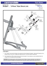
xc3 si stemsteerer<br />
Installation<br />
1. Make sure both the upper and lower<br />
Lefty clamp bolts are loose.<br />
2. Make sure the headset parts are<br />
assembled as shown (next page).<br />
3. Position the Lefty clamps onto the<br />
headtube as shown.<br />
4. Insert Cannondale specific tool KT020/<br />
through the bottom clamp, into the<br />
head tube, and out the upper clamp.<br />
5. Make sure the plastic ring (6) is on the<br />
stem. Insert the bottom of the stemsteerer<br />
onto the top of the tool.<br />
6. Remove the cap (1) from the top of the<br />
steerer. Use a rubber mallet to drive the<br />
stem-steerer into the head tube until it<br />
stops. Return the cap (1).<br />
7. Clean and apply grease to the steerer<br />
bolt threads and install into the bottom<br />
of the stem-steerer. Align handlebar<br />
and tighten the bolt to 9 N•m.<br />
8.. Tighten the upper and lower clamp bolts<br />
to 9 N•m.<br />
Removal<br />
1 Loosen upper and lower clamp bolts.<br />
2. Remove steerer bolt (10).<br />
3. Insert the small end of KT020/ into the<br />
bottom of the stem-steerer and drive<br />
the stem-steerer up out of the head<br />
tube.<br />
STEM<br />
STEERER<br />
TOOL<br />
KT020/<br />
APPLY<br />
GREASE<br />
TO<br />
THREADS<br />
OF<br />
BOLT<br />
22
120025.PDF<br />
SIZE<br />
LENGTH<br />
ANGLE<br />
H-BAR DIA.<br />
DATE<br />
(1)<br />
(4)<br />
6 N•m<br />
(5)<br />
(2)<br />
1 Cap<br />
2 O-Ring (lubricate)<br />
3 Stem<br />
4 Handlebar clamp<br />
5 Clamp boltsr<br />
6 Plastic ring<br />
7 Seal<br />
8 Upper Bearing<br />
9 Bearing cup<br />
10 Steerer bolt<br />
(3)<br />
(6)<br />
(7)<br />
(8)<br />
(9)<br />
9 N•m<br />
WARNING<br />
The steerer bolt (10) is a<br />
structural part and must<br />
be installed. Follow<br />
installation instructions.<br />
HEADTUBE<br />
Notes:<br />
1. Ensure that the plastic ring (6) is<br />
on the stem before inserting into<br />
head tube.<br />
2. When you tighten or loosen the<br />
steerer bolt (10), be sure to loosen<br />
the lower clamp bolt and insert<br />
the 5mm Allen key completely to<br />
avoid stripping the steerer bolt.<br />
3. The XC3 SI stem is only<br />
compatibile with Carbon and<br />
Bonded Alloy Lefties.<br />
(9)<br />
(8)<br />
9 N•m<br />
9 N•m<br />
(10)<br />
Keep the drain hole in (10) clear.<br />
9 N•m<br />
23
suspension<br />
glossary<br />
Damping - The process of dissipating energy<br />
and slowing down the suspension motion.<br />
Damping absorbs the force of a bump or<br />
landing. Damping is usually done with oil,<br />
but can be done with air and friction as well.<br />
Spring - The part of a suspension fork or<br />
shock that holds the rider/bike up. Springs<br />
can be metal coils (steel or titanium) or high<br />
pressure air.<br />
Compression - The process of squeezing<br />
together. The front and rear suspension<br />
compress when hitting a bump, landing off<br />
a jump, or braking for corners. Compression<br />
can refer to the spring or damping<br />
(compression damping).<br />
Rebound - The process of extending back<br />
from a compressed state. The front and rear<br />
suspension rebound after being compressed<br />
from a bump or jump landing. Rebound can<br />
refer to the spring or damping (rebound<br />
damping).<br />
Low Speed (compression or rebound) - Low<br />
speed damping references the speed at<br />
which the fork/damper travels through its<br />
stroke. It does NOT refer to the speed at which<br />
the rider is moving. Low speed bumps are<br />
typically round in shape or smooth actions<br />
like jump landings and pedal bob. In the<br />
case of rebound, it mostly refers to rebound<br />
speed caused by smaller bumps where the<br />
fork does not get fully compressed.<br />
High Speed (compression or rebound) -<br />
High speed damping references the speed<br />
at which the fork/damper travels through<br />
its stroke. It does NOT refer to the speed at<br />
which the rider is moving. High speed bumps<br />
are typically square in shape or harsh terrain<br />
like sharp-edged rocks that may cause pinch<br />
flats. In the case of rebound, it mostly refers<br />
to rebound speed caused by larger bumps<br />
where the fork gets fully compressed.<br />
24<br />
Bottom Out - When the front or rear<br />
suspension fully compresses to absorb a<br />
bump or jump landing. A hard stop is usually<br />
felt at bottom out.<br />
Top Out - When the front or rear suspension<br />
fully extends after absorbing a bump or jump<br />
landing. A soft stop is usually felt at top out.<br />
The fork and shock are typically topped out<br />
without a rider on the bike.<br />
Compression Adjuster - Used to adjust the<br />
front or rear compression damping setting.<br />
Rebound Adjuster - Used to adjust the front<br />
and rear rebound setting<br />
Sag - Refers to how much the front and rear<br />
suspension compress when a rider sits on<br />
the bike. Sag is measured as a percentage<br />
of suspension travel. Typical sag values are:<br />
20-30% for XC riding and 25-35% for Trail/<br />
<strong>Free</strong>ride.<br />
Preload - Refers to how much initial<br />
compression is applied to a spring. In the<br />
case of an air spring, preload is achieved by<br />
increasing the air pressure. You use preload<br />
to adjust the sag. More preload decreases<br />
the sag. Less preload increases the sag.<br />
Spring Rate - Refers to the strength of a<br />
spring. A spring with a higher rate is stiffer, a<br />
lower rate softer.<br />
Diving - When a suspension fork compresses<br />
and causes the pitch of the bicycle drop.<br />
Mostly occurs when braking.<br />
Revalve - Revalving is the process of changing<br />
the internal compression and rebound shims<br />
to change the flow of oil through passages in<br />
the forks and shock. A suspension specialist<br />
should revalve your bike’s suspension.
120025.PDF<br />
replacement parts (kits)<br />
ORDER<br />
LEFTY<br />
DLR2 DLR SL<br />
DESCRIPTION<br />
Upper Fork Parts<br />
KF210/ ● DLR2 Lockout lever w/retaining nut<br />
KF206/ ● Upper collar alloy telescope<br />
KF207/ ● Upper collar carbon telescope<br />
HD016/ ● ● Steerer tube carbon Lefty<br />
HD215/ ● ● Frame bumper<br />
QSMSEAL/ ● ● Upper Headshok bearing seal<br />
QHDST/EBO ● ● Headshok headset cups Qty 2, w/ Headshok bearing Qty 1<br />
HD169/ ● ● Headshok headset bearings Qty 2<br />
KF211/ ● ● Rebound knob with set screw and O-ring<br />
KF205/ ● ● Split rings Qty 2<br />
KT031/ ● Lockout lever w/retaqining nut<br />
KT027/ ● Upper collar<br />
Lower Fork Parts<br />
KF208/ ● Kit, Collar, Lower,Alloy<br />
KF209/ ● Kit, Collar, Lower,Carbon,clip+bushing<br />
KF212/ ● Schrader cap assembly (cap, O-ring, Schrader valve, valve cap)<br />
HD208/ ● Kit, Outer Race Clip-Lefty / 5<br />
QC681/ ● Upper fork clamp alloy<br />
QC682/ ● Lower fork clamp alloy<br />
KF257/ ● Inner Leg w/spindle DLR2<br />
HD175/BLK ● ● Kit, Zip Ties, Black / 50<br />
HD185/BLK ● ● Kit, Zip Ties, Double Head /10<br />
HD209/BLK ● ● Air filter assembly (filter element and cover)<br />
QC678/ ● ● Fork Boot<br />
HD210/ ● ● Steer tube upper plug<br />
KT029/ ● Inner Leg w/spindle DLR SL<br />
KT028/ ● Schrader cap assembly (cap, O-ring, Schrader valve, valve cap)<br />
KF209/ ● Lower collar, carbon telescope Clip+Bushing<br />
Headshok Service Tools<br />
KT020/ ● ● Steerer Installation/Remioval Tool “The Ernie” for installing steerers<br />
HDTL146/ ● ● Castle Tool for removing and installing damping cartridge into<br />
telescope<br />
HD187/ ● ● 1/2” Shaft clamp for clamping damping cartridge shaft<br />
HDTL168/ ● ● Bullet tool for installing oil caps into damping cartridge<br />
For an up to date list of kits available for your bike, please visit our<br />
Tech Center at : http://www.cannondale.com/tech/<br />
25
ORDER<br />
LEFTY<br />
DLR2 DLR SL<br />
DESCRIPTION<br />
Damping Cartridge Parts<br />
KF200/BLK ● Negative spring X-FIRM<br />
KF200/BLU ● Negative spring STANDARD<br />
KF200/GRN ● Negative Spring, SOFT<br />
KF200/RED ● Negative spring FIRM<br />
KF201/BLK ● Complete damping cartridge w/ X-FIRM negative spring<br />
KF201/BLU ● Complete damping cartridge w/ STANDARD negative spring<br />
KF201/GRN ● Complete damping cartridge w/ SOFT negative spring<br />
KF201/RED ● Complete damping cartridge w/ FIRM negative spring<br />
KF202/ ● Seal Kit DLR2<br />
KF204/ ● Revalving kit (shims) DLR2<br />
KF268/ ● DLR2 Damping cartridge oil cylinder w/ relief cut<br />
KF213/ ● ● Air piston<br />
HD226/ ● ● Damping cartridge oil, Golden Spectro 85/150 Qt.<br />
KF272/ ● ● Pressure compensator spring<br />
KT026/GRN ● Complete damping cartridge w/ SOFT negative spring<br />
KT026/BLU ● Complete damping cartridge w/ STANDARD negative spring<br />
KT026/RED ● Complete damping cartridge w/ FIRM negative spring<br />
KT026/BLK ● Complete damping cartridge w/ X-FIRM negative spring<br />
KT025/GRN ● Negative spring SOFT<br />
KT025/BLU ● Negative spring STANDARD<br />
KT025/RED ● Negative spring FIRM<br />
KT025/BLK ● Negative spring X-FIRM<br />
KT024/ ● Seal kit DLR SL<br />
KT030/ ● Revalving kit (shims) DLR SL<br />
Needle Bearings & Races<br />
HD161/ ● ● Needle Bearings Qty 4<br />
HDR2L/020 ● Kit, Race-Inner: 10.197”-259.0mmx.020-.51mm (4)<br />
HDR2L/021 ● Kit, Race-Inner: 10.197”-259.0mmx.021”-.53mm (4)<br />
HDR2L/022 ● Kit, Race-Inner: 10.197”-259.0mmx.022”-.56mm (4)<br />
HDR2L/023 ● Kit, Race-Inner: 10.197”-259.0mmx.023”-.58mm (4)<br />
HDR2L/024 ● Kit, Race-Inner: 10.197”-259.0mmx.024”-.61mm (4)<br />
HDR2L/025 ● Kit, Race-Inner: 10.197”-259.0mmx.025”-.635mm (4)<br />
HDR2N/024 ● Kit,Race-Outer:8.110”-206mmx.024”-.61mm (4)<br />
HDR1G/024 ● Kit,Race-Outer:7.480” x .024”<br />
HDR2P/020 ● Kit,Race-Inner:7.520” x .020”<br />
HDR2P/021 ● Kit,Race-Inner:7.520” x .021”<br />
HDR2P/022 ● Kit,Race-Inner:7.520” x .022”<br />
HDR2P/023 ● Kit,Race-Inner:7.520” x .023”<br />
HD208/ ● Kit,Outer Race Clip,5<br />
KF119/ ● Kit,Race Clip,Metric<br />
26
120025.PDF<br />
ORDER<br />
H-Bar dia.<br />
(mm)<br />
DESCRIPTION<br />
Stem<br />
Rise°<br />
Stem<br />
Length ( mm)<br />
XC3 Stem-Steerer QSD090-5318/BBQ 31.8 - 5 90 BBQ<br />
QSD100-5318/BBQ 31.8 - 5 100 BBQ<br />
QSD120-5318/BBQ 31.8 - 5 120 BBQ<br />
QSD09005318/BBQ 31.8 5 90 BBQ<br />
QSD10005318/BBQ 31.8 5 100 BBQ<br />
QSD12005318/BBQ 31.8 5 120 BBQ<br />
QSD09020318/BBQ 31.8 20 90 BBQ<br />
QSD10020318/BBQ 31.8 20 100 BBQ<br />
QSD12020318/BBQ 31.8 20 120 BBQ<br />
XC3 Stem QSC11020318/BBQ 31.8 20 110 BBQ<br />
QSC13020318/BBQ 31.8 20 130 BBQ<br />
QSC09020318/BBQ 31.8 20 90 BBQ<br />
QSC08005318/BBQ 31.8 5 80 BBQ<br />
QSC10005318/BBQ 31.8 5 100 BBQ<br />
QSC12005318/BBQ 31.8 5 120 BBQ<br />
QSC14005318/BBQ 31.8 5 140 BBQ<br />
QSC09005318/BBQ 31.8 5 90 BBQ<br />
QSC11005318/BBQ 31.8 5 110 BBQ<br />
QSC12020318/BBQ 31.8 20 120 BBQ<br />
QSC11020254/BBQ 25.4 0 110 BBQ<br />
QSC13020254/BBQ 25.4 0 130 BBQ<br />
QSC09020254/BBQ 25.4 0 90 BBQ<br />
QSC08005254/BBQ 25.4 5 80 BBQ<br />
QSC10005254/BBQ 25.4 5 100 BBQ<br />
QSC12005254/BBQ 25.4 5 120 BBQ<br />
QSC14005254/BBQ 25.4 5 140 BBQ<br />
QSC09005254/BBQ 25.4 5 90 BBQ<br />
QSC11005254/BBQ 25.4 5 110 BBQ<br />
QSC12020254/BBQ 25.4 5 120 BBQ<br />
Holey Stem QSC10035254/BBQ 25.4 35 100 BBQ<br />
QSC12035254/BBQ 25.4 35 120 BBQ<br />
QSC13035254/BBQ 25.4 35 130 BBQ<br />
QSC08035254/BBQ 25.4 35 80 BBQ<br />
Color<br />
27
dlr2 damper<br />
28
120025.PDF<br />
ASSEMBLY NOTES:<br />
1. NLGI 2 synthetic grease is to be applied to all seals, grooves,<br />
surfaces and glands.<br />
2. See size table for shim stack and topout spring specifications.<br />
TOPOUT SPRING<br />
29
sl damper<br />
ITEM QTY DESCRIPTION<br />
1 2 TOP OUT SPRING THRUST WASHER<br />
2 1 2-010 O-RING 6.07 ID X 1.78 W<br />
3 3 2-018 O-RING 18.77 ID X 1.78 W<br />
4 2 2-111 O-RING 10.77 ID X 2.62 W<br />
5 1 O-RING 2.00 ID X 1.00 W<br />
6 1 O-RING 3.00 ID X 1.00<br />
7 1 O-RING 9.00 ID X 1.00 W<br />
8 1 O-RING 9.00 ID X 1.00 W<br />
9 2 O-RING 8.00 ID X 1.50 W<br />
10 1 SFHS M2 5X4<br />
11 SEE COMPRESSION SHIM STACK CHART<br />
12 1 DETENT BALL M2<br />
13 1 113 QUAD RING 13.94 ID X 2.62 W<br />
14 2 OIL CAP<br />
15 1 LOCKOUT SHIM<br />
16 1 PRELOAD SHIM<br />
17 1 PRESSURE COMP PISTON<br />
18 1 PRESSURE COMP SPRING<br />
19 1 TOPOUT PERCH<br />
20 2 TOPOUT TOPHAT<br />
22 1 TOPOUT SPRING SPACER<br />
23 1 See Chart DLR NEG SPRING<br />
24 1 SHAFT PRELOAD NUT M75<br />
25 1 DLR UPPER SHAFT SL<br />
26 1 DLR TUNING SHAFT SL<br />
27 1 DLR TOPOUT BUMPER PERCH<br />
28 1 DLR THRUSHAFT SL<br />
29 1 DLR OUTER CAP SL<br />
30 1 DLR OIL CYLINDER SL<br />
31 1 DLR LOWER SHAFT SL<br />
32 1 DLR LOCKOUT PISTON SL<br />
33 1 LOCKOUT WASHER<br />
34 1 DLR 100 DETENT SPRING SL<br />
35 1 DLR QUAD CHECK UPPER SL<br />
36 1 DLR QUAD CHECK LOWER SL<br />
37 2 UCUP 5X75<br />
NEGATIVE SPRINGS<br />
SIZE COLOR RATE<br />
SOFT GREEN 6.4N/mm<br />
STANDARD BLUE 8.6N/mm<br />
FIRM RED 10.7N/mm<br />
X-FIRM BLACK 13.2N/mm<br />
30
120025.PDF<br />
Negative<br />
Spring<br />
COMPRESSION SHIM STACK ORDER<br />
1 2 3 4<br />
SIZE 12x14x.102 12x20.5x.102 12x16x.102 12x18x.102<br />
P/N 120171 119732 120053 120172<br />
Green Soft 2 1 1<br />
Blue Standard 2 1 1<br />
Red Firm 2 1 1<br />
Black X-Firm 2 1 1<br />
4 3 2 1<br />
PISTON<br />
31
telescope<br />
parts<br />
WARNING<br />
HIGH PRESSURE HAZARD<br />
– Do not attempt to service<br />
a pressurized fork. You can<br />
severely injured or killed<br />
by pressurized (forcefully)<br />
ejected fork parts. Release<br />
all air pressure before<br />
performing any work.<br />
ITEM QTY DESCRIPTION<br />
1 1 SCHRADER CAP<br />
2 1 SCHRADER CORE<br />
3 2 SPLIT LOCATING RING<br />
4 1 TOP CAP SEAL PLASTIC<br />
5 1 2-019 O-RING 20.35 ID X 1.78 W<br />
6 1 2-020 O-RING 21.95 ID X 1.78 W<br />
7 1 2-020 O-RING 21.95 ID X 1.78 W<br />
8 2 2-117 O-RING 20.29 ID X 2.62 W<br />
9 1 SHSS M3X3<br />
10 1 DLR 110 AIR PISTON<br />
11 1 DLR 110 LOCKOUT KNOB<br />
12 1 DLR 110 REBOUND KNOB<br />
13 1 DLR 110 SHAFT PRELOAD NUT M75<br />
14 1 07 DLR 110 DAMPER<br />
15 1 07 CARBON LEFTY TELESCOPE<br />
16 1 07 UPPER COLLAR CARBON<br />
17 1 07 DLR 110 SCHRADER CAP<br />
18 1 07 DLR 110 AIR PISTON SPACER<br />
32
120025.PDF<br />
cannondale<br />
service tools<br />
HDTL146/ - Castle Tool<br />
HD187/ - 1/2 in Shaft Clamps<br />
HDTL168/ - Bullet Tool<br />
33
owner notes<br />
Record maintenance history, service, or set up information .<br />
DATE<br />
WORK PERFORMED<br />
34
35<br />
120025.PDF
29 inch wheel compatibility<br />
Travel reduction parts are factory installed into Lefties adapted for use with 29” inch<br />
wheels. The travel reduction parts limit the travel to 80mm. Lefties that have travel<br />
reduction parts installed are identified with the compatibility label illustrated below left.<br />
Travel reduction parts limit telescope travel necessary to prevent wheel interference with<br />
the frame. See below right.<br />
THIS IS THE<br />
29” WHEEL<br />
COMPATIBILITY<br />
LABEL<br />
WHEEL-TO-TIRE<br />
CLEARANCE AREA.<br />
WARNING<br />
LEFTY 80MM TRAVEL REDUCTION IS REQUIRED TO MAINTAIN THE WHEEL-TO-FRAME<br />
CLEARANCE NEEDED FOR 29 INCH WHEELS. Lefties with travel reduction factory<br />
installed are indentifed with a compatibilty label on the lower fork. If the frame<br />
contacts the rotating wheel while riding, the tire can be stopped suddenly. This can<br />
throw you off the bicycle or cause you to loose control and crash.<br />
Do not install a 110mm travel lefty onto a bicycle frame designed for 29 inch wheels. If<br />
you have any questions, please ask your Cannondale Dealer for help.<br />
YOU CAN BE SEVERELY INJURED, PARALYZED OR KILLED IN AN ACCIDENT<br />
IF YOU IGNORE THIS WARNING.<br />
36