500 - U5 (CF500-3) - Technical Service Manual.pdf - Mojo
500 - U5 (CF500-3) - Technical Service Manual.pdf - Mojo
500 - U5 (CF500-3) - Technical Service Manual.pdf - Mojo

You also want an ePaper? Increase the reach of your titles
YUMPU automatically turns print PDFs into web optimized ePapers that Google loves.
CF<strong>500</strong>-3/UTV<br />
WWW.CFMOTO.COM
FOREWORD<br />
This manual contains an introductory description<br />
of procedures for inspection maintenance,<br />
overhauldisassembly & assemblyremoval and<br />
installation of components and parts,<br />
troubleshooting and service data together with<br />
illustrations of our UTV Model CF<strong>500</strong>-3.<br />
Chapter 1general service information, tools<br />
vehicle structure and technical data.<br />
Chapter3: key points for inspection and<br />
adjustingservice guide.<br />
Chapter 2 and after Chapter 3disassembly of<br />
parts and componentsinstallationoverhaul and<br />
troubleshooting.<br />
The manufacturer reserves the right to make<br />
improvements or modifications to the<br />
products without prior notice. Overhaul and<br />
maintenance should be done according to<br />
the actual state and condition of the UTV.<br />
INDEX<br />
Vehicle<br />
<strong>Service</strong> Information 1<br />
Vehicle Body,Muffler 2<br />
Inspection & Adjustment 3<br />
Cooling System 4<br />
Removal and Installation of Engine 5<br />
Removal, Inspection and Assemble of 6<br />
Engine<br />
Carburetor 7<br />
Front Wheel, Front Brake, Suspension, 8<br />
Steering<br />
Rear Wheel, Rear Brake, Suspension 9<br />
Front and Rear Axle 10<br />
Battery, Charging System 11<br />
Ignition System 12<br />
Lighting, Dashboard & Switches 13<br />
Circuit DiagramWiring Diagram 14<br />
Troubleshooting 15
Conversion Table<br />
Item Example Conversion<br />
Pressure 200Kpa (2.00kgf/cm 2 )<br />
33kpa(250mmHg)<br />
1kgf/cm 2 =98.0665kpa 1kpa=1000pa<br />
1mmHg=133.322Pa=0.133322Kps<br />
Torque 18Nm(1.8kgf-m) 1kgf m=9.80665Nm<br />
Volume 419ml 1ml=1cm 3 =1cc<br />
1l=1000cm 3<br />
Force 12N (1.2kgf) 1kgf=9.80665N
Cautions<br />
Safety Cautions<br />
0DLQWHQDQFH ,QIRUPDWLRQ<br />
Cautions……………………………1-1<br />
Tightening Torque………………1-13<br />
VIN Number & Engine Number……1-3<br />
Lubricant, Sealing Agent…………1-18<br />
Main Data Table……………………1-4<br />
Cable Routing……………………1-19<br />
Overhaul Data Table………………1-6<br />
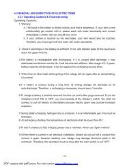
1. Hazardous components in exhaust. Do not run the engine in a enclosed or poorly ventilated<br />
place for long time.<br />
<br />
2. Do not touch the engine or muffler with bare hands after the engine has just stopped to<br />
avoid scalding. Wear long-sleeve work clothes and gloves for operation.<br />
3.Battery liquid (dilute sulfuric acid) is highly caustic and may cause burns to skin and eyes.<br />
Flush with water if splashed to skin and get immediate medical attention. Flush with water if<br />
splashed to clothes to avoid burns. Keep battery and liquid away from reach of children<br />
4.Coolant is poisonous. Do not drink or splash to skin, eyes or clothes. Flush with plenty of<br />
soap water if splashed to skin. If splashed into eyes, flush with water and consult the doctor.<br />
If drinking the coolant, induce vomit and consult the doctor. Keep coolant away from reach of<br />
children.<br />
5. Wear proper work clothes, cap and boots. If necessary, were dust-glass, gloves and mask.<br />
6. Gasoline is highly flammable. No smoking or fire. Also keep against sparks. Vaporized<br />
gasoline is also explosive. Operate in a well-ventilated place.<br />
7.When charged, Battery may generate hydrogen which is explosive. Charge the battery in a<br />
well-ventilated place.<br />
8. Be careful not to get clamped by the turning parts like wheels and clutch.<br />
9. When more than two people are operating, keep reminding each other for safety purpose.<br />
Cautions for Disassembling and Assembling<br />
1. Use genuine CFMOTO parts, lubricants and grease<br />
2. Clean the mud, dust before overhauling<br />
3. Store the disassembled parts separately in order for correct assemble.<br />
4. Replace the disassembled washers, o-rings, piston pin retainer, cotter pin with new ones.<br />
5. Elastic retainers might get distorted after disassembled. Do not use the loosened retainers.<br />
6. Clean and blow off the detergent after disassembling the parts. Apply lubricants on the<br />
surface of moving parts. Measure the data during disassembly for correct assembling.<br />
7.If you do not know the length of screws, install the screws one by one and make sure they<br />
are screwed in with same depth.
&)0272<br />
8.Check if the disassembled rubber parts are aged and replace if necessary. Keep the<br />
rubber parts away from grease.<br />
9.Pre-tighten the bolts, nuts and screws, then tighten according to the specified torque,<br />
from big to small and from inner side to outer side.<br />
10.Replace aged latex parts before assembling. Do not mix volatile oil and grease on the<br />
surface,due to aggressivness of fuel and oil.<br />
11.Apply or inject recommended lubricant to the specified parts<br />
12.Use special tools wherever necessary.<br />
13.When ball bearing disassembled by pressing ball ring, it can not be reused.<br />
14.Turn the inner and outer rings of ball bearing to make sure the bearing will turn smoothly.<br />
Replace if the axial or radial play is too big.<br />
If the surface is uneven, clean with oil and replace if the cleaning does not help.When<br />
pressing the bearing into the machine or to the shaft<br />
Replace the bearing if it could not be pressed tight.<br />
15.Install the one-side dust-proof bearing in the right direction. When assembling the open<br />
type or double-side dustproof bearing, install with manufacturermark outward.<br />
16.Keep the bearing block still when blowing dry the bearing after washing clean. Apply oil or<br />
lubricant before assembling.<br />
17.Install the elastic circlip properly. Turn the circlip after assembling to make sure is has<br />
been installed into the slot.<br />
18.After assembling, check if all the tightened parts are properly tightened and can move<br />
smoothly.<br />
19.Brake fluid and coolant may damage coating, plastic and rubber parts. Flush these parts<br />
with water if splashed.<br />
21.When installing pipes, insert the pipe till the end of joint. Fit the pipe clip, if any, into the<br />
groove. Replace the pipes or hoses that cannot be tightened.<br />
22.Do not mix mud or dust into engine and/or the hydraulic brake system.<br />
23.Clean the gaskets and washers of the engine casing before assembling. Remove the<br />
scratches on the joint faces by polishing evenly with an oilstone.<br />
24.Do not twist or bend the cables too much. Distorted or damaged cables may cause poor<br />
operation.<br />
25.When assembling the parts of protection caps, insert the caps to the grooves, if any.
9,1 1XPEHU DQG (QJLQH 1XPEHU<br />
&)<br />
9HKLFOH ,GHQWLILFDWLRQ 1XPEHU/&(/'7=<br />
(QJLQH 1XPEHU&)$<br />
0DLQWHQDQFH ,QIRUPDWLRQ
&)0272<br />
Main Data Table<br />
Item<br />
Parameter<br />
Model<br />
CF<strong>500</strong>-3<br />
Length<br />
2880mm<br />
Width<br />
1435mm<br />
Height<br />
1900mm<br />
Wheel base<br />
1790mm<br />
Engine type<br />
CF188-A<br />
Displacement 493Cm 3<br />
Fuel type<br />
Unleaded gasoline RQ-93or above<br />
Dry weight<br />
554kg<br />
Number of Passengers<br />
2 (including driver)<br />
Max. Load<br />
150kg<br />
Tire<br />
Front 25×8 12<br />
Rear 25×10 12<br />
Min. Ground Clearance<br />
350mm<br />
Turning Diameter<br />
9m<br />
Starting<br />
Electrical starting<br />
Engine Type<br />
Single cylinder, 4-stroke, Liquid-cooled,<br />
4 valves, OHC<br />
Combustion Chamber Type Triangle<br />
Valve Driving Type<br />
SOHC /Chain Drive<br />
Bore ×Stroke<br />
87.5mm×82.0mm<br />
Engine Compression Ratio 10.2:1<br />
Lubrication Type<br />
Pressure & Splash<br />
Oil Pump Type<br />
Rotor<br />
Lubricant Filter Type<br />
Full flow filter screen<br />
Oil Type<br />
SAE15W-40/SF<br />
Cooling Type<br />
Closed coolant circulation<br />
Coolant Type -35 anti-rust coolant
0DLQWHQDQFH ,QIRUPDWLRQ<br />
Fuel<br />
Device<br />
Gearing<br />
Steering<br />
Device<br />
Brake Type<br />
Bumper<br />
Device<br />
Frame Type<br />
Item<br />
Parameter<br />
Air Filter type<br />
Sponge element filter<br />
Type<br />
Vacuum Diaphragm type<br />
Carburetor<br />
MIKUNI BSR36-89<br />
Diameter of mixing 36mm<br />
valve<br />
Clutch Wet, Auto-Centrifugal<br />
Operation<br />
Mode<br />
Automatic CVT +Parking & Gear Shifting<br />
Gears Shift Low Gear, High Gear & Reverse Gear<br />
Shift<br />
Mode/order<br />
<strong>Manual</strong> /L-H-N-R<br />
CVT <br />
Transmissi 2.3 0.90<br />
on Ratio<br />
Final<br />
Ratio<br />
1.333 24/18 Bevel Gear<br />
Secondar<br />
Gear y Ratio<br />
1.952 41/21<br />
Ratio<br />
Low Gear 2.25(36/16) High Gear <br />
Gears<br />
1.474(28/19)Reverse Gear1.471(25/17)<br />
Total<br />
Low Gear5.857High Low3.835Reverse<br />
Gear 3.828<br />
Engine Output<br />
Mode<br />
Front/Rear Shaft<br />
Direction of Output<br />
Rotation<br />
Clockwise on forward shift<br />
Steering Inner 31º<br />
Angle Outer 27º<br />
Front<br />
Hydraulic Disc<br />
Rear<br />
Hydraulic Disc<br />
Suspensio<br />
n<br />
Swing Arm<br />
Welded Steel Tube and Plate
&)0272<br />
Maintenance Data Table<br />
Lubrication System<br />
Engine Oil<br />
Capacity<br />
Item Standard <strong>Service</strong> Limit<br />
Volume when 2200mL<br />
<br />
replacing<br />
Volume when 2300mL<br />
<br />
replacing filter<br />
Recommended Oil(See Original Specially for 4-stroke<br />
motorcycle<br />
SAE-15W-40<br />
Substitutes must be used in the<br />
following range.<br />
API type: SE or SF grade<br />
Oil Pump Rotor<br />
Gap between<br />
Inner and Outer<br />
Rotors<br />
Gap between<br />
Outer rotor and<br />
boday<br />
Oil pressure<br />
SAE type: Choose from the left<br />
chart according to the<br />
environmental temperature<br />
0.030.1mm<br />
0.030.1mm<br />
3000r / min/ 130-170KPa<br />
0.15mm<br />
0.12mm<br />
Fuel System<br />
Item<br />
Standard<br />
Fuel<br />
Capacity<br />
Carburetor<br />
Tank<br />
Full capacity 27.0L<br />
Type<br />
MIKUNI BSR36-89<br />
Jet Number<br />
07G0<br />
Mixing Valve Diameter 36mm<br />
mm<br />
Main Jet<br />
N102221-130#<br />
Main air Jet MD13/24 -35#<br />
Needle<br />
J8-5E26<br />
Main Nozzle<br />
785-401011-P-0M<br />
Idle Jet<br />
N224103-22.5#<br />
Idle Adjusting Screw<br />
604-16013-1A<br />
Idle Speed<br />
1300±100r / min
0DLQWHQDQFH ,QIRUPDWLRQ<br />
Cooling System<br />
Coolant<br />
Capacity<br />
Item<br />
Standard/<br />
Parameter<br />
Full Capacity<br />
2900ml<br />
Reservoir tank<br />
capacity<br />
300ml<br />
Standard Density 50%<br />
<strong>Service</strong><br />
Limit<br />
Remark<br />
<br />
Opening pressure of radiator cap 108kpa(1.1kgf/<br />
cm 2 )<br />
Initial Temperature 72±2<br />
Full opening<br />
88<br />
Thermostat<br />
Temperature<br />
Full opening lift 3.5 4.5mm/95<br />
range <br />
Temperature<br />
Resistance(Ω<br />
Temperature and<br />
Resistance of<br />
Water<br />
Temperature<br />
Sensor<br />
50 154±16<br />
80 52±4<br />
100 27±3<br />
120 16±2<br />
Temperature of<br />
Thermostat<br />
Close-Open<br />
Open-Close<br />
88 Round<br />
82 Round<br />
Coolant Type<br />
-35 anti-frozen, antisepsis,<br />
high-boil coolant
&)0272<br />
Front Wheel<br />
Front<br />
Wheel<br />
Item<br />
Standard<br />
Operation<br />
Limit<br />
Play of wheel Vertical 1.0mm 2.0mm<br />
rim Horizontal 1.0mm 2.0mm<br />
Groove 3.0mm<br />
Tire<br />
70kPa 0.70kgf <br />
Pressure<br />
cm 2 <br />
Rear Wheel<br />
Rear<br />
Wheel<br />
Item<br />
Play of wheel<br />
rim<br />
Tire<br />
Operatio<br />
Standard<br />
n Limit<br />
Vertical 1.0mm 2.0mm<br />
Horizont<br />
1.0mm<br />
2.0mm<br />
al<br />
Groove 3.0mm<br />
Pressure 84kPa 0.84kgf cm 2 <br />
Brake System<br />
Item<br />
Standard<br />
Operation<br />
Limit<br />
Front<br />
Brake Brake Disc Thickness 4mm 3mm<br />
Rear<br />
Brake<br />
Brake Pedal Play 0mm<br />
Brake Disc Thickness 7.5mm 6.5mm
Battery, Charging Device, Pickup Coil<br />
0DLQWHQDQFH ,QIRUPDWLRQ<br />
AC<br />
Magneto<br />
Motor<br />
Rectifier<br />
Battery<br />
Ignition Device<br />
Item<br />
Standard<br />
Model<br />
permanent magnet 3-phase<br />
alternator flywheel rotor<br />
Output<br />
3-phase AC<br />
Charging Coil Resistance 20 0.2Ω-0.3Ω<br />
Pickup Coil Resistance<br />
110Ω-140Ω<br />
Voltage of Magneto Motor<br />
engine is off<br />
100V AC <strong>500</strong>0r/min<br />
Max. Output Power<br />
300W <strong>500</strong>0r/min<br />
Rated Voltage<br />
13.5V-15.0V, <strong>500</strong>0r/min<br />
Peak Voltage of Pickup Coil<br />
120V<br />
Three-phase annular rectification,<br />
Silicon controlled parallel-connected<br />
regulated voltage<br />
Capacity<br />
12V 18Ah<br />
Fully<br />
12.8V<br />
Charged<br />
Terminal Point<br />
Insuffici<br />
Voltage<br />
ent
&)0272<br />
Valve System + Cylinder Head<br />
(mm)<br />
Item Standard Operation Limit<br />
Valve Diameter<br />
Valve Clearance( Idle Speed)<br />
Fit Clearance between Valve<br />
Intake 30.6<br />
Exhaust 27.0<br />
Intake 0.05-0.10<br />
Exhaust 0.17-0.22<br />
Intake 0.010-0.037<br />
Guide and Valve Stem Exhaust 0.030-0.057<br />
Internal dia. of Valve Guide Intake & Exhaust 5.000-5.012<br />
Exterior dia. of Valve Stem<br />
Intake 4.975-4.990<br />
Exhaust 4.955-4.970<br />
Valve Stem Run-out Intake & Exhaust 0.05<br />
Length of Valve Stem End Intake & Exhaust 2.9-3.1 2.3<br />
Thickness of Valve Head Intake & Exhaust 0.5<br />
Valve Head Seal Run-out Intake & Exhaust 0.03<br />
Width of Valve Seats Seal Intake & Exhaust 0.9-1.1<br />
Length of Valve Spring Intake & Exhaust 40 38.8<br />
Valve Spring Tension<br />
Intake & Exhaust<br />
Tension182-210N<br />
/Length31.5mm<br />
Cam Height<br />
Fit Clearance between Camshaft<br />
Intake 33.430-33.490 33.130<br />
Exhaust 33.<strong>500</strong>-33.560 33.200<br />
22 0.032-0.066 0.150<br />
Exterior dia. &Bore. 17.5 0.028-0.059 0.150<br />
Camshaft Exterior dia.<br />
Camshaft Bore Internal dia.<br />
22 21.959-21.980<br />
17.5 17.466-17.484<br />
22 22.012-22.025<br />
17.5 17.512-17.525<br />
Camshaft Run-out 0.10<br />
Rocker Arm Internal dia. Intake & Exhaust 12.000-12.018<br />
Rocker Arm Shaft Exterior dia. Intake & Exhaust 11.973-11.984<br />
Plainness of Cylinder Head<br />
Adjoining Plant<br />
Plainness of Cylinder Head Cover<br />
Adjoining Plant<br />
<br />
0.03 0.05<br />
0.03 0.05
0DLQWHQDQFH ,QIRUPDWLRQ<br />
Cylinder + Piston + Piston Ring+ Crankshaft<br />
Item<br />
Standard<br />
Operation<br />
Limit<br />
Cylinder Pressure<br />
1000kPa<br />
Fit Clearance between<br />
Piston and Cylinder<br />
0.030-0.051 0.15<br />
87.460-87.480<br />
Piston Skirt dia. Testing the point away skirt end 87.380<br />
10mm<br />
Internal dia. of Cylinder 87.<strong>500</strong>-87.522<br />
Plainness of Cylinder<br />
Adjoining Plant<br />
0.015 0.05<br />
Piston Ring Free Gap<br />
Top Ring R 11.7 round 8.9<br />
2 nd Ring R 12 round 9.5<br />
Piston Ring Closed Gap<br />
Top Ring 0.15-0.30 0.60<br />
2 nd Ring 0.15-0.30 0.60<br />
Piston Annular Fit Top Ring 0.04-0.08 0.180<br />
Clearance 2 nd Ring 0.03-0.07 0.150<br />
Thickness Piston Ring<br />
Top Ring 0.97-0.99<br />
2 nd Ring 1.17-1.19<br />
Top Ring 1.03-1.05<br />
Piston Annular Width 2 nd Ring 1.22-1.24<br />
Oil Ring 2.51-2.53<br />
Internal dia. of Piston Pin<br />
Bore<br />
23.002-23.008 23.030<br />
Exterior dia. Piston Pin 22.995-23.000 22.980<br />
Rod Small End Inner dia. 23.006-23.014 23.040<br />
Rod Big End Gap 0.10-0.55 1.0<br />
Rod Big End Thickness 24.95-25.00<br />
Crankshaft Run-out 0.03 0.08<br />
(mm)<br />
Remark
&)0272<br />
Clutch+Transmission<br />
(mm)<br />
Item Standard Limit Remark<br />
Clutch Friction plate inner dia. 140.00-140.15 140.50<br />
Clutch Joint Rotation<br />
Clutch lock-up Rotation<br />
1800-2400r/min<br />
3300-3900r/min<br />
Drive Belt Width 35.2 33.5<br />
Driven Disc Spring Free Length 168 160<br />
Shifter and fit flute gap 0.10-0.40 0.50<br />
Left Shifter Sliding Thickness 5.8-5.9<br />
Right Shifter Sliding Thickness 5.8-5.9<br />
Plunging Flute Width 6.0-6.2<br />
Driven Output Gear Sliding<br />
Width<br />
6.0-6.2
0DLQWHQDQFH ,QIRUPDWLRQ<br />
Tightening Torque<br />
Item Torque N·m(kgf·m) Item Torque<br />
N·m(kgf·m)<br />
5mm Bolt, nut 5(0.5) 5mm Screw 4(0.4)<br />
6mm Bolt, nut 10(1.0) 6mm Screw 9(0.9)<br />
8mm Bolt, nut 22(2.2) 6mmSH Bolt with flange, 10(1.0)<br />
10mm Bolt, nut 34(3.5) 6mm Bolt with flange, nut 12(1.2)<br />
12mm Bolt, nut 54(5.5) 8mm Bolt with flange, nut 26(2.7)<br />
10mm Bolt with flange, nut 39(4.0)<br />
For others not listed in the chart, refer to the standard tightening torque.<br />
Notes: Apply some engine oil on the part of screw thread and adjoining<br />
surface.<br />
Item<br />
Thread Dia. Quantity Torque<br />
(mm)<br />
N·m(kgf·m)<br />
Remark<br />
<br />
Bolt, Engine Assembling M12×1.25×140 2 5060<br />
Bolt, Swing Arm M10×1.25×70 16 4050<br />
Bolt, Rear Absorber M12×1.25×60 4 5060<br />
Bolt, Front Absorber M10×1.25×55 4 4050<br />
Bolt, Rear Wheel Shaft Holder M10×1.25×100 4 4050<br />
Mounting Nut, Rim 901-07.00.02 M20 16 7080<br />
Rim, Rim Shaft 903-07.00.03 M24 4 130150<br />
Nut, Parking Caliper M10×1.25 2 4050<br />
Bolt, Front Axle M10×1.25×90 1 4050<br />
Bolt, Front Axle M10×1.25×25 2 4050<br />
Bolt, Rear Brake Caliper M10×1.25×20 2 40~50<br />
Bolt, Front Brake Disc 901-08.00.03 8 2530<br />
Nut, Tie-Rod M10×1.25 4 4050<br />
Locknut, Steering Stem M12×1.25 1 4050<br />
Bolt, Muffler M8×30 1 3035<br />
Bolt, Exhaust Pipe M8×35 2 3035<br />
Mounting Bolt, Rear Axle M10×1.25×110 2 4050<br />
Bolt, Front Bracket Front Axle M8×14 2 3545<br />
Bolt, Rear Bracket Front Axle M8×14 2 3545<br />
Back End Bolt, Rear Trans.<br />
Shaft 901-30.00.01 6 4050<br />
Front End Bolt, Rear Trans.<br />
Shaft 901-29.00.01 4 3545<br />
Bolt, Front Trans. Shaft 901-29.00.01 8 3545<br />
Bolt, Front Brake Caliper M8×20 4 2030<br />
Nut, Tilt Support M8×1.25 4 3545<br />
Mounting Bolt, Steering M8×14 4 3545<br />
Locknut, Cross Axle Steering M8×25 2 3545<br />
Thermo Switch CF250T-420<strong>500</strong> 1 912
&)0272<br />
Engine Tightening Torque Table<br />
Item<br />
Qua<br />
ntity<br />
Screw dia.<br />
mm<br />
Torque<br />
N.m<br />
Remark<br />
Sensor, Reverse Gear 1 M10×1.25 20<br />
Spark Plug 1 M12×1.25 18<br />
Water Temperature Sensor 1 Rc1/8 8 Apply screw thread sealant<br />
Valve Clearance Adjusting Nut 4 M5 10<br />
Drive Disc Nut 1 M20×1.5 115<br />
Driven Disc Nut 1 M20×1.5 115<br />
Circle Nut, Driving Disc 1 M30×1 100<br />
Nut, Front Output Shaft 1 M14×1.5 97<br />
Nut, Drive Bevel Gear 1 M22×1 145<br />
Nut, Driven Bevel Gear 1 M16×1.5 150<br />
Fixing Nut, Clutch 1 M18×1.5 70 Left handed<br />
Limiting Nut, Driven Bevel Gear Shaft 1 M60 110 Apply screw thread sealant<br />
Limiting Nut, Front Output Shaft 1 M55 80<br />
Apply screw thread sealant,<br />
left handed<br />
Bolt, Swing Arm Shaft 2 M14×1.25 28<br />
Drain Bolt 1 M12×1.5 30<br />
Mounting Bolt, Overriding Clutch 6 M8 26 Apply screw thread sealant<br />
Mounting Bolt, Magneto Stator 3 M6 10 Apply screw thread sealant<br />
Bolt, CVT Windshield 3 M6 10 Apply screw thread sealant<br />
Link Bolt, Oil Pipe 2 M14×1.5 22<br />
Mounting, Oil Pump 3 M6 10<br />
Mounting Bolt, Pressure Limiting<br />
Valve<br />
2 M6 10<br />
Bolt, Drive Bevel Gear Cover 4 M8 32<br />
Bolt, Driven Bevel Gear Cover 4 M8 25<br />
Locating Bolt, Shift 1 M14×1.5 18<br />
Flange Bolt, Fan 1 M10×1.25 55
0DLQWHQDQFH ,QIRUPDWLRQ<br />
Torque<br />
Item Quantity Diametermm<br />
N.m<br />
14 M6 10<br />
Bolt,Crankcase<br />
3 M8 25<br />
Bolt, Driven Sector Gear 1 M6 12<br />
Mounting Bolt, Oil Filter 1 M20×1.5 63<br />
Oil Filter 1 3/416 /in 1820<br />
Bolt, Starting Motor 2 M6 10<br />
Bolt, Cylinder Head 4 M10 38<br />
Bolt, Cylinder Head(2 sides) 2 M6 10<br />
1 M8 25<br />
Remark<br />
<br />
Upper and Lower Bolt,<br />
Cylinder<br />
4 M6 10<br />
Bolt, Cylinder Head Cover 12 M6 10<br />
Bolt, Chain Tensioner 2 M6 10<br />
Nut, Chain Tensioner 1 M8 8<br />
Bolt, Radiator Fan 3 M6 10<br />
Thermostat Bolt 2 M6 10<br />
Bolt, Water Pump Cover 3 M6 6<br />
Mounting Bolt, Water Pump 2 M6 10<br />
Fixed Bolt, Timing Sprocket<br />
Bolt without remarks<br />
2 M6 15<br />
M5 4.5-6<br />
M6 8-12<br />
M8 18-25<br />
APPly<br />
threadsealant<br />
screw
&)0272<br />
Engine Tools<br />
Measuring Tools<br />
No Name Type Function Remark<br />
1 Vernier Calipers 0-150mm measure length and thickness<br />
2 Micrometers 0-25mm<br />
measure the outer diameters of swing<br />
arm, valve rod and camshaft<br />
3 Dialgauge 25-50mm Measure max. lift range of camshaft<br />
4 Dialgauge 75-100mm Measure piston skirt<br />
5 Inner dia. Gauge, Cylinder Measure inner dia. of cylinder head<br />
6 Inner dia. Gauge, 10-34mm<br />
Inner dia. of swing arm, piston pin hole,<br />
and rod head hole<br />
7 Dial Test Indicator 1/100 Run-out<br />
8 Knife Straight Edge plainness<br />
9 Feeler Gauge Plainness, adjusting valve clearance<br />
10 Fuel Level Gauge Fuel level length of carburetor<br />
11 Plasticgauge Fit clearance<br />
12 pull tension gauge Spring bounce<br />
13 Tachometer Engine rotation rate<br />
14 Cylinder Pressure Meter pressure in cyclinder<br />
15 Oil Pressure Gage Oil pressure<br />
16 Barometer Opening pressure of radiator cover<br />
17 Ohmmeter Resistance and voltage<br />
18 Amperemeter Opening of currency / switch<br />
19 Thermometer Liquid temperature<br />
20 Timing Lights Test spark timing<br />
21 Torque Tester One Set Tightening torque<br />
Auxiliary Measuring Instrument<br />
22 Alcohol Burner Warming up<br />
23 Magnet Stand Install dialgauge<br />
24 Slab Auxiliary measure supplementary<br />
25 V-Block Run-out supplementary<br />
26 Forcep Install valve clip<br />
27 Plier Disassemble and install circlip<br />
28 Joint Plier Disassemble and install flange<br />
29 Impact Driver Disassemble cross recessed bolt<br />
30 Slot Type Driver<br />
31 Cross Type Driver
0DLQWHQDQFH ,QIRUPDWLRQ<br />
Special Purpose Tools<br />
No Name Type Function Remark<br />
1 Spark Plug Wrench 172MM-022400-922-004<br />
Disassemble/ install spark<br />
plug<br />
<br />
2 CVT Wrench<br />
CF188-051000-922-001<br />
CF188-052000-922-001<br />
Disassemble/install CVT<br />
drive/driven disc nut<br />
3 Oil Filter Wrench CF188-011300-922-001 Disassemble/ install oil filter<br />
4 Piston Pin Remover CF188-040004-922-002 Disassemble piston pin<br />
5<br />
Magneto stator<br />
Remover<br />
CF188-031000-922-001<br />
Disassemble magneto<br />
stator<br />
6 Crankcase Dissociator Divide L/R crank case<br />
7 Crank Remover<br />
8 Crank Tool<br />
Disassemble crank shaft<br />
from left crankcase<br />
Install crank shaft on left<br />
crankcase<br />
9<br />
Valve Spring<br />
Compressor<br />
CF188-022006-922-001<br />
Disassemble/ install valve<br />
spring<br />
10 Valve Former CF188-022004-922-001 Grind valve<br />
11 Circle Nut Wrench CF188-052000-922-003<br />
12 Driven Disc Clamp CF188-052000-922-004<br />
13 Driven Disc Former CF188-052000-922-002<br />
14 Limiting nut Wrench CF188-062204-922-001<br />
Disassemble CVT driven<br />
disc<br />
Disassemble CVT driven<br />
disc<br />
Disassemble CVT driven<br />
disc<br />
Disassemble driven bevel<br />
gear bearing limiting nut<br />
15 Bearing Tool One full set Install bearing and oil ring<br />
16 Bearing Remover One full set Disassemble bearing<br />
17 Oil Ring Remover Disassemble bearing<br />
18 Limiting Nut Wrench CF188-060008-922-001<br />
Disassemble front output<br />
shaft bearing limiting nut<br />
Disassemble fan connector<br />
19 Fixing Wrench CF188-A-180003-922-003<br />
flange, adjust valve<br />
clearance
&)0272<br />
Lubriantion Grease, Sealant<br />
Coated Section Attention Grease<br />
Turning Bearings<br />
Throttle Cable Connecting Portion<br />
Throttle Pedal Movable Parts<br />
Brake Pedal Movable Parts<br />
Swing Arm Movable Parts<br />
Steering Inner Circle Surface<br />
Seat Lock Movable Parts<br />
Transmission Movable Parts<br />
Multi-purpose grease<br />
Operation M aterial and Installm ent Supplem entary of Engine<br />
Engine operation m aterials include lubricant (oil), grease (lubricant grease) and coolant,<br />
installm ent supplem entary includes plane sealant and screw<br />
thread sealant.<br />
Nam e Type Parts Rem ark<br />
lubricant<br />
/o il<br />
Specially for 4-stroke<br />
motorcycle<br />
SAE-15W -40<br />
S u bstitu te s m u st b e<br />
used in the following<br />
range.<br />
API type: SE or SG<br />
grade<br />
Replacem ent see<br />
1-3<br />
Rotating section and carriage in<br />
cylinder,<br />
Rotating section and carriage in<br />
crankcase<br />
Rotating section and carriage in<br />
cylinder head<br />
See Lubrication System s Diagram<br />
5-14<br />
capacity<br />
2200m L replace oil<br />
2300 m L replace oil<br />
filte r<br />
2600 m L engine<br />
overhaul<br />
Lubricant<br />
w ith<br />
Piston pin, valve rod part, valve<br />
m olybdenu<br />
m<br />
ring, cam<br />
shaft<br />
Grease/lubri<br />
cant grease<br />
# 3 M oS 2 l ith ium<br />
based grease<br />
Oil seal lip, O ring and other latex<br />
sealing, bearing with seals, and<br />
CVT bearing/housing<br />
Coolant -35? anti-frozen,<br />
anti-rust, high – boiled<br />
coolant<br />
Plane<br />
sealant<br />
Screw<br />
thread<br />
sealant<br />
Cooling system , water seals<br />
Coupling surfaces of cases, cases<br />
and cylinder, cylinder head and<br />
cylinder head cover<br />
Som e screw thread<br />
Capacity based on<br />
radiator pipe system
Cables, Pipes, Cable Routing<br />
0DLQWHQDQFH ,QIRUPDWLRQ
&)0272
0DLQWHQDQFH ,QIRUPDWLRQ
&)0272
Overhaul info2-1 Rear fender(RH&LH) Dump<br />
Troubleshooting2-1<br />
Front top coveFront side support(RH&LH)2-2<br />
box2-11<br />
Side door(RH&LH)2-12<br />
Front vent cover2-4 Footrest board(RH&LH)2-13<br />
Front&Rear cover,Steering stem2-5 Dashboard panel,Bumper2-14<br />
Center cover, steering wheel, Monut Fuel tank,Headrest,driver&passenger2-15<br />
seat,steering wheel, Combination Safety belt,driver&passenger,<br />
switch2-6<br />
Seat,Driver&Passenger2-7<br />
Gearshift unit, engine hood2-8<br />
Belt fastener2-16<br />
Roll-over bar, Rear mirror(RH&LH)2-17<br />
Bumper protector,Cabel and motor2-18<br />
Link plate (RH&LH),Skid plate(Center)2-9 Rear side support(RH&LH)<br />
Skid plate(RH&LH) 2-10 Protector(RH&LH),dump box,Bracket dump<br />
box2-19<br />
Overhaul Information<br />
Operation Cautions<br />
Warning<br />
Gasoline is highly flammable, therefore smoke and fire are strictly forbidden in the work<br />
place. Special attention should also be paid to sparks. Gasoline may also be explosive<br />
when it is vaporized, so operation should be done in a well-ventilated place.<br />
Remove and Install muffler after it is fully cold.<br />
This chapter is on the disassembly and installation of rack, visible parts, exhaust pipe,<br />
muffler and fuel tank.<br />
Hoses, cables and wiring should be routed properly.<br />
Replace the gasket with a new one after muffler is removed.<br />
After muffler is installed, check if there is any exhaust leakage.<br />
Tightening torque<br />
Muffler Rear Fixing Bolt: 35-45N.m<br />
Muffler Exhaust Pipe Bolt: 35-45N.m<br />
Muffler Body Fixing Bolt: 35-45N.m<br />
Troubleshooting<br />
Loud exhaust noise<br />
Broken muffler<br />
Exhaust leakage<br />
Insufficient power<br />
Distorted muffler<br />
Exhaust leakage<br />
Muffler clogged<br />
MufflerGearshift unit2-20<br />
Description of visible parts2-21
&)0272<br />
Front top cover<br />
Remove<br />
Remove 7 nuts 1 from front top cover.<br />
Push forward and then remove the front<br />
top cover.<br />
Installation<br />
Reverse the removal procedure for<br />
installation<br />
Front side support(LH)<br />
Remove<br />
Remove mount bolts 2;<br />
Remove front side support(LH);<br />
Installation<br />
Reverse the removal procedure for<br />
installation<br />
Front side support(RH)<br />
Remove<br />
Remove mount bolts 3;<br />
Remove front side support(RH);<br />
Installation<br />
Reverse the removal procedure for<br />
installation
Front vent cover<br />
Remove<br />
Remove front top cover <br />
Remove front side support(RH&LH) <br />
<br />
<br />
Remove nuts 1<br />
Remove nuts 2<br />
Remove nuts 3<br />
Remove front vent cover<br />
Installation<br />
Reverse the removal procedure for installation
&)0272<br />
Front fender<br />
Remove<br />
Loosen all electronic component and plugs<br />
on front fender;<br />
Remove battery;<br />
Remove three bolts 1<br />
Remove one nut 1<br />
Remove twelve nuts 2<br />
Remove six nuts 3<br />
Loose cables on the fender;<br />
Remove front fender<br />
Installation<br />
Reverse the removal procedure for<br />
installation
Front cover,steering stem<br />
Remove<br />
Loose nut 1<br />
Loose nut 2<br />
Remove front cover,steering stem<br />
Installation<br />
Reverse the removal procedure for<br />
installation<br />
<br />
Rear cover,steering stem<br />
Remove<br />
Loose nut 3<br />
Remove ignition switch cover<br />
Remove rear cover,steering stem<br />
Installation<br />
Reverse the removal procedure for<br />
installation
&)0272<br />
Center cover,steering wheel<br />
Remove<br />
Exert upward to seperate center cover,<br />
steering wheel;<br />
Installation<br />
Reverse the removal procedure for<br />
installation<br />
Steering wheel<br />
Remove<br />
Remove center cover,steering wheel<br />
<br />
Loosen nut 1<br />
Remove steering wheel<br />
Installation<br />
Note<br />
Align the front wheel first, and then adjust<br />
steering wheel;<br />
Reverse the removal procedure for<br />
installation<br />
Mount seat,steering wheel<br />
Remove<br />
Remove steering wheel <br />
Loosen nut 1<br />
Remove mount sear,steering wheel<br />
Installation<br />
Reverse the removal procedure for<br />
installation<br />
Nut 1 torque<br />
Remove mount seat,steering wheel<br />
Loosen nuts 2<br />
Remove cable and plugs<br />
Remove combination switch<br />
Installation<br />
Reverse the removal procedure for<br />
installation
Seat,driver<br />
Remove<br />
Use the key to unlock the seat lock<br />
Remove cotter pin 1<br />
Remove cotter pin pivot 1<br />
Remove seat,driver<br />
Installation<br />
Reverse the removal procedure for<br />
installation<br />
<br />
Seat,passenger<br />
Remove<br />
Use the key to unlock the seat lock;<br />
Remove cotter pin 2<br />
Remove cotter pin pivot 2<br />
Remove seat,passenger<br />
Installation<br />
Reverse the removal procedure for<br />
installation
&)0272<br />
Gearshift unit<br />
Remove<br />
Loosen nut 2<br />
Remove gearshift unit<br />
Installation<br />
Reverse the removal procedure for<br />
installation<br />
Note<br />
Check the return flexibility of gear limit, and<br />
the flexibility of gear shifting.<br />
Engine hood<br />
Remove<br />
Remove gearshit unit <br />
Loosen bolt 1<br />
Loosen nut 1<br />
Lift engine hood<br />
Installation<br />
Reverse the removal procedure for<br />
installation
Link plate(LH)<br />
Remove<br />
Remove nut 1<br />
Remove link plate(LH)<br />
Installation<br />
Reverse the removal procedure for<br />
installation<br />
<br />
Link plate(RH)<br />
Remove<br />
Remove nut 2<br />
Remove link plate(RH)<br />
Installation<br />
Reverse the removal procedure for<br />
installation<br />
Skid plate(Center)<br />
Remove<br />
Remove nut 3<br />
Remove skid plate(center)<br />
Installation<br />
Reverse the removal procedure for<br />
installation
&)0272<br />
Skid plate(LH)<br />
Remove<br />
Loosen nut 1<br />
Loosen bolt 1<br />
Loosen bolt 2<br />
Remove skid plate(LH)<br />
Installation<br />
Reverse the removal procedure for<br />
installation<br />
Skid plate(RH)<br />
Remove<br />
Loosen nut 2<br />
Loosen bolt 3<br />
Loosen bolt 4<br />
Remove skid plate(RH)<br />
Installation<br />
Reverse the removal procedure for<br />
installation
Rear fender(LH)<br />
Remove<br />
Remove bolt 1<br />
Remove rear fender(LH)<br />
Installation<br />
Reverse the removal procedure for<br />
installation<br />
<br />
Rear fender(RH)<br />
Remove<br />
Remove bolt 2<br />
Remove rear fender(RH)<br />
Installation<br />
Reverse the removal procedure for<br />
installation<br />
Dump box<br />
Remove<br />
Remove nut 1<br />
Take out cotter pin 1<br />
Remove cotter pin pivot 1<br />
Loosen dump box hook<br />
Lift dump box<br />
Installation<br />
Reverse the removal procedure for<br />
installation
&)0272<br />
Side door(LH)<br />
Remove<br />
Remove bolt 1<br />
Remove side door(LH)<br />
Installation<br />
Reverse the removal procedure for<br />
installation<br />
Side door (RH)<br />
Remove<br />
Remove bolt 2<br />
Remove side door(RH)<br />
Installation<br />
Reverse the removal procedure for<br />
installation
Footrest board(LH)<br />
Remove side door(LH) <br />
Remove link plate(LH) <br />
Remove skid plate(center) <br />
Remove skid plate(LH) <br />
Remove bolt 1<br />
Remove nut 1<br />
Remove footrest board(LH)<br />
Installation<br />
Reverse the removal procedure for<br />
installation<br />
<br />
Footrest board(RH)<br />
Remove side door(RH) <br />
Remove link plate(RH) <br />
Remove skid plate(center) <br />
Remove skid plate(RH) <br />
Remove bolt 2<br />
Remove nut 2<br />
Remove bolt 3<br />
Remove footrest board(RH)<br />
Installation<br />
Reverse the removal procedure for<br />
installation
&)0272<br />
Dashboard panel<br />
Remove<br />
Remove front side support(RH&LH) <br />
<br />
Remove front fender <br />
Remove footrest board(RH&LH) <br />
Loosen cable and plug on dashboard panel<br />
Remove bolt 1<br />
Remove bolt 2<br />
Remove dashboard panel<br />
Installation<br />
Reverse the removal procedure for<br />
installation<br />
Bumper<br />
Remove<br />
Remove bolt 3<br />
Remove bumper<br />
Installation<br />
Reverse the removal procedure for<br />
installation
Fuel tank<br />
Remove<br />
Remove rear wheel(RH)<br />
Loosen high-pressure fuel pipe<br />
Loosen fuel sensor connector<br />
Remove bolt 1<br />
Remove fuel tank<br />
Installation<br />
Reverse the removal procedure for<br />
installation<br />
<br />
Headrest,driver<br />
Remove<br />
Remove nut 1<br />
Remove headrest,driver<br />
Installation<br />
Reverse the removal procedure for<br />
installation<br />
Headrest,passenger<br />
Remove<br />
Remove nut 2<br />
Remove headrest,passenger<br />
Installation<br />
Reverse the removal procedure for<br />
installation
&)0272<br />
Safety belt,driver<br />
Remove<br />
Remove bolt 1<br />
Remove bolt 2<br />
Remove safety belt,driver<br />
Installation<br />
Reverse the removal procedure for<br />
installation<br />
Safety belt,passenger<br />
Remove<br />
Remove bolt 3<br />
Remove bolt 4<br />
Remove safety belt,passenger<br />
Installation<br />
Reverse the removal procedure for<br />
installation<br />
Safety belt fastener<br />
Remove<br />
Remove bolt 5<br />
Remove safety belt fastener<br />
Installation<br />
Reverse the removal procedure for<br />
installation
Roll-over bar<br />
Remove<br />
Remove nut<br />
Remove bolt <br />
Remove nut <br />
Remove bolt <br />
Remove roll-over bar<br />
<br />
Installation<br />
Reverse the removal procedure for<br />
installation<br />
Rear mirror(LH)<br />
Remove<br />
Remove rear mirror(LH)27<br />
Rear mirror(RH)<br />
Remove<br />
Remove rear mirror(RH)25
&)0272<br />
Bumper protector<br />
Remove<br />
Remove nut 9<br />
Remove bumper protector 1<br />
Installation<br />
Reverse the removal procedure for<br />
installation<br />
Cable and motor<br />
Remove<br />
Remove nut 16and bolt 4<br />
Remove bolt 2<br />
Remove cable and motor 15<br />
Installation<br />
Reverse the removal procedure for<br />
installation
Rear side support(LH)<br />
Remove<br />
Remove nut 1<br />
Remove side support(LH)26<br />
Installation<br />
Reverse the removal procedure for<br />
installation<br />
<br />
Rear side support(RH)<br />
Remove<br />
Remove nut 1<br />
Remove rear side support 27<br />
Installation<br />
Reverse the removal procedure for<br />
installation<br />
Protector(LH),dump box<br />
Remove<br />
Remove nut 1<br />
Remove protector(LH),dump box 25<br />
Installation<br />
Reverse the removal procedure for<br />
installation<br />
Protector(RH),dump box<br />
Remove<br />
Remove nut 1<br />
Remove protector(RH),dump box 6<br />
Installation<br />
Reverse the removal procedure for<br />
installation<br />
Bracket,dump box<br />
Remove<br />
Remove bolt 17<br />
Remove bracket,dump box19<br />
Installation<br />
Reverse the removal procedure for<br />
installation
&)0272<br />
Muffler<br />
Caution: Perform disassembly only<br />
after the muffler is cooled down.<br />
Remove<br />
Remove connect nut 1 on muffler pipe<br />
elbow<br />
Remove spring<br />
Remove bolt 1<br />
Remove bolt 4<br />
Remove muffler<br />
Caution: Perform disassembly only<br />
after the muffler is cooled down.<br />
Note:<br />
Replace sealing gasket when installing<br />
the muffler.<br />
Gearshift unit<br />
Remove<br />
Remove bolt 2<br />
Remove bolt 3<br />
Loosen nut 2<br />
Remove gearshift unit<br />
Note:<br />
Replace sealing gasket when installing<br />
the muffler.
Description of visible parts
&KHFNV $GMXVWPHQW<br />
Overhaul Info3-1<br />
Valve Clearance3-13<br />
Maintenance Time3-2<br />
Inspection & Maintenance3-3<br />
Steering Stem, Brake System3-6<br />
Wheels3-8<br />
Suspension System3-10<br />
Gear Shifting, Fuel Device3-11<br />
Accelerator Pedal3-12<br />
<br />
<br />
<br />
Engine Idle&Spark plug3-14<br />
Air Filter3-15<br />
Carburator hose&Driving Belt3-16<br />
Water-Cooling system3-18<br />
Oil-cooling&Lubrication system3-21<br />
Clutch checklocked speed check3-24<br />
Water temperature&Lighting device<br />
check3-25<br />
<br />
<br />
Overhaul Info<br />
Operation Cautions<br />
Note<br />
<br />
<br />
<br />
<br />
<br />
<br />
DO NOT keep the engine running for long time in a poorly ventilated or enclosed<br />
<br />
place because of the harmful components like CO, etc, in the exhaust gas.<br />
The muffler and engine are still very hot when the engine is just stopped. Careless<br />
contact may cause serious burn. Be sure to wear fatigue dress with long sleeves<br />
and gloves if the work has to be done after the engine is just stopped<br />
Gasoline is highly flammable, smoking is strictly forbidden in the work place. Keep<br />
alert on the electrical sparks. Besides, vaporized gasoline is highly explosive, so<br />
work should be done in a well-ventilated place.<br />
Be careful that your hands or clothes not get nipped by the turning or movable parts<br />
of the driving system<br />
<br />
<br />
<br />
<br />
<br />
<br />
Note<br />
The vehicle should be parked on hard and level ground<br />
Replace parts regularly<br />
Parts replacement time is subject to time or kilometers, whichever occurs first.
&)0272<br />
Regular<br />
Maintenance Table<br />
The table below lists the recommended intervals for all the required periodic maintenance<br />
work necessary to keep the vehicle at its best performance and economy. Maintenance<br />
intervals are expressed in terms of kilometer, miles and hours, whichever occurs first.<br />
Note: More frequent maintenance may be required on vehicles that are used in severe<br />
conditions.<br />
Inte<br />
Km<br />
Initial<br />
250km<br />
Every<br />
<strong>500</strong> km<br />
Every 1000 km<br />
Item<br />
rval<br />
Hours<br />
Initial 20<br />
Hours<br />
Every 50<br />
hours<br />
Every100hours<br />
Remarks<br />
Valve clearance I I<br />
IN0.05~0.10<br />
EX0.17~0.22<br />
Idle Speed I I 1300100r/min<br />
Spark plug<br />
I I<br />
R( Every :6000km )<br />
No carbon deposit<br />
Gap0.8~0.9mm<br />
Air Filter I C R(every :20000km)<br />
Fuel Hose, Carburetor I R(every: 4-year)<br />
Clutch I<br />
Drive Belt I R(Every :2000Km)<br />
Oil Filter R R<br />
Oil change R R<br />
Coolant Leve I I <br />
Water Hose & Pipes I I<br />
Coolant<br />
R( every: 2-year)<br />
ICheck and adjust, or replace if necessary RReplace CClean
&KHFNV $GMXVWPHQW<br />
Check & Maintenance<br />
Check Item<br />
Interval<br />
Part Item Daily<br />
Interval<br />
1/2<br />
Year<br />
Annual<br />
Standard<br />
Steering wheel<br />
Operation<br />
agility<br />
<br />
Steering<br />
System<br />
Steering<br />
System<br />
Damage<br />
Installation condition of<br />
steering system<br />
Sway of ball stud<br />
<br />
<br />
<br />
<br />
Brake pedal<br />
Free play <br />
Brake<br />
Efficiency<br />
<br />
Pedal rear<br />
0mm<br />
end<br />
Connecting rod, oil<br />
pipe & Hose<br />
Looseness,<br />
Slack and damage<br />
<br />
<br />
Brake<br />
System<br />
Front and rear brake fluid<br />
level<br />
<br />
Brake fluid should<br />
be above LOWER<br />
limit<br />
Hydraulic brake and<br />
brake disc<br />
Brake disc damage and<br />
wear<br />
<br />
Replace when the<br />
thickness of front<br />
brake disc is less<br />
than 3.0mm, rear<br />
brake less than<br />
6.5mm.<br />
Front<br />
tire 70kPa<br />
Tire pressure <br />
0.70kgf/cm 2 <br />
Rear tire 84kPa<br />
0.84kgf/cm 2 <br />
Chap and damage <br />
Driving<br />
System<br />
Wheel<br />
Groove depth and<br />
abnormal wear<br />
<br />
<br />
No wear indication<br />
on the surface of tire<br />
(the remained depth<br />
of groove should not<br />
be less than 1.6mm)<br />
Loosened wheel nut and<br />
axle<br />
<br />
Sway of front wheel<br />
bearing<br />
<br />
<br />
Sway of rear wheel<br />
bearing<br />
<br />
<br />
Buffer<br />
System<br />
Suspension arm<br />
Sway of Joint parts,<br />
rocker arm damage<br />
Shock absorber Oil leakage and damage <br />
<br />
<br />
Function<br />
<br />
Front axle Transmission, lubrication <br />
Drive-<br />
Train<br />
system<br />
Rear axle Transmission, lubrication <br />
Gear box Transmission, lubrication <br />
Remove filling bolt,<br />
add oil till oil level<br />
reaches edge of<br />
filling hole
&)0272<br />
Drive<br />
Train<br />
Electric<br />
al<br />
System<br />
Engine<br />
Check Item<br />
Intervals<br />
1/2<br />
Part Item Daily Annual<br />
year<br />
Final shaft Looseness of<br />
<br />
(Drive joint parts<br />
shaft) Sway of Spline <br />
Ignition Spark plug <br />
Device<br />
Ignition timing <br />
Battery Terminal Joint <br />
Wiring<br />
Looseness and<br />
damage of joints<br />
<br />
Fuel leakage <br />
Fuel<br />
device Throttle <br />
Cooling Coolant level <br />
system Coolant leakage <br />
Standard<br />
Spark plug<br />
gap0.8<br />
0.9mm<br />
Throttle<br />
grip<br />
clearance<br />
35mm
&KHFNV $GMXVWPHQW<br />
Check Item<br />
Intervals<br />
Part Item Daily<br />
1/2 Annua<br />
year l<br />
Lighting device<br />
and turning Function <br />
indictors<br />
Alarm and lock<br />
device<br />
Function<br />
<br />
Instruments Function <br />
Looseness or damage<br />
Exhaust pipe caused by improper<br />
<br />
and muffler installation<br />
Function of muffler<br />
<br />
Frame<br />
Looseness and/or<br />
damage<br />
<br />
Others<br />
Lubrication & grease of<br />
frame parts<br />
<br />
Abnormal parts<br />
which can be<br />
determined<br />
when driving<br />
Make sure if there is any<br />
abnormal with relative<br />
parts.<br />
<br />
Standar<br />
d
&)0272<br />
Steering Stem<br />
Park the vehicle on level place, hold steering<br />
wheel, and shake in the direction as illustrated<br />
on the right and see if there is any sway<br />
In case of any sway, check if it is the problem<br />
of the steering stem or other parts and then<br />
do the maintenance accordingly.<br />
In case of sway of the steering stem, tighten<br />
the locknut or disassemble the steering stem<br />
for further check.<br />
Park the vehicle on level place, slowly turn the<br />
steering wheel left and right to see if it can<br />
turn freely.<br />
In case there is any hindrance, check if there<br />
is any interference . If no, check the steering<br />
tie-rod end, and check if the steering stem<br />
bearing is damaged<br />
.<br />
Note:<br />
Make sure the steering can be operated<br />
freely.<br />
An accident may occur<br />
if the handlebar is out of control.
&KHFNV $GMXVWPHQW<br />
Master Cylinder<br />
Fluid level<br />
Check the brake fluid level<br />
When the brake fluid level is near to the lower<br />
limit line, check master cylinder, brake hoses<br />
and joints for leakage.<br />
Remove fluid reservoir cap.<br />
add DOT3 or DOT4 brake liquid till the upper<br />
limit line.<br />
<br />
Do not mix with dust or water when adding<br />
brake fluid.<br />
Use only the recommended of brake fluid<br />
to avoid chemical reaction.<br />
Brake fluid may cause damages to the<br />
surface of the plastic and rubber parts.<br />
Keep the fluid away from these parts.<br />
Slightly turn the steering wheel left and right<br />
till the master cylinder is in horizontal, then<br />
remove the fluid reservoir cap.<br />
Brake Disc, Brake Pad<br />
< Wear of brake pad><br />
Check the brake pad wears from the mark<br />
as indicated.<br />
Replace the brake pad if the wear has<br />
reached position of wear limit trough.<br />
Note<br />
The brake pad must be replaced with a<br />
whole set.<br />
Checking and replacing the brake disc<br />
Front brake disc thickness: <br />
<br />
Rear brake disc: <br />
Min. limited thickness of the front brake disc:<br />
2.5mm<br />
Min. limited thickness of the rear brake disc:<br />
6.5mm<br />
Change the Brake Fluid<br />
< Changing Brake Fluid><br />
Change the brake fluid once every year.
&)0272<br />
Wheels<br />
Lift front wheel on level place, and make sure<br />
there is no loading on the wheels.<br />
Shake the front wheel left and right to check<br />
whether the joint of front wheel is tightened<br />
and check whether it sways.<br />
Not tighten enough ? Tighten it<br />
Sway: Replace the rocker arm<br />
Front Toe-in size<br />
Park the vehicle on level place, measure the<br />
front toe-in<br />
Toe-in: B-A=0-10mm<br />
Toe-in out of the range ?<br />
Adjust the locknut of tie-rod<br />
Note:<br />
After the toe-in has been adjusted, slowly run<br />
the vehicle to check whether the direction of<br />
vehicle can be controlled by steering wheel.
&KHFNV $GMXVWPHQW<br />
Tire pressure<br />
Check the pressure of the tires with a pressure<br />
gauge.<br />
Note<br />
Check the tire pressure after tires are<br />
cooled. Driving under improper tire pressure<br />
will reduce the comfort of operation and riding,<br />
and may cause deflected wear of the tires.<br />
<br />
Specified pressure /tire<br />
Front wheel Rear wheel<br />
Pressure 70kPa<br />
0.70kgf/cm 2 <br />
84kPa<br />
0.84kgf/cm 2 <br />
Tires 25812<br />
251012<br />
sizes 205/80-12 255/65-12<br />
Tire Tread<br />
Check the tire tread.<br />
Tread Height: if < 3mm, then Replace with<br />
new tires<br />
Note:<br />
When the tread height is less than 3mm,<br />
the tire should be replaced immediately.
&)0272<br />
Wheel Nut and Wheel Axle<br />
Check front and rear wheel axle nuts for<br />
looseness<br />
Loosened axle nuts<br />
Tighten<br />
Tightening Torque:<br />
Front wheel axle nut:<br />
110-130N.m(11.2kgf.m-13.3kgf.m)<br />
Rear wheel axle nut:<br />
110-130N.m(11.2kgf.m-13.3kgf.m)<br />
Sway of Wheel Bearing<br />
Lift the front wheel<br />
Make sure there is loading on the vehicle<br />
Shake the wheel in axial direction for any<br />
sway In case of any sway,<br />
disassemble the front wheel and check<br />
the bearing<br />
Suspension System<br />
Park the vehicle on lever place, press the<br />
vehicle Several times up and down as<br />
illustrated on the right.<br />
In case of any rocking or abnormal noise,<br />
check whether there is any oil leakage<br />
from absorbers, or any damage or<br />
looseness of tightening parts.
&KHFNV $GMXVWPHQW<br />
Adjusting the Absorber<br />
Use special tools to adjust the length of<br />
absorber according to loading requirement<br />
Turnclockwisetoadjustfromhightolow<br />
<br />
Gear Shifting<br />
Shift the gear to check for flexibility and gear<br />
engagement Adjust the gearshift rod if necessary<br />
Release the locknut to adjust the length<br />
of gearshift rod<br />
Fuel Device<br />
Status of the fuel system<br />
Remove the seat (2-3)<br />
Check the fuel hose for any aging or damage.<br />
Aged or damaged fuel hose: Replace<br />
Check if there is cracks or bending with the<br />
vacuum tube.<br />
Cracked or bended vacuum tube: Replace
&)0272<br />
Throttle Lever Check<br />
Check the free play of throttle lever<br />
Free play: 3-5mm<br />
If out of range, then adjust<br />
Loosen locknut of throttle cable<br />
turn the regulator and adjust free play of<br />
throttle lever<br />
After adjusting, tighten locknuts and install<br />
throttle cable sleeve,<br />
Replace with a new throttle cable if the<br />
specified free play could not be acquired<br />
by adjusting the regulator or if there is still<br />
stickiness with the throttle.
&KHFNV $GMXVWPHQW<br />
Valve clearance<br />
The first check is necessary after 20 hours<br />
run-in, then have a check every 100-hour or<br />
1000 km; If cylinder head cover disassembled,<br />
check must be needed<br />
If clearance is too big, then noise will be<br />
too big;<br />
If clearance is too small, then damage valve<br />
and reduce power.<br />
Please check valve clearance based on standard<br />
intervals, If necessary, make adjustment as<br />
follows.<br />
Disassemble outside fan cover<br />
Remove coverof left crankcase cover<br />
Disassemble adjustment cover of inlet&<br />
outlet valve<br />
Turn crankshaft,make top dead line of<br />
flywheel designate triangle signal<br />
Insert guage to check clearance between<br />
valve end and bolt<br />
Valve clearance<br />
Inlet:0.05-0.10<br />
In cold condition, Outlet:0.17-0.22<br />
<br />
Check and adjustment must be done<br />
in cold condition<br />
Check and adjustment must be done<br />
when piston is at top dead position<br />
If valve clearance is over standard value,<br />
special tools must be used to adjust to<br />
permissible value.<br />
Methods as follows:<br />
Loosen valve bolt and nut, insert guage<br />
between top of valve and valve bolt(inlet<br />
valve: guage thickness 0.1mm;outlet valve:<br />
guage thickness 0.2mm), then<br />
tighten valve bolt to make it touch slightly<br />
with guage, finally tighten bolt and nut
&)0272<br />
Take away guage and double check<br />
clearance, it should be within standard<br />
value. Otherwsie one more adjustment is<br />
needed as before till clearance is within<br />
standard scope.Tighten torque of<br />
adjustment nut:10N.m<br />
Note:<br />
Tighten adjustment-nut only after<br />
clearance adjustment is made completely<br />
Cover iniet&outlet valve and hole,<br />
Assemble mannual starter and left plastic<br />
decoration cover.Some screw thread<br />
sealant used when nut of mannual starter<br />
is tightened<br />
Tool: Valve adjustment tools guage<br />
Material: Screw thread sealant<br />
Engine Idle<br />
First check after 20-hour run-in, then have a<br />
check<br />
every 50-hour or every <strong>500</strong>km<br />
Start engine, after fully warm-up, measure<br />
with speedometer through turn soft shaft of<br />
carburator<br />
to make idle speed within1200~1400r/min<br />
Idle speed: 1300r/min+/-100r/min<br />
Note: Idle speed adjustment must be in warm<br />
condition.<br />
Tool: Speedometer<br />
Spark plug<br />
First check after 20-hour run-in,then have a<br />
check<br />
every 100-hour or every 1000km and replace<br />
every 6000km<br />
Use special tool to disassemble spark plug<br />
Type:DER7EA-9 (NGK)<br />
Spark plug check<br />
If electrode is over-burnt, insulator or<br />
thread damage, please replace with new<br />
spark plug
&KHFNV $GMXVWPHQW<br />
Check carbon deposit on spark plug and<br />
clean with proper toolSpark plug gap: Check<br />
with guage, If out of range, make adjustment<br />
Standard gap: 0.8~ 0.9mm<br />
Warning<br />
When change spark plug, need to check<br />
screw thread specification and its length inside<br />
combustion chamber, if it’s too short,<br />
carbon deposit will be caused and will damage<br />
engine.<br />
Installation of spark plug<br />
Warning<br />
In order to avoid damage of cylinder screw<br />
thread, use hand to tighten first, then use special<br />
wrench to tighten with stated below<br />
torque.Tighten torque:18N.m<br />
Tool: Special wrench for spark plug guage<br />
Air filter<br />
Check every 50 hours or <strong>500</strong>km<br />
If necessary, wash and clean it<br />
If jammed by dirty dust or other particualrs,<br />
intake air flow will decrease, then cause engine<br />
output power reduce and oil consumption<br />
increaseCheck methods and clean<br />
Loosen fixing clip remove air filter<br />
cover <br />
Note: Before close air box, DO NOT drop<br />
O-ring into air box<br />
Loosen screw remove element kit<br />
<br />
divide air box supporter element <br />
press plate <br />
Put element into A basin with cleaning liquidtowash<br />
Squeeze element by hand and dry it, but<br />
DO NOT distort or damage element<br />
Put element into motorcycle oil B, properly<br />
squeeze excessive oil
&)0272<br />
Cleaning fluid<br />
OilSAE30 or SAE15W/40for motorcycles<br />
WarningDO NOT use gasoline or lowflash<br />
solvant to clean air filter element.<br />
Check if air filter damage or not, If yes,<br />
please replace with new one<br />
Note<br />
Make sure filter element is clean during<br />
working,<br />
Engine will be getting more worn if no air<br />
filter element or dirty and damaged element<br />
inside air box<br />
When engine works in a dirty conditon,<br />
air filter should be washed more frequently<br />
Remove water outlet plug 8 under air box and<br />
drain<br />
all water inside air box out<br />
Carburator fuel hose<br />
Check intervals: every100 hours or<br />
1000km, change every 4-year. If any damage<br />
or leakage, then replace with new one immediately<br />
Drive belt<br />
Disassemble<br />
<br />
pully, then loosen nut of primary pully<br />
Tool: CVT torque wrench<br />
Remove primary pully 1<br />
Use special tool to fix secondary pully,<br />
then loosen nut of secondary pully, finally<br />
remove secondary pully with belt.<br />
Tool: CVT torque wrench<br />
Remove belt from secondary<br />
pully
&KHFNV $GMXVWPHQW<br />
Check<br />
Check driving belt condition. If some crack<br />
or damage, replace with new driving belt<br />
Check width of driving belt. If >limit value, replace<br />
with new driving belt<br />
Width limit value :33.5mm<br />
Tool:vernier caliper<br />
<br />
Installation<br />
Installation process is opposite to disassembling<br />
process<br />
Note:<br />
Put driving belt and use plastic hammer to<br />
knock slightly on driving belt to make it lowest<br />
position between secondary tight pully and<br />
secondary loosen pully<br />
Use special tool to fix secondary pully and<br />
tighten nut with below torque<br />
Secondary pully nut torque: 115N.m<br />
Primary pully nut torque: 115N.m<br />
Turn primary pully and return belt to<br />
original position. Make belt turn with primary<br />
and<br />
secondary pully smoothly<br />
Install primary pully, and use torque<br />
wrench to tighten nut when use special tool to<br />
fix primary pully.<br />
Warning<br />
When installation of driving belt,<br />
arrow of belt should be clsockwise<br />
Interface of driving belt should be very<br />
clean, without dust and other particulars.<br />
Install CVT cover
&)0272<br />
Cooling System<br />
Note<br />
Check coolant level from reservoir tank, Do not<br />
check from radiator. If the radiator cap is opened<br />
while the engine is hot (over 100), the pressure<br />
of the cooling system will drop down and<br />
the coolant will get boiled rapidly.<br />
DO NOT open the radiator cap until the coolant<br />
temperature drops down.<br />
Coolant is poisonous, DO NOT drink or splash<br />
it to skin, eyes, and clothes.<br />
In case the coolant gets to the skin and<br />
clothes, wash with soap immediately.<br />
In case the coolant gets into eyes, rinse with<br />
plenty of water and go to consult the doctor<br />
In case of swallowing the coolant, induce vomit<br />
and consult the doctor.<br />
Keep the coolant in a safe place and away from<br />
reach of children.<br />
Coolant level<br />
Coolant might reduce due to natural evaporation.<br />
Check the coolant level regularly.<br />
Check every 50 hours or every <strong>500</strong>km and replace<br />
coolant every 2 years<br />
Note<br />
Coolant can prevent rust and resist freeze. Ordi -<br />
nary water may cause engine rust or cracks in<br />
winter due to freezing. Coolant should be used.<br />
Park the vehicle on level ground for checking of<br />
the coolant. Inclined vehicle body will cause incorrect<br />
judging of the coolant level.<br />
Check the coolant after the engine is warmed up<br />
Start and warm up engine Stop the engine<br />
Check if the coolant level is between the upper<br />
and lower limit.<br />
When the coolant level is below the LOWER limit, remove reservoir tank cap and add coolant till upper limit.<br />
(Add coolant or diluted original liquid).<br />
Recommended coolant: CFMOTO coolant<br />
Standard density:50%<br />
( Freezing temperature of coolant varies according to the different mixture ratio. Adjust the mixture<br />
ratio according to the lowest temperature in the place where the vehicle is used.)<br />
If the coolant reduces very fast, check if there is any<br />
leakage.The cooling system may be mixed with air<br />
when there is no coolant in the reservoir tank and the<br />
air should be dischargedbefore adding coolant.
&KHFNV $GMXVWPHQW<br />
Coolant replacement<br />
Remove radiator cover and reservoir cover<br />
Put laver under water pump, then loosen bolt 3<br />
Disassemble connecting hose<br />
Take coolant away from reservoir<br />
Note<br />
When engine is hot, DO NOT open radiator cover,<br />
otherwise steam gas or hot coolant will cause hurt<br />
Coolant is poisonous, DO NOT drink or splash it<br />
to skin, eyes, and clothes.<br />
Keep the coolant in a safe place and away from<br />
reach of children.<br />
When necessary, use clean water to wash radiator<br />
Assemble water hose tighten nut <br />
Fill new engine coolant into radiator<br />
Loosen bolt when coolant flow out from<br />
bolt holetighten boltWhen coolant reach full, then<br />
close and tighten radiator cover.<br />
Start engine and run few minutes<br />
then stop engine, reopen radiator cvoer to check if<br />
full or not.<br />
In case of not full, then inject some more coolant<br />
till full<br />
<br />
Warning:<br />
Repeat above procedure several times.<br />
Make sure no air remaining in the radiator.
&)0272<br />
Pour coolant into reservoir and keep upper line and<br />
lower line , tighten reservoir cover.<br />
WarningDO NOT mix other brand coolant into<br />
reservoir tank<br />
Radiator pipe check<br />
Check every 100 hours or every 1000Km<br />
Check radiator pipe, clamps and coolant leakage<br />
In case of damage or leakage, replace with new one<br />
Cylinder pressure check<br />
Cylinder pressure is very important signal for engine<br />
working condition, When necessary, need to check it.<br />
Cylinder pressure: 1000kPa<br />
If pressure is too low, it’ll cause:<br />
Cylinder will be over-worn<br />
Piston or piston ring will be worn<br />
Piston ring blocked into groove<br />
Valve seat closing improperly<br />
Cylinder gasket damage or other defectives<br />
Note In case of too low cylinder pressure, please<br />
check above situation.<br />
Cylinder pressure measurement<br />
Note Before measurement, cylinder head cover bolt<br />
is tighten under required torque and valve clearance is<br />
adjusted properly<br />
Engine warm-up before measurement<br />
Fully chargeable battery<br />
Disassemble spark plug 1<br />
Install cylinder compression gauge 2 on spark<br />
plug hole and tighten bolt<br />
Fully open choke<br />
Start engine to run few seconds, read and write<br />
highest cylinder pressure value<br />
ToolCylinder compression gauge<br />
Adaptor
&KHFNV $GMXVWPHQW<br />
Oil cool&Lubrication system<br />
Note<br />
After initial 20 hours or 250km run-in, oil and element<br />
should be replaced;<br />
Every100 hours or 1000Km, change oil and replace with<br />
element<br />
Every 10 hours check oil level during oil&element<br />
life-cycle<br />
Do oil level check after engine warm up and use oil<br />
guage<br />
Oil coolant&lubricant level check<br />
Due to evaporation or combustion, coolant or lubricant<br />
will be decreased, regular check is necessary.<br />
Check level if between guage upper and lower line<br />
Recommended coolant&lubricant: SAE15W/<br />
40SF<br />
Oil coolant leakage check<br />
Check oil radiator pipe,oil pump, oil hose, connecting<br />
place leakage<br />
In case of leakage, disassemble and repair(refer to<br />
chapter 4)<br />
Check oil hose aging, damage or crack<br />
Rubber hose will be aging due to hot condition or<br />
long-time use, cooling system heated will cause hose<br />
crack. Check if small crack by hand.<br />
In case of bad condition, replace with new one<br />
Check hose clamps or clips, if loosen happens ,<br />
please tighten.<br />
Check if dustor mud blocked or damaged for oil radiator<br />
element<br />
Improve or repair radiator elements and use water or<br />
compress air to keep clean<br />
If damaged area of radiator element is over 20%, please<br />
replace with new one
&)0272<br />
Engine oil change<br />
Pull out oil guage 1, oil bolt 2 and gasket 3;<br />
Before engine is cooled down completely,<br />
release oil very fast till no oil remaining.<br />
Use solvent to clean guage, bolt and gasket.<br />
Install gasket and bolt<br />
Bolt torque: 30N.m<br />
Add new oil<br />
Put oil guage into crankcase,start engine, and<br />
run several minutes at idle speed, then stop engine<br />
3 mintues later, use oil guage to check if oil level is<br />
between upper limit line and lower limit line<br />
Note:<br />
Oil change must be in hot engine condition.<br />
When oil filter element changed, oil must be also changed.<br />
Oil filter element replacement<br />
Disassemble related partsSee oil change chapter<br />
Use special tool to disassemble oil filter element <br />
Install gasket and bolt<br />
Use special tool to install new element<br />
Filling oil and check<br />
See oil change chapter<br />
Toolspecial wrench for oil element<br />
Oil change volume<br />
Only oil change: 2200mL<br />
If also replace element:2300mL<br />
Engine overhaul: 2600mL<br />
Outside oil hose check<br />
Check outside oil hose<br />
In case of oil leakage or damage,<br />
replace with new oil hose
&KHFNV $GMXVWPHQW<br />
Oil pressure check<br />
Oil pressure is very important signal to reflect engine<br />
working condition<br />
Oil pressure:130~170kpa when RPM=3000r/min<br />
Pressure too high or too low will cause:<br />
<br />
If pressure is too low<br />
Oil element jammed<br />
Oil leakage<br />
O-ring damage<br />
Oil pump failure<br />
Combination of above<br />
If pressure is too high<br />
Oil viscosity too high<br />
Oil passage jammed<br />
Combination of above<br />
Oil pressure measurement<br />
Remove bolt plug of main oil passage<br />
Connect tachometer with high-tension cable<br />
Install oil pressure guage<br />
and adaptor in main oil passage<br />
Enigne warm-up<br />
Summer: run 10 minutes at 2000r/min<br />
Winter: run 20 minutes at 2000r/min<br />
After warm-up,increase engine speed to 3000r/min,<br />
then read and write valueshownby oil<br />
pressure guage<br />
After measurement, tighten bolt coated anaerobic<br />
adhesive with below-stated torque<br />
Torque: 23N.m<br />
Tool: Oil pressure guage<br />
Tachometer
&)0272<br />
Clutch engagement speed and locked speed check<br />
Engine equiped with centrifugal type automatic clutch<br />
Install engine on vehicle to check engagement<br />
speed and locked speed. Before check, need to<br />
check drive train system and warm up engine.<br />
Clutch engagement speed check<br />
Connecting tachometer with high-tension cables<br />
Start engine<br />
Shift to high-speed gear<br />
Open throttle slowly to check engine speed when vehicle moves forward<br />
Engagement speed1800r/min~2400r/min<br />
In case of out of this range, please check below.<br />
Clutch shoe<br />
Clutch housing<br />
Primary pully and secondary pully<br />
For more detailes, please see chapter 3 Clutch check<br />
Clutch locked speed check<br />
Connecting tachometer with high-tension cables<br />
Start engine<br />
Shift to high-speed gear<br />
Try to use front and rear brakes simultaneously<br />
Instantly open throttle fully to check engine highest speed during test<br />
locked speed3300r/min~3900r/min<br />
Warning:<br />
DO NOT maintain over 5 seconds when engine is fully loaded<br />
otherwise cause clutch or engine damage<br />
In case of out of this range, please check below.<br />
Clutch shoe<br />
Clutch housing<br />
Primary pully and secondary pully<br />
For more detailes, please see chapter 6 Clutch check
&KHFNV $GMXVWPHQW<br />
Check Water Temperature Gauge<br />
When engine is not working, the water temperature<br />
should be in the “0” position. Start the engine<br />
to check if the indicator works. If the indicator<br />
is not working, do the maintenance in time.<br />
<br />
Lighting System<br />
Adjusting headlight light beam<br />
Turn the headlight beam adjusting screw with<br />
a cross screwdriver and adjust the high/low<br />
beam to meet the requirement.
Overhaul Information<br />
Operation Cautions<br />
<br />
<br />
<br />
<br />
<br />
<br />
<br />
<br />
<br />
Notes<br />
f the radiator cap is opened when the coolant temperature is abovethe pressure<br />
of coolant will drop and get boiled rapidly. The steam jet may cause danger and injury. Cover<br />
the cap with a piece of rag after the coolant temperature goes down and open the cap slowly.<br />
Inspection of coolant should be done after the coolant is fully cooled.<br />
Coolant is toxic. Do not drink or splash it to skin, eyes or cloth.<br />
If coolant splashes in your eyes, thoroughly wash your eyes with water and consult a doctor.<br />
If coolant splashes on your clothes, quickly wash it away with water and then with soap and<br />
water.<br />
If coolant is swallowed, induce vomit immediately and see a physician.<br />
Store the coolant properly and keep it away from reach of children.<br />
Check radiator fins for mud block and/or damage. Correct the bent fins. Clean off the mud<br />
with water and compressed air. Replace with a new one if the damaged fin area reached<br />
20%.<br />
The overhauling of the water pump can be done without removing the engine.<br />
Add coolant through reservoir tank. Do not open the radiator cap except when disassembling<br />
the cooling system for adding or drainage of coolant.<br />
Do not stain the plastic parts with coolant. In case of any coolant stains, flush with water<br />
immediately.<br />
After disassembly of the cooling system, check the joints for leakage with a radiator cap<br />
tester (available in the market).<br />
Refer to Chapter 10 for overhauling of temperature transducer.<br />
Inspection standard<br />
<br />
<br />
<br />
<br />
<br />
<br />
<br />
<br />
<br />
<br />
<br />
<br />
<br />
<br />
<br />
<br />
<br />
<br />
Tightening torque
&)0272<br />
Trouble Shooting<br />
Sharp rise of water temperature<br />
Faulty radiator cap<br />
Air in cooling system<br />
Faulty water pump<br />
Faulty thermostat (thermostat is not open)<br />
Clogged radiator pipe or cooling pipes<br />
Damage or clogged radiator fin<br />
Coolant is not enough<br />
Faulty or malfunction of fan motor<br />
No rise or slow rise of water temperature.<br />
Faulty thermostat (thermostat is not closed)<br />
Faulty circuit of water temperature display<br />
Coolant leakage<br />
Faulty water seal<br />
O-rings are aged, damaged or improperly sealed.<br />
Washers are aged, damaged or improperly sealed.<br />
Improper installation of pipes or hoses<br />
Pipes and/or hoses are aged, damaged or improperly sealed<br />
Sharp rise of engine oil temperature<br />
Air in cooling system<br />
Faulty engine oil pump<br />
Clogged radiator pipe or cooling pipes<br />
Damage or clogged radiator fin<br />
Engine oil is not enough<br />
Faulty or malfunction of fan motor<br />
No rise or slow rise of water temperature.<br />
Engine oil leakage<br />
Faulty water seal<br />
O-rings are aged, damaged or improperly sealed.<br />
Washers are aged, damaged or improperly sealed.<br />
Improper installation of pipes or hoses<br />
Pipes and/or hoses are aged, damaged or improperly sealed
Performance Check<br />
Checking coolant density<br />
Note:<br />
Open the radiator cap after coolant is fully<br />
cooled.<br />
Remove:<br />
Front top cover<br />
Radiator cap (counter clockwise)<br />
<br />
Check with a densimeter if the coolant density<br />
adapts to the local temperature.<br />
Check coolant for stains or impurities.<br />
Inspection of radiator cap<br />
Note<br />
Open the radiator cap after the coolant is fully<br />
cooled.<br />
Remove:<br />
Front top cover <br />
Radiator cap <br />
Note<br />
Apply coolant on the sealing surface of radiator<br />
cap before attaching the tester to the radiator<br />
cap.<br />
Install the radiator cap tester to the radiator<br />
cap;<br />
Apply the specified pressure (radiator cap<br />
opening pressure) for 6 seconds and make<br />
sure that there is drop in pressure.<br />
Opening pressure of radiator cap:<br />
108k3D1.1 kgf/cm
&)0272<br />
Pressure testing of<br />
cooling system<br />
Install the radiator cap tester to the radiator<br />
cap;Apply the specified pressure (radiator<br />
cap opening pressure) for 6 seconds.<br />
Note<br />
Do not apply pressure over the specified pr<br />
essure [108kpa(1.1kgf/cm2)], or the coo<br />
ling system may be damaged.In case there<br />
is any pressure leakage, check the pipe,<br />
joint parts, joints of waterpump and drain<br />
age Replacing Coolant, Air Discharge<br />
Preparation of coolant<br />
Coolant is toxic, DO NOT drink or splash it<br />
to skin, eyes, and clothes.<br />
If coolant splashes in your eyes, thoroughly<br />
wash your eyes with water and consult<br />
a doctor.<br />
If coolant splashes on your clothes,<br />
quickly wash it away with water and then<br />
with soap and water.<br />
If coolant is swallowed, induce vomit immediately<br />
and see a physician.<br />
Store the coolant properly and keep it<br />
away from reach of children.<br />
Note<br />
Mix the coolant (undiluted) with soft water<br />
according to the temperature 5<br />
ę lower<br />
than the actual lowest local temperature.<br />
Coolant should be made from undiluted<br />
coolant with soft water.<br />
Standard density of coolant:<br />
Recommended coolant: CFMOTO coolant<br />
(Direct application without having to be<br />
diluted) Drainage of coolant<br />
Remove radiator cap cover<br />
Note :Open the radiator cap after the coolant<br />
is fully cooled. Remove:<br />
Front top cover<br />
Radiator cap. (
Remove drain bolt<br />
Remove drain bolt, seal gasket from<br />
water pump, and drain coolant.<br />
After drainage, assemble with a new seal<br />
gasket, drain bolt and tighten<br />
<br />
<br />
Reservoir Tank<br />
Remove two mounting bolts and water pipe<br />
on reservoir tank;<br />
Remove reservoir tank; discharge coolant;<br />
Flush reservoir tank.<br />
Install reservoir tank;<br />
Install water pipe.
&)0272<br />
Adding Coolant<br />
Add coolant through radiator cap.<br />
Start the engine and discharge air from<br />
cooling system.<br />
Check from filling port that air is fully<br />
discharged from cooling system and install<br />
the radiator cap.<br />
Remove reservoir tank cap and add coolant<br />
till the upper limit.<br />
Note:<br />
Check coolant level when the vehicle is on<br />
an even ground.<br />
Air Discharge<br />
Discharge the air from cooling system<br />
according to the following steps:<br />
1. Remove drain bolt <br />
discharge air and install it.<br />
2. Start the engine and run it several<br />
minutes at idle speed;<br />
3. Quickly increase throttle 3~4 times to<br />
discharge air from cooling system;<br />
4. Add coolant till filling port;<br />
5. Repeat step 2 & 3 till no more coolant<br />
can be refilled;<br />
6. Check coolant level in reservoir tank<br />
and refill till upper limit,and install<br />
reservoir tank cap.
Engine Coolant<br />
The coolant used in cooling system is a mixture of 50%<br />
distilled water and 50% ethylene glycol antifreeze. This<br />
mixture provides the optimized corrosion resistance<br />
and fine heat protection. The coolant will protect<br />
the cooling system from freezing at temperature<br />
above If the vehicle will be operated at the<br />
environmental temperature below the mixing<br />
ratio of coolant should be increased to 55%<br />
<br />
or 60% according to the figure on the right.<br />
Warning:<br />
Use high quality ethylene glycol base antifreeze and<br />
mixed with distilled water. Never mix an alcohol base<br />
antifreeze and different brands of antifreeze;<br />
The ratio of antifreeze should not be more than 60% or<br />
less than 50%;Do not use anti-leak additive;<br />
Warning<br />
DO NOT open radiator cap when the engine is<br />
still hot. Or you may be injured by scalding<br />
fluid or steam;<br />
Coolant is harmful. DO NOT swallow or stain<br />
your skin or eyes with coolant. In case of accidental<br />
swallow or stains, flush with plenty of water and consult<br />
the doctor immediately.<br />
Keep coolant away from reach of children.<br />
Inspection of Cooling Circuit<br />
Remove radiator cap and connect testerto<br />
filler.Warning!<br />
Do not open the radiator cap when the engine is still<br />
hot.<br />
Give a pressure of 120 kPa and check if the cooling<br />
system can hold this pressure for 10 seconds.<br />
If the pressure drops during this 10 seconds, it indicates<br />
that the there is leakage with the cooling system.<br />
In this case, check the complete system and replace<br />
the leaking parts or components.<br />
Warning!When removing the radiator cap tester, put a<br />
rag on the filler to prevent splash of coolant.<br />
<br />
Do not allow a pressure to exceed the radiator cap<br />
release pressure.
&)0272<br />
CheckandCleanofradiator<br />
and Hose Radiator cap Check<br />
Remove radiator cap <br />
Install radiator cap to cap tester<br />
Slowly increase pressure to<br />
93.3-122.7 kPa and check if the cap<br />
can hold the pressure for at least 10 seconds.<br />
If the cap cannot meet the pressure<br />
requirement, replace it.<br />
Radiator Cap Valve Opening Pressure:<br />
Standard: 93.9-122.9 kPa<br />
Tool: Radiator Cap Tester<br />
Radiator Inspection and Cleaning<br />
Remove dirt or trash from radiator<br />
with compressed air;<br />
Correct the radiator fins with a<br />
small screwdriver;<br />
Radiator Hose Inspection<br />
Check radiator hoses for leakage or<br />
damage.<br />
Leakage or DamageReplace<br />
Check tightening of clamps. Replace the<br />
clamps if necessary;<br />
After inspection and cleaning of radiator and<br />
hoses, check coolant level. Fill coolant if<br />
necessary.
Fan Inspect<br />
Remove fan motor from radiator<br />
Turn the vanes and check if they can turn<br />
smoothly;<br />
Check fan motor: Make sure that the battery<br />
applies 12 volts to the motor and the motor<br />
will run at full speed while the ammeter shall<br />
indicate the ampere not more than 5A.<br />
If the motor does not run or the ampere exceeds<br />
the limit, replace the motor.<br />
Installation: Apply a little thread locker<br />
to the bolts and tighten to the specified torque.<br />
Fan Motor Bolt Tightening Torque: 10N.m<br />
<br />
Inspection of Thermoswitch<br />
Check the thermoswitch for closing or opening<br />
by testing it at the bench as illustrated.<br />
Connect the thermoswitch to the circuit<br />
tester, place it in a vessel with engine oil. Place<br />
the vessel above a stove.<br />
Heat the oil to raise the temperature slowly<br />
and take the reading from thermometer<br />
when the thermoswitch closes and opens.<br />
Tool: ammeterThermoswitch Operating Temperature<br />
Standard: (OFF-ON): Approx.<br />
(ON-OFF): Approx. <br />
Warning:<br />
Avoid sharp impact on thermoswitch.<br />
Avoid contact of thermoswitch with thermometer<br />
or vessel<br />
Installation: Use a new O-ring and tighten<br />
the thermoswitch to the specified torque:<br />
Thermoswitch Tightening Torque: 17N.m<br />
Check coolant level after installation of<br />
thermoswitch. Fill coolant if necessary.
&)0272<br />
Water Temperature Sensor Inspect<br />
Place a rag under water temperature sensor<br />
and remove it from cylinder head.<br />
Check the resistance of water temperature<br />
sensor as illustrated on the right. Connect the<br />
temperature sensorto the circuit tester,<br />
place it in a vessel with engine oil. Place<br />
the vessel above a stove.<br />
Heat the oil to raise the temperature slowly<br />
and take the reading from thermometer and<br />
ohmmeter <br />
Tool: Ohmmeter,Thermometer<br />
Temperature/Resistancetable<br />
Temperature<br />
<br />
Resistance<br />
<br />
50 80 100 120<br />
15416 524 273 162<br />
Installation: Apply a little thread locker and install<br />
it to the cylinder head by tightening to the<br />
specified torque.<br />
Water Temperature Sensor Tightening<br />
Torque: 10N.m<br />
Warn:<br />
Avoid sharp impact on temperature sensor<br />
void contact of temperature sensor with<br />
thermometer or vessel<br />
After installation, check the coolant level.<br />
Fill coolant if necessary.<br />
Inspection of Thermostat<br />
Remove thermostat case<br />
Remove thermostat
Check thermostat pellet for cracks,<br />
if damaged,replace it.<br />
Test the thermostat in the following steps:<br />
Pass a string between thermostat flange as illustrated<br />
on the right;<br />
Immerse the thermostat in a beaker with water.<br />
Make<br />
sure that the thermostat is in the suspended position<br />
without contact to the vessel. Heat the water<br />
by placing the beaker above a stove and observe<br />
the temperature rise on a thermometer;<br />
Take the temperature reading from thermometer<br />
when the thermostat valve opens.<br />
Thermostat Opening Temperature: 68-74<br />
Tool:thermometer<br />
Keep heating the water to raise the water<br />
temperature. Just when the water temperature<br />
reaches the specified value, the thermostat valve<br />
should have been lifted by 3.5-4.5mm<br />
Thermostat Valve Lift Standard:<br />
Water temperature: <br />
Valve lift: 3.5-4.5mm<br />
Either thermostat opening temperature or<br />
thermostat valve lift not conformed to the standard,<br />
replace it.<br />
Installation:Reverse the removal procedure for<br />
installation.<br />
Apply coolant to the rubber seal of thermostat.<br />
Install thermostat case. Tighten to the specified<br />
torque:<br />
Tightening Torque: 10N.m<br />
Water Pump<br />
Removal and Disassembly<br />
Drain coolant <br />
Note: Before draining coolant, check water pump<br />
for oil or coolant leakage. In case of oil leakage,<br />
check the water pump oil seal, O-ring. In case of<br />
coolant leakage, check the water seal.
&)0272<br />
Release clamps and remove water hoses<br />
Release bolts and remove water pump<br />
Remove O-ring<br />
Warning: Do not reuse the O-ring<br />
Remove the overflow tube<br />
Release water pump cover screws, water<br />
pump cover and gasket<br />
Remove E-ring and impeller<br />
Remove seal ring and rubber seal
Remove mechanical seal with special tool<br />
Note: The mechanical seal does not need to<br />
be removed if there is no abnormal condition.<br />
Warning: Do not reuse a removed mechanical seal<br />
<br />
<br />
Put a rag on the water pump body<br />
Remove oil seal.<br />
Note: The oil seal does not need to be removed if<br />
there is no abnormal condition<br />
Warning: Do not reuse a removed oil seal<br />
Remove bearing with special tool.<br />
Note: The bearing does not need to be removed if<br />
there is no abnormal noise.<br />
Warning: Do not reuse a removed bearing.<br />
Inspection of Water Pump<br />
<br />
Check the play of bearing by hand while it is still in<br />
the water pump body;<br />
Turn inner race of bearing to check for abnormal<br />
noise and smooth rotation;<br />
Replace the bearing if there is abnormal condition;<br />
Mechanical Seal<br />
heck mechanical seal for damage, pay special<br />
attention to the seal face;<br />
In case of leakage or damage, replace the mechanical<br />
seal. If necessary, also replace the seal ring
&)0272<br />
Oil Seal<br />
Check oil seal for damage. Pay special attention<br />
to<br />
the oil seal lip;<br />
In case of damage or leakage, replace the<br />
oil seal;<br />
Water Pump Body<br />
Check the mating mace of water pump body<br />
with bearing and mechanical seal<br />
Damage: Replace<br />
Impeller<br />
Check the impeller and shaft for damage.<br />
Damage: Replace<br />
Assembly and Installation of Water Pump<br />
Install oil seal with special tool;<br />
Tool: Oil Seal Installer<br />
Note: The stamped mark on the oil seal<br />
faces outside<br />
Apply a little grease to the oil seal lip.
Install mechanical seal with a suitable socket wrench<br />
Note: Apply sealant to side of mechanical<br />
seal<br />
<br />
<br />
Install bearing with special tool<br />
Tool: Bearing Installer<br />
Note: The stamped mark on the bearing faces outside.<br />
Install seal ring to impeller<br />
Clean off the oil and grease from mechanical<br />
seal and install it into the impeller.<br />
Note: side of mechanical seal faces impeller<br />
Apply grease to impeller shaft<br />
Install impeller shaft to water pump body.
&)0272<br />
Install E-ring to water pump shaft;<br />
Install new gasket to water pump body;<br />
Install water pump cover and tighten the bolts and<br />
bleed bolt.<br />
Water Pump Cover Bolts Tightening Torque:<br />
6N.m<br />
Check impeller for smooth turning.<br />
Install the new O-ring<br />
Note:<br />
Use the new O-ring to prevent oil leakage;<br />
Apply grease to O-ring<br />
Install overflaw pipe.
Install water pump and tighten the bolts to<br />
the specified torque;<br />
Water pump bolts tightening torque: 10N.<br />
m<br />
<br />
<br />
ote: Set the water pump shaft slot<br />
end to oil pump shaft flat<br />
side <br />
Connect water hoses<br />
Add coolant
&)0272<br />
Coolant System Chart
Engine Oil Cooling and Lubricating System Illustration<br />
Engine parts (such as piston, cylinder,camshaft) in high-speed running should be lubricated.<br />
Use special engine oil for engine lubrication as lubrication function, as well as functions like<br />
cleaning, anti-rust,sealing and cooling.<br />
Oil drain bolt Clutch<br />
Washer,Oil drain boltCrankshaft<br />
Oil Pump Cylinder body<br />
Oil bypass valvePiston<br />
Oil inlet,Oil RadiatorCamshaft<br />
Oil outlet,Oil RadiatorOne-way clutch<br />
Oil FilterEngine dip rod<br />
Oil radiator
5RPRYDO RI (QJLQH7UDQVPLVVLRQ 6\VWHP DQG *HDUVKLIW<br />
Inspection Information<br />
Engine Removal and Installation5-2<br />
Romoval and Installation of Gearshift5-7<br />
Removal and Installation of Front and Rear<br />
axle5-5<br />
Inspection Information<br />
Note:<br />
When removalEngine,pls use jack to support the bodywork.Don’t damnify the frame,body<br />
of engine,bolt and cable etc.<br />
Please blind up the frame when removalthe engine.<br />
Dont removalengine from the bodywork when operateing as follows:<br />
OIL PUMP<br />
CARBURETOR,AIR FILTER.<br />
COVER,CYLINDER HEAD,CYLINDER HEAD,CYLINDER,CAMSHAFT<br />
CVTSYSTEM,LEFT SIDE COVER<br />
DECELERATE BOX<br />
RIGHT SIDE COVER,AC MAGNETO,WATE PUMP<br />
PISTONPISTON RING,PISTON PIN<br />
Separately the engine from the bodywork when operating as follows:<br />
CRANKCASE<br />
<br />
TIGHTEN TORQUE INSTALL BOLT UNDER ENGINE <br />
JOINT NUT OF CUSHION MAT
&)0272<br />
Disassembly Engine<br />
Romove plastic parts Chapter two<br />
Romove air filter<br />
Romove carburetor<br />
Romove hoop<br />
Romove water inlet hose of engine<br />
Romove inlet and outlet oil hose of engine<br />
Remove bolt<br />
Romove shift of Gearshift<br />
Remove hoop<br />
Romove water outlet hose of engine<br />
Separate bush.Remove magneto<br />
connectorspeed sensor connector,trigger<br />
connectorwater temperature sensor<br />
connector,gear position sensor.
5RPRYDO RI (QJLQH7UDQVPLVVLRQ 6\VWHP DQG *HDUVKLIW<br />
Remove spark plug<br />
eparatejacket of starter relay,remove nut,<br />
romove anode cable of starter relay.<br />
<br />
Remove bolt and cathode cable of starter rely<br />
Remove fixing bolt of engine
&)0272<br />
Remove hoop of air inlet and outlet duct for<br />
CVT<br />
Remove carburetor<br />
Remove air filter<br />
Remove muffler <br />
Remove gearshift
5RPRYDO RI (QJLQH7UDQVPLVVLRQ 6\VWHP DQG *HDUVKLIW<br />
Installation of engine<br />
Put engine on the bodywork. first,install two<br />
bolt and nut,then,install upper bracke and rear<br />
bracket.<br />
Tighten moment£ŗ<br />
upper bracke of engine:<br />
Adown fixing bolt of engine:<br />
Install water inlet and out let hose in the engine<br />
by hoop<br />
Install anode and cathode cable of starting<br />
Joint the connector of electrical cable.<br />
Install cap of spark plug<br />
Install shift of gearshift<br />
Install air filter,carburetor and other parts after<br />
remove.<br />
Removal and Installation of Frant and<br />
Rear axle<br />
Disassembly<br />
Hang the bodywork in the air by jack,keep it<br />
doesnt falling.<br />
Remove cover parts Chapter two<br />
Remove front and rear wheels and rocker<br />
Chapter 9<br />
Remove air filter<br />
Remove carburetor<br />
Remove engine<br />
Remove rear brake caliper Chapter<br />
nine
&)0272<br />
Remove bolt and nut fixed in the frame of Front<br />
axle.<br />
Remove bolt and nut fixed in the frame of Rear<br />
axle.
5RPRYDO RI (QJLQH7UDQVPLVVLRQ 6\VWHP DQG *HDUVKLIW<br />
Remove joint bolt(18 unit)in drive shaft, Front<br />
and Rear axle<br />
Remove Front and Rear axle,Drive shaft and<br />
Rear brake disc<br />
Installation<br />
Installation as contradictorily process of<br />
romove<br />
Bolt torque of Front axle1P<br />
Bolt torque of Rear axle:1P<br />
Bolt torque of Front and Rear drive shaft:<br />
1P<br />
<br />
Gearshift<br />
Disassembly<br />
Romove lef and right side cover <br />
Romove Top cover,Fuel tank <br />
Remove Front Fender <br />
Romove Bolt<br />
Romove shift of Gearshift fixed in engine.<br />
Romove Bolt(2 units) of Gearshift by fixed in<br />
bodyworkRomove Gearshift.<br />
Installation<br />
Installation as contradictorily process of<br />
romove<br />
Need to inspect agility of Gearshift,if not,adjust<br />
the shift of Gearshift.in order to keep<br />
nicety for Gearshift.
Engine Removal/Installation Orders and the Relative Page Numbers<br />
Item<br />
Description<br />
Disasse Inspection/ Assembl<br />
mbly Maintenance y<br />
Remarks<br />
Engine Water Hose/Pipe 6-2 6-68<br />
Periphery Left Side Cover 6-2 6-68<br />
Recoil Starter 6-2 6-49 6-68<br />
Spark Plug 6-2 6-67<br />
Cylinder head Cover 6-3 6-14 6-66<br />
Engine Tensioner 6-3 6-24 6-66<br />
Front Side Camshaft 6-3 6-21 6-64<br />
Cylinder/Tensioner Plate 6-4 6-15/6-23 6-64<br />
Cylinder/Timing Chain Guide 6-4 6-24/6-23 6-64<br />
Piston 6-5 6-25 6-61<br />
Starting Motor 6-5 6-3 6-61<br />
Oil Filter 6-6 6-61<br />
Sector Gear 6-6 6-60<br />
Water Pump 6-7 6-60<br />
Engine Sheave Drum 6-7 6-48 6-59<br />
Left Side Left Crankcase Cover/Magneto<br />
Stator<br />
6-7 6-48 6-59<br />
Magneto Rotor 6-7 6-47 6-59<br />
Starting Driven Gear 6-8 6-47 6-58<br />
Starting Dual Gear/Idle Gear 6-8 6-48 6-58<br />
Oil Pump Sprocket and Chain 6-8 6-58<br />
CVT Cover 6-9 6-50 6-57<br />
Drive Belt 6-9 6-36 6-56<br />
Primary Sheave/Secondary<br />
Engine Sheave<br />
6-9 6-30 6-56<br />
Right Side CVT Housing/Clutch Outer Face 6-10 6-51 6-56<br />
Clutch 6-10 6-28 6-55<br />
Timing Chain 6-10 6-23 6-55<br />
Gear Position Bolt 6-11 6-55<br />
Right Crankcase 6-11 6-52 6-54<br />
Front Output Shaft Components 6-11 6-43 6-54<br />
Driven Bevel Gear Components 6-11 6-43 6-54<br />
Shift Cam 6-12 6-40 6-54<br />
Guide BarFork 6-12 6-39 6-54<br />
Engine<br />
Drive Bevel Gear Components 6-12 6-38 6-53<br />
Center<br />
Main Transmission Shaft 6-12 6-38 6-53<br />
Transmission Counter Shaft 6-12 6-42 6-54<br />
Balancer Shaft 6-12 6-46 6-53<br />
Crankshaft 6-13 6-27 6-53<br />
Oil PumpPressure-limiting Valve 6-13 6-41 6-52<br />
Left Crankcase 6-52<br />
NotesArrowhead direction is for engine removal ordersReverse the direction for<br />
assembly and installation
&)0272<br />
(QJLQH<br />
5HPRYDO<br />
3UHSDUDWLRQ EHIRUH HQJLQH UHPRYDO<br />
<br />
<br />
<br />
<br />
(QJLQH<br />
:DWHU<br />
3HULSKHU\<br />
+RVH3LSH<br />
<br />
<br />
<br />
<br />
<br />
<br />
<br />
)DQ LPSHOOHU<br />
<br />
<br />
6ROHSODWH $VV\<br />
<br />
<br />
,QVSHFWLRQ 3OXJ<br />
<br />
<br />
(QJLQH )URQW 6LGH<br />
6SDUN 3OXJ<br />
<br />
7RRO6SDUN 3OXJ :UHQFK
&\OLQGHU<br />
+HDG &RYHU<br />
<br />
<br />
<br />
7LPLQJ &KDLQ 7HQVLRQHU<br />
<br />
<br />
<br />
<br />
<br />
<br />
<br />
&DPVKDIW
&)0272<br />
<br />
<br />
<br />
1RWH <br />
<br />
<br />
&\OLQGHU +HDG<br />
<br />
<br />
<br />
1RWH<br />
<br />
&\OLQGHU
1RWH<br />
<br />
<br />
1RWH <br />
<br />
<br />
3LVWRQ<br />
<br />
<br />
1RWH<br />
<br />
<br />
<br />
1RWHV<br />
<br />
<br />
<br />
<br />
<br />
<br />
7RRO3LVWRQ 3LQ 5HPRYHU<br />
(QJLQH /HIW 6LGH<br />
6WDUWLQJ<br />
0RWRU
&)0272<br />
2LO )LOWHU<br />
<br />
7RRO2LO ILOWHU 5HPRYHU<br />
6HFWRU<br />
*HDU<br />
<br />
<br />
<br />
<br />
Remove bolt of sector gear housing cover<br />
Remove wire clip and sector gear housing<br />
cover
:DWHU 3XPS<br />
<br />
<br />
6KHDYH<br />
'UXP<br />
<br />
<br />
<br />
/HIW<br />
&UDQNFDVH &RYHU<br />
<br />
<br />
<br />
<br />
0DJQHWR 5RWRU<br />
<br />
Install special tool to rotor thread;<br />
Remove rotor and woodruff key<br />
Tool: Rotor Remover
&)0272<br />
6WDUWLQJ 0RWRU *HDU<br />
<br />
<br />
<br />
<br />
2LO 3XPS 6SURFNHW DQG &KDLQ
(QJLQH 5LJKW 6LGH<br />
&97 &RYHU<br />
<br />
<br />
<br />
&97&RQWLQXRXVO\ 9DULDEOH 7UDQVPLVVLRQ<br />
<br />
<br />
<br />
<br />
<br />
<br />
<br />
7RRO6KHDYH +ROGHU
&)0272<br />
&97 &DVH<br />
<br />
<br />
<br />
<br />
&OXWFK<br />
<br />
<br />
<br />
<br />
1RWH <br />
<br />
7LPLQJ &KDLQ
(QJLQH &HQWHU<br />
<br />
<br />
<br />
5LJKW &UDQNFDVH<br />
<br />
<br />
<br />
<br />
<br />
<br />
<br />
<br />
<br />
'ULYHQ %HYHO *HDU )URQW 2XWSXW<br />
6KDIW
&)0272<br />
<br />
<br />
<br />
6KLIW &DP )RUN6KDIW<br />
<br />
'ULYH %HYHO *HDU<br />
<br />
<br />
'ULYH 6KDIW 'ULYH 6KDIW<br />
<br />
%DODQFHU<br />
6KDIW
&UDQNVKDIW<br />
<br />
<br />
7RRO&UDQNVKDIW 6HSDUDWRU<br />
2LO EXPS 5HOLHI 9DOYH
&)0272<br />
(QJLQH &RPSRQHQWV ,QVSHFWLRQ<br />
&\OLQGHU +HDG &RYHU<br />
'LVDVVHPEO\<br />
&DXWLRQ<br />
<br />
<br />
“E”, “Intake”,<br />
<br />
<br />
<br />
A<br />
<br />
B<br />
&\OLQGHU +HDG &RYHU 'LVWRUWLRQ<br />
<br />
<br />
<br />
<br />
&\OLQGHU KHDG &RYHU 'LVWRUWLRQ<br />
/LPLW PP<br />
7RRO 7KLFNQHVV *DXJH<br />
<br />
1RWH <br />
<br />
5RFNHU $UP 6KDIW<br />
<br />
<br />
5RFNHU $UP 6KDIW 2',1 (;<br />
/LPLW ~PP<br />
7RRO0LFURPHWHU ~PP
5RFNHU $UP<br />
<br />
<br />
<br />
5RFNHU $UP ,' ~<br />
7RRO 'LDO<br />
&DOLSHUV<br />
$VVHPEO\<br />
1RWH<br />
<br />
<br />
<br />
<br />
5RFNHU $UP 6KDIW %ROW1P<br />
<br />
&\OLQGHU +DG<br />
'LVDVVHPEO\
&)0272<br />
<br />
<br />
<br />
7RROV9DOYH 6SULQJ &RPSUHVVRU<br />
7ZHH]HUV
&\OLQGHU +HDG 'LVWRUWLRQ<br />
<br />
<br />
<br />
<br />
<br />
<br />
<br />
<br />
<br />
<br />
7RRO7KLFNQHVV *DXJH<br />
9DOYH 6HDW :LGWK<br />
<br />
<br />
<br />
<br />
<br />
<br />
<br />
<br />
<br />
<br />
9DOYH 6HDW :LGWKPP<br />
<br />
Tool: Valve Lapper<br />
9DOYH 6WHP DQG 9DOYH *XLGH<br />
<br />
<br />
<br />
<br />
<br />
<br />
<br />
<br />
<br />
<br />
<br />
<br />
<br />
9DOYH 6WHP 'HIOHFWLRQ ,1 (;PP<br />
7RRO 0LFURPHWHU
&)0272<br />
9DOYH 6WHP 2'<br />
<br />
6HUYLFH /LPLW<br />
,1PP<br />
(;PP<br />
7RRO 0LFURPHWHU PP<br />
Why‰r T‡r€ Sˆ ‚ˆ‡<br />
<br />
<br />
<br />
<br />
6HUYLFH /LPLWPP<br />
7RRO0DJQHWLVP 6WDQG<br />
9DOYH +HDG 5DGLDO 5XQRXW<br />
<br />
<br />
<br />
<br />
6HUYLFH /LPLWPP<br />
7RRO 'LDO *DXJH <br />
0DJQHWLF 6WDQG<br />
9DOYH )DFH :HDU<br />
<br />
<br />
<br />
<br />
<br />
<br />
6HUYLFH /LPLWPP<br />
7RRO9HUQLHU &DOLSHU<br />
Valve Stem End<br />
<br />
<br />
<br />
<br />
<br />
6HUYLFH /LPLWPP<br />
7RRO9HUQLHU &DOLSHU
9DOYH 6SULQJ<br />
9DOYH 6SULQJ NHHSV YDOYH DQG YDOYH<br />
VHDW WLJKW:HDNHQHG VSULQJ UHVXOWV<br />
LQ UHGXFHG HQJLQH SRZHU RXWSXW DQG<br />
FKDWWHULQJ QRLVH IURP YDOYH PHFKDQLVP<br />
0HDVXUH WKH VSULQJ IUHH OHQJWK<br />
<br />
6HUYLFH /LPLWPP<br />
7RRO9HUQLHU &DOLSHU<br />
<br />
<br />
<br />
6HUYLFH /LPLW,1(;<br />
11PP<br />
7RRO6SULQJ 6FDOH<br />
<br />
<br />
Valve Spring Incline Limit: 2.51.7mm<br />
<br />
6††r€iy’ ‚s 8’yv qr… Crhq<br />
<br />
<br />
<br />
Hh‡r…vhy) H‚y’ ‚vy<br />
1RWH<br />
,QVHUW WKH YDOYHV ZLWK VWHPV<br />
FRDWHG ZLWK PRO\ RLO DOO DURXQG<br />
1RWH
&)0272<br />
<br />
“b” <br />
“a” <br />
<br />
<br />
<br />
<br />
<br />
<br />
<br />
<br />
7RRO 9DOYH 6SULQJ<br />
7ZHH]HUV<br />
&RPSUHVVRU<br />
127(
7LJKWHQLQJ WRUTXH 1·m<br />
<br />
<br />
<br />
&DPVKDIW<br />
<br />
<br />
<br />
<br />
<br />
1RWH
&)0272<br />
$XWRPDWLF 'HFRPSUHVVLRQ<br />
<br />
<br />
<br />
<br />
<br />
&DP :HDU<br />
<br />
<br />
<br />
<br />
“a”. <br />
<br />
<br />
&DP KHLJKW VHUYLFH OLPLW<br />
,1PP<br />
(;PP<br />
7RROPLFURPHWHU PP<br />
&DPVKDIW -RXUQDO :HDU<br />
<br />
<br />
<br />
&DPVKDIW MRXUQDO RLO FOHDUDQFH<br />
6HUYLFH OLPLWPP<br />
<br />
<br />
<br />
<br />
<br />
<br />
<br />
7LJKWHQLQJ WRUTXH 1·m<br />
<br />
<br />
<br />
<br />
7RRO 3ODVWLG *DXJH<br />
I‚‡r)
&DPVKDIW -RXUQDO 2'<br />
<br />
<br />
<br />
<br />
&DPVKDIW MRXUQDO 2' VHUYLFH OLPLW<br />
6SURFNHW HQG !!($(€€! ('€€<br />
2WKHU HQG &#%%€€ &#'#€€<br />
7RROPLFURPHWHU PP<br />
<br />
<br />
<br />
<br />
6HUYLFH OLPLWPP<br />
7LPLQJ 6SURFNHW DQG &KDLQ<br />
<br />
<br />
<br />
<br />
<br />
7HQVLRQHU DQG &KDLQ *XLGH
&)0272<br />
&KDLQ 7HQVLRQHU<br />
,QVSHFWLRQ<br />
<br />
<br />
<br />
<br />
<br />
<br />
<br />
<br />
<br />
<br />
<br />
&\OLQGHU<br />
&\OLQGHU 'LVWRUWLRQ<br />
<br />
<br />
<br />
<br />
<br />
<br />
&\OLQGHU 'LVWRUWLRQ 6HUYLFH /LPLW<br />
PP<br />
7RRO6WUDLJKWHGJH<br />
7KLFNQHVV *DXJH<br />
&\OLQGHU %RUH<br />
<br />
<br />
<br />
<br />
<br />
6WDQGDUG &\OLQGHU %RUHPP<br />
7RRO&\OLQGHU *DXJH 6HW
Qv†‡‚<br />
Qv†‡‚ 9vh€r‡r…<br />
<br />
<br />
<br />
<br />
<br />
T‡h qh…q) '&#%'&#'€€<br />
Gv€v‡) '&"'€€<br />
U‚‚y) Hvp…‚€r‡r… &$ €€<br />
<br />
<br />
<br />
<br />
<br />
3LVWRQ 5LQJ WR *URRYH &OHDUDQFH<br />
<br />
<br />
<br />
<br />
Tr…‰vpr Gv€v‡)<br />
U‚ƒ …v t) '€€<br />
! q …v t) $€€<br />
<br />
T‡h qh…q vq‡u ‚s ƒv†‡‚ …v t t…‚‚‰r<br />
U‚ƒ …v t) " $€€<br />
! q …v t) !! !#€€<br />
Pvy …v t) !$ !$"€€<br />
T‡h qh…q ‡uvpx r†† ‚s ƒv†‡‚<br />
U‚ƒ …v t) (&((€€<br />
! q …v t) & (€€<br />
…v t<br />
U‚‚y†) Uuvpx r†† thˆtr<br />
Hvp…‚€r‡r… !$€€
&)0272<br />
3LVWRQ 5LQJ )UHH (QG *DS DQG (QG *DS<br />
<br />
<br />
<br />
<br />
<br />
<br />
<br />
Qv†‡‚ …v t s…rr r q thƒ yv€v‡)<br />
U‚ƒ …v t) '(€€<br />
! q …v t) ($€€<br />
Qv†‡‚ …v t r q thƒ yv€v‡)<br />
U‚ƒ Sv t) %€€<br />
! q …v t) %€€<br />
U‚‚y) Wr… vr… phyvƒr…<br />
Uuvpx r†† thˆtr<br />
3LVWRQ 3LQ DQG 3LQ %RUH<br />
<br />
<br />
<br />
<br />
<br />
<br />
Qv†‡‚ ƒv i‚…r yv€v‡) !""€€<br />
<br />
<br />
Qv†‡‚ ƒv ‚ˆ‡r… qvh€r‡r… yv€v‡) !!<br />
('€€<br />
U‚‚y†) 7‚…r thˆtr '"$€€<br />
Hvp…‚€r‡r… !$€€
8‚ rp‡v t S‚q8…h x†uhs‡<br />
8‚ rp‡v t …‚q †€hyy r q D9<br />
<br />
<br />
<br />
<br />
8‚ rp‡v t …‚q †€hyy r q D9 ) !"<br />
#€€<br />
U‚‚y) 9vhy Bhˆtr '"$€€<br />
8‚ rp‡v t S‚q 9rsyrp‡v‚<br />
<br />
<br />
<br />
<br />
8‚ rp‡v t S‚q 9rsyrp‡v‚ ) "€€<br />
U‚‚y†) 9vhy Bhˆtr<br />
Hht r‡vp †‡h q<br />
Wiy‚px<br />
8‚ rp‡v t S‚q 7vt @ q Tvqr 8yrh…h pr<br />
<br />
<br />
<br />
<br />
<br />
8‚ rp‡v t S‚q ivt r q †vqr<br />
pyrh…h pr) €€<br />
U‚‚y) Uuvpx r†† Bhˆtr<br />
<br />
8…h x†uhs‡ Sˆ ‚ˆ‡<br />
“”<br />
<br />
<br />
<br />
<br />
<br />
<br />
Sˆ ‚ˆ‡ yv€v‡) '€€<br />
U‚‚y†) qvhy thˆtr<br />
Hht r‡vp †‡h q<br />
Wiy‚px
&)0272<br />
&OXWFK<br />
8yˆ‡pu Tu‚r†<br />
<br />
<br />
<br />
<br />
<br />
<br />
<br />
<br />
<br />
I‚‡r)<br />
&OXWFK :KHHO<br />
<br />
<br />
<br />
<br />
<br />
<br />
Xrh… ‚… 9h€htr) Srƒyhpr<br />
<br />
U‚‚y) Pvy †rhy …r€‚‰r…<br />
<br />
U‚‚y) Pvy †rhy v †‡hyyr… †r‡<br />
<br />
<br />
Xrh… ‚… 9h€htr) Srƒyhpr<br />
6††r€iy’
3ULPDU\ DQG 6HFRQGDU\ 6KHDYH<br />
<br />
6-29
&)0272<br />
3ULPDU\ 6OLGLQJ 6KHDYH<br />
<br />
'LVDVVHPEO\<br />
<br />
<br />
<br />
<br />
5ROOHU<br />
<br />
<br />
:HDU DQG GDPDJH 5HSODFH<br />
<br />
1RWH <br />
<br />
<br />
<br />
2LO 6HDO<br />
<br />
:HDU DQG GDPDJH 5HSODFH
3ULPDU\ 6OLGLQJ 6KHDYH DQG )L[HG 6KHDYH<br />
<br />
<br />
'DPDJH RU ZHDULQJ 5HSODFH<br />
<br />
<br />
<br />
7RRO%HDULQJ LQVWDOO VHW<br />
<br />
<br />
$VVHPEO\<br />
<br />
<br />
<br />
<br />
<br />
<br />
<br />
1RWH<br />
<br />
<br />
<br />
<br />
<br />
0DWHULDO/XEULFDQW JUHDVH<br />
<br />
<br />
<br />
<br />
<br />
<br />
<br />
<br />
<br />
<br />
1RWHV
&)0272<br />
,QVWDOO VSDFHU<br />
<br />
6HFRQGDU\ 6KHDYH<br />
'LVDVVHPEO\<br />
<br />
<br />
<br />
<br />
&DXWLRQ<br />
<br />
<br />
7RRO1XW :UHQFK<br />
6KHDYH +ROGHU<br />
<br />
<br />
<br />
<br />
<br />
<br />
1RWH<br />
<br />
<br />
<br />
<br />
7RRO6HFRQGDU\ VOLGLQJ VKHDYH VSULQJ FRPSUHVVRU<br />
<br />
1RWH
2ULQJ DQG 2LO 6HDO<br />
<br />
<br />
<br />
:HDU DQG 'DPDJH 5HSODFH
&)0272<br />
<br />
7RRO%HDULQJ LQVWDOO VHW<br />
<br />
<br />
<br />
<br />
<br />
<br />
<br />
6HFRQGDU\ 6KHDYH 6SULQJ<br />
<br />
<br />
<br />
6HUYLFH /LPLWPP<br />
<br />
<br />
<br />
<br />
<br />
<br />
<br />
<br />
6HFRQGDU\ 6OLGLQJ DQG )L[HG 6KHDYH<br />
<br />
<br />
:HDU RU GDPDJH 5HSODFH<br />
<br />
<br />
<br />
<br />
<br />
<br />
<br />
<br />
$VVHPEO\<br />
<br />
<br />
<br />
0DWHULDOOXEULFDQW JUHDVH
1RWH <br />
<br />
<br />
<br />
<br />
<br />
<br />
<br />
<br />
<br />
<br />
<br />
<br />
<br />
<br />
<br />
<br />
<br />
<br />
<br />
<br />
<br />
<br />
<br />
<br />
<br />
<br />
<br />
<br />
<br />
<br />
<br />
7RRO6HFRQGDU\ VKHDYH VSULQJ FRPSUHVVRU
&)0272<br />
<br />
<br />
<br />
5LQJ 1XW 7LJKWHQLQJ 7RUTXH1·P<br />
7RRO5LQJ QXW ZUHQFK<br />
6KHDYH +ROGHU<br />
<br />
<br />
<br />
<br />
<br />
'ULYH EHOW<br />
<br />
<br />
<br />
<br />
<br />
<br />
'DPDJH ZLGWK RXW RI UDQJH 5HSODFH<br />
<br />
<br />
<br />
<br />
<br />
%HOW ZLGWK VHUYLFH OLPLWPP<br />
7RROYHUQLHU FDOLSHU<br />
<br />
<br />
<br />
<br />
<br />
&DXWLRQ
7UDQVPLVVLRQ
&)0272<br />
,QVSHFWLRQ<br />
<br />
<br />
'DPDJH RU RYHU ZHDU 5HSODFH<br />
<br />
<br />
<br />
<br />
<br />
'DPDJH RU RYHU ZHDU 5HSODFH<br />
<br />
<br />
<br />
<br />
<br />
<br />
<br />
<br />
<br />
<br />
<br />
<br />
<br />
<br />
'DPDJH RU RYHU ZHDU 5HSODFH
&OHDUDQFH H[FHHGV WKH OLPLW 5HSODFH<br />
<br />
6KLIW IRUN WR *URRYH FOHDUDQFH<br />
6WDQGDUG FOHDUDQFH PP<br />
6HUYLFH /LPLW PP<br />
<br />
<br />
<br />
<br />
<br />
<br />
<br />
<br />
<br />
6WDQGDUG VKLIW IRUN JURRYH ZLGWKPP<br />
<br />
<br />
<br />
<br />
<br />
<br />
<br />
<br />
<br />
<br />
6WDQGDUG IRUN WKLFNQHVVPP<br />
<br />
<br />
<br />
<br />
<br />
<br />
<br />
<br />
<br />
<br />
'DPDJH EHQG 5HSODFH
&)0272<br />
Installation<br />
<br />
<br />
<br />
<br />
127(<br />
<br />
<br />
<br />
<br />
<br />
<br />
<br />
%URNHQ RU GDPDJHG 5HSODFH<br />
<br />
<br />
<br />
<br />
<br />
<br />
<br />
<br />
<br />
<br />
<br />
6FUDWFK RU GDPDJH 5HSODFH<br />
<br />
<br />
<br />
<br />
<br />
<br />
<br />
<br />
$VVHPEO\<br />
<br />
<br />
<br />
<br />
<br />
<br />
<br />
<br />
<br />
<br />
<br />
<br />
<br />
1RWH
2LO 3XPS
&)0272<br />
,QVSHFWLRQ RQ 2LO 6WUDLQHU<br />
<br />
<br />
<br />
<br />
,QVSHFWLRQ RQ 5HOLHI 9DOYH<br />
<br />
<br />
<br />
3DUWV RI 'ULYH %HYHO *HDU
)URQW RXWSXW VKDIW<br />
<br />
<br />
<br />
<br />
<br />
<br />
<br />
1P<br />
<br />
<br />
<br />
'ULYHQ EHYHO JHDU<br />
<br />
<br />
<br />
<br />
<br />
<br />
<br />
<br />
<br />
<br />
<br />
<br />
<br />
<br />
<br />
<br />
<br />
<br />
<br />
<br />
<br />
<br />
<br />
<br />
1P
&)0272<br />
%HYHO JHDU DGMXVWPHQW<br />
&DXWLRQ<br />
<br />
<br />
0HDVXUHPHQW RI EHYHO JHDU<br />
<br />
<br />
<br />
<br />
<br />
<br />
D PP<br />
<br />
<br />
<br />
<br />
<br />
<br />
<br />
<br />
PP
*HDU FRQWDFW LQVSHFWLRQ<br />
<br />
<br />
<br />
<br />
<br />
<br />
<br />
<br />
<br />
<br />
<br />
<br />
<br />
<br />
<br />
<br />
<br />
<br />
<br />
<br />
<br />
<br />
<br />
<br />
$GMXVWPHQW<br />
<br />
<br />
<br />
<br />
&DXWLRQ
&)0272<br />
<br />
<br />
<br />
<br />
<br />
<br />
<br />
<br />
<br />
<br />
<br />
0HJQHWR URWRU
1P
&)0272<br />
(OHFWULF VWDUWLQJ JHDU<br />
<br />
<br />
/HIW FUDQNFDVH FRYHU<br />
<br />
<br />
<br />
<br />
<br />
<br />
<br />
<br />
<br />
<br />
<br />
<br />
<br />
<br />
,QVSHFWLRQ
,QVSHFWLRQ
&)0272<br />
&97 FRYHU FRPS<br />
<br />
<br />
<br />
<br />
<br />
<br />
<br />
<br />
<br />
&DXWLRQ<br />
<br />
<br />
<br />
<br />
<br />
&97 KRXVLQJ FRPS
&)0272<br />
&97 FRYHU FRPS<br />
<br />
<br />
<br />
<br />
<br />
<br />
<br />
<br />
<br />
&DXWLRQ<br />
<br />
<br />
<br />
<br />
<br />
&97 KRXVLQJ FRPS
&)0272<br />
<br />
<br />
<br />
<br />
<br />
<br />
<br />
<br />
<br />
<br />
/LQN EROW WLJKWHQLQJ WRUTXH0P<br />
<br />
<br />
<br />
'UDLQ EROW WLJKWHQLQJ WRUTXH1P<br />
7RRO%HDULQJ 5HPRYHU<br />
%HDULQJ ,QVWDOOHU<br />
0XOWLPHWHU<br />
@ tv r 6††r€iy’<br />
<br />
<br />
&DXWLRQ<br />
<br />
<br />
<br />
<br />
<br />
Apply grease to oil seal lip and O-ring<br />
&DXWLRQ<br />
<br />
<br />
<br />
@ tv r 8r ‡r…<br />
2LO 3XPS DQG 5HOLHI 9DOYH<br />
<br />
<br />
<br />
<br />
<br />
2LO SXPS EROW1P<br />
5HOLHI YDOYH EROW1P
&RQQHFWLQJ 5RG<br />
<br />
<br />
8hˆv‚ <br />
<br />
<br />
<br />
<br />
7RRO&RQURG ,QVWDOOHU<br />
%DODQFHU<br />
6KDIW<br />
<br />
&DXWLRQ <br />
<br />
<br />
<br />
0DLQ 6KDIW &RXQWHU 6KDIW
&)0272<br />
6KLIW FDP DQG IRUN<br />
<br />
<br />
<br />
<br />
<br />
'ULYH %HYHO *HDU<br />
<br />
<br />
'ULYH EHYHO JHDU WLJKWHQLQJ<br />
WRUTXH1 P<br />
5LJKW<br />
&UDQNFDVH<br />
'ULYHQ %HYHO *HDU<br />
<br />
<br />
'ULYHQ EHYHO JHDU WLJKWHQLQJ<br />
WRUTXH1 P<br />
<br />
)URQW 2XWSXW 6KDIW
1RWH<br />
<br />
<br />
<br />
<br />
<br />
Install bolt and tighten to the specified<br />
torque.<br />
&UDQNFDVH EROW WLJKWHQLQJ WRUTXH<br />
01P<br />
010<br />
I‚‡r) <br />
<br />
GeDU SRVLWLRQLQJ EROW<br />
<br />
<br />
<br />
*HDU SRVLWLRQLQJ EROW WLJKWHQLQJ WRUTXH<br />
0P<br />
(QJLQH 5LJKW ,QVWDOODWLRQ<br />
7LPLQJ &KDLQ<br />
<br />
<br />
8yˆ‡pu<br />
<br />
<br />
8yˆ‡pu ˆ‡ ‡vtu‡r v t ‡‚…„ˆr) &I€
&)0272<br />
<br />
<br />
<br />
<br />
1RWHDOLJQ RLO QLFN RQ VSDFHU ZLWK<br />
RLO KROH RQ WKH VKDIW<br />
&97 FDVH<br />
<br />
<br />
<br />
<br />
<br />
1RWH<br />
<br />
<br />
<br />
<br />
3ULPDU\ 6KHDYH6HFRQGDU\ 6KHDYH<br />
'ULYH %HOW<br />
<br />
<br />
<br />
<br />
<br />
<br />
1RWH
3ULPDU\ VKHDYH QXW WLJKWHQLQJ<br />
WRUTXH1P<br />
7RRO&97 5RWRU +ROGHU<br />
<br />
<br />
<br />
6HFRQGDU\ VKHDYH WLJKWHQLQJ WRUTXH<br />
1P<br />
7RRO&97 5RWRU +ROGHU<br />
1RWH<br />
<br />
<br />
<br />
&97 &DVH &RYHU
&)0272<br />
<br />
<br />
(QJLQH /HIW<br />
2LO 3XPS 6SURFNHW DQG &KDLQ<br />
<br />
<br />
<br />
<br />
<br />
<br />
<br />
7RRO/RQJ 1RVH 3OLHUV<br />
'XDO *HDU,GOH *HDU<br />
<br />
<br />
<br />
<br />
6WDUWLQJ 'ULYHQ *HDU
0DJQHWR 5RWRU<br />
<br />
<br />
<br />
1RWH<br />
<br />
<br />
<br />
/HIW &UDQNFDVH &RYHU<br />
<br />
1RWH <br />
<br />
<br />
<br />
<br />
<br />
5HFRLO 6WDUWHU<br />
<br />
<br />
1RWH<br />
<br />
<br />
<br />
5HFRLO VWDUWHU EROW WLJKWHQLQJ<br />
WRUTXH1P
&)0272<br />
:DWHU 3XPS<br />
<br />
<br />
1RWH<br />
<br />
<br />
<br />
6HFWRU *HDU<br />
<br />
<br />
<br />
<br />
<br />
<br />
<br />
1RWH<br />
<br />
<br />
<br />
'ULYHQ VHFWRU JHDU WLJKWHQLQJ<br />
WRUTXH1P
2LO )LOWHU<br />
<br />
<br />
2LO ILOWHU EROW WLJKWHQLQJ WRUTXH<br />
1P<br />
<br />
<br />
<br />
<br />
<br />
7RRO2LO )LOWHU :UHQFK<br />
2LO ILOWHU WLJKWHQLQJ WRUTXH<br />
1P<br />
6WDUWLQJ 0RWRU<br />
<br />
<br />
<br />
<br />
6WDUWLQJ 0RWRU EROW WLJKWHQLQJ<br />
WRUTXH I€<br />
(QJLQH 7RS ,QVWDOODWLRQ<br />
3LVWRQ<br />
<br />
<br />
<br />
<br />
<br />
:DUQLQJ <br />
<br />
<br />
<br />
1RWH
&)0272<br />
<br />
<br />
<br />
<br />
<br />
<br />
<br />
<br />
<br />
<br />
<br />
<br />
1RWH<br />
<br />
<br />
<br />
<br />
1RWH<br />
<br />
<br />
<br />
<br />
1RWH
&\OLQGHU<br />
<br />
<br />
<br />
<br />
<br />
<br />
<br />
1RWH <br />
<br />
<br />
<br />
<br />
<br />
<br />
1RWH<br />
<br />
&\OLQGHU +HDG<br />
<br />
<br />
<br />
<br />
1P<br />
1P<br />
<br />
<br />
<br />
1P<br />
1P<br />
1P<br />
<br />
<br />
<br />
1P
&)0272<br />
<br />
&DPVKDIW<br />
<br />
<br />
1RWH<br />
<br />
<br />
<br />
<br />
<br />
1RWH
$I<br />
€<br />
<br />
<br />
&\OLQGHU +HDG &RYHU<br />
<br />
<br />
<br />
<br />
<br />
<br />
<br />
<br />
<br />
<br />
1P<br />
1RWH
&)0272<br />
<br />
&KDLQ 7HQVLRQHU<br />
<br />
<br />
<br />
<br />
<br />
<br />
<br />
<br />
1P
1P<br />
9DOYH $GMXVWHU &RYHU<br />
<br />
<br />
<br />
<br />
<br />
6SDUN 3OXJ<br />
<br />
<br />
1RWH <br />
<br />
<br />
<br />
1<br />
P<br />
<br />
(QJLQH 3HULSKHU\<br />
9DOYH ,QVSHFWLRQ &DS
&)0272<br />
:DWHU 3LSH DQG +RVH<br />
<br />
<br />
<br />
<br />
Ah
&KRRVH WKH DGMXVW ZDVKHU RI 'ULYH<br />
%HYHO *HDU<br />
7KH DGMXVW ZDVKHU WKLFNQHVV<br />
$ D G E F<br />
<br />
<br />
<br />
<br />
<br />
<br />
<br />
<br />
)RU H[DPSOH<br />
<br />
<br />
<br />
<br />
<br />
<br />
<br />
<br />
<br />
<br />
<br />
<br />
<br />
<br />
<br />
<br />
<br />
<br />
&KRRVH WKH DGMXVW ZDVKHU RI 'ULYHQ<br />
%HYHO *HDU<br />
7KH DGMXVW ZDVKHU WKLFNQHVV<br />
% HIJKL
&)0272<br />
<br />
<br />
<br />
<br />
<br />
<br />
<br />
<br />
<br />
<br />
<br />
<br />
)RU H[DPSOH<br />
<br />
<br />
<br />
<br />
<br />
<br />
<br />
<br />
<br />
<br />
<br />
<br />
<br />
<br />
%
&$5%85(725
&)0272<br />
&DUEXUHWRU 5HPRYDO<br />
<br />
6HULDO 1R 'HVFULSWLRQ 4W\ 6HULDO 1R 'HVFULSWLRQ 4W\<br />
<br />
<br />
<br />
<br />
<br />
<br />
<br />
<br />
Idel speed adjust
&$5%85(725<br />
,QVSHFWLRQ<br />
<br />
<br />
<br />
<br />
<br />
<br />
<br />
<br />
<br />
<br />
<br />
<br />
<br />
1RWH9DOYH VHW QHHGOH YDOYH <br />
VKRXOG EH UHSODFHG DV D VHW
&)0272<br />
<br />
<br />
<br />
<br />
<br />
<br />
<br />
<br />
<br />
<br />
<br />
<br />
<br />
<br />
<br />
<br />
0HDVXUHPHQW DQG $GMXVWPHQW<br />
)ORDW +HLJKW<br />
<br />
<br />
<br />
<br />
1RWH7KH IORDW DUP VKRXOG UHVW RQ<br />
WKH QHHGOH YDOYH 'R QRW FRPSUHVV<br />
WKH QHHGOH YDOYH<br />
)ORDW +HLJKW PP
&$5%85(725<br />
<br />
<br />
<br />
<br />
<br />
<br />
<br />
<br />
<br />
)XHO /HYHO<br />
<br />
<br />
<br />
<br />
<br />
<br />
<br />
<br />
)XHO /HYHO PP<br />
<br />
<br />
<br />
<br />
<br />
<br />
<br />
<br />
<br />
<br />
<br />
&DUEXUHWRU<br />
$VVHPEO\
&)0272<br />
&DUEXUHWRU ,QVWDOODWLRQ<br />
<br />
<br />
<br />
<br />
<br />
&DUEXUHWRU 3DUDPHWHUV
2YHUKDXO<br />
<br />
,QIRUPDWLRQ<br />
<br />
2SHUDWLQJ<br />
<br />
FDXWLRQV<br />
1RWHV<br />
<br />
<br />
<br />
<br />
<br />
<br />
<br />
<br />
<br />
<br />
<br />
<br />
0DLQWHQDQFH<br />
<br />
6WDQGDUG<br />
<br />
<br />
<br />
<br />
<br />
<br />
<br />
<br />
<br />
<br />
<br />
<br />
<br />
<br />
<br />
<br />
<br />
<br />
<br />
<br />
<br />
<br />
7LJKWHQLQJ 7RUTXH
&)0272<br />
6SHFLDO WRROV<br />
<br />
<br />
<br />
<br />
<br />
<br />
<br />
<br />
<br />
<br />
7URXEOHVKRRWLQJ<br />
+HDY\ 6WHHULQJ<br />
<br />
<br />
<br />
<br />
<br />
<br />
6KDNLQJ 6WHHULQJ :KHHO<br />
<br />
<br />
<br />
<br />
<br />
<br />
<br />
<br />
<br />
9LEUDWLRQ RI )URQW :KHHO<br />
<br />
<br />
<br />
<br />
<br />
:KHHO &DQQRW 7XUQ )UHHO\<br />
<br />
<br />
<br />
<br />
)URQW 6XVSHQVLRQ LV 7RR<br />
6RIW<br />
<br />
<br />
)URQW 6XVSHQVLRQ LV 7RR<br />
+DUG<br />
<br />
<br />
1RLVH ZLWK )URQW $EVRUE<br />
HUV<br />
<br />
<br />
<br />
3RRU %UDNH (IILFLHQF\
)URQW<br />
ZKHHO<br />
5HPRYDO<br />
<br />
<br />
<br />
<br />
<br />
,QVSHFWLRQ<br />
5LP<br />
<br />
<br />
<br />
<br />
6HUYLFH<br />
OLPLW$[LDOPP<br />
5DGLDOPP<br />
$VVHPEO\<br />
<br />
<br />
7LJKWHQLQJ 7RUTXH<br />
%ROW:KHHO +XE 1P<br />
<br />
)URQW :KHHO +XE<br />
'LVDVVHPEO\<br />
<br />
<br />
<br />
<br />
<br />
<br />
<br />
,QVWDOODWLRQ<br />
<br />
<br />
7RUTXH5LP D[OH QXW1P
&)0272<br />
%UDNH 6\VWHP<br />
)URQW EUDNH FDOLSHU<br />
5HPRYDO<br />
<br />
<br />
<br />
<br />
,QVSHFWLRQ<br />
<br />
<br />
<br />
,QVWDOODWLRQ<br />
<br />
<br />
7LJKWHQLQJ<br />
7RUTXH<br />
)L[LQJ %ROW%UDNH &DOLSHU1P
%UDNH 'LVF<br />
5HPRYDO<br />
<br />
<br />
<br />
<br />
<br />
<br />
,QVSHFWLRQ<br />
<br />
,QVWDOODWLRQ<br />
<br />
7LJKWHQLQJ 7RUTXH<br />
)L[LQJ EROWEUDNH GLVF1P<br />
)URQW %UDNH 0DVWHU &\OLQGHU<br />
'LVDVVHPEO\<br />
<br />
<br />
<br />
<br />
<br />
<br />
<br />
1RWH<br />
'R QRW KDQJ PDVWHU F\OLQGHU RQ EUDNH<br />
KRVH<br />
'R QRW SXW WKH PDVWHU F\OLQGHU XSVLGH<br />
GRZQ WR DYRLG SRVVLEOH HQWUDQFH RI DLU<br />
LQWR EUDNH V\V\HP<br />
.HHS WKH PDVWHU F\OLQGHU LQ WKH LQVWDO<br />
ODWLRQ SRVLWLRQ<br />
5HIHU WR &KDSWHU IRU SURSHU URXWLQJ RI<br />
EUDNH KRVH<br />
&KHFN EUDNH HIILFLHQF\ DIWHU<br />
LQVWDOODWLRQ
&)0272<br />
)RRWUHVW<br />
%RDUG<br />
5HPRYDO<br />
<br />
<br />
<br />
<br />
<br />
<br />
<br />
<br />
<br />
,QVWDOODWLRQ<br />
<br />
<br />
127(<br />
'R QRW SXW WKH PDVWHU F\OLQGHU XSVLGH<br />
GRZQ WR DYRLG SRVVLEOH HQWUDQFH RI DLU<br />
LQWR EUDNH V\V\HP<br />
.HHS WKH PDVWHU F\OLQGHU LQ WKH LQVWDO<br />
ODWLRQ SRVLWLRQ<br />
5HIHU WR &KDSWHU IRU SURSHU URXWLQJ RI<br />
EUDNH KRVH<br />
&KHFN EUDNH HIILFLHQF\ DIWHU<br />
LQVWDOODWLRQ
)URQW 6XVSHQVLRQ 6\VWHP<br />
)URQW /HIW 6XVSHQVLRQ<br />
127(<br />
'2 127 UHPRYH ERWK OHIW DQG ULJKW VXV<br />
SHQVLRQ DW WKH VDPH WLPH WR DYRLG IDOO<br />
GRZQ RI WKH YHKLFOH<br />
3DUN WKH YHKLFOH RQ D OHYHO JURXQG DQG<br />
VHFXUHO\ VXSSRUW IURQW SDUW RI WKH<br />
YHKLFOH<br />
5HPRYDO
&)0272<br />
'LVDVVHPEO\<br />
)URQW 6XVSHQVLRQ<br />
5HPRYDO<br />
1RWH5HSODFLQJ IURQW VKRFN DEVRUEHU GRHV<br />
QRW UHTXLUH UHPRYDO RI RWKHU SDUWV
,QVWDOODWLRQ<br />
<br />
)URQW 5LJKW 6KRFN $EVRUEHU<br />
)URQW<br />
/HIW 6KRFN $EVRUEHU<br />
5RFNHW<br />
$UP<br />
1RWH7KLV YHKLFOH KDV URFNHW DUPV<br />
7KH UHPRYDOGLVDVVHPEO\LQVSHFWLRQ DQG<br />
LQVWDOODWLRQ RI WKH URFNHW DUPV DUH<br />
WKH VDPH7KLV VHUYLFH PDQXDO ZLOO RQO\<br />
LQWURGXFH WKH UHPRYDOGLVDVVHPEO\LQ<br />
VSHFWLRQ DQG LQVWDOODWLRQ RI )URQW 5LJKW<br />
$UP8SSHU DQG )URQW 5LJKW $UP/RZHU<br />
5HIHU WR )URQW 5LJKW $UP8SSHU DQG )URQW<br />
5LJKW $UP/RZHU IRU UHPRYDO<br />
GLVDVVHPEO\LQVSHFWLRQ DQG LQVWDOODWLRQ<br />
RI RWKHU URFNHW DUPV<br />
)URQW 5LJKW $UP<br />
5HPRYDO
&)0272<br />
,QVSHFWLRQ<br />
%DOO 3LQ<br />
<br />
<br />
<br />
<br />
<br />
<br />
<br />
5LJKW 6WHHULQJ .QXFNOH
&RQVWDQW 9HORFLW\ 'ULYH 6KDIW<br />
127(7KH UHPRYDOLQVSHFWLRQ DQG LQVWDO<br />
ODWLRQ RI /HIW DQG 5LJKW &RQVWDQW 9H<br />
ORFLW\ 'ULYH 6KDIWV RI WKH )URQW5HDU<br />
$[OHV DUH WKH VDPH7KH IROORZLQJ ZLOO<br />
JLYH LQVWUXFWLRQ RQO\ RQ WKH UHPRYDO<br />
LQVSHFWLRQ DQG LQVSHFWLRQ RI /HIW &RQ<br />
VWDQW 9HORFLW\ 'ULYH 6KDIW RI )URQW $[OH<br />
5HIHU WR /HIW &RQVWDQW 9HORFLW\ 'ULYH<br />
6KDIW IRU UHPRYDOLQVSHFWLRQ DQG LQ<br />
VWDOODWLRQ RI RWKHU GULYH VKDIWV<br />
/HIW &RQVWDQW 9HORFLW\ 'ULYH<br />
6KDIW)URQW<br />
$[OH<br />
5HPRYDO<br />
127(0DLQWHQDQFH RI /HIW &RQVWDQW 9H<br />
ORFLW\ 'ULYH 6KDIW RI )URQW $[OH RQO\<br />
GRHV QRW UHTXLUH UHPRYDO RI )URQW<br />
6XVSHQVLRQ<br />
<br />
<br />
<br />
<br />
<br />
<br />
<br />
<br />
<br />
<br />
<br />
<br />
<br />
:DUQLQJ<br />
$Q DFFLGHQW PD\ RFFXU LI WKH U]HSSD<br />
FRQVWDQW YHORFLW\ MRLQW FDQQRW WXUQ<br />
IUHHO\ EHFDXVH RI WKH ORVV RI FRQWURO<br />
RI ZKHHO VWHHULQJ<br />
,QVWDOODWLRQ<br />
<br />
<br />
<br />
1RWH1R VKDNLQJ ZLWK WKH LQVWDOOHG OHIW<br />
DQG ULJKW DUPV 5HSODFH DUPV LI DQ\<br />
7LJKWHQLQJ 7RUTXH1P
&)0272<br />
6WHHULQJ 6\VWHP<br />
)URQW &RYHU6WHHULQJ 6WHP<br />
<br />
<br />
<br />
&RPELQDWLRQ 6ZLWFK<br />
5HPRYDO
5HDU 9LHZ 0LUURU<br />
Sr€‚‰hy<br />
<br />
<br />
1RWH/HIW UHDU YLHZ PLUURU LV ULJKW<br />
WKUHDGHG7XUQ FRXQWHU FORFNZLVH IRU<br />
UHPRYDO<br />
1RWH5LJKW UHDU YLHZ PLUURU LV OHIW<br />
WKUHDGHG7XUQ FORFNZLVH IRU<br />
UHPRYDO
&)0272<br />
6WHHULQJ 6WHP<br />
5HPRYDO
,QVWDOODWLRQ RI &RPELQDWLRQ 6ZLWFK
&)0272<br />
,QVWDOODWLRQ RI 6WHHULQJ<br />
:KHHO<br />
<br />
,QVWDOODWLRQ RI 5HDU 9LHZ<br />
0LUURU
6WHHULQJ<br />
6\VWHP
5HDU :KHHO5HDU %UDNH6XVSHQVLRQ<br />
<br />
<br />
<br />
2YHUUDXO<br />
1RWH<br />
LQIR<br />
<br />
<br />
<br />
<br />
<br />
2YHUKDXO<br />
VWDQGDUG<br />
<br />
<br />
<br />
<br />
<br />
<br />
<br />
<br />
<br />
<br />
<br />
<br />
<br />
<br />
<br />
<br />
<br />
<br />
<br />
<br />
<br />
7LJKWHQLQJ<br />
WRUTXH
&)0272<br />
7URXEOHVKRRWLQJ<br />
5HDU :KHHO :REEOHV<br />
<br />
<br />
<br />
<br />
<br />
<br />
5HDU 6KRFN $EVRUEHU ,V 7RR 6RIW<br />
<br />
<br />
5HDU 6KRFN $EVRUEHU ,V 7RR +DUG<br />
<br />
<br />
3RRU %UDNH (IILFLHQF\
5HDU :KHHO5HDU %UDNH6XVSHQVLRQ<br />
5HDU ZKHHO<br />
5HPRYDO<br />
<br />
,QVSHFWLRQ<br />
5LP<br />
<br />
<br />
6HUYLFH<br />
OLPLW $[LDOPP<br />
5DGLDOPP<br />
,QVWDOODWLRQ<br />
<br />
:KHHO +XE<br />
5HPRYDO<br />
<br />
<br />
<br />
<br />
,QVWDOODWLRQ<br />
<br />
<br />
7LJKWHQLQJ WRUTXH 5LP $[OH 1XW<br />
1P
&)0272<br />
5HDU %UDNH<br />
<br />
<br />
<br />
<br />
<br />
,QVSHFWLRQ<br />
%UDNH &DOLSHU<br />
<br />
,QVWDOODWLRQ<br />
<br />
<br />
1RWH<br />
<br />
<br />
5HDU %UDNH 'LVF<br />
<br />
<br />
<br />
<br />
<br />
<br />
<br />
,QVSHFWLRQ<br />
%UDNH 'LVF<br />
,QVWDOODWLRQ<br />
<br />
1RWH<br />
<br />
3DUNLQJ FDOLSHU
5HDU :KHHO5HDU %UDNH6XVSHQVLRQ<br />
5HDU 6XVSHQVLRQ 6\VWHP<br />
5HDU 5LJKW 6XVSHQVLRQ<br />
127(<br />
<br />
<br />
<br />
'LVDVVHPEO\<br />
6WDELOL]HU<br />
%DU<br />
5HPRYH<br />
<br />
<br />
<br />
<br />
<br />
5HPRYH <br />
,QVWDOODWLRQ
&)0272<br />
5LJKW 5HDU<br />
$EVRUEHU<br />
5HPRYDO<br />
1RWH <br />
<br />
0DLQWHQDQFH RI UHDU DEVRUEHUV RQO\<br />
GRHV QRW UHTXLUH UHPRYDO RI UHDU<br />
VXVSHQVLRQ<br />
<br />
<br />
<br />
<br />
<br />
<br />
<br />
,QVWDOODWLRQ<br />
<br />
<br />
5HDU 5LJKW $UP<br />
)URQW /HIW 8SSHU $UP<br />
<br />
5HDU 5LJKW $UP<br />
5HDU /HIW 6XVSHQVLRQ<br />
5HDU 5LJKW 6XVSHQVLRQ<br />
<br />
5HDU /HIW 6XVSHQVLRQ
)URQW5HDU $[HO 2YHUUDXO ,QIRUPDWLRQ
&)0272<br />
,QVSHFWLRQ 2YHUKDXO<br />
<br />
<br />
<br />
<br />
<br />
<br />
<br />
<br />
<br />
<br />
<br />
1RWH<br />
<br />
<br />
2EVHUQYDWLRQ DQG -XGJHPHQW<br />
<br />
<br />
<br />
<br />
<br />
1RWH
'LVDVVHPEO\ RI IURQW D[OH
&)0272<br />
,QVSHFWLRQ DIWHU IURQW D[OH GLVDVVHPEO\
)URQW D[OH DVVHPEO\ DQG DGMXVWPHQW<br />
<br />
<br />
<br />
<br />
<br />
1RWH<br />
<br />
<br />
<br />
<br />
<br />
<br />
<br />
1RWH<br />
<br />
<br />
<br />
<br />
1RWH
&)0272
&)0272
&)0272<br />
9v†h††r€iy’ ‚s …rh… h‘yr
1HHGOH EHDULQJ UHPRYDO<br />
<br />
<br />
<br />
<br />
<br />
5HDU D[OH LQVSHFWLRQ DIWHU GLVDVVHPEO\
&)0272<br />
5HDU D[OH DVVHPEO\ DQG DGMXVWPHQW
&)0272<br />
5HDU D[OH DVVHPEO\ DQG DGMXVWPHQW
Battery, Charging System
&)0272<br />
2YHUKDXO<br />
LQIRUPDWLRQ<br />
1RWH<br />
Usually no hydrogen will be generated during charging except when overcharged. Keep away from fires<br />
when charging.<br />
Electrolyte is highly corrosive, splash to clothes, skin or eyes will cause burn or loss of sight. Wash with<br />
plenty of water if splashed. In case of splash into eyes, wash with plenty of water and consult the doctor.<br />
The electrolyte on the clothes may contact the skin as well, it will cause damage to the clothes<br />
if stained for a long time. Change a clothes and wash away the electrolyte.<br />
1RWH<br />
Spark arc may be generated when removing or joining the electrical parts with switch on and will damage<br />
the electrical parts such as rectifier. Operation should be done with ignition switch OFF.<br />
Remove battery from vehicle for charging and do not open the electrolyte cover.<br />
1RWH<br />
Replace if the battery service life expired.<br />
Keep the ignition switch OFF when removing electrical parts.<br />
Disconnect the negative (-) connection of battery if it is stored on the vehicle<br />
Fast charging is not recommended as it may reduce the battery life<br />
If battery is repeatedly charged and discharged fully (fully-charged and fully-discharged), it may cause<br />
damage to the battery or shorten the service life or lower the capacity of battery. In addition, the capacity<br />
of battery will also lower in 2~3 years even under normal use. So the battery should also be replaced.<br />
If the open voltage is less than 12.4V, charge the battery normally to raise the open voltage up to 12.4V.<br />
Refer to troubleshooting table (11-3) for inspection of charging system<br />
Refer to Page No.4 for the parts of charging system.<br />
Refer to Engine Maintenance for removal and installation of AC magneto.<br />
Inspection of battery should be done following the owner’s manual of battery tester.
Battery, Charging System<br />
Overhaul standard<br />
Item<br />
Standard<br />
AC magneto Model<br />
Permanent magnet alternator<br />
Output<br />
3-phase AC<br />
Resistance of charging coil (20? ) 0.2 0.3Ω<br />
Rectifier Type 3-phase loop rectification,<br />
controllable parallel connection,<br />
regulated voltage<br />
Battery<br />
Capacity<br />
12V18Ah<br />
Current Leakage<br />
Less than1mA<br />
Voltage between terminals Fully-charged 12.8V<br />
Insufficient Less than 11.8V<br />
charge<br />
Charging current/time Standard 0.9A/5~10hours<br />
Fast charge 4A/60minutes<br />
Troubleshooting<br />
Battery overflow<br />
Check battery with recommended test meter:<br />
YUASA ‘ BM310 or equivalent<br />
Correct<br />
Measure the current leakage of battery. (11 -5)<br />
Current: below 1mA<br />
Incorrect<br />
Incorrect<br />
Faulty Battery<br />
Disconnect rectifier, and<br />
measure current leakage<br />
again.<br />
Current: less than 1mA<br />
Correct<br />
Correct Incorrect<br />
Inspect the charging coil of AC magneto.<br />
Incorrect<br />
Resistance: 0.2-0.3<br />
•Faulty rectifier •Short circuit with<br />
• AC magneto has short main cable<br />
Correct or open circuit. •Faulty ignition switch<br />
Inspect monomer voltage of battery and<br />
record it. (11-4)<br />
Start engine, turn on headlight with high<br />
beam.<br />
Inspect battery’s voltage between<br />
terminals at the engine speed of<br />
<strong>500</strong>0rpm. (11-5)<br />
Correct<br />
Charging system is correct.<br />
<br />
Incorrect<br />
Inspect rectifier system (11-6)<br />
Incorrect<br />
•Main cable has short/open circuit.<br />
•Faulty contact of connectors<br />
Correct
&)0272<br />
Battery<br />
Removal<br />
Note:<br />
Keep the ignition switch at OFF before operation.<br />
Remove:<br />
Open the FRONT TOP COVER<br />
Remove the rubber tie of battery.<br />
Loosen negative pole screw and disconnect<br />
negative lead.<br />
Remove positive pole cap and screw.<br />
Disconnect positive lead<br />
Remove battery.<br />
Installation:<br />
Reverse the removal procedure for installation.<br />
Note:<br />
Apply clean lubricant grease to the pole after<br />
installation.<br />
Install cap firmly on the positive pole after installation.<br />
Inspection:<br />
Measure voltage between battery terminals, and<br />
check test status.<br />
Complete test: 12.8V<br />
Insufficient test:
Connect charger’spositivewiretobattery’s positive pole.<br />
Connect charger’s negative wire to battery’s negative<br />
pole.<br />
Charging current/time:<br />
Standard: 0.9A/5~10hours<br />
Fast charge: 4.0A/60mins<br />
Battery, Charging System<br />
Note:<br />
Keep the electrolyte temperature under 45.<br />
Reduce current to adjust the temperature if it is too high.<br />
Fast charge will reduce battery’s life or cause damage<br />
to battery. Do not use fast charge unless in emergency<br />
case.<br />
Inspection of Charging System<br />
Inspect charging status<br />
Remove battery (11-4) and install a fully charged<br />
battery.<br />
Keep ignition switch at “OFF” position.<br />
Connect voltmeter between battery’s terminals after<br />
engine is started and warmed up.<br />
Note:<br />
Avoid short circuit when measuring<br />
Overvoltage may be generated when removing or joining<br />
thebatteryterminalswithswitchONandwilldamage<br />
the multimeter and the electrical parts.<br />
Operation should be done with ignition switch OFF.<br />
Use a fully charged battery for inspection.<br />
<br />
Start engine and turn on high beam.<br />
Increase engine speed slowly. Check voltage between<br />
battery terminals.<br />
Voltage between terminals at engine speed of<br />
(<strong>500</strong>0r/min): 13.5-15V<br />
Standard:<br />
Battery’s monomer voltage
&)0272<br />
Remove fuse box from inside of front fender.<br />
Connect amperemeter between battery negative pole<br />
and negative lead<br />
Measure current leakage with ignition switch at the<br />
“OFF” position.<br />
Note:<br />
If the measured current is higher than the maximum<br />
limit, the multimeter will be burnt. Therefore, measure<br />
the current by shifting from the high to the low range.<br />
Do not turn on the ignition switch when measuring<br />
the current.<br />
Current Leakage: less than 1mA<br />
When current leakage is higher than specified limit,<br />
there is fault with the return circuit.<br />
Disconnect terminals and connectors while<br />
measuring current to check out the faults.<br />
Rectifier/Regulator<br />
System inspection<br />
Note:<br />
Inspection can be done without removing the AC<br />
magneto from engine.<br />
Open the seat by key<br />
Remove Front fender <br />
Remove the rubber tie of battery and remove the<br />
battery <br />
Disconnect the 2 connectors of rectifier/Regulator
Check the connector terminals for loosening, bending,<br />
rust or come-off.<br />
Battery, Charging System<br />
Check the following items of the main cable terminals<br />
of the two rectifier connectors:<br />
Installation:<br />
Reverse the removal procedure for installation.<br />
Note:<br />
Wires, hoses and cables should be routed properly.<br />
(Charpter1)<br />
Regulator/Rectifier<br />
Measure the resistance between the<br />
terminals using a multimeter.<br />
If any of the resistance is not within the specified<br />
value, replace the regulator/rectifier.<br />
<br />
NOTE:<br />
If the multimeter reads under 1.4V when the<br />
probes are not connected, replace the multimeter<br />
battery.
&)0272<br />
AC Magneto inspection<br />
Remove engine cover <br />
Remove AC Magneto(yellow,yellow,yellow),pickup coil<br />
(black/white,green)connecter.<br />
Resistance of Generator Coil<br />
Measure resistance between the three lead wires;<br />
Replace a new stator coil if resistance not within<br />
specified value,<br />
Check that the generator core is insulated.<br />
Set multimeter at 1×10Ω<br />
Generator Coil Resistance : 0.1-0.4Ω(Yellow-Yellow)<br />
Insulate Resistance: 12-22KΩ(Yellow-Earthing wire)<br />
Generator Non-load Performance<br />
Start engine run it at <strong>500</strong>0r/min<br />
Measure AC voltage between three lead wires of<br />
generator with multimeter.<br />
Replace the generator if the voltage is lower than<br />
the specified value.<br />
Set Multimeter to AC Position<br />
Generator Non-load Performance:<br />
200V (AC) at <strong>500</strong>0r/min
Layout for All Electricity Equipment in Vechile<br />
Battery, Charging System
Ignition System<br />
Overhaul InfoIgnition coil<br />
Troubleshooting Starting Motor<br />
Inspection of Ignition System Starter, auxiliary relay<br />
Pickup CoilCircuit diagram of the ignition system<br />
Overhaul information<br />
Note:<br />
Exhaust gas contains toxicant, DO NOT keep the engine run for a long time in a<br />
closed or poorly ventilated place.<br />
nspect ignition system in the order of the content in troubleshooting table<br />
Refer to (12-10) for ignition system diagram<br />
Ignition advancer is integrated in the CDI, so the ignition system will automatically adjust ignition time.<br />
Be careful with CDI overhaul. Dropping or strong impact may cause damage to CDI. In addition, over<br />
voltage may be generated on CDI and cause damage to return circuit when removing or joining the connectors<br />
and terminals with switch ON .Always shut the ignition switch when overhauling.<br />
Most of the failures of ignition system are caused by faulty contacts between connectors and terminals.<br />
Check all the connections for any faults before overhauling.<br />
Select spark plug of proper heat value. Improper spark plug may cause malfunction or damage of engine.<br />
Refer to Chapter 13 for inspection of switches
&)0272<br />
Overhaul standard<br />
Item<br />
Standard<br />
Ignition<br />
CDI, battery DC digital ignition<br />
Spark Plug<br />
Standard<br />
DPR7EA-9(NGK)<br />
Optional<br />
DR8EA, D7RTC<br />
Spark plug gap<br />
0.8-0.9mm<br />
Ignition timing Maximum advance<br />
34° CA<br />
angle<br />
Peak voltage<br />
Ignition coil >200V<br />
Impulse generator<br />
4V<br />
Special tool<br />
Peak voltage oscillograph 07HGJ-0020100<br />
(Use together with digital muitimeter available in the market with input resistance over 10MΩ/DCV)
Ignition System<br />
Troubleshooting<br />
Engine cannot be started.<br />
Check fuel and air channels for any faults; If the fuel and air channels are normal, check the ignition<br />
system.<br />
Inspect ignition system for the following items:<br />
1. Spark inspection:<br />
Check in the following steps:<br />
Remove spark plug<br />
Remove spark plug cap<br />
Set high tension flexible cable end to earth<br />
Check spark arc<br />
It is normal if spark arc is more than 8mmwhile it is weak if it is less than 5 mm.<br />
If the spark is normal, check the spark plug.<br />
A faulty spark plug may be caused by the following reasons:<br />
(1) Spark plug is too wet and drowned. This is because the gas mixture is too thick. Cut the fuel and<br />
start the engine several times..<br />
(2) Carbon deposit on spark plug—Mixture too thick or oil combustion in the combustion chamber.<br />
Clean and burnish the spark plug.<br />
(3) Cracks with spark plug insulator.<br />
(4) Spark plug electrodes have short circuit or it is obstructed between negative pole and thread or<br />
positive pole and input end.<br />
2. Faulty spark includes: no spark and weak spark.<br />
Inspect the following aspects if there is no spark.<br />
(1). Inspect ignition coil with multimeter or measurement in the following steps:<br />
1) Measure primary bobbin resistance, usually it is about 1Ω.<br />
2) Measure secondary bobbin resistance, usually it is about 4.2K.<br />
3) Measure damp resistance, usually it is about 5K.<br />
(2). Check CDI if it is out of service.<br />
(3). Check ignition circuit. Usually the voltage between black wire and earth wire (green) should be 12V. If<br />
there is no voltage, check from the battery positive terminal to the end of black wire.<br />
(4). Check the cable: check if there are any faults from the input of trigger signal (output of magneto pickup)<br />
to output (CDI terminal) and ignition output wire (black/yellow).<br />
(5). Check stop switch. When switch is at the ignition position, black/white wire should be cut with green<br />
wire.<br />
In case of weak spark, check the following:<br />
(1). Check CDI .<br />
(2). Check ignition coil and secondary coil whether there is short circuit, or fault with the damp resistance.<br />
<br />
Inspection the input pickup signal whether in right direction.
&)0272<br />
Note:<br />
If the spark plug generates no spark, check first if<br />
there is come-off, loosening or poor contact with the<br />
wiring, then measure the peak voltage.<br />
Different multimeter has different input resistance<br />
and shows different readings. Measure with digital<br />
multimeter with input impedance over10MΩ/DCV ).<br />
Connect peak voltage oscillograph with digital<br />
multimeter.<br />
Special tools<br />
Peak voltage oscillograph 519-922-1<strong>500</strong>00<br />
(Use together with digital multimeter available from<br />
the market with input impedance over 10MΩ•DCV)<br />
Ignition Coil Primary Voltage<br />
Note:<br />
Measure after all the wires are correctly connected.<br />
Inspection should be done when the spark plug<br />
and spark plug cap are properly installed. If the spark<br />
plug is removed, the peak voltage will rise.<br />
Remove left side panel. (2-8)<br />
Keep spark plug in the cylinder head, install qualified<br />
spark plug on the spark plug cap and earth<br />
the engine.<br />
Open rubber cover of ignition coil, keep the ignition<br />
wire connected, and connect peak voltage oscillograph<br />
between primary wire terminal and frame body earth<br />
wire.<br />
Special tool<br />
Peak voltage oscillograph<br />
(Use together with digital multimeter available from the<br />
market with input impedance over 10M/DCV)<br />
Connecting terminals: black/yellow (+) –frame earth<br />
wire (-)<br />
Turn ignition switch to the ON position, and start<br />
engine.<br />
Peak voltage: above 150V
Ignition System<br />
Primary voltage of the ignition coil<br />
Note<br />
Make sure that the battery voltage 12V, and the<br />
ignition coil lead is not disconnected.<br />
Refer to relevant manuals while using the multi-meter<br />
and the peak voltage adapter.<br />
Ignition Coil resistance<br />
Caution: Do not touch the tester probes or the<br />
spark plug to avoid electric shock.
&)0272<br />
Pickup Coil<br />
Note<br />
Measure after all the wires are correctly connected.<br />
Any wires disconnected can not make the correctly<br />
test.<br />
Inspect with compression pressure in the cylinder,<br />
spark plug and spark plug cap are properly installed.<br />
If the spark plug is removed and then do the<br />
measurement, the peak voltage will rise<br />
Removeengine panel <br />
Remove front top cover <br />
Disconnect CDI unit connector<br />
Connect peak voltage oscillograph terminal with the<br />
following terminal of main cable.<br />
Special tools<br />
Peak voltage oscillograph 07HGJ-0020100<br />
(Use together with digital multimeter available from the<br />
market with input impedance over 10M/DCV)<br />
Connecting terminal: blue/yellow (+) –green (-)<br />
Turn ignition switch to the ON position, and start<br />
engine.<br />
Peak voltage: over 2.0V<br />
Note:<br />
When measuring the voltage, do not touch the terminal<br />
with finger to avoid electric shock.<br />
If peak voltage obtained from CDI unit connector is<br />
improper, measure again the peak voltage on the AC<br />
magneto 2P connector.<br />
Ignition coil resistance:<br />
Digital multimeter in <br />
Ignition coil resistance <br />
Change a new ignition coil if the resistance isn’t in<br />
this range.
Ignition System<br />
Pickup<br />
Remove:<br />
— AC magneto connector<br />
—Water pump inlet hose and outlet hose, and<br />
drain coolant. (Chapter 4)<br />
—Crankcase breather hose. (Engine <strong>Service</strong>)<br />
—Muffler. (Chapter 2)<br />
— Engine right side cover. (Engine <strong>Service</strong>)<br />
Note:<br />
Stator is installed on the right side cover and is<br />
attached by the magnet of rotor. Be careful not to<br />
hurt the fingers when removing.<br />
Loosen bolt, remove AC magneto stator and pickup.<br />
pickup resistance <br />
Installation<br />
Reverse the removal procedure for installation.<br />
Ignition Coil<br />
Remove left side panel (2-8)<br />
Remove spark plug cap from spark plug<br />
(Engine <strong>Service</strong>)<br />
Loosen bolt, and remove ignition coil.<br />
Installation<br />
<br />
Reverse the removal procedure for installation.<br />
Note:<br />
Wires, cables and hoses should be routed<br />
properly (Chapter 1)
&)0272<br />
Starting Motor
Ignition System<br />
Brushes<br />
Check brushes for abnormal wear, cracks<br />
or moothness in the brush holder.<br />
Wear, cracks or non-smoothness: Replace<br />
Commutator<br />
Check Commutator for discoloration,<br />
abnormal wear or undercut.<br />
Abnormal wear or Damage: Replace<br />
If the commutator is discolored, polish with<br />
a sand paper and clean with a clean and<br />
dry cloth.<br />
If there is undercut, scrape out insulator B<br />
and make its distance between A as d<br />
d 1.5mm<br />
Armature Coil<br />
Check for continuity between each segment<br />
and between each segment and<br />
armature shaft using a multimeter.<br />
If there is no continuity between the segments<br />
or there is continuity between<br />
segments and shaft, replace the armature<br />
with a new one.<br />
Oil Seal<br />
Check Oil Seal Lip for damage or leakage.<br />
Damage or leakage:<br />
Replace with a new starting motor
&)0272<br />
Starter Relay<br />
Apply 12V to the terminals and check for<br />
continuity between the positive and negative<br />
terminals using a multimeter.<br />
If the starter relay clicks and continuity is found,<br />
the starter relay is OK.<br />
If there is no continuity when without the 12V,<br />
the relay is OK.<br />
Note: Do not apply the battery voltage to the starter<br />
relay for more than 2 seconds. This may cause<br />
overheat and damage the relay coil.<br />
Measure the coil resistance between the terminals<br />
using a multimeter. If the resistance is out of the<br />
specified value, replace the starter relay with a new<br />
one.<br />
Set multimeter to 1x10Ω position<br />
Starter relay coil resistance: 3-5Ω<br />
Auxiliary Starter Relay<br />
Apply 12V to starter relay positive and negative<br />
terminals and check for continuity between A<br />
and B using a multimeter.<br />
If the starter relay clicks and continuity is found,<br />
the starter relay is OK.<br />
If there is no continuity when without the 12V,<br />
the relay is OK.<br />
Set multimeter to 1x100Ω position<br />
Auxiliary starter relay coil resistance: 90-100Ω
Ignition System<br />
Ignition System Diagram
Overhaul Information<br />
Warning<br />
Headlight bulb will be very hot when it is turned on. Do not touch it after it is just turned off. Operation<br />
should be done when the bulb is cooled down.<br />
Inspection of water temperature alarm may use fire source and liquid of high temperature. Do not put<br />
flammable matters nearby and take care not to get burnt.<br />
The temperature of headlight is quite high when turned on. Replacing with bare hand or stained glove will<br />
cause oil stains on the glass face which may form hot spot and cause deformation of glass face and<br />
damage to bulb.<br />
Pay attention to the following when replacing the bulb.<br />
—-Do not replace the bulb when it is turned on. Keep ignition switch in the OFF position, and replace<br />
after the bulb is cooled down.<br />
—Replace the bulb with hands in clean gloves to avoid oil stains on the glass surface.<br />
—Clean the glass with a clean rag dipped in alcohol or isoamyl acetate in case of any oil stains on the<br />
glass surface.<br />
If the Inspection has to be done with battery, check if the battery is normal.<br />
Inspection of switch continuity can be done without removing the switches from the vehicle.<br />
After the inspecting and overhauling of each part, cables and wires should be routed properly (?chapter 1)<br />
Refer to Chapter 2 for removal and installation of taillight and rear turning lights<br />
<br />
Fuse<br />
Light,bulb<br />
Item<br />
Standard<br />
Main<br />
20A<br />
Sub-fuse 15A3<br />
HeadlightHiLo<br />
12V-55/55W<br />
Brake lightTail light<br />
12V-21/5W<br />
Turning light<br />
12V-10W4<br />
Dashboard Indicator<br />
12V-1.7W<br />
Indicators<br />
12V-3.4W
&)0272<br />
TROUBLESHOOTING<br />
Head Light Cannot Turn On<br />
Broken fuse<br />
Open circuit with main cable<br />
Burnt Bulb<br />
Faulty Switch
Replacing Bulb<br />
Headlight Bulb<br />
Headlight bulb will be very hot when it is turned on.<br />
Do not touch it after it is just turned off.<br />
Operation should be done when the bulb is cooled<br />
down.<br />
Remove headlight 13-5<br />
Disconnect headlight.<br />
Remove dust-proof cap, headlight connector, circlip<br />
andreplacewithanewbulb.<br />
Warning:<br />
Wear clean gloves when replacing bulb.<br />
Oil stains on the glass surface may cause<br />
break of bulb. Clean the stained surface with<br />
alcohol or isoamyl acetate.<br />
Make sure that the three pins of the bulb should<br />
be in line with the three positioning holes in the<br />
socket when replacing the bulb.<br />
Bulb specification: 12V-55/55W<br />
<br />
Reverse the removal procedure for installation<br />
After replacing the bulb, adjust headlight beam<br />
(chapter 3)<br />
Inspection of Headlight<br />
Turn the ignition switch to ON position, turn light<br />
switch to the illuminating position and check if the<br />
headlight is on.<br />
N: Normal<br />
till off: short circuit of main cable or broken main<br />
cable
&)0272<br />
Brake Light/Tail Light Bulb<br />
Remove 2 tapping screws,<br />
Remove tail light cover.<br />
Turn brake light/tail light bulb counter clockwise<br />
andremove it.<br />
Replace brake light/tail light bulb<br />
Bulb Specification: 12V-21/5W<br />
Reverse the removal procedure for installation<br />
Front Turning Indicator Bulbs<br />
Remove headlight(13-5)<br />
Remove cover of front turning light<br />
Replace front turning light bulbs<br />
Bulb Specification: 12V-10W<br />
Rear Turning Indicator Bulbs<br />
Remove screw<br />
Remove rear turning indicator cover.<br />
Replace rear turning indicator bulbs.<br />
Bulb Specification: 12V-10W<br />
Reverse the removal procedure for installation.
Dashboard Lighter Bulb<br />
Remove dashboard (13-9)<br />
Remove bulb socket and replace with a new bulb.<br />
Bulb specification: 12V-1.7W<br />
Note:<br />
Main cable and wires should be routed properly<br />
(chapter 1)<br />
Reverse the removal procedure for installation.<br />
Dashboard Indicator Bulb<br />
Remove dashboard (13-9)<br />
Remove dashboard indicator socket.<br />
Remove indicating light bulb and replace with new<br />
one.<br />
Bulb specification: 12V-3.4W<br />
Reverse the removal procedure for installation.<br />
Headlight<br />
Remove:<br />
—Front fender(2-8)<br />
—3 fixing bolts of headlight cover.<br />
—Headlight cover<br />
—Fixing bolt of headlight, headlight connector,<br />
Headlight
&)0272<br />
Disconnect headlight connector.<br />
Reverse the removal procedure for installation.<br />
I‚‡r)<br />
Be careful not to damage main cable when<br />
assembling.<br />
After replacing, adjust the headlight beam.<br />
(chapter 3)<br />
Note<br />
Main cables and wires should be routed<br />
properly.( chapter 1)<br />
Ignition Switch<br />
Inspection<br />
Remove front & rear top cover(2-5)<br />
Disconnect 4P connector of ignition switch
Check according to the following table if the<br />
connector terminals are in continuity.<br />
<br />
<br />
<br />
Remove:<br />
Remove front cover of dashboard (2-5)<br />
Remove rear cover of dashboard (2-5)<br />
Disconnect 4P connector of ignition switch<br />
Remove bolt and ignition switch<br />
Reverse the removal procedure for installation<br />
8‚€iv rq T v‡pu<br />
<br />
2-5<br />
2-6<br />
<br />
Check according to the following table if the<br />
connector terminals are in continuit.
&)0272<br />
C‚… 7ˆ‡‡‚ P‰r……vqv t T v‡pu<br />
!X9#X9#X9<br />
T v‡pu<br />
9vssG‚px<br />
<br />
Brake Light Switch<br />
Disconnect brake light switch connector and check<br />
terminators for continuity.<br />
Hold the brake lever——Continuity<br />
Release the brake lever— No continuity<br />
No continuity: Replace brake light switch<br />
Horn<br />
Inspection:<br />
Remove front vent grille (2-3)<br />
Disconnect horn.<br />
Connect with a fully charged 12V battery and check<br />
if the horn sounds.<br />
Faulty Horn: Replace
Dashboard<br />
Run the vehicle at low speed and check if the speed<br />
indicator moves.<br />
Faulty speedometer:Replace<br />
Removal and Installation<br />
Remove front top cover (2-4)<br />
Remove front cover of dashboard<br />
Disconnect dashboard wire connector.<br />
Remove fixing nut and remove dashboard in the<br />
direction as illustrated on the right<br />
Reverse the removal procedure for installation.<br />
Note:<br />
Main cables and wires shall be routed properly.
&)0272<br />
Fuel Sensor<br />
Remove:<br />
—Fuel tank top cover with key<br />
—4fixingbolts<br />
—Fuel sensor<br />
Disconnect 2P connector<br />
Inspection<br />
Remove fuel sensor (refer to above steps)<br />
Connect 2P connector<br />
Turn ignition switch to ON<br />
Shake fuel sensor float with hand, locate the float position<br />
and check if it conforms to the fuel gauge reading.<br />
Non-conformity: -check main cable for damage or<br />
short circuit<br />
-Check fuel sensor and fuel gauge<br />
Remove fuel sensor 2P connector.<br />
Connect multimeter between 3P connector terminals.<br />
Shake float with hand and measure the resistance of<br />
float at different positions.<br />
Connection Terminal:<br />
Upper: Blue/White-Green: 4-10 (20)<br />
Lower: Blue /White-Green: 90-100 (20)<br />
Faulty fuel sensor:Replace
Put fuel sensor into installation hole of fuel tank.<br />
Fuel sensor should be fitted properly.<br />
No fuel leakage is allowed.<br />
Connect 2P connector<br />
Inspection of Fuel Gauge<br />
Switch on power supply and check if fuel level gauge<br />
functions normally.<br />
If fuel gauge works normally,<br />
Reverse the removal procedure for installation of plastic<br />
parts and seat.
&)0272<br />
Water Temperature Transducer<br />
Warning:<br />
Be careful not to get scalded and do not place<br />
flammables nearby.<br />
Warning<br />
Coolant must reach the switch thread, and<br />
the depth from vessel bottom to sensor top<br />
should be over 40mm.<br />
Keep liquid temperature for three minutes<br />
before measuring, and do not raise temperature<br />
sharply.<br />
The thermometer should not contact the<br />
vessel bottom.<br />
Disassembly:<br />
Remove right side panel (2-8)<br />
Disconnect and remove transducer.<br />
Put the transducer into a vessel with coolant, slowly<br />
heat up the liquid and measure the transducer<br />
resistance.<br />
Temperature Resistance<br />
50 154 16 <br />
80 52 4 <br />
100 27 4 <br />
120 16 4 <br />
Transducer out of range: Replace<br />
Install transducer<br />
Connect water temperature transducer connector.<br />
Fill coolant and discharge air<br />
Reverse the removal procedure for installation of<br />
plastic parts and seat.
&)0272
)DLOXUH GLDJQRVLV<br />
<br />
<br />
<br />
<br />
2SHUDWLRQ<br />
DWWHQWLRQ<br />
<br />
<br />
<br />
&DQQRW VWDUW RU WKH VWDUWLQJ GLIILFXOW\<br />
<br />
<br />
<br />
<br />
<br />
<br />
<br />
<br />
Arrived
&)0272<br />
6WDUWV VHYHUDO PLQXWHV ODWHU HQJLQHV QRW WR EH VWHDG\ IODPHRXW<br />
<br />
<br />
<br />
Arrived<br />
<br />
<br />
<br />
<br />
<br />
<br />
<br />
<br />
<br />
<br />
<br />
<br />
<br />
<br />
<br />
<br />
<br />
<br />
<br />
<br />
<br />
<br />
<br />
<br />
<br />
<br />
<br />
<br />
<br />
<br />
<br />
<br />
<br />
<br />
<br />
<br />
<br />
<br />
<br />
15-3
)DLOXUH GLDJQRVLV<br />
15-2 <br />
joint the starting enriching to storage battery<br />
for 5 minutes, ethene pipe fuel return route <br />
blowing<br />
<br />
<br />
D uvtu †ƒrrq h…rh ƒ‚ r… v †ˆssvpvr p’†ƒrrq ph ‚‡ t‚ ˆƒ<br />
<br />
<br />
<br />
<br />
<br />
<br />
<br />
<br />
<br />
<br />
pressure<br />
<br />
<br />
carburetor stop up
&)0272<br />
,GOLQJORZ VSHHG<br />
8QVPRRWK
,Q PLGGOHKLJK VSHHG HQJLQH XQVWHDG\<br />
)DLOXUH GLDJQRVLV
&)0272<br />
The engine cannot start or the<br />
starting difficulty<br />
(QJLQH FRPPRQ IDLOXUH GLDJQRVLV<br />
Symptom of failure Cause of Failure Solution measure<br />
The cylinder presses is too low<br />
Cylinder wear<br />
Replacement<br />
Piston curl attrition<br />
Replacement<br />
Air cylinder pad air leakage<br />
Replacement<br />
The air valve guide wears or the Repair or replacement<br />
valve seat is inappropriate<br />
Screwing tight<br />
The spark plug becomes less Inspection electricity<br />
crowded<br />
part<br />
The starting motor rotation is too Adjustment<br />
slow<br />
Adjustment<br />
The valve timing is not right<br />
8. The valve clearance is<br />
inappropriate<br />
The spark plug does not ignite<br />
Spark plug dirty<br />
The spark plug is moist<br />
The ignition coil has the breakdown<br />
Trigger winding abruption or short<br />
circuit<br />
Magneto breakdown<br />
CDI breakdown<br />
The carburetor lacks the fuel oil<br />
Clean or replacement<br />
Cleans dry or the<br />
replacement<br />
Replacement<br />
Replacement<br />
Replacement<br />
Replacement<br />
Clean or replacement<br />
Clean or replacement<br />
Replacement<br />
Replacement<br />
Clean or replacement<br />
The engine does not have the<br />
idling regime or the idling<br />
regime is not steady<br />
Fuel tank air vent jamming<br />
Fuel tap jamming or breakdown<br />
Carburetor pin valve breakdown<br />
Fuel tank jamming<br />
5. Oil filter jamming<br />
The files position has not hung the<br />
neutral<br />
The valve clearance adjustment<br />
does not work as<br />
The valve seat is inappropriate<br />
The air valve guide has the flaw<br />
Rocking shaft or rocker arm shaft<br />
attrition<br />
Spark plug dirty<br />
Spark plug gap bad<br />
Ignition coil breakdown<br />
CDI breakdown<br />
9. Magneto breakdown<br />
10.The sub-room oil level is<br />
inappropriate<br />
11.Carburetor jet jamming<br />
12. Fuel tap breakdown<br />
13.The idling regime adjusting screw<br />
establishment is inappropriate<br />
Hangs the neutral<br />
Adjustment<br />
Replacement or<br />
conditioning<br />
Replacement<br />
Replacement<br />
Replacement<br />
Replacement or<br />
adjustment<br />
Replacement<br />
Replacement<br />
Replacement<br />
Adjusts the floating<br />
chamber altitude<br />
Clean<br />
Replacement<br />
Adjustment
)DLOXUH GLDJQRVLV<br />
Symptom of failure Cause of Failure Solution measure<br />
In the engine high<br />
speed is not steady<br />
The engine exhaust<br />
has the blue smoke<br />
or the black smoke<br />
The engine power<br />
is insufficient<br />
Engine overheated<br />
The valve spring tension weakens<br />
Cam shaft attrition<br />
Spark plug dirty<br />
The spark plug gap is too small<br />
Matches was mad that the timing is not<br />
right<br />
Ignition coil breakdown<br />
The carburetor floating chamber is too low<br />
Spatial filter too dirty<br />
The fuel oil jamming causes the carburetor<br />
fuel oil feed insufficiency<br />
Fuel tap breakdown<br />
Lubricating oil excessive<br />
Piston curl attrition<br />
Air valve guide attrition<br />
The gas lacks the wall surface attrition or<br />
scratches<br />
Valve stem attrition<br />
Valve stem oil seal damage<br />
The valve clearance is inappropriate<br />
The valve spring tension weakens<br />
Matches was mad that the timing is not<br />
right<br />
Cylinder wear<br />
Piston curl attrition<br />
The valve seat is inappropriate<br />
Spark plug dirty<br />
The spark plug gap does not work as<br />
Carburetor jet jamming<br />
The carburetor floating chamber oil level<br />
does not work as<br />
Spatial filter too dirty<br />
Rocking shaft or cam shaft attrition<br />
Air feeder air leakage<br />
The lubricating oil are too many<br />
Piston top carbon deposit<br />
The lubricating oil are too few or are too<br />
many<br />
Oil pump breakdown<br />
Oil duct jamming<br />
The floating chamber oil level is too low<br />
Air feeder air leakage<br />
The lubricating oil is inappropriate<br />
Cooling system breakdown<br />
Replacement<br />
Replacement<br />
Cleaning up or replacement<br />
Adjustment or replacement<br />
Replacement<br />
Adjusts the floating<br />
chamber height<br />
Clean or replacement<br />
Clean<br />
Replacement<br />
The inspection oil level<br />
leaves the excessive oil<br />
abreast in row<br />
Replacement<br />
Replacement<br />
Replacement<br />
Replacement<br />
Replacement<br />
Replacement<br />
Adjustment<br />
Replacement<br />
Replacement<br />
Replacement<br />
or<br />
conditioning<br />
Clean or replacement<br />
Clean or replacement<br />
Clean or replacement<br />
Adjusts the floating<br />
chamber altitude<br />
Clean or replacement<br />
Replacement<br />
Fastening or replacement<br />
The inspection oil level and<br />
trades the oil<br />
Cleaning up<br />
Inspects and increases or<br />
the reduction<br />
Replacement<br />
Cleaning up<br />
Adjusts the floating<br />
chamber altitude<br />
Fastening or replacement<br />
Trades the oil
&)0272<br />
Symptom of failure Cause of Failure Solution measure<br />
Cylinder valves abnormal sound<br />
The valve clearance is too big<br />
The valve spring wears or breaks off<br />
Rocking shaft or cam shaft attrition<br />
Adjustment<br />
Replacement<br />
Replacement<br />
Piston abnormal sound<br />
Piston wear<br />
Cylinder wear<br />
Combustion chamber carbon deposition<br />
Piston pin or cotter hole attrition<br />
Piston curl or ring groove attrition<br />
Replacement<br />
Replacement<br />
Cleaning up<br />
Replacement<br />
Replacement<br />
Engine<br />
sound<br />
abnormal<br />
Timing chain link part abnormal sound<br />
The chain link elongates<br />
Chain wheel attrition<br />
The timing chain link tightener work is<br />
unusual<br />
Coupling abnormal sound<br />
The crank spline wears, damage<br />
The coupling internal spline wears, damage<br />
Crank abnormal sound<br />
Bearing abnormal sound<br />
The crankpin bearing wears or the<br />
agglutination<br />
The tolerance clearance is too big<br />
CVT abnormal sound<br />
Leather belt relaxation or attrition<br />
Driving disc roller attrition<br />
Replaces the chain link and<br />
the chain wheel<br />
Replaces the chain link and<br />
the chain wheel<br />
Repair or replacement<br />
Replaces the crank<br />
Replaces the chain link and<br />
the chain wheel<br />
Replacement<br />
Replacement<br />
Replacement<br />
Replacement<br />
Replacement<br />
The coupling slips<br />
Changes the files<br />
not along or the<br />
deactivation<br />
Transmission system abnormal sound<br />
The gear wears or the damage<br />
Input or output shaft attrition<br />
Bearing attrition<br />
Bushing attrition<br />
Coupling hoof block attrition or damage<br />
The clutch spring tension weakens<br />
Outside coupling wheel disk attrition<br />
The leather belt wears or the relaxation<br />
The speed change operation gear breaks<br />
off<br />
The speed change pulls out the fork to<br />
twist<br />
Speed change drum attrition<br />
The selector rod adjustment is<br />
inappropriate<br />
Replacement<br />
Replacement<br />
Replacement<br />
Replacement<br />
Replacement<br />
Replacement<br />
Replacement<br />
Replacement<br />
Replacement<br />
Replacement<br />
Replacement<br />
Replacement
)DLOXUH GLDJQRVLV<br />
Carburetor<br />
Symptom of failure Cause of Failure Solution measure<br />
Torch-igniter assembly jamming<br />
Torch-igniter assembly channel jamming<br />
Cleaning up<br />
Cleaning up<br />
Starting difficulty Carburetor and actuating section Fastening, adjustment or<br />
attachment point air leakage<br />
The starting fills the work bad<br />
replacement seal<br />
Adjustment<br />
Idling regime or<br />
low speed bad<br />
High speed or<br />
medium speed bad<br />
Overflow or oil<br />
level fluctuation<br />
Cooling system / Radiator<br />
The deceleration valve jamming or<br />
becomes less crowded<br />
Deceleration valve channel jamming<br />
Air intake jamming<br />
Air admission bypass jamming<br />
The starting fills has not closed completely<br />
The idler screw is inappropriate<br />
The float is highly inappropriate<br />
Spray nozzle jamming<br />
Main air jet jamming<br />
Pin valve jamming<br />
Throttle valve work bad<br />
Oil filter jamming<br />
The floating chamber does not work as<br />
highly<br />
The starting fills has not closed completely<br />
The pin valve wears or the damage<br />
The pin valve spring breaks off<br />
Float work bad<br />
In the pin valve enters the dunghill or the<br />
boiler scale stops up<br />
Cleaning up or fastening<br />
Cleaning up<br />
Cleaning up<br />
Cleaning up<br />
Adjustment<br />
Adjustment<br />
Adjustment<br />
Cleaning up<br />
Cleaning up<br />
Cleaning up<br />
Adjustment<br />
Clean or replacement<br />
Adjustment<br />
Adjustment<br />
Replacement<br />
Replacement<br />
Adjustment or replacement<br />
Cleaning up<br />
Symptom of failure Cause of Failure Solution measure<br />
1 Canal jamming, radiator jamming<br />
2 The cooling system intake air, the<br />
coolant are few<br />
3 The water pump has the breakdown<br />
Engine overheated 4 Uses the inappropriate coolant<br />
5 The thermostat has the breakdown<br />
6 Cooling fan electrical machinery or hot<br />
sensitive switch out of control<br />
The engine coolant<br />
temperature is<br />
excessively low<br />
7 The cooling fan hot sensitive switch<br />
has the breakdown<br />
8 Very cold weather<br />
9 The thermostat has the problem<br />
Cleaning up<br />
Emits the air, to top up the<br />
refrigerant<br />
Inspection, replacement<br />
Replacement<br />
Replacement<br />
Inspection, replacement<br />
Replacement<br />
Covers the radiator<br />
Replacement<br />
Ignition system part<br />
Symptom of failure Cause of Failure Solution measure<br />
Sparkless or the<br />
spark is too weak<br />
10 The igniter has the breakdown<br />
11 The spark plug has the breakdown<br />
12 The magneto has the breakdown<br />
13 Storage battery voltage insufficiency,<br />
expiration<br />
14 The ignition coil has the breakdown<br />
15 The trigger winding has the<br />
breakdown<br />
Inspection, replacement<br />
Inspection, replacement<br />
Inspection, replacement<br />
Inspection, replacement<br />
Inspection, replacement<br />
Inspection, replacement