4-3 REMOVAL AND INSPECTION OF ... - Mojo Motorcycles
4-3 REMOVAL AND INSPECTION OF ... - Mojo Motorcycles
4-3 REMOVAL AND INSPECTION OF ... - Mojo Motorcycles

Create successful ePaper yourself
Turn your PDF publications into a flip-book with our unique Google optimized e-Paper software.
4-3 <strong>REMOVAL</strong> <strong>AND</strong> <strong>INSPECTION</strong> <strong>OF</strong> ELECTRIC ITEMS4-3-1 Operating Cautions & TroubleshootingOperating Cautions:1. Warning:a. The liquid in the battery is diluted sulfuric acid that is dangerous. If, your skin or eyeunfortunately get contact with it, please wash with water abundantly and consultimmediately a doctor, lest you should lose vision.b. If your clothes is touched by the electrolyte, your skin would also be touched.Therefore you should get it off and wash with water abundantly.2. Check if electrolyte in the battery is sufficient. If not, add distilled water till the liquid levelreach the upper limit line.3.The battery is rechargeable after discharging. If it is unused after discharge, it maydeteriorate and shorten service life. It will become less efficient. After usage of 2~3 years,battery capacity will decrease. It can be regained by recharging several times.4. When there is other loads while igniting, if the voltage will rise again after an abrupt falling,it is normal.5.If a battery is unused during a long time, its energy storage will decrease by itsauto-discharge. Therefore, a recharging is necessary around every 3 months.6.To charge a battery, it shall be removed from the car and its filler plugs removed. To put thecharging current ‘ON’ or ‘<strong>OF</strong>F’, you must operate at the charger’s switch. You shall notconnect or pull off directly on the battery because electric spark may provoke hydrogenexplosion.7.During battery charging, hydrogen (H 2 ) is produced. It is an inflammable gas. Fire must beforbidden.8. At recharging a battery, the temperature of electrolyte shall be lower than 45℃.9.To test if a battery is fully charged, please use a voltmeter. Never use ‘Spark method’.10.When there is current in an electrical installation, please do not pull off a contact thenconnect it again, because resulting over voltage may damage electronic parts in thecommuter. Therefore, this operation must be done after the main switch is put “<strong>OF</strong>F”.199PDF created with pdfFactory Pro trial version www.pdffactory.com
11.If fresh electrolyte is poured in a new battery, a voltage will be generated after a certainlapse of time. If the voltage is not sufficient, then a recharging is necessary. A rechargednew battery has necessarily a longer lifetime.12.The C.D.I of the ignition system shall not fall swinging and be shocked. It is a cause offrequent breakdown. Therefore, a special precaution is necessary in its dismounting andremounting.13.Bad contact between plug and jack causes often the breakdown of the ignition system.Therefore, before undertaking repair, the contact is to be checked at first.14.Spark plugs of a suitable heat value and gap are to be used. Otherwise, engine will notwork smoothly or break.Troubleshooting:Battery Recharging System:No voltage:1. Battery cable fallen or disconnected.2. Fuse fused.3. Defective of flywheel magneto.4. Excessive battery discharging:a. Electrolyte leaked.b. Chemical reaction in battery.c. Short circuit in battery.d. Defective rectifier.Low voltage:1. Insufficient recharging.2. Leaking of electrolyte.3. Defective separator causing short circuit between positive and negative plates.1. Defective battery terminals.2. Defective recharging system.3. Defective rectifier.Excessive specific weight of electrolyte:1. Insufficient recharging.2. Leaking of electrolyte.3. Reaction between sulfuric acid and pole plates.200PDF created with pdfFactory Pro trial version www.pdffactory.com
Too low capacity:1. Insufficient recharging.2. Pole plates react with sulfuric acid.3. Insufficient electrolyte.4. Active matter fallen from pole plates because of excessive recharging.Inefficient recharging system:1. Bad contact at connectors, short circuitry, or broken circuit.2. Defective rectifier.3. Defective of flywheel magneto.a. Armature winding short circuited or broken.b. Magneto coil short circuited or broken.Bad electric continuity:1. Bad contact at battery connection.2. Ignition system short circuit or bad contact at connectors.3. Lighting system short circuit or bad contact at connections.Ignition System:Dysfunctioning of spark plugs:1. Defective of flywheel magneto.2. Defective high-tension coil.3. Defective C.D.I .4. Defective spark plugs.5. Defective conductor contact, breaking, or short circuit, for example:a. Conduction between flywheel magneto and C.D.I .b. Conduction between C.D.I and the main switch.c. Conduction between C.D.I and the high-tension coil.Engine not running smoothly:1. Defective ignition first circuit:a. Bad contact in circuitry or cable.b. Defective of flywheel magneto.2. Bad ignition secondary circuit.(1) The ignition coil insulation defect causing electric leakage.(2) Defective magneto coil.I. Short circuit between coil layers.II. Defective coil.201PDF created with pdfFactory Pro trial version www.pdffactory.com
c. Defective spark plug.I. Spark plug covered by carbon.II. Electric leakage in ceramic part of spark plug.d. Electric leakage from spark plug rubber screen.3. Defective ignition timing.a. Defective flywheel magneto.b. Defective C.D.I .c. Too large gap of spark plug.d. Too high electric resistance of spark plug.Starter SystemStarter motor unable to run.1. Damaged battery.2. Battery circuit broken, bad contact or too large resistance at connections.3. Fuse fused.4. Defective main switch.5. Defective front and rear brake switches.6. Defective starter motor switch.7. Defective starter motor relay.8. Defective starter motor.9. Circuitry conductor defective or broken.10. Starter motor drive pinion locked with the over speed clutch gear.Weak drive of starter motor:1. Insufficient recharging of battery.2. Bad contact on circuit conductors.3. Strange object introduced in the starter motor pinion.4. Armature shaft bent.5. Commutator unclean or worn.6. Brush worn or spring too weak.7. Starting motor of relay defective.202PDF created with pdfFactory Pro trial version www.pdffactory.com
4-3-2 BATTERYA. Cautions in battery inspection and generator charging.Inspection: Use gravity gauge to measure electrolyte.White is fully charged, yellow means charge is required,and red is broken or almost totally discharged.Note: Electrolyte’s specific gravity and charge levelcomparison table (20 o C).ElectrolyteSpecific Gravity1.280 1.250 1.220 1.190 1.120Charge Level Full 3/41/21/4TotallyChargedChargedChargedDischargB. Charge by generatorConnecting battery and gener terminals by “+” with “+” and “-” with “-”.Warning: Battery releases explosive gas during charging or use battery.Therefore, it is dangerous to do so in concealed location.Please put battery in good ventilation location during charging, and forbid fire.Note:(1) Standard charging current: 0.6 A for 5~10 hours.(2) Quick charging current: 6.0 A for 30 minutes.(3) Please do not use quick charge except for emergency.(4) Measure the battery voltage 30 minutes after battery is charged.The battery voltage should be higher than 12.8 V.C. Battery manufactured month and charge time comparison.ManufactueWithinAfter6 mo. 10 mo. WithinOverMonths3 mo.3 mo.1 yr.1 yr.ChargeAdd electrolyte1020304060TimeAnd wait 30 m.hr.hr .hr .hr .hr .4-3-3 SHORT CIRCUIT TESTDisassembly:Disconnect battery negative terminal cable.• Measure method:A. Connect megga meter “+” terminal to battery “-” terminal.203PDF created with pdfFactory Pro trial version www.pdffactory.com
B. Connect megga meter “-” terminal to circuit negative cable.Note: User megga meter “A” current position.• Turn main switch to “<strong>OF</strong>F” position.Inspection: Check if there is electrical current.If no current, check the main switchand wire harness for short circuit.4-3-4 STARTER MOTOR(1) Please place main stand to park themotorcycle for inspection.(2) Turn the main switch to “<strong>OF</strong>F” position before maintenance.Disconnect the battery ground circuit.To ensure safety, turn the main switch to “ON” positionand check if the motor has operated.Disassembly:◎ Remove starter motor cable.◎ 2 starter motor attaching screws.◎ 2 motor case attaching bolts.◎ Starter motor.Check Starter CommutatorInspection:(1) Check continuity between segments.Note:A. If continuity is good, then it is normal.B. If no continuity, then it is broken.(2) Check continuity between segments and armature shaft.Note:A. If no continuity, then it is normal.B. If continuity is good, then it is broken.(3) Clean the commutators if there is metal powder between segments.(4) Check the removed parts for damaging, burning (discoloration), and wearing.Replace with a new if necessary.(5) Check brush length.Note: A. Initial standard brush length is 112.5 mm.B. If brush length is smaller than 8.5 mm, please replace with new brush.Inspection: Check continuity of the brush holder.Note: A. If there is no continuity, it is normal.B.If there is continuity, it is broken.Please replace with new one.Installation: install in reverse order of disassembly procedures.204PDF created with pdfFactory Pro trial version www.pdffactory.com
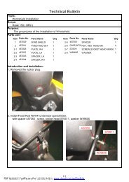
4-3-5 RESISTORDisassembly: Remove front windshield cover.Measure: A. Use megga meter‘s positive terminal to connect resistor wire.B. Connect the megga meter‘s negative terminal with frame ground andmeasure the resistance.Note: Resistor standard:20 W 5.9 Ohm: 5.0~7.0 Ohm.5W 5.0 Ohm: 4.0~6.0 Ohm.4-3-6 CDIUse megga meter to check the following items.A. Exciting Coil InspectionDisassembly: The exciting coil connector.Measure:A. Use megga meter‘s positive terminal to connect exciting coil’s black/red terminal.B. Connect the megga meter‘s negative terminalwith frame ground and measure the resistance.B. Pulse Coil InspectionDisassembly: The pulse coil connector.Measure:A. Use megga meter‘s positive terminal to connect pulse coil’s blue/yellow terminal.B. Connect the megga meter‘s negative terminal with body ground and measure theresistance.205PDF created with pdfFactory Pro trial version www.pdffactory.com
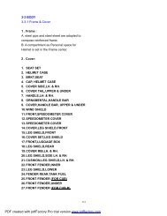
4-4 Removal and Installation of body4-4-1 Removal and Installation of Seatand CoverSeat:◎ Remove the nuts and pin.◎ Seat.◎ Remove 6 bolts on the helmet case.◎ Helmet case.Note:There is a coupler under the helmet case.And remove it.Additions of side cover:◎ Remove the handles.◎ Remove the bolts on the side cover.Leg shield:◎ Remove the bolts on the leg shield.(each side)◎ leg shield.Installation:Install in reverse order of removal procedures.206PDF created with pdfFactory Pro trial version www.pdffactory.com
Front fender:◎ Remove the bolts on the front fender.(each side)Mud guard:◎ Remove the bolts on the mud guard.(each side)125c.c.250c.c.Raer leg shield:◎ Remove the bolts on the rearleg shield.(each side)Installation:Install in reverse order of removal procedures.207PDF created with pdfFactory Pro trial version www.pdffactory.com
Fronnt leg shield cover:◎ Remove the nuts and screwon the fronnt leg shield cover.◎ Fronnt leg shield cover.Fronnt leg shield:◎ Remove the bolts on the fronnt leg shield.(each side)◎ Fronnt leg shield.Leg shield cover set:◎ Remove the bolts on the leg shield cover set.Installation:Install in reverse order of removal procedures.208PDF created with pdfFactory Pro trial version www.pdffactory.com
Wind shield:◎ Remove the bolts on the wind shield.(each side)◎ Wind shield.Front speedometer cover:◎ Remove the screws on theFront speedometer cover.(each side)Speedometer cover:◎ Remove the screws on thespeedometer cover.(each side)Installation:Install in reverse order of removal procedures.209PDF created with pdfFactory Pro trial version www.pdffactory.com
4-4-2 Removal and Inspection of Front Fork & Steering2CU8 & CUB11. FORK COMP, FRONT2. SHOCK ABSORBER ASSY3. SUSPENSION ARM, LH. &RH.4. FIXED PLATE, LH. & RH.43CU8-B & CUB-B11. FORK COMP, FRONT2. FORK COMP, FRONT LH. &RH.2211. H<strong>AND</strong>LE BAR ASSY2. GRIP3. CABLE4. CABLE, THRORRLE34210PDF created with pdfFactory Pro trial version www.pdffactory.com
CU8 & CUB:◎ Remove upper and lower boltson the shock absorber assy.◎ Shock absorber assy.◎ Remove the bolts on the suspension ram.◎ Suspension ram.CU8-B & CUB-B:◎ Remove the bolts on the fork comp.◎ Remove 4 nuts.◎ Fork comp, front LH. & RH.4-4-3 Removal and Assembly of Wheeland Shock absorberFront wheel:Watch: Please place main stand to park the motorcycleRemoval:for maintenance.◎ Remove 2 bolts on the caliper.◎ Caliper.◎ Remove bolt and collar.◎ Remvoe speed meter cable nut.Note: Do not apply brake when removing caliperfrom brake disk. Otherwise, the lining can contact.◎ Front wheel.Inspection: Check eccentricity and wear condition.Note: If eccentricity is higher than 0.2mm, pleasereplace with new one to ensure driving safety.◎ Speed meter gear assembly.*Inspection of Wheel Rim*Put wheel rim on rotation stand.Rotate the wheel slowly and usedial-gauge to measure eccentricityNote:(1) The transverse eccentricity should bewithin 3.0 mm. If the condition is poor,please replace with new one.(2) The lateral eccentricity should be within 3.0mm.If the condition is poor, please replace with new one.211PDF created with pdfFactory Pro trial version www.pdffactory.com
Rear wheel:Watch: Please place main stand to park the motorcycle for maintenance.Removal:◎ Remove 2 bolts on the caliper.◎ Caliper.◎ Remove the nut.◎ Rear wheel.Note:(1) Please use vacuum to clean wheel rim and lining.Try to reduce the contamination of asbestos fiber, whichmay affect the human breath system or lead to cancer.Speed meter cable(2) The transverse eccentricity should be within 3.0mm.If the condition is poor, please replace with new one.(3) The lateral eccentricity should be within 3.0 mm.If the condition is poor, please replace with new one.Installation:Install in reverse order of removal procedures.Shock absorber:Front:Watch: Please place main stand to park themotorcycle for maintenance.Removal:◎ Remove upper and lower attaching boltson front shock absorber.(each side 2 bolts)◎ Shock absorber.Inspection: Check if the shock absorber is worn,scratched, leaking, or bent. If its condition is poor,please replace with new one.Note: Torque of shock absorber upper and lowerattaching bolts: 200 ~ 300 kg-cm.Rear:◎ Remove 2 attaching bolts on air filter.◎ Air filter.◎ Remove upper and lower attaching boltson rear shock absorber.(each side 2 bolts)◎ Shock absorber.212PDF created with pdfFactory Pro trial version www.pdffactory.com
Inspection: Check if the shock absorber is worn,scratched, leaking, or bent. If its condition is poor,please replace with new one.Note: Torque of shock absorber upper and lowerattaching bolts: 200 ~ 300 kg-cmInstallation:Install in reverse order of removal procedures.213PDF created with pdfFactory Pro trial version www.pdffactory.com
4-5 Brake system:CU8 & CUB213451365241:MASTER CYLINDER2:HOSE ASSY3:CALIPER4:PAD ASSY5:DISC,BRAKE6:REAR FORK ASSY214PDF created with pdfFactory Pro trial version www.pdffactory.com
CU8-B & CUB-B213541365241:MASTER CYLINDER2:HOSE ASSY3:CALIPER4:PAD ASSY5:DISC,BRAKE6:REAR FORK ASSY215PDF created with pdfFactory Pro trial version www.pdffactory.com
A. Check of braking fluid levelInspection: The front brake fluid level should above “LOWER”.If it is below, refill the brake fluidand check leakage of the brake system.Adding of braking fluid:● Stand the scooter at its main rest on a leveled floor.● Turn open the fuel tank cap and add in designatedbraking fluid to the maximum.Warning: 1) Add in designated braking fluid, a different fluid would cause hazardouschemical reaction, leading to failure in braking.2) Keep water off the fluid cup or the boiling point would drop to produce airblock, leading to failure in braking.3) In case of spill of braking fluid to plastic parts, wipe it off with a rag foraestheticism.B. Checking and adjustment of freebraking gaps.Note: front brake free gap of 10 ~ 20 mmAdjustment of braking gap: ● Front windshield●Turn lose the securing nuts, tighten the screws.Remark : 1) Turn it clockwise to enlarge the gap.2) Turn it counterclockwise to reduce the gap.3) Keep the free gap at between 10 ~ 20 mm andtighten the nut.C. Inspection of the Return Spring of Brake Lining:a. Testing the free length of the spring with a vernier caliper.b. Check for any wear and crack on the spring.Free Length of the Return Spring of Brake Lining (mm)Standard 32.6-33.0 Limit Exchanged over 35.0D. Inspection of the Brake Cam:a. Check for any rust or unusual wear on the brake cam.216PDF created with pdfFactory Pro trial version www.pdffactory.com
. Make sure the brake cam runs smoothly.c. Make sure to apply sufficient grease to the brake cam and lining anchor-pin.E. Inspection of Front Brake:a. Check the gap between the ends of front brake lever.Gap of Front Brake Lever10 ~ 20 mmb. Add brake oil.c. Check the brake lining.F. Inspection of Rear Brake:a. Check the gap between the ends of rear brake lever.b. Move the adjusting nut of brake cable clockwise to proper gap.Gap of Rear Brake Lever10~20 mm217PDF created with pdfFactory Pro trial version www.pdffactory.com