500 - X5 (CF500-5A) - Technical Service Manual ... - Mojo Motorcycles
500 - X5 (CF500-5A) - Technical Service Manual ... - Mojo Motorcycles
500 - X5 (CF500-5A) - Technical Service Manual ... - Mojo Motorcycles
- No tags were found...

Create successful ePaper yourself
Turn your PDF publications into a flip-book with our unique Google optimized e-Paper software.
CF<strong>500</strong>-5 SERVICECF<strong>500</strong>-<strong>5A</strong> MANUALWWW.CFMOTO.COM
WWW.CFMOTO.COMAll rights reservedZhejiang CFMOTO Power Co., Ltd.April. 2009
CFMOTOMain Data TableItemParameterModelCF<strong>500</strong>-5/CF<strong>500</strong>-<strong>5A</strong>Length CF<strong>500</strong>-5: 2100mm CF<strong>500</strong>-<strong>5A</strong>: 2300mmWidth1180m mHeight1230mmWheel base CF<strong>500</strong>-5: 1290mm CF<strong>500</strong>-<strong>5A</strong>: 1490mmEngine typeCF188Displacement 493Cm 3Fuel typeUnleaded gasoline RQ-90or aboveDry weight CF<strong>500</strong>-5: 344 kg CF<strong>500</strong>-<strong>5A</strong>: 358 kgNumber of PassengersCF<strong>500</strong>-5:2 ( Include driver)Max. Load210 kg25×8-12 40JFront TireTire185/80-12 40JRear Tire25×10-12 47J270/60-12 47JMin. Ground ClearanceMin. Ground ClearanceTurning DiameterTurning DiameterStartingElectrical starting, <strong>Manual</strong> StartingEngine TypeSingle cylinder, 4-stroke, Liquid-cooled, 4valves, OHCCombustion Chamber Type Triang leValve Driving TypeSOHC /Chain DriveBore ×Stroke87.5mm×82.0mmEngine Compression Ratio 10.2:1Lubrication TypePressure & SplashOil Pump TypeRotorLubricant Filter TypeFull flow filter screenOil TypeSAE15W-40/SFCooling TypeClosed coolant circulationCoolant Type-35℃ anti-rust coolant1-4
1 Maintenance InformationFuelDeviceGearingSteeringDeviceBrake TypeItemP aram eterAir Filter typeSponge element filterTypeVacuum Diaphragm typeCarburetorMIKUNI BSR 36-89Diameter of mixing 36mmvalveClutch Wet, Auto-CentrifugalOperationModeAutom atic( CVT) +Parking & Gear ShiftingGears Shift Low Gear, High Gear & Reverse GearShiftMode/order<strong>Manual</strong> /L-H-N-R( CVT )Transmissio 2.88~ 0.70n RatioFinal Ratio 1.333( 24/18, Bevel Gear)SecondaryRatio1.952( 41/21)GearLow Gear : 2.25(36/16) ; High Gear :Ratio Gears1.350(27/20) ; Reverse Gear :1.471(25/17)TotalLow Gear5.857 ; High Gear : 3.514 ;Reverse Gear: 3.828Axle RatioFrontAxle33 / 9 = 3.667RearAxle33 / 9 = 3.667Engine Output M ode Front/Rear ShaftDirection of OutputRotationClockwise on forward shiftSteering Inner 31ºAngle Outer 31ºFrontHydraulic DiscRearHy draulic DiscBumperSuspensionDeviceFrame TypeSwing ArmWelded Steel Tube and Plate11-5
CFMOTOMaintenance Data TableLubrication SystemItem Standard <strong>Service</strong> LimitEngine Oil Volume whenCapacity replacingVolume whenreplacing filterRecommended Oil(See Original)1900mL2200mL·Specially for 4-stroke motorcycleSAE-15W-40Substitutes must be used in thefollowing range.API type: SE or SF gradeSAE type: Choose from the leftchart according to theenvironmental temperature--Oil Pump RotorGap betweenInner and OuterRotorsGap betweenOuter rotor andbodayOil pressure0.03~0.1mm0.03~0.1mm130-170KPa at 3000r / min0.15mm0.12mmFuel SystemItemStandardFuel Tank Capacity Full capacity 19LTypeMIKUNI BSR36-89Jet Number07G0Mixing Valve Diameter(mm) 36mmMain JetN102221-130#CarburetorMain air Jet MD13/24 -35#NeedleJ8-5E26Main Nozzle785-401011-P-0MIdle JetN224103-22.5#Idle Adjusting Screw604-16013-1AIdle Speed1300±100r / min1-6
1 Maintenance InformationCylinder + Piston + Piston Ring+ CrankshaftItemStandardOperationLimitCylinder Pressure1000kPaFit Clearance betweenPiston and Cylinder0.030-0.051 0.1587.460-87.480Piston Skirt dia.Testing the point away skirt end 87.38010mmInternal dia. of Cylinder 87.<strong>500</strong>-87.522Plainness of CylinderAdjoining Plant0.015 0.05Piston Ring Free GapTop Ring R 11.7 round 8.92 nd Ring R 12 round 9.5Piston Ring Closed GapTop Ring 0.15-0.30 0.602 nd Ring 0.15-0.30 0.60Piston Annular FitTop Ring 0.04-0.08 0.180Clearance 2 nd Ring 0.03-0.07 0.150Thickness Piston RingTop Ring 0.97-0.992 nd Ring 1.17-1.19Top Ring 1.03-1.05Piston Annular Width 2 nd Ring 1.22-1.24Oil Ring 2.51-2.53Internal dia. of Piston PinBore23.002-23.008 23.030Exterior dia. Piston Pin 22.995-23.000 22.980Rod Small End Inner dia. 23.006-23.014 23.040Rod Big End Gap 0.10-0.55 1.0Rod Big End Thickness 24.95-25.00Crankshaft Run-out 0.03 0.08(mm)Remark11-11
CFMOTOClutch + Transmission(mm)Item Standard Limit RemarkClutch Friction plate inner dia. 140.00-140.15 140.50Clutch Joint RotationClutch lock-up Rotation1800-2400r/min3300-3900r/minDrive Belt Width 35.2 33.5Driven Disc Spring Free Length 168 160Shifter and fit flute gap 0.10-0.40 0.50Left Shifter Sliding Thickness 5.8-5.9Right Shifter Sliding Thickness 5.8-5.9Plunging Flute Width 6.0-6.2Driven Output Gear Sliding Width 6.0-6.21-12
1 Maintenance InformationTightening TorqueItem Torque N·m(kgf·m) Item TorqueN·m(kgf·m)5mm Bolt, nut 5(0.5) 5mm Screw 4(0.4)6mm Bolt, nut 10(1.0) 6mm Screw 9(0.9)8mm Bolt, nut 22(2.2) 6mmSH Bolt with flange, 10(1.0)10mm Bolt, nut 34(3.5) 6mm Bolt with flange, nut 12(1.2)12mm Bolt, nut 54(5.5) 8mm Bolt with flange, nut 26(2.7)10mm Bolt with flange, nut 39(4.0)For others not listed in the chart, refer to the standard tightening torque.Notes: Apply some engine oil on the part of screw thread and adjoining surface.ItemThread Dia. Quantity Torque(mm)N·m(kgf·m)Remark1Upper Front Mounting Bolt, Engine M8×60 1 35~45Upper Rear Mounting Bolt, Engine M10×1.25×110 1 40~50Upper Rear Mounting Bracket Bolt,Engine M8×14 1 35~45Upper Front Mounting Bracket Bolt,Engine M8×14 1 35~45Low Mounting Bolt, Engine M12×1.25×140 2 50~60Bolt, Swing Arm M10×1.25×70 16 40~50Bolt, Rear Absorber M10×1.25×50 4 40~50Bolt, Front Absorber M10×1.25×50 4 40~50Bolt, Rear Wheel Shaft Holder M10×1.25×100 4 40~50Mounting Nut, Rim 901-07.00.02 M20 16 50~60Nut, Rim Shaft 901-07.00.03 M10 4 110~130Mounting Screw, Rear BrakeCaliper M6×25 2 18~22Bolt, Rear Brake Caliper M10×1.25×20 2 40~50Bolt, Front Brake Disc 901-08.00.03 M8× 8 25~30Bolt, Front Brake Caliper M8×14 4 35~45Locknut, Steering Stem M8×55 4 20~30Nut, Steering Stem M10×1.25 4 40~50Locknut, Steering Shaft M14×1.5 1 100~120Rear Mounting Bolt, Muffler M8×30 1 30~35Bolt, Exhaust Pipe M8×14 1 30~35Mounting Bolt, Exhaust Pipe M8×40 1 30~35Mounting Bolt, Rear Axle M10×1.25×110 2 40~50Mounting Bolt, Front Axle M10×1.25×90 1 40~50Mounting Bolt, Front Axle M10×1.25×25 2 40~50Back End Bolt, Rear Trans Shaft 901-30.00.01 6 40~50Front End Bolt, Rear Trans Shaft 901-29.00.01 4 35~45Bolt, Front Trans Shaft 901-29.00.01 8 35~45Thermo Switch CF250T-420<strong>500</strong> 1 9~12Mounting Bolt 1, Front Rack M8×14 2 35~45Mounting Bolt 2, Front Rack M6×12 2 25~30Mounting Bolt , Rear Rack M8×14 4 35~451-13
CFMOTOEngine Tightening Torque TableItem Q’ty Screw dia.(mm)Torque(N.m)RemarkSensor, Reverse Gear 1 M10×1.25 20Spark Plug 1 M12×1.25 18Water Temperature Sensor 1 Rc1/8 8 Apply screw thread sealantValve Clearance Adjusting Nut 4 M5 10Drive Disc Nut 1 M20×1.5 115Driven Disc Nut 1 M20×1.5 115Circle Nut, Driving Disc 1 M30×1 100Nut, Front Output Shaft 1 M14×1.5 97Nut, Drive Bevel Gear 1 M22×1 145Nut, Driven Bevel Gear 1 M16×1.5 150Fixing Nut, Clutch 1 M18×1.5 70 Left handedLimiting Nut, Driven Bevel Gear Shaft 1 M60 110 Apply screw thread sealantLimiting Nut, Front Output Shaft 1 M55 80Apply screw threadsealant, left handedBolt, Swing Arm Shaft 2 M14×1.25 28Drain Bolt 1 M12×1.5 30Mounting Bolt, Overriding Clutch 6 M8 26 Apply screw thread sealantMounting Bolt, Magneto Stator 3 M6 10 Apply screw thread sealantBolt, CVT Windshield 3 M6 10 Apply screw thread sealantLink Bolt, Oil Pipe 2 M14×1.5 18Mounting, Oil Pump 3 M6 10Mounting Bolt, Pressure Limiting Valve 2 M6 10Bolt, Drive Bevel Gear Cover 4 M8 32Bolt, Driven Bevel Gear Cover 4 M8 25Locating Bolt, Shift 1 M14×1.5 18Flange Bolt, Fan 1 M10×1.25 551-14
1 Maintenance InformationItem Quantity Diameter(mm)Torque(N.m)Remark1Bolt, Crankcase14 M6 103 M8 25Bolt, Driven Sector Gear 1 M6 12Mounting Bolt, Oil Filter 1 M20×1.5 63Oil Filter 1 3/4?( 16 /in 18~20Bolt, Starting Motor 2 M6 10Bolt, Cylinder Head 4 M10 38Bolt, Cylinder Head(2 sides) 2 M6 101 M8 25Upper and Lower Bolt, Cylinder 4 M6 10Bolt, Cylinder Head Cover 12 M6 10Bolt, Chain Tensioner 2 M6 10Nut, Chain Tensioner 1 M8 8Bolt, Radiator Fan 3 M6 10Thermostat Bolt 2 M6 10Bolt, Water Pump Cover 3 M6 6Mounting Bolt, Water Pump 2 M6 10Fixed Bolt, Timing Sprocket 2 M6 15 Apply screw thread sealantM5 4.5-6Bolt without remarksM6 8-12M8 18-251-15
CFMOTOEngine ToolsMeasuring ToolsNo Name Type Function Remark1 Vernier Calipers 0-150mm measure length and thickness2 Micrometers 0-25mmmeasure the outer diameters of swingarm, valve rod and camshaft3 Dial gauge 25-50mm Measure max. lift range of camshaft4 Dial gauge 75-100mm Measure piston skirt5 Inner dia. Gauge, Cylinder Measure inner dia. of cylinder head6 Inner dia. Gauge, 10-34mmInner dia. of swing arm, piston pin hole,and rod head hole7 Dial Test Indicator 1/100 Run-out8 Knife Straight Edge plainness9 Feeler Gauge Plainness, adjusting valve clearance10 Fuel Level Gauge Fuel level length of carburetor11 Plastic gauge Fit clearance12 pull tension gauge Spring bounce13 Tachometer Engine rotation rate14 Cylinder Pressure Meter pressure in cyclinder15 Oil Pressure Gage Oil pressure16 Barometer Opening pressure of radiator cover17 Ohmmeter Resistance and voltage18 Amperemeter Opening of currency / switch19 Thermometer Liquid temperature20 Timing Lights Test spark timing21 Torque Tester One Set Tightening torqueAuxiliary Measuring Instrument22 Alcohol Burner Warming up23 Magnet Stand Install dialgauge24 Slab Auxiliary measure supplementary25 V-Block Run-out supplementary26 Forcep Install valve clip27 Plier Disassemble and install circlip28 Joint Plier Disassemble and install flange29 Impact Driver Disassemble cross recessed bolt30 Slot Type Driver31 Cross Type Driver1-16
1 Maintenance InformationSpecial Purpose ToolsNo Name Type Function Remark11 Spark Plug Wrench 172MM-022400-922-004Disassemble/ install sparkplug2 CVT WrenchCF188-051000-922-001CF188-052000-922-001Disassemble/install CVTdrive/driven disc nut3 Oil Filter Wrench CF188-011300-922-001 Disassemble/ install oil filter4 Piston Pin Remover CF188-040004-922-002 Disassemble piston pin5Magneto statorRemoverCF188-031000-922-001Disassemble magnetostator6 Crankcase Dissociator Divide L/R crank case7 Crank Remover8 Crank ToolDisassemble crank shaftfrom left crankcaseInstall crank shaft on leftcrankcase9Valve SpringCompressorCF188-022006-922-001Disassemble/ install valvespring10 Valve Former CF188-022004-922-001 Grind valve11 Circle Nut Wrench CF188-052000-922-00312 Driven Disc Clamp CF188-052000-922-00413 Driven Disc Former CF188-052000-922-00214 Limiting nut Wrench CF188-062204-922-001Disassemble CVT drivendiscDisassemble CVT drivendiscDisassemble CVT drivendiscDisassemble driven bevelgear bearing limiting nut15 Bearing Tool One full set Install bearing and oil ring16 Bearing Remover One full set Disassemble bearing17 Oil Ring Remover Disassemble bearing18 Limiting Nut Wrench CF188-060008-922-001Disassemble front outputshaft bearing limiting nutDisassemble fan connector19 Fixing Wrench CF188-A-180003-922-003flange, adjust valveclearance1-17
CFMOTOLubricant goose, Sealing OilCoated Section Attention GreaseTurning BearingsThrottle Cable Connecting PortionThrottle Pedal Movable PartsBrake Pedal Movable PartsSwing Arm Movable PartsSteering Inner Circle SurfaceSeat Lock Movable PartsTransmission Movable PartsMulti-purposegreaseOperation Material and Installment Supplementary of EngineEngine operation materials include lubricant (oil), grease (lubricant grease) and coolant, installmentsupplementary includes plane sealant and screw thread sealant.Name Type Parts RemarkSpecially for 4-strokeRotating section and carriage in cylinder,lubricant/oilmotorcycleSAE-10W-40、20W-50Substitutes must be usedin the following range.Rotating section and carriage in crankcaseRotating section and carriage in cylinderheadcapacity2200m L(replace oil)2300 m L(replace oil filter)API type: SE or S G grade(Replacement see 1-3)See Lubrication Systems Diagram(5-14)2600 m L(engine overhaul)Lubricant withPiston pin, valve rod part, valve ring, cammolybdenumshaftGrease/lubricant# 3 MoS 2 l ithium basedOil seal lip, O ring and other latex sealing,greasegreasebearing with seals, and CVT bearing/housingCoolant-35℃ anti-frozen, anti-rust,high –boiled coolantCooling system, water sealsCapacity based on radiatorpipe systemPlane sealantCoupling surfaces of cases, cases andcylinder, cylinder head and cylinder headcoverScrewthreadSome screw threadsealant1-18
1 Maintenance InformationWirings, Pipes, Cable Routing11-19
CFMOTO1-20
1 Maintenance Information11-21
CFMOTO1-22
CFMOTOValve System + Cylinder Head(mm)Item Standard Operation LimitValve DiameterValve Clearance( Idle Speed)Fit Clearance between ValveGuide and Valve StemIntake 30.6Exhaust 27.0Intake 0.05-0.10Exhaust 0.17-0.22Intake 0.010-0.037Exhaust 0.030-0.057Internal dia. of Valve Guide Intake & Exhaust 5.000-5.012Exterior dia. of Valve StemIntake 4.975-4.990Exhaust 4.955-4.970Valve Stem Run-out Intake & Exhaust 0.05Length of Valve Stem End Intake & Exhaust 2.9-3.1 2.3Thickness of Valve Head Intake & Exhaust 0.5Valve Head Seal Run-out Intake & Exhaust 0.03Width of Valve Seats Seal Intake & Exhaust 0.9-1.1Length of Valve Spring Intake & Exhaust 40 38.8Valve Spring TensionIntake & ExhaustTension182-210N/Length31.5mmCam HeightFit Clearance betweenCamshaft Exterior dia. &Bore.Camshaft Exterior dia.Camshaft Bore Internal dia.Intake 33.430-33.490 33.130Exhaust 33.<strong>500</strong>-33.560 33.200φ22 0.032-0.066 0.150φ17.5 0.028-0.059 0.150φ22 21.959-21.980φ17.5 17.466-17.484φ22 22.012-22.025φ17.5 17.512-17.525Camshaft Run-out 0.10Rocker Arm Internal dia. Intake & Exhaust 12.000-12.018Rocker Arm Shaft Exterior dia. Intake & Exhaust 11.973-11.984Plainness of Cylinder HeadAdjoining PlantPlainness of Cylinder HeadCover Adjoining Plant0.03 0.050.03 0.051-10
CFMOTOEngine Tightening Torque TableItem Q’ty Screw dia.(mm)Torque(N.m)RemarkSensor, Reverse Gear 1 M10×1.25 20Spark Plug 1 M12×1.25 18Water Temperature Sensor 1 Rc1/8 8 Apply screw thread sealantValve Clearance Adjusting Nut 4 M5 10Drive Disc Nut 1 M20×1.5 115Driven Disc Nut 1 M20×1.5 115Circle Nut, Driving Disc 1 M30×1 100Nut, Front Output Shaft 1 M14×1.5 97Nut, Drive Bevel Gear 1 M22×1 145Nut, Driven Bevel Gear 1 M16×1.5 150Fixing Nut, Clutch 1 M18×1.5 70 Left handedLimiting Nut, Driven Bevel Gear Shaft 1 M60 110 Apply screw thread sealantLimiting Nut, Front Output Shaft 1 M55 80Apply screw threadsealant, left handedBolt, Swing Arm Shaft 2 M14×1.25 28Drain Bolt 1 M12×1.5 30Mounting Bolt, Overriding Clutch 6 M8 26 Apply screw thread sealantMounting Bolt, Magneto Stator 3 M6 10 Apply screw thread sealantBolt, CVT Windshield 3 M6 10 Apply screw thread sealantLink Bolt, Oil Pipe 2 M14×1.5 18Mounting, Oil Pump 3 M6 10Mounting Bolt, Pressure Limiting Valve 2 M6 10Bolt, Drive Bevel Gear Cover 4 M8 32Bolt, Driven Bevel Gear Cover 4 M8 25Locating Bolt, Shift 1 M14×1.5 18Flange Bolt, Fan 1 M10×1.25 551-14
Overhaul Info……………………………………2-1Troubleshooting……………………………………2-1Front Rack, Bolt Cap………………………………2-2Seat, Seat Support & Rear Rack……………………2-3Front Top cover, Dashboard Cover…………………2-4Side Support(LH&RH)……………………2-5Rear Top Cover……………………………………2-6Left Side Panel……………………………………2-7Right Side Panel……………………………………2-8Fuel Tank Top Cover, Front Fender…………………2-92 Vehicle Body and MufflerFootrest Board (LH, RH)…………………………2-10Rear Fender, Engine Skid Plate (Front, Center, Rear),Double Seat, Protection Plate……………………2-11Front Inner Fender (R&H), Front Protector (RH, LH)…2-13Rear Protector (RH,LH), Bumper, Bumper Protector…2-14Bumper Cap……………………………………2-15Front Vent Grille, Fuel Tank………………………2-16Bottom Plate, Fuel Tank…………………………2-17Muffler……………………………………………2-18Description of Visible Parts………………………2-192Overhaul InformationOperation CautionsWarningGasoline is highly flammable, therefore smoke and fire are strictly forbidden in the work place.Special attention should also be paid to sparks. Gasoline may also be explosive when it isvaporized, so operation should be done in a well-ventilated place.Remove and Install muffler after it is fully cold.•This chapter is on the disassembly and installation of rack, visible parts, exhaust pipe, mufflerand fuel tank.•Hoses, cables and wiring should be routed properly.•Replace the gasket with a new one after muffler is removed.•After muffler is installed, check if there is any exhaust leakage.Tightening torqueMuffler Rear Fixing Bolt: 35-45N.mMuffler Exhaust Pipe Bolt: 35-45N.mMuffler Body Fixing Bolt: 35-45N.mTroubleshooting•Loud exhaust noise• Broken muffler• Exhaust leakageInsufficient power• Distorted muffler• Exhaust leakage• Muffler clogged2-1
CFMOTOFront Rack, Bolt CapRemove:Upwardly remove Bolt cap hard; two assemblybolts of front rack shall be seen.Remove fixing Bolt 1(one for each on theleft and right)Romove fixing Bolt 2Remove front rackInstallation:Reverse the removal procedure for installationTightening Torque:Fixing Bolt 1, Bolt 2 35 N.m -45N.mFixing Bolt 3, Bolt 425 N.m -30N.m2-2
2 Vehicle Body and MufflerSeatRemove:Pull upward seat buckleLift and push seat backward2Installation:Press upward seat bucklePress seat forward and downNote:Shake seat left,right, front and back to make sure thatthe seat is firmly installed.Remove:-seat ( 2-3)—Bolt 1, bolt 2Remove seat supportRemove Bolt 3 for rear rack and rear fenderfrom rear fender bottomRemove Bolt 1Remove Rear RackInstallationReverse the removal procedure for installationTightening Torque:Bolt 1:35N.m-45N.mBolt 2:35N.m-45N.mBolt3:8N.m-12N.m2-3
CFMOTOFront Top CoverRemoveFront Rack(2-2)6 nuts,Front Top CoverAssembleReverse the removal process and direction.Dashboard CoverRemove--2 pieces Bolt 1--2 pieces bolt 2--Dashboard CoverInstallationReverse the removal process and direction.2-4
2 Vehicle Body and MufflerFront Side Support(Left)RemoveBolt 1Front Side SupportAssemble2Reverse the removal process and direction.Front Side Support(Right)Same as Left Side Support2-5
CFMOTORear Top CoverRemoveRear Rack(2-3)Seperate clasps of rear top cover from rearfender;Remove Rear Top CoverInstallationReverse the remove procedure anddirection for installation .Gear Shift Unit FenderRemove--Bolt 1--Bolt 1--Bolt 2Remove Gear Shift Unit FenderInstallationReverse the remove procedure anddirection for installation .2-6
2 Vehicle Body and MufflerLeft Side CoverRemove--Seat(2-3)--Left Side Cover fixing bolt--Left Side Cover2InstallationReverse the remove procedure anddirection for installation .Rear ProtectorRemove--Rear Rack(2-3)--Rear Top Cover(2-6)--Rear Link Plate(2-7)--Rear Left Side Support(2-8)--Rear Right Side Support(2-8)--Rear Turning Light Connector--Bolt 1,2,1--Rear ProtectorInstallationReverse the remove procedure and directionfor installation.Rear Link PlateRemove--Bolt 3Rear Link PlateInstallationReverse the remove procedure and directionfor installation.2-7
CFMOTORear Side PanelRemove--Seat(2-3)--Right Side Cover FixingBoltRemove connecting Bolt 1 between RightSide Panel and Front Fender at bottomof Front FenderRemove Right Side PanelInstallationReverse the remove procedure anddirection for installation .Rear Right Side SupportRemove--Bolt 2--Remove Rear Right Side SupportInstallationReverse the remove procedure for installationRemoval and Installation andRear Right Side Support issame with Left side.2-8
2 Vehicle Body and MufflerTop Cover, Fuel TankRemove--Seat(2-3)--Front Rack(2-2)--Front Top Cover(2-4)--Left Side Panel(2-7)--Right Side Panel(2-8)--Bolt 1, 22--Bolt 3, 4--Fuel Tank CapRemove Fuel Tank Top CoverInstallationReverse the remove procedure anddirection for installation .Front FenderRemove--Front Rack(2-2)--Front Top Cover(2-4)--Left, Right Side Panel(2-7)(2-8)--Fuel Tank Top Cover(2-8)--Left,Right Side Support(2-5)Loosen Cable Connector of Front FenderRemove Electronics Parts of Front FenderRemove 3 Front Fender bolts fixed in FrameRemove 4 bolts fixed with left and rightfootrestRemove Front FenderInstallationReverse the remove procedure for installation2-9
CFMOTOFootrest,Left SideRemoveLeft Side Panel(2-7)Remove three Bolt 1 and 3 nuts connectingwith Front FenderRemove three Bolt 2 and 3 nuts connectingwith Rear FenderRemove Bolt 1Remove Left FootrestInstallationReverse the remove procedure for Installation.Footrest,Right SideRemoval and Installation same with Left side.2-10
2 Vehicle Body and MufflerRear FenderRemove--Seat(2-3)--Rear Rack(2-3)--Rear Top Cover92-60--Left,Right Side Panel(2-7)(2-8)--Lef,RightSide Support(2-8)--Rear Protector(2-7)Remove Battery Bracket and Fixing Plate(8-4)Remove Battery(8-4)Remove Bolt 1Remove Nut 1Remove Electonic Parts from Rear FenderLoosen Cable Connector from Rear FenderUpwardingly Remove Rear FenderEngine Front,Middle and Rear SkidPlate; Protector Plate of Double2Seat2-11
CFMOTODisasemblyNOTE:Side skid Plate(Front,Middle, Rear)and Double Seat Protection are locatedat bottom of vehicle. The mainteanaceperson should work under bottom of vehicle whendisassemble the above parts.For safty , make sure the vehicle isfirmly parked.Engine Skid Plate(Front)Remove Bolt 1, 2, 3,and 4;Remove Engine Front Skid PlateInstallationReverse the remove procedure for InstallationEngine Skid Plate(Middle)Remove Bolt 5 and 6;Remove Middle Engine Skid Plate.InstallationReverse the remove procedure for InstallationDouble-Seat Protection PlateRemove Bolt 7 and 8;Remove Double-Seat Protection Plate.NOTE: No Protection Plate for single-seat .InstallationReverse the remove procedure for InstallationEngine Skid Plate(Rear)RemovalRemove Bolt 9 and 10;Remove Rear Engine Skid Plate.InstallationReverse the remove procedure for Installation2-12
2 Vehicle Body and MufflerRight Front Inner FenderRemovalRemove Bolt 1 ,and remove Right Front InnerFender2InstallationReverse the remove procedure for InstallationNOTE: Hook Water Pump with Clip of RightInner Side Fender during Installation.Left Front Inner FenderRemovalRemove Bolt 1 ,and remove Left Front InnerFenderInstallationReverse the remove procedure for InstallationFront Left ProtectorRemove--Bolt 1Pull backward and remove front FrontLeft ProtectorInstallationReverse the remove procedure for InstallationFront Right ProtectorRemoval and Installation same with Left Side.2-13
CFMOTOFront Left Inner FenderRemovalRemove Bolt 1 and 2;Remove Front Left Inner FenderInstallationReverse the remove procedure for InstallationFront Right Inner FenderRemoval and Installation same as Left Side.Bumper, Bumper ProtectorRemoveRemove two Bolts of Engine Front Skid Platefixing into the Bumper.Remove Bolt 1, 2, 3 and 4.Remove Bumer and Bumper ProtectorRemove Bolt 5 connecting Bumper and Rack.2-14
2 Vehicle Body and MufflerBumper ProtectorRemove--Loosen Front Turning Light Connector.--Remove Bumper and Bumper Protector.Remove tapping screw 1 from Bumper;Remove Bumper Protector.2InstallationReverse the remove procedure for InstallationBumper Protector CapRemovePull the two Caps from Bumper(There are only 2 caps in this vehicle)InstallationPress Caps into Bumper Pipe2-15
CFMOTOFront Vent GrillRemove--Loosen Connector of Front Head Light--Remove Front Fender(2-9)--Remove Bumper(2-14)--Remove Bolt 1, 2 and 3;--Remove Vent GrillNote: For removal of front vent grille only,Just remove 2 fixing boltsof bumper and 2 center fixing bolts,then pull bumper downInstallation:Reverse the removal procedure for installationWarning: Gasoline is highly flammable,therefore smoke and fire are strictly forbiddenin the work place.Special attention should also be paid tosparks.Gasoline may also be explosive when itis vaporized,so operation should be done in a wellventilatedplace.Remove Left and Right Side Panel(2-7)Remove Front Fender(2-9)Remove Fuel Tank Top Cover(2-9)Remove Bolt 4Loosen Fuel Sensor 3P Connector.2-16
2 Vehicle Body and Muffler2Remove Fuel Pipe 1 and CirclipRemove Fuel TankInstallation:Reverse the removal procedure for installationNote:Be careful not to damage main cable,pipes and hoses. Main cable, cables,pipes and hoses should be routed properlyaccording to the routing drawing.Take precaution against fuel leakagewhen removing fuel Fuel Hose IRemove:--Fuel tank (2-16)--Bolt 1--Bolt 2--Fuel tank top coverInstallation:Reverse the removal procedure forinstallation.Note:Be careful not to damage main cable,pipes and hoses. Main cable, cables,pipes should be routed properly accordingto the routing drawing2-17
CFMOTOMufflerCaution: Perform disassembly onlyafter the muffler is cooled down.Remove:--Seat (2-3)--Right side panel (2-8)--Nut1, Nut 2 for exhaust pipe elbowRemove BoltRemove Bolt 2, Bolt 3Remove mufflerInstallation:Reverse the removal procedure forinstallation.Note:Replace sealing gasket when installingthe muffler.2-18
2 Vehicle Body and MufflerVisible Parts22-19
Overhaul Info……………………… 3-1Maintenance Interval………………..3-2Inspection & Maintenance………… ………3-3Steering Stem, Brake System……………...3-6Wheels……………………………… ……….3-8Suspension System………………. ………3-10Gear Shifting, Fuel Device……………… ...3-11Check the throttle………………................3-123.Checks & AdjustmentCooling System..…………………………3-13Lighting System...………………………...3-16Valve Clearance…………………………..3-17Engine Idle Speed & Spark plug…………3-18Air Filter……………………………….3-19Fuel Hose, Carburetor&Drive Belt..3-20Inspection of Lubrication System…………3-22Inspection of Cylinder Pressure…………..3-24Inspection of Clutch Engagement andLock-up……………………………………..3-263Overhaul infoOperation CautionsNote- DO NOT keep the engine running for long time in a poorly ventilated or enclosed placebecause of the harmful components like CO, etc, in the exhaust gas.- The muffler and engine are still very hot when the engine is just stopped. Careless contactmay cause serious burn. Be sure to wear fatigue dress with long sleeves and gloves ifthe work has to be done after the engine is just stopped.- Gasoline is highly flammable, smoking is strictly forbidden in the work place. Keep alerton the electrical sparks. Besides, vaporized gasoline is highly explosive, so work should bedone in a well-ventilated place.- Be careful that your hands or clothes not get nipped by the turning or movable parts of thedriving system.NoteThe vehicle should be parked on hard and level ground.3-1
CFMOTOMaintenance IntervalThe table below lists the recommended intervals for all the required periodic maintenancework necessary to keep the engine at its best performance and economy. Maintenanceintervals are expressed in terms of kilometer, miles and hours, whichever occurs first.Note: Maintenance interval should be shortened on engines that are used in severe conditions.IntervalInitialKm250kmItem Hours InitialEvery<strong>500</strong> kmEveryEvery1000 kmEveryRemarkValve Clearanc e20 hours 50 hours 100 hoursI — IIN: 0.05~0.10EX:0.17~0.22Idle Speed I I — 1300±100r/MinSpark PlugI — IReplace every 6000KmAir Filter— I CFuel Hose, Carburetor— — IClutch — — INo carbon depositGap: 0.8~0.9mmReplace20000 KmeveryReplace every 4yearsDrive Belt— I —Engine Oil R — ROil Filter R — RCoolant Level I I —Water Hose & Pipes I — IReplace2000KmeveryCoolantReplace every 2 yearsI=Inpection and adjust, or replace if necessaryR=ReplaceC=Clean3-2
3.Checks & AdjustmentInspection & Maintenance○: IntervalItemIntervalsPartItemDaily 1/2YearAnnualHandlebar Operation agility ○SteeringDamage○System○BrakeSystemDrivingSystemBufferSystemSteeringsystemBrake leverConnectingrod, oil pipe& HoseInstallation condition of steering systemSway of ball stud○StandardFree play ○ ○ Front: lever end 0mmRear : lever end 0mmBrake○ ○EfficiencyLooseness,Slack and damageFront and rear brake fluid level ○ ○Hydraulicbrake andbrake disc Brake disc damage and wear ○ ○WheelSuspensionarmShockabsorberTire pressure ○ ○Chap and damage ○ ○Groove depth and abnormal wearLoosened wheel nut and axle ○ ○Sway of front wheel bearing ○ ○Sway of rear wheel bearing ○ ○Sway of Joint parts, rocker armdamageOil leakage and damage ○ ○Function○○○○○○○Brake fluid should beabove LOWER limitReplace when thethickness of front brakedisc is less than 2.5mm,rear brake less than6.5mm.Front tire: 35kPa(0.350kgf/cm 2 )Rear tire:30kP a(0.30kgf/cm 2 )No wear indication on thesurface of tire (theremained depth of grooveshould not be less than1.6mm)3DriveTrainFront axle Transmission, lubrication ○ ○Rear axle Transmission, lubrication ○ ○Gear box Transmission, lubrication ○ ○Remove filling bolt, add oiltill oil level reaches edgeof filling hole.Final shaft(Drive shaft)Looseness of joint partsSway of Spline3-3
CFMOTODrive trainPartFinalshaft(Driveshaft)ItemIntervalsDaily 1/2ItemYearLooseness of joint parts O OSway of SplineAnnualElectricalIgnitionDeviceSpark plugIgnition timingOOSystem Battery Terminal Joint OWiringLooseness and damage ofjointsOFuel leakageOFuel deviceThrottleOCooling system Coolant level O OCoolant leakageOOStandardSpark plug gap:0.8-0.9mmThrottleclearance:3~5mmgrip3-4
3.Checks & Adjustment3PartItemItemIntervalsDaily 1/2AnnualYearLighting device andturning indic torsFunction ○ ○Alarm and lock device Function ○Instruments Function ○Exhaust pipe andmufflerFrameOthersAbnormal parts whichcan be determinedwhen driv ingLooseness or damagecaused by improperinstallationFunction of mufflerLooseness and/ordamageLubric ation & grease offrame partsMake sure if there is anyabnormal with relativeparts.○○○○○Standard3-5
CFMOTOSteering StemPark the vehicle on level place, hold steering handlebar,and shake in the direction as illustrated on the rightand see if there is any sway.In case of any sway, check if it is the problem of thesteering stem or other parts and then do the maintenanceaccordingly.In case of sway of the steering stem, tighten the locknutor disassemble the steering stem for further check.Park the vehicle on level place, slowly turn the handlebarleft and right to see if it can turn freely.In case there is any hindrance, check if it is from themain cable assembly or other cables.If no, check the steering tie-rod end, and check if thesteering stem bearing is damaged.Note:Make sure the steering can be operated freely.An accident may occurif the handlebar is out of control.Brake systemFront brake lever free playOperate front brake lever and check brake efficiencyand brake lever function.Check free play of front lever end.Free play: 0mm3-6
3.Checks & AdjustmentMaster CylinderCheck the brake fluid levelWhen the brake fluid level is near to the lower limitline, check master cylinder, brake hoses and jointsfor leakage. Remove the two mounting screws on fluidreservoir cap.Remove the cap, add DOT3 or DOT4 brake liquid tillthe upper limit line.3-Do not mix with dust or water when adding brakefluid.-Use only the recommended of brake fluidto avoid chemical reaction.-Brake fluid may cause damages to the surface of theplastic and rubber parts.Keep the fluid away from these parts.-Slightly turn the handlebar left and right till the mastercylinder is in horizontal, then remove the fluid reservoircap.Brake Disc, Brake Pad< Wear of brake pad>Check the brake pad wears from the mark as indicated.Replace the brake pad if the wear has reached positionof wear limit trough.Note The brake pad must be replaced with a wholeset.Checking and replacing the brake discFront brake disc thickness: ¡Ü2.5 mm ¡úReplaceRear brake disc: ¡Ü6.5 mm ¡úReplaceMin. limited thickness of the front brake disc: 2.5mmMin. limited thickness of the rear brake disc: 6.5mmChange the Brake Fluid< Changing Brake Fluid>Change the brake fluid once every year.3-7
CFMOTOWheelsLift front wheel on level place, and make sure there isno loading on the wheels.Shake the front wheel left and right to check whetherthe joint of front wheel is tightened and check whetherit sways.Not tighten enough: ¡úTighten itSway: Replace the rocker armFront Toe-in sizePark the vehicle on level place, measure the front toeinToe-in: B-A=0-10mmToe-in out of the range: ¡ú Adjust the locknut of tie-rodNote:After the toe-in has been adjusted, slowly run the vehicleto check whether the direction of vehicle can becontrolled by handlebar.3-8
3.Checks & AdjustmentTire PressureCheck the pressure of the tireswith a pressure gauge.NoteCheck the tire pressure after tiresare cooled.Driving under improper tire pressurewill reduce the comfort of operationand riding, and may cause deflectedwear of the tires.3Specified pressure /tireFront wheel Rear wheelPressure 35kPa(.035kgf/cm2) 30kPa(0.30kgf/cm2)Tire Size AT25¡Á8-12 AT25¡Á10-12Tire TreadCheck the tire tread.Tread Height: < 3mm¡úReplace with new tiresNote:When the tread height is less than 3mm, the tire shouldbe replaced immediately.3-9
CFMOTOWheel Nut and Wheel AxleCheck front and rear wheel axle nuts for loosenessLoosened axle nuts: TightenTightening Torque:Front wheel axle nut:110-130N.m(11.2kgf.m-13.3kgf.m)Rear wheel axle nut:110-130N.m(11.2kgf.m-13.3kgf.m)Sway of Wheel BearingLift the front wheelMake sure there is no loading on the vehicleShake the wheel in axial direction for any swayIn case of any sway,disassemble the front wheel and check the bearingSuspension SystemPark the vehicle on lever place, press the vehicle Severaltimes up and down as illustrated on the right.In case of any rocking or abnormal noise, check whetherthere is any oil leakage from absorbers, or any damageor looseness of tightening parts.3-10
3.Checks & AdjustmentAdjusting the AbsorberUse special tools to adjust the length ofabsorber according to loading requirementTurn clockwise to adjust from high to low3Gear ShiftingShift the gear to check for flexibility andgear engagementAdjust the gearshift rod if necessaryRelease the locknut to adjust the length ofgearshift rodFuel DeviceStatus of the fuel systemRemove the seat (2-3)Check the fuel hose for any aging or damage.Aged or damaged fuel hose: ReplaceCheck if there is cracks or bending with thevacuum tube.Cracked or bended vacuum tube: Replace3-11
CFMOTOChecking the Throttle LeverCheck the free play of throttle leverFree play: 3-5mmOut of range: AdjustLoosen locknut of throttle cableturn the regulator and adjust free play of throttle leverAfter adjusting, tighten locknuts and install throttlecable sleeveReplace with a new throttle cable if the specified freeplay could not be acquired by adjusting the regulatoror if there is still stickiness with the throttle.Adjusting the Speed LimiterThe speed limiter is to limit the opening of throttleCheck the maximum length of limiter screw threadMaximum screw thread: a=12mmAdjust with a cross driver.Note:For beginners, the speed limit should be fullytightened.Drivers with certain skills may adjustthe throttle with speed limiterMaximum length of screw thread is 12mm.It is recommended to adjust the thread length to 3-5mm.3-12
3.Checks & AdjustmentCooling SystemNoteCheck coolant level from reservoir tank.Do not check from radiator.If the radiator cap is opened while the engine is hot(over 100¡æ), the pressure of the cooling system willdrop down and the coolant will get boiled rapidly.3DO NOT open the radiator cap until the coolant temperaturedrops down.-Coolant is poisonous, DO NOT drink or splash it toskin, eyes, and clothes.-In case the coolant gets to the skin and clothes,wash with soap immediately.-In case the coolant gets into eyes, rinse with plentyof water and go to consult the doctor-In case of swallowing the coolant, induce vomit andconsult the doctor.-Keep the coolant in a safe place and away from reachof children.Coolant levelCoolant might reduce due to natural evaporation.Check the coolant level regularly.Note-freeze. Ordinary water may cause engine rust orcracks in winter due to freezing.-Park the vehicle on level ground for checking of thecoolant.Inclined vehicle body will cause incorrect judging ofthe coolant level.-Check the coolant after the engine is warmed up.Start and warm up engine.Stop the engine.Remove left side panel (2-6)Check if the coolant level is between the upper andlower limit.3-13
CFMOTOWhen the coolant level is below the LOWER limit,remove reservoir tank cap and add coolant till upperlimit.(Add coolant or diluted original liquid).Recommended coolant: CFMOTO coolantStandard density: 50%( Freezing temperature of coolant varies according tothe different mixture ratio. Adjust the mixture ratioaccording to the lowest temperature in the place wherethe vehicle is used.)If the coolant reduces very fast, check if there is anyleakage.The cooling system may be mixed with air when thereis nocoolant in the reservoir tank and the air should bedischargedbefore adding coolant.Coolant LeakageCheck radiator hose, water pump, water pipes andjoints for leakage.In case of any leakage, disassemble and do furthercheck.(Refer to Chapter 4)Check the radiator hose for aging, damages or cracks.The rubber hose will naturally get aged after a periodof service time. The aged hose may get cracked whenthe cooling system is heated. Nip the hose with fingersand check if there are any tiny cracks.In case of any abnormal, replace with a new hose.Check the clamps of the coolant pipes and hose.Tighten properly in case of any looseness.Check radiator fins for mud and dust clog or damage.Correct the bent fins; clean the mud with water andcompressed air. When the damaged area of the radiatorfin is over 20%, replace with a new radiator.3-14
3.Checks & AdjustmentInspection of Cooling SystemCheck initially at 50 hours or <strong>500</strong>km, replace coolantevery 2 years.Check radiator, reservoir tank and water hoses.Leakage or Damage: ReplaceCheck coolant level by observing the upper and thelower limit on the reservoir tank.If the level is below lower limit, fill coolant until thelevel reaches the upper limit.Replacing Coolant-Remove radiator cap1 and reservoir tank cap2.-Place a pan below water pump, and drain coolant byremoving drain plug3 and water hose4.-Drain coolant from reservoir tank.3Warning !-Do not open radiator cap when engine is hot, youmay be injured by escaping hot liquid or vapor.-Engine coolant is harmful. If coolant splashes in youreyes or clothes, thoroughly wash it away with waterand consult a doctor. If coolant is swallowed, inducevomiting and get immediate medical attention.-Keep coolant away from reach of children-Clean radiator with fresh water, if necessary.-Connect water hose4 and tighten drain bolt3 securely.-Fill the specified coolant into the radiator.-Loosen bleed bolt5 on water pump, when coolant flowfrom bleed bolt, tighten the bolt. Install radiator cap1securely after filling coolant.-Start the engine and keep it running for severalminutes. After warm up and cooling down the engine,open radiator cap and check coolant. Fill the specifiedcoolant until the level is between the upper andlower lines on the reservoir tank.Caution:Repeat the above procedures several times and makesure the radiator is filled with coolant and air isdischarged.Inspection of Cooling System3-15
CFMOTOCheck Water Temperature GaugeWhen engine is not working, the water temperatureshould be in the “0” position. Start the engine tocheck if the indicator works. If the indicator is notworking, do the maintenance in time.Lighting SystemAdjusting headlight light beamTurn the headlight beam adjusting screw with a crossscrewdriver and adjust the high/low beam to meet therequirement.3-16
3.Checks & AdjustmentVALVE CLEARANCEInspect initially at 20-hour break-in and every 100 hoursor every 1000km thereafter. Inspect the clearance afterremoving cylinder head.3Excessive valve clearance results in valve noise andinsufficient valve clearance results in valve damage andreduced power.Check the valve clearance at the period indicated aboveand adjust the valve clearance to specification, ifnecessary.-Remove cover plate1, recoil starter2-Remove inspection cap 3on left crankcase.-Remove 2 valve adjusting cover 4-Turn the crankshaft until the line5 of T.D.C. on rotoris aligned with mark6of inspection hole on leftcrankcase.-Insert feeler gauge to check the clearance betweenthe valve stem end and the adjust bolt on the rockerarm.Valve Clearance (When cold)IN: 0.05-0.10mm EX: 0.17-0.22mmNote:-The valve clearance must be adjusted when the engineis cold.-Adjust the valve clearance when the piston is at theTop Dead Center (T.D.C.) on the compression stroke.If the clearance is incorrect, bring it into the specifiedrange using the special tool.Loosen valve adjust bolt and nut, insert a feeler gauge(IN: 0.1mm, EX:0.2mm)between the valve stem endand valve adjusting bolt, tighten valve adjust bolt, makesure it slightly contacts the feeler gauge, tighten boltand nut.3-17
CFMOTOTake out the feeler gauge, measure the clearance.If the clearance is incorrect, repeat the above stepsuntil the proper clearance is obtained.Locknut: 10 N.mCaution:Securely tighten the locknut after completing adjustmentInstall:2 valve adjusting cover;Inspection cap;Recoil starter;Cover plate;Apply a small quantity of THREAD LOCKER to recoilstarter fixing bolts.Tools:Valve adjusterFeeler gaugeMaterial:Thread LockerENGINE IDLE SPEEDInspect initially at 20 hours run-in and every 50 hoursor <strong>500</strong>km thereafter.Start the engine and warm it up for several minutes,measure engine speed with a tachometer. Set theengine idle speed between 1200~1400 r/min by turningthe throttle stop screw of carburetor.Engine idle speed: 1300r/min¡À100r/minNote:Make this adjustment when the engine is hotTool: TachometerSPARK PLUGInspect initially at 20 hours run-in and every 100 hoursor 1000km thereafter. Replace every 6000km.Remove the spark plug with a special toolSpecification: DER7EA-9(NGK)If the electrode is extremely worn or burnt, or sparkplug has a broken insulator, damaged thread, etc, replacethe spark plug with a new one.3-18
3.Checks & AdjustmentIn case of carbon deposit, clean with a proper tool.SPARK PLUG GAPMeasure the spark plug gap with a feeler gauge.Out of specification: ¡ú AdjustSpark plug gap: 0.8-0.9mmCaution:Check the thread size and reach when replacing thespark plug. If the reach is too short, carbon will bedeposited on the screw portion of the spark plug holeand engine damage may result.Installation:Caution:To avoid damaging the cylinder head threads; first,tighten the spark plug with fingers, and then tighten itto the specified torque using the spark plug wrench.3Tightening Torque: 18 N.mTool: Spark Plug Wrench, Feeler GaugeAir FilterInspect every 50 hours or <strong>500</strong> km, clean it every1000km if necessary.If the air cleaner is clogged with dust, intake resistancewill be increased, with a resultant decrease inpower output and an increase in fuel consumption.Check and clean the air filter as following:Remove fixing clamp1 and top cover2Note:Be careful not to drop the o-ring into the air filter boxthat is attached to the air filter top cover.Loosen screw3, remove filter element4, separatesupport5, filter element6 and filter element seat7.-Fill a wash pan of a proper size with a non-flammablecleaning solvent A. Immerse the filter elementin cleaning solvent and wash it.-Press the filter element between the palms of bothhands to remove the excess solvent. Do not twist orwring the element or it will tear.-Immerse the element in engine oil B, and thensqueeze out the excess oil leaving the element slightlywet.3-19
CFMOTOA-Non-flammable cleaning solventB-Engine oil SAE#30 or SAE15W/40.Never use with gasoline or low flash pointsolvents to clean the filter elementInspect the filter element for tears.torn element must be replaced.Note:The surest way to accelerate engine wear is tooperate the engine without the element or withtorn element. Make sure that the air filterelement is in good condition at all times.If driving under dusty conditions, clean theair filter element more frequently.Remove the drain plug8 of air box to drain out any water.Fuel HoseInspect every 100 hours or 1000 km,replace every 4 years.Inspect the fuel hose for damage and fuelleakage.If any damages are found, replace the fuel hosewith a new one.Drive BeltRemoval:Remove CVT coverHold the primary sheave with special tool andloosen primary sheave nut.Special Tool: Rotor HolderRemove primary sliding sheave 1;Hold the secondary sheave with special tooland loosen secondary sheave nut.Remove secondary sheave together with drive belt.Special Tool: Rotor Holder3-20
3.Checks & AdjustmentInspection:Inspect drive belt for wear and damage.If any cracks or damages are found,replace drive belt with a new one.Inspect drive belt for width, if width isout of service limit, replace drive belt with a new one.<strong>Service</strong> Limit: 33.5mmTool: Vernier Caliper3InstallationReverse the removal procedure for installation.Pay attention to the following:Insert drive belt, as low as possible,between secondary sliding sheave and primaryfixed sheave.Hold secondary sheave with a special tool andtighten the nut to the specified torque.Nut, Secondary Sheave: 115 N.mInstall primary sheave and nut. Hold the primarysheave with a special tool and tighten the nutto the specified torque.Nut, Primary Sheave:115N.mTurn primary sheave, until the drive belt isproperly seated and both the primary andsecondary sheaves rotate together smoothlyand without slipping.Caution:-Fit the drive belt with the arrow on the drivebelt points toward normal turning direction.-The drive belt contact surface of the drivenface should be thoroughly cleaned.Install CVT cover3-21
CFMOTOInspection of Lubrication SystemReplace engine oil and oil filter initially at 20 hours or250km and every 100 hours or 1000km thereafter.Inspect the engine oil at every 10 hours.Check Engine Oil Level-Keep the engine in a plan position.-Remove the fixture A, fixture B, then remove the leftside cover 1.-Remove oil dip rod 2-Clean oil dip rod, insert oil dip rod but do not tightenit.-Take out oil dip rod and check if oil is between upperand lower limit.-If the engine oil is insufficient, fill more oil until thesufficient oil is obtained.Engine Oil: SAE15W/40 classification SF or SGNote:-Keep the engine in a plan position-Do not tighten oil dip rod when measuring oil levelReplacing Engine Oil-Remove left side cover 1, oil dip rod 2, drain bolt 3and washer 4.-Drain out the engine oil while the engine is still warm.-Clean oil dip rod, drain bolt and washer with solvent.-Install washer and drain bolt.Drain Bolt: 30 N.m-Fill engine oil. ( about 1900ml)3-22
3.Checks & Adjustment-Install oil dip rod, start the engine and allow it to runfor several minutes at idling speed.-Turn off the engine and wait for about 3 minutes, andthen check the oil level on the dipstick.Caution:The engine oil should be changed when the engine iswarm. If the oil filter should be replaced, replace engineoil at the same time.3Replacing Oil Filter-Remove relative parts ( see Replacing Engine Oil)-Remove oil filter1 with the special tool-Install washer and drain bolt-Install new oil filter with the special tool-Fill engine oil (about 2000ml) and check (see ReplacingEngine Oil)Tool: Oil Filter WrenchEngine Oil CapacityWhen replacing oil: 1.9LWhen replacing oil filer: 2.0 LEngine overhaul:2.2 LInspection of External Oil PipeCheck external oil pipe for leakage or damage.Leakage or Damage: Replace3-23
CFMOTOInspection of cylinder pressureCheck cylinder pressure is necessary.Cylinder Pressure: 1000kpaA lower cylinder pressure may be caused by:-Excessive wear of cylinder;-Wear of piston or piston ring;-Piston ring jam in groove;-Poor closure of valve seat;-Damaged cylinder gasket or other defectsNote: When cylinder pressure too low, check theabove items.Testing Cylinder PressureNote: Before testing of cylinder pressure, make surethat cylinder head bolts are tightened to the specifiedtorque and valve clearance has been properly adjusted.-Warm up the engine before testing;-Make sure battery is fully charged;-Remove spark plug 1;-Install cylinder pressure gauge 2 in spark plug holeand tighten nut;-Keep throttle full open;-Press start button crank the engine a few seconds.Record the maximum reading of cylinder pressure.Tools: Cylinder Pressure GaugeAdaptor3-24
3.Checks & AdjustmentInspection of Oil PressureOil Pressure: 130~170kpa at 3000r/minLower or higher oil pressure may be caused by:I Oil pressure is too low-Clogged oil filter;-Leakage from oil passage;-Damaged O-ring;-Oil pump failure;-Combination of above items;3II Oil pressure is too high-Oil viscosity is too high;-Clogged oil passage;-Combination of above items;Testing Oil Pressure-Remove bolt1;-Connect tachometer2with ignition coil-Install oil pressure gauge3 and joint seat to main oilgallery.-Warm up engine as per following:Summer: 10 minutes at 2000r/minWinter: 20 minutes at 2000r/minAfter warming up, increase engine speed to 3000r/min, and record readings of oil pressure gauge.-After testing, apply thread locker to the thread in thehole of main oil channel. Install bolt and tighten to thespecified torque.Tighten torque:23N.mTools:Oil pressure gaugeTachometer3-25
CFMOTOInspection of Clutch Engagement andLock-upCF188 engine is equipped with a centrifugal type automaticclutch.Before checking the initial engagement and clutchlock-up two inspection checks must be performed tothoroughly check the operation of the drive train.I Initial Engagement Inspection-Connect tachometer to ignition coil-Start engine-Shift gear lever to ¡°High¡± position-Slowly increase throttle and note down the enginespeed (r/min) when the vehicle starts to move forward.Engagement speed:1800r/min¡«2400r/minIf the engagement speed is out of the above range,check the following:-Clutch shoes-Clutch shoe wheel-Primary and secondary sheaveRefer to Chapter 12 for inspection of clutchII Clutch Lock-up Inspection-Connect the tachometer to ignition coil;-Start the engine;-Shift gear lever to “Hi”position;-Apply front and rear brakes as firmly as possible;-Fully open the throttle for a brief period and note themaximum engine speed obtained during the test cycle.Lock-up Speed: 3300r/min¡«3900r/minWarning:Do not apply full power for more than 5 seconds ordamage to clutch or engine may occur.If the lock-up speed is out of the above range, checkthe following:-Clutch shoes-Clutch wheel-Primary and secondary sheaveRefer to Chapter 12 for inspection of clutchTool: Tachometer3-26
Overhaul Info...................4-1Trouble Shooting................4-2Performance Overhaul............4-3Reservoir Tank..................4-<strong>5A</strong>dding Coolant..................4-6Cooling system chart............4-7Engine Coolant..................4-84 Cooling and Lubrication systemRadiator and water hose check and clean...4-9Cooling fan check.........................4-10Water temperature transducer check........4-11Water pump .............................. 4-12Water pump check .........................4-14Water pump assembly and installation.......4-15Lubrication system chart .................4-19Overhaul InfoCaution:.If the radiator cap is opened when the coolant temperature is above 100degrees(C),the pressure of coolanttemperature will go down and get boiled rapidly. The steam jet may cause danger and injury. Cover the capwith a piece of cloth after the coolant temperature goes down and open the cap..Inspection of coolant should be done after the coolant is fully cooled..Coolant is poisonous. Do not drink or splash it to skin,eye or cloth.-If coolant splashes in eyes, throughly wash your eyes with water and consult a docter.-If coolant splashes on your clothes, quickly wash it away with water and then with soap and water.-If coolant is swallowed, voimt immediately and see a physician.-Store the coolant properly and keep it away from reach of the children..Check radiator fins for mud block and/or damage. Correct the bent fins. Clean off the mud with water andcompressed air. Replace with a new one, if the damaged fin area reached 20%.The overhauling of the water pump can done without removing the engine..Coolant filling is carried through reservoir tank. Do not open the radiator cap except when disassembling thecooling system for filling or drainage of coolant..Don’t stain the painting parts with coolant. In case of any coolant stains, flush with water immediately..After disassembly of the cooling system, check the joints for leakage with a radiator cap tester(available in themarket)..Refer to Chapter 10 for overhauling of temperature transducer¡£Inspection standard4ItemStandardFull capacity1140mlCoolant capacityReservoir tank300mlStandard density 50%Opening pressure of radiator cap 108kpa(1.1kgf/cm 2 )Valve open temperature71±3degrees(c)ThermostatFull open liftunder 95 degrees(c),3.5-4.5mmTightening torque:Drainage bolt,water pump: 8N.m(0.8kgf.m)Water pump impeller: 10N.m(1.0kgf.m)4-1
Trouble shootingWater temperature rises too fast•Improper radiator cap•Air in the cooling system pipe•Malfunction of water pump•Malfunction of thermostat£¨thermostat is not open£©•Clogged of radiator pipe of cooling pipe•Damaged or clogged radiator fins•Coolant is not enough•Faulty or malfunction of fan motorNo rise or slow rise of water temperature•Malfunction of thermostat(thermostat isn’t closed)•Faulty circuit of water temperature displayWater leakage•Poor water seal•O-rings are aged, damaged or improperly sealed•Washers are aged, damaged or improperly sealed•Improper installation of pipes•Pipes are aged, damaged or improperly sealed.4-2
4 Cooling and Lubrication systemPerformance OverhaulInspection of coolant densityCaution:Be sure to open the radiator cap after coolant is cooled.Remove:Front top cover(2-4)Radiator cap(counter clockwise)Check with a densimeter if the density of coolant fitsthe temperature of using place;Check coolant for stains4Inspection of the radiator capCautionBe sure to open the radiator cap after coolant is cooledRemove:-Front top cover(2-4)-Radiator cap(4-3)CautionApply water on the sealing surface of radiator cap,when attaching the tester to the radiator capApply the specified pressure(radiator cap openingpressure) for 6 seconds and make sure there is nopressure drop.Opening pressure of radiator cap:108kPa(1.1 kgf/cm 2 )4-3
Pressure testing of cooling systemApply the specified pressure(radiator cap openingpressure) for 6 seconds and make sure that there isdrop in pressureCautionDo not apply pressure over the specified pressure[108kPa(1.1 kgf/cm 2 )],or the cooling system may bedamaged.In case there is any pressure leakage,check the pipe,joint parts,joints of water pump and drainage(4-5)Replacing Coolant,Air DischargePreparation of coolantCaution:Coolant is poisonous,DO NOT drink ot splash it toskin,eyes and clothes-If coolant splashed in your eyes,throughly wash youreyes with water and consult a doctor-If coolant splashed on your clothes,quickly wash itaway with water then with soap and water-If coolant is swallowed,induce vomit immediately andsee a physician-Store the coolant properly and keep it away from reachof childrenCaution:Mix the coolant(undiluted) with softwater according to the temperature 5¡ælower than the actual lowest temperature in the operationarea.Coolant should be made from undiluted coolant withsoft water.Standard density of coolant: 50%Recommended coolant: CFMOTO coolant(Direct application without having to bediluted)Drainage of coolantRemove the radiator capCautionOpen the radiator cap after the coolantis cooled down.Remove:-Front top cover(2-8)-Radiator Cap(4-3)4-4
4 Cooling and Lubrication systemRemove drain boltRemove drain bolt, seal gasket from waterpump, drain coolant.After drainage, assemble new seal gasketand drain bolt and tighten.4Reservoir TankRemove:-Seat(2-3)-Left Side Cover(2-6)-Two bolts of reservoir tank-Water hoses of reservoir tankRemove reservoir tankDrain collant of reservoir tankWash clean the reservoir tankInstall:-reservoir tank-water hoses of reservoir tank4-5
Adding CoolantAdd coolant through filling portStart the engine and discharge air from cooling system.Check from filling port that air is fully discharge fromcooling system and install the radiator capRemove reservoir tanl cap and add doolant till the upperlimitCaution:Chen coolant level when the vehicle is on an evengroundDischargeDischarge the air from cooling system according tothe following steps:1.Remove drain bolt(4-5),discharge air and install it2.Start the engine and run it several minutes at idlespeed3.Quickly increase throttle 3~4 times to discharge airfrom cooling system4.Add coolant till filling port5.Repeat step 2&3 till no more coolant can be refilled6.Check coolant level in reservoir tank and refill tillupper limit,install reservoir tank cap4-6
Cooling System Chart4 Cooling and Lubrication system44-7
Engine CoolantThe cooling used in cooling system is mixture of 50%distilled water and 50% ethylene glycol antifreeze. This50:50 mixture provides the optimized corrosionresistaance and fine heat protection.The coolant willprotect the cooling system from freezing at temperatureabove -30degrees(C),the mixing ratio of coolantshould be increased to 55% or 60% according to thefigure on the right.Note:•Use high quality ethylene glycol base antifreeze andmixed with distilled water.Never mix alcohol base antifreezeand different brands of antifreeze•lTheratio of antifreeze should not be more than 60%or less than 50%•lDo not use anti-leak additiveWarning!•DO NOT open radiator cap when the engine is stillhot.Or you may be injured by scalding fluid or steam;•Coolant is harmful.DO NOT swallow or stain yourskin or eyes with coolant.In case of accidental swallowor stain,flush with plenty of water and consult thedoctor immediately;•Keep coolant away from reach of childrenInspection of Cooling Circuit•Remove radiator cap1and connect tester2 fillerWarning!DOT NOT open the radiator when the engine is stillhot•Give a pressure of 105kPa and check if the coolingsystem can hold this pressure for 10 seconds.•If the pressure drops during 10 seconds,it indicatesthat there is leaakage with the cooling system.In thiscase,check the complete system and replace the leakingparts or components.Warning!•When removing the radiator cap tester,put a rag onthe filler to prevent splash of coolant•DO NOT allow a pressure to exceed the radiatorcap release pressure4-8
Inspection and Cleaning of Radiator and WaterHoses4 Cooling and Lubrication systemRadiator Cap•Remove radiator cap1•Install radiator cap to cap tester2•Slowly increase pressure to 108kPa and check ifthe cap hold the pressure for at least 10 seconds•If the cap can not meet the pressure requirement,repalce it4Radiator Cap Valve Opening Pressure:Standard:108kPaTool:Radiator Cap TesterRadiator Inspection and Cleaning•Remove dirt or trash from radiator with compressedair•Correct the radiator fins with a small screwdriverRadiator Hose Inspection•Check radiator hoses leakage or damage.If the hosesare leakaged and damaged,replace them•Check tightening of clamps.Replace the clamps ifnecessary•After inspection and cleaning of radiator and hoses,check coolant level.Fill coolant if necessary4-9
Inspection of Fan Motor•Remove fan motor from radiator•Turn the vanes and check if they can turn smoothly•Check fan motor.Make sure that the battery applies12 volts to the motor and the motor will run at fullspeed while the ammeter will indicate the ampere notmore than <strong>5A</strong>.If the motor does not work or the ampere exceeds thelimit,replace the motor•Installation:Apply a little thread locker to the boltsand tighten to the specified torque.Fan Motor Bolt Tightening Torque:10N.mInspection of Thermoswitch•Remove thermoswitch•Check the thermoswitch for closing or opening bytesting it at the bench as illustrated. Connect thethermoswitch1to the circuit tester,place it in a vesselwith engine oil. Place the vessel above a stove.•Heat the oil to raise the temperature slowly and takethe reading from thermostat 2 when the thermoswitchcloses and opens.Tool:ammeterThermoswitch Operating Temperature:Standard:(OFF-ON):Approx.88 degrees(C)(ON-OFF):Approx.82degrees(C)Note:•Avoid sharp impact on thermoswitch•Avoid contact of thermoswitch with thermometer orvessel•Installation:Use a new O-ring3 and tighten thethermoswitch to the specified torque:Thermoswitch Tightening Tirque:17N.m•Check coolant level after installation of thermoswitch.Fill coolant if necessary.4-10
4 Cooling and Lubrication systemInspection of Water Temperature Sensor•Plcae a rag under water temperature sensor1 andremove it from cyclinder head•Check the resistance of water temperature sensoras illustrated on theright. Connect the temperaturesensor2 to the circuit tester,place it in a vessel withengine oil.Place the vessel above a stove.Tool: ohmmeter, thermometer•Heat the oil to raise the temperature slowly and take4the reading from ohmmeter4 and thermometer3.Water Temperature andResistanceTemperature(℃)Resistance(Ω)50 80 100 120154±16 52±4 27±3 16± 2•Installation:Apply a little thread locker and install itto the cylinder head by tightening to the specifiedtorque.Water Temperature Sensor Tightening Torque:10N.mNote:•Avoid sharp impact on terperature sensor•Avoid contact of temperature sensor with thermometeror vessel•After installation,check the coolant level.Fill coolantif necessary.Inspection of Thermostat•Remove thermostat case•Remove thermostat4-11
•Check thermostat pellet for cracks•Test the thermostat according to the following steps:Pass a string between thermostat flange as illustratedon the rightImmerse the thermostat in a beaker with water.Makesure that the thermostat is in the suspended positionwithout contact to the vessel.Heat the water by placingthe beaker above a stove and observe the temperaturerise on a thermometerTake the temperature reading from thermometer whenthe thermostat valve opensThermostat Valve Opening Temperature:68-74degrees,CTool:ThermometerKeep heating the water to raise the watertemperature.When the water temperature reaches thespecified valve, the thermostat valve should have beenlifted by 3.5-4.5mmLift standard of thermostat valve:water temperature 95degrees(C),lift standard is3.5-4.5mmIf thermotat valve opening temperature or thermostatvelve lift does not reach the standards,replace it.•Inatall thermostat:Reverse the removal procedure forinstallationApply coolant to the rubber seal of thermostatInstall thermostat case.Tighten to the specified torque:Tightening Torques:10N.mWater PumpRemoval and Disassembly•Remove engine left side cover•Drain coolantNote:Before draining coolant, check water pump foroil or coolant leakage. In case of oil leakage, checkthe water pump oil seal, O-ring. In case of coolantleakage, check the water seal4-12
4 Cooling and Lubrication systemlRemove clamps and water hoseslRelease bolts and remove water pumplRemove O-ringNote:Do not reuse the O-ring4•Remove the overflow tube•Release water pump cover screws,water pump coverand gasket•Remove ring and impeller•Remove seal ring1 and rubber seal24-13
•Remove mechanical seal with special toolNote:The mechanical seal does not need to be moved,if there is no abnormal condition.Note:Do not reuse a removed mechanicalseal•Put a rag on the water pump body•Reomve oil sealNote:The oil seal does not need to be removed,if thereis no abnormal conditionNote:Do not reuse a removed oil seal•Remove bearing with special toolNote:The bearing does not need to be removed,if thereis no abnormal noiseNote:Do not reuse a removed bearingInspection of Water PumpBearing•Check the bearing clearance by hand,while it is stillin the water pump body•Turn inner race of bearing to check for abnormalnoise and smooth rotation•Replace the bearing,if there is abnormal conditionMechanical Seal•Check mechanical seal for damage,pay attentionto the seal face•In case of leakage or damage,replace the mechanicalseal. If nesessary,also replace the seal ring.4-14
4 Cooling and Lubrication systemOil Seal•Check oil seal for damaged. Pay attention to the oilseal lip.•In case of damage or leakage, replace the oil sealWater Pump Body4•Checl the mating mace of water pump body withbearing and mechanical seal.If damage,replace itWater Pump Impeller•Check the impeller and shaft for damage.•If the impeller or shaft are damaged,replace a newpartAssembly and Installation of Water Pump•Install oil seal with special tool;Tool:Oil Seal InstallerNote:The stamped mark on the oil seal faces outside.•Apply a little grease to the oil seal lip4-15
•Install mechanical seal with a suitable socket wrench.Note:Apply sealant to side”A”± of mechanical seal•Install bearing with special toolTool:Bearing InstallerNote:The stamped mark on the bearing faces outside.•Install seal ring to impeller•Clean off the oil and grease from mechanical sealand install into the impellerNote:”A”side of mechanical seal faces impeller•Apply grease to impeller shaft•Install impeller shaft to water pump body4-16
4 Cooling and Lubrication system•Install ring to water pump shaft•Install new gasket to water pump body4•Install water pump cover and tighten the bolts andbleed boltWater Pump Cover Bolts Tightening Torque:6N.m•Check impeller for smooth turning•Install the new O-ringNote:•Use the new O-ring to preventleakage•Apply grease to O-ring•Install the overflow tubes4-17
•Install water pump and tighten the bolts to the specifiedtorqueWater pump bolts tightening torque:10N.mNote:Set the water pump shaft slot end ¡°B¡± to oilpump shaft flat side”A”•Connect water hoses•Add coolant•Install left side cover4-18
4 Cooling and Lubrication system44-19
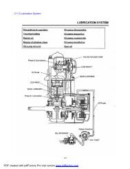
Add grease to the engine parts(piston,cylinder body,camshaft and so on) which run at high speedEngine lubrication should be special oil. Engine oil isnot only used as lubrication, but also used to wash,rustproof,seal and cool.4-20
5 Removal and Installation of Engine,Drive Traina and Gearshift UnitOverhaul Info...................................5-1Engine Removal and Installation........5-2Removal and Installation of Front and Rear Alex.....................................5-5Removal and Installation of Gearshift Unit............5-7Overhaul InfoOperation Cautions•Securely support the ATV with bracket when removing or installing engine.Take care not to damageframe,engine body,bolts and cables¡£•Warp the frame to avoid anyy possible damage when removing or installing the engine¡£•Following operation doesn’t require removal of engine from the vehicle:Oil pumpCarburetor, air filterCylinder head cover, cylinder head, cylinder body, camshaftCVT system, CVT coverGearboxRight side cover, AC magneto, water pumpPiston, piston ring, piston pinFollowing operation require removal of engine from vehicle:Crankshaft5Tightening torque:Engine front upper mounting bolt: 35N~45N.mEngine front rear mounting bolt: 40~50N.mBolt, engine front rear mounting bracket 35~45N.mBolt, engine front upper mounting bracket 35~45N.m5-1
CFMOTOEngine RemovalRemove:—Plastic(¡--Chapter 2)—Air Filter(¡-Engine service chapter)—Carburetor (-Engine service chapter)—Clamp—Water Inlet HoseRemove screwRemove gearshift rodRemove clampRemove water outlet hoseRemove Sleeve.Remove connectors of magneto, enrichingdevice lead, pickup, water temperaturetransducer, gear sensor as illustrated on theright.5-2
5 Removal and Installation of Engine,Drive Traina and Gearshift UnitRemove spark plug cap from cylinder5Remove protection sleeve of starter relay.Remove Nut.Disconnect positive wire of starter relay.Remove nut.Remove negative wire of starter relay.5-3
CFMOTORemoval Bolt(4 units) of Engine.5-4
5 Removal and Installation of Engine,Drive Traina and Gearshift UnitEngine InstallationPut engine onto the frame,install the two lower mountingbolts and nutsTightening torque:Engine lower hanger bolt:50~60N.mInstall:—Water outlet and inlet hoses to engine with properclamps.—Positive and negative starting wires to engine.—Connect all the connectors.—Spark plug cap.—Gearshift rod to engine.—Air filter, carburetor and removed parts.5Removal and Installation of Front and Rear AxleSupport the vehicle with jack, make sure the vehiclewill not fall.Remove:Plastic parts for fram(Chapter 2)Front and rear wheels and arms(Chapter 8)Air filter(Chapter 7)Carburetor(Chapter 7)EngineRear brake Caliper(Chapter 7)5-5
CFMOTORemove nut and bolt of front axle fromframe.Remove nut and bolt of rear axle fromframe.5-6
5 Removal and Installation of Engine,Drive Traina and Gearshift UnitRemove the 18 bolts for drive shafts and front and rearaxles(Refer to 5,bolt 3)RemoveFront and rear axles,drive shafts,rear brake discInstallationReverse the removal procedure for InstallationTightening torque:Bolt,front axle:40-50N.mBolt,rear axle:40-50N.mBolt,front and rear drive shafts:40-50N.mGearshift UnitRemoveleft and right side panel (2-6)Fuel tank top cover(2-8)Front fender(2-8)Bolt 1Gearshift rod5Remove the 3 boltsRemove gearshift unitInstallation:Reverse the removal procedure for installationMake sure that gearshift is flexible.In case of any inflexibility,adjust the gearshiftrod to ensure the gear engagement5-7
6 Engine Removal,Inspection & Installation6 Engine Removal, Inspection & Installation△Engine Removal/Installation Orders and the Relative Page NumbersItem Description Disassembly Inspection /MaintenanceAssemblyEngine Water Hose/Pipe 6-2 3-15 6-69Periphery Left Side Cover 6-2 6-69Recoil Starter 6-2 6-49 6-68Spark Plug 6-2 3-18 6-68Engine Cylinder Head Cover 6-3 6-14 6-66Front Tensioner 6-3 6-24 6-67Side Camshaft 6-3 6-21 6-65Cylinder Head/Tensioner Plate 6-4 6-15/6-23 6-64Cylinder/Timing Chain Guide 6-4 6-24/6-23 6-64Piston 6-5 6-25 6-62Starting Motor 6-5 6-3 6-62Oil Filter 6-6 3-23 6-62Engine Sector Gear 6-6 6-61Left Side Water Pump 6-7 4-14 6-61Sheave Drum 6-7 6-48 6-60Left Crankcase Cover/ Magneto Stator 6-7 6-48 6-60Magneto Rotor 6-7 6-47 6-60Starting Driven Gear 6-8 6-47 6-59Starting Dual Gear/Idle Gear 6-8 6-48 6-59Oil Pump Sprocket and Chain 6-8 6-59CVT Cover 6-9 6-51 6-58Drive Belt 6-9 6-36 6-57Engine Primary Sheave/SecondaryRightSideEngineCenterSheave6-9 6-30 6-57CVT Housing/Clutch Outer Face 6-10 6-51 6-57Clutch 6-10 6-28 6-56Timing Chain 6-10 6-23 6-56Gear Position Bolt 6-11 6-56Right Crankcase 6-11 6-52 6-56Front Output Shaft Components 6-11 6-43 6-55Driven Bevel Gear Components 6-11 6-43 6-55Shift Cam 6-12 6-40 6-55Guide Bar, Fork 6-12 6-39 6-55Drive Bevel Gear Components 6-12 6-42 6-55Main Transmission Shaft 6-12 6-38 6-54Transmission Counter Shaft 6-12 6-38 6-54Balancer Shaft 6-12 6-46 6-54Crankshaft 6-13 6-27 6-54Oil Pump, Pressure-limiting Valve 6-13 6-41 6-53Left Crankcase 6-52RemarksNotes: Arrowhead direction is for engine removal orders. Reverse the direction for assembly and installation66-1
I Engine RemovalPreparation before engine removal• Prepare a proper tray used for load of components•Prepare necessary removal and assembly tools•Drain up engine oil(3-22)•Drain up coolant(3-15)Engine PeripheryWater Hose/Pipe•Remove water hose clamp1 and2Remove water hose3•Remove screw4 and water hose5Left Side Cover•Remove 6 bolts(M6X20) of left side cover6Remove left side cover6Recoil Starter•Remove 4 bolts(M6X12)of recoil starterRemove recoil starter7Inspection Plug•Remove inspection plug8 with screwdriverEngine Front SideSpark Plug•Remove spark plug9 with special wrenchTool: Spark Plug Wrench•Turn crankshaft, align T.D.C. line A on magnetorotor with mark B of left crankcase6-2
6 Engine Removal,Inspection & InstallationCylinder Head Cover•Remove valve adjusting cover•Remove12 bolts of cylinder head cover•Remove cylinder head coverTiming Chain Tensioner•Remove screw plug1, insert a flat screwdriverinto slot of timing chain tensioner adjuster, turn it clockwise to lock tensionerspring;6•Remove tensioner fix bolt•Remove tensioner and gasketCamshaft•Loosen timing sprocket bolt•Remove timing sprocket bolt and lock6-3
•Remove C-ring1•Remove timing sprocket from camshaft,remove camshaftNote: Take care not to drop spacer, bolt, bolt lockand C-ring into crankcase.•Remove tensioner plateCylinder Head•Remove cylinder head bolt•Remove cylinder head bolts diagonally•Remove cylinder headNote: Take care not to drop dowel pin into crankcaseCylinder•Remove dowel pin and cylinder head gasket•Remove timing chain guide16-4
6 Engine Removal,Inspection & Installation•Remove cylinder bolt•Remove cylinderNote:Take care not to drop dowel pininto crankcase•Remove dowel pin and cylinder gasketNote:When perfoming above removal process be sure to hook uptiming chain to prevent it from falling into crankasePiston•Remove piston pin circlip with long nosed pliers1Note:Put a clean rag under piston so as not to drop piston pincirclip into crankcase•Remove piston pin2and piston36Notes:•When installing piston,make sure its identificationconforms to that of cylinder•When removing piston pin, clean off burrsof piston pin hole and groove. If it’s difficult toremove the piston, DO NOT hammer, use aspecial remover4Tool: Piston Pin RemoverEngine left sideStarting Motor•Remove 2 bolts of starting motor•Remove starting motor6-5
Oil Filter•Remove oil filter with special toolsTool:oil filter RemoverSector Gear•Remove bolt 1of gearshift rocker arm•Remove gasket 2and gearshift rocker arm3•Remove bolt of sector gear housing cover•Remove wire clip and sector gear housingcover•Remove dowel pin and gasket•Remove drive sector gear 4•Remove bolt 5 of driven sector gear•Remove washer 6 and driven sector 76-6
6 Engine Removal,Inspection & InstallationWater Pump•Screw out bolt of water pump•Remove water pumpSheave Drum•Remove the sheave drum by using a suitablebar;•Remove washer and sheave drumLeft Crankcase Cover•Remove bolts;•Remove left crankcase cover6•Remove dowel pin and gasketMagneto Rotor•Install attachment 1 to crankshaft end•l Install special tool to rotor thread;Remove rotor and woodruff keyTool: Rotor Remover6-7
Starting Motor Gear•Remove driven gear 1 and needle bearing•Remove spacer 2•Remove dual gear and shaft 3•Remove idle gear and shaft 4Oil Pump Sprocket and Chain•Remove drive sprocket nut 5•Remove C-ring 6•Remove oil pump drive and drivensprockets andchain6-8
6 Engine Removal,Inspection & InstallationEngine Right SideCVT Cover•Remove bolt of CVT cover•Remove CVT cover•Remove gasket and dowel pinCVT(Continuously Variable Transmission)• Remove primary sheave nut with special tool•Remove primary sliding sheave•lRemove secondary sheave nut with special tools•lRemove secondary sheave6•lRemove drive beltTool: Sheave Holder•Remove primary fixed sheave 1•Remove bolt for air guide plate.•Remove air guide plate6-9
CVT Case•Remove bolt 1 of CVT case•Remove nut 2 of CVT case•Remove outer clutch face and CVT case•Remove dowel pin, front and rear gasketClutch•Remove clutch shoe fixing nut with specialtool•Remove clutch shoe.Note: The clutch shoe nut has left-hand threads.Timing Chain•Remove timing chain6-10
6 Engine Removal,Inspection & InstallationEngine CenterGear position bolt•Remove gear position bolt 1•Remove spring and steel ballRight Crankcase•Remove left crankcase bolts•Remove right crankcase bolts•Separate right crankcase with special toolCaution•The Crankcase separator plateshould be parallel with the end faceof crankcase•Crankshaft should remain in the leftcrankcase half.6Tool: Crankcase separatorDriven Bevel Gear, Front Output Shaft•Remove bevel gear cover bolt•Remove driven bevel gear3•Remove front output shaft nut46-11
• Remove Oil seal1,Bearing limit nut(levorotation)2•Remove Front Output Shaft4Shift Cam, Fork/Shaft•Remove Shift Cam 5,Fork /Shaft;Drive Bevel Gear•Remove driven bevel gear from left crankcaseDrive Shaft, Driven Shaft•Remove drive shaft7and driven shaft8Balancer Shaft•Remove balancer shaft;6-12
6 Engine Removal,Inspection & InstallationCrankshaft•Separate crankshaft from left crankcase with specialtoolTool: Crankshaft SeparatorOil bump, Relief Valve•Remove oil bump and relief valve66-13
IIEngine Components InspectionCylinder Head CoverDisassemblyCaution: Each removed part should be identified toitslocation, and the pars should be laid out in groupsdesignated as”Exhaust”, “Intake”, so that each willberestored to the original location during assembly.•Remove rocker arm shaft bolts A•Remove rocker arm shaft by using M6 boltsBCylinder Head Cover DistortionClean off sealant from the fitting surface of cylinderheadcover, place cylinder head cover on a surface plateandmeasure distortion with a thickness gauge.Cylinder head Cover DistortionLimit: 0.05mmTool: Thickness GaugeDistortion out of range: ReplaceNote: Cylinder head cover and cylinder head shouldbereplaced together.Rocker Arm Shaft•Measure out diameter of rocker arm shaft with amicrometer.Rocker Arm Shaft O.D.: (IN, EX)Limit: 11.973~11.984mmTool: Micrometer (0~25mm)6-14
6 Engine Removal,Inspection & InstallationRocker Arm•When checking the rocker arm, check the innerdiameter of the valve rocker arm and wear of thecamshaft contact surface.•Rocker Arm I.D. :12.000¡«12.018mmTool: Dial CalipersAssemblyNote: Intake rocker arm shaft A has oil holes.•Apply engine oil to rocker arms and shafts;• Install rocker arms and tighten rocker arm shafttothe specified torque:Rocker Arm Shaft Bolt: 28N.m6Cylinder HeadDisassembly•Remove intake pipe•Remove water temperature sensor1and thermostatcover26-15
•Remove thermostat•Compress the valve spring and removevalve cotterwith tweezers.Tools: Valve Spring CompressorTweezers• Remove valve spring upper seat andvalve spring•Remove valve from the other side.•Remove valve stem seal ring and valvelower seat.6-16
6 Engine Removal,Inspection & InstallationCylinder Head Distortion•Clean off carbon deposit from combustion chamber;•Check the gasket surface of the cylinder head fordistortion with a straightedge and thickness gauge.Take clearance readings from several places. If anyclearance reading is out of the service limit, replacewith a new cylinder head.Cylinder Head Distortion <strong>Service</strong> Limit: 0.05mmTool: Thickness GaugeValve Seat Width•Coat the valve seat with color uniformly. Fit thevalve and tap the coated seat with the valve face ina rotating manner. To get a clear impression of theseating contact, use a valve lapper to hold the valvehead.•The ring-like dye impression on the valve faceshould be continuous, without any break. The widthof the dye ring, which is the visualized seat width,should be within the following range:6Valve Seat Width: 0.9-1.1mmTool: Valve Lapper•Lift the valve about 10mm from valve seat. Checkthe valve stem deflection in the directions of X and Yperpendicular to each other, with a dial gauge. If thedeflection measured is out of the limit, replace eitherthe valve or the valve guide. (If the valve stem isworn to the limit and the clearance is found to be inexcess of the limit, replace the valve. If the valvestem is within the limit, replace the valve guide.Double check the clearance after replacing thevalve stem or the guide).Valve Stem Deflection (IN & EX): 0.35mmTool: MicrometerMagnetic Stand6-17
Valve Stem O.D•Measure valve stem O.D with a micrometer<strong>Service</strong> LimitIN: 4.975-4.990mmEX: 4.955-4.970mmTool: Micrometer (0-25mm)Valve Stem Run-out•Support valve stem with V block as illustrated ontheright. Check the run-out with a dial gauge.<strong>Service</strong> Limit: 0.05mmTool: Magnetism StandDial Gauge (1/100)V blockValve Head Radial Run-out•Measure the valve head radial run-out as illustratedon the right.Valve head Radial Run-out out of range:--Replace<strong>Service</strong> Limit: 0.03mmTool: Dial Gauge (1/100)Magnetic StandV BlockValve Face Wear•Check each valve face for wear or damage.Replace valve with a new one if it is found to haveabnormal wear. Measure valve head thickness T.Valve head thickness T out of range: --Replace<strong>Service</strong> Limit: 0.5mmTool: Vernier CaliperValve Stem End•Check valve stem end for pitting or wear. In caseofany pitting or wear, resurface the valve stem end. Ifthe length T is less than service limit, replace valvewith a new one.Valve Stem End Length<strong>Service</strong> Limit: 2.1mmTool: Vernier Caliper6-18
6 Engine Removal,Inspection & InstallationValve SpringValve Spring keeps valve and valve seat tight.Weakened spring results in reduced engine poweroutput and chattering noise from valve mechanism.•Measure the spring free length.Spring free length out of range: ¡úReplace<strong>Service</strong> Limit: 38.8mmTool: Vernier Caliper.•Measure the force to compress the spring to thespecified length.Valve spring tension out of range: Replace<strong>Service</strong> Limit: (IN/EX)182N-210N/31.5mmTool: Spring Scale.•Measure valve spring incline.Spring incline out of range: ReplaceValve Spring Incline Limit: 2.5o/1.7mm6Assembly of Cylinder Head•Install each valve spring seat;•Apply moly oil to valve stem seal and fit intoposition.Material: Moly oilNote: Do not reuse the valve stem seal.•Insert the valves, with stems coated with moly oilallaround.Note: When inserting the valve, be careful not todamage the lip of the stem seal.6-19
•Install valve spring with small-pitch end b facing cylinderhead. Big-pitch end a is marked.•Put on the valve spring retainer. Use the valvespring compressor to press down the spring. Fit thetwo cotter halves to the stem end and releasecompressor to allow the cotter 1to wedge inbetween seat and stem. Make sure that the roundedlip2of the cotter fits into the groove 3in the stemend.Tool: Valve Spring CompressorTweezersNOTE: Knock the valve end with rubberhammer. Make sure valve cotter isfit into groove.•Check the sealing effectiveness of cylinder head.Dip clean solution into valve IN/EX1and checkfor any leakage of valve seat2after a fewminutes.6-20
6 Engine Removal,Inspection & Installation•Install thermostat•Install thermostat cover•Install water temperature sensor, apply threadlocker to the thread part, tighten it to thespecified torque.Water temperature sensorTightening torque: 10 N.¤m•Install intake pipe, apply lubricant to 0-ring.6CamshaftCheck camshaft for wear and run-out ofcams andjournals if the engines produces abnormalnoise orvibration or lacks power output. Any of thesesymptoms could be caused by wear ofcamshaft.Note: Do not try to disassemble the camshaft/automatic decompression assembly. It is notserviceable.6-21
Automatic Decompression•Move the automatic decompression weight withhand and check if it is operating smoothly. If it isnot working smoothly, replace with a new camshaft/automatic decompression assembly.•Cam WearWorn cams can often cause mistimed valveoperation resulting in reduced power output. Thelimit of cam wear is specified for both IN and EXcams in terms of cam height ¡°a¡±. Measure with amicrometer the cam height. Cam height out ofrange:--ReplaceCam height service limit:IN: 33.130mmEX: 33.200mmTool: micrometer (25-50mm)•Camshaft Journal WearCheck whether each journal is worn to the limit bymeasuring camshaft journal oil clearance with thecamshaft installed.Camshaft journal oil clearance<strong>Service</strong> limit: 0.15mm•Clean off materials from cylinder head and cover;•Install camshaft with plastic gauge;•Install cylinder head cover and tighten bolts evenlyand diagonally to the specified torque:Tightening torque: 10 N.m•Remove cylinder head cover, read the width of thecompressed plastic gauge with envelop scale. Thereading should be taken from the widest part.Tool: Plastid GaugeNote: Do not turn the camshaft with plastic gaugein place.If the camshaft journal oil clearance exceeds thelimit, measure the outer diameter of camshaft;Replace either cylinder head set or the camshaft ifthe clearance is not correct.6-22
6 Engine Removal,Inspection & Installation•Camshaft Journal O.D.Measure camshaft journal O.D. with a micrometer.If the O.D. is out of range, replace camshaft with anew one.Camshaft journal O.D. service limit:Sprocket end: 22.959 mm--21.980mmOther end: 17.466mm--17.484mmTool: micrometer (0-25mm)•Camshaft Run-outMeasure the run-out with a micrometer. Replacecamshaft is the run-out is out of range.Camshaft Run-out<strong>Service</strong> limit: 0.10mm•Timing Sprocket and ChainCheck timing sprocket and chain for wear ordamage.Replace with new parts if abnormal wear or damageis found.6•Tensioner and Chain GuideCheck contact surface of tensioner and chain guidefor wear and damage.Replace with news parts if abnormal wear ordamage is found.6-23
Chain TensionerInspection•Check tensioner for any damage or poor function.Damage, poor function:--Replace•inspect way of working stability•Insert screw driver into the slotted end of adjustingscrew, turn it clockwise to loosen the tension andrelease the screwdriver.•Check the push rod movement. If the push rod isstuck or there is a failure with spring mechanism,replace the chain tensioner with a new one.CylinderCylinder Distortion•Check the gasket face of cylinder for distortion witha straightedge and thickness gauge and takeclearance readings at 7 points as illustrated. If thelargest reading at any of the 7 points of thestraightedge is out of the range, replace thecylinder.Cylinder Distortion <strong>Service</strong> Limit: 0.05mmTool: StraightedgeThickness GaugeCylinder Bore•Check cylinder wall for scratches, nicks or otherdamage. Replace with a new one if any.•Measure cylinder bore diameter at three points ofupper, middle and lower.Standard Cylinder Bore: 87.<strong>500</strong>-87.522mmTool: Cylinder Gauge Set6-24
6 Engine Removal,Inspection & InstallationPistonPiston DiameterUse a micrometer to measure the diameter at thepoint 10mm above the piston end, as illustrated onthe right. If the measurement is less that the limit,replace the pistonStandard: 87.460-87.480mmLimit: 87.380mmTool: Micrometer (75-100mm)Calculate the piston to cylinder clearance accordingto the above measurement.If the clearance is more than 0.15mm, replace thecylinder or piston, or both.Piston Ring to Groove ClearanceUse a thickness gauge to measure the sideclearance of topt ring and 2nd ring.If the clearance exceeds the limit, replace bothpiston and piston rings.6<strong>Service</strong> Limit:Top ring: 0.18mm2nd ring: 0.15mmStandard width of piston ring grooveTop ring: 1.03-1.05mm2nd ring: 1.22-1.24mmOil ring: 2.51-2.53mmStandard thickness of piston ringTop ring: 0.970-0.990mm2nd ring: 1.170-1.190mmTools: Thickness gaugeMicrometer (0-25mm)6-25
Piston Ring Free End Gap and End GapBefore installing piston rings, use vernier caliper tomeasure the free end gap of each ring, and then fitring into the cylinder.Use thickness gauge to measure each ring end gap,if any ring has an excess end gap, replace thepiston ring.Piston ring free end gap limit:Top ring: 8.9mm2nd ring: 9.5mmPiston ring end gap limit:Top Ring: 0.60mm2nd ring: 0.60mmTool: Vernier caliperThickness gaugePiston Pin and Pin Bore•Use a bore gauge to measure the inner diameter ofpiston pin bore.Use micrometer to measure outer diameterof piston pin.If out of limit, replace both pistonand piston pin.Piston pin bore limit: 23.030mm•Use micrometer to measure piston pin outerdiameter at three pointsPiston pin outer diameter limit: 22.980mmTools: Bore gauge (18-35mm)Micrometer (0-25mm)6-26
6 Engine Removal,Inspection & InstallationConnecting Rod/CrankshaftConnecting rod small end I.D.•Use a dial gauge to measure the I.D. of connectingrod small end. If the measurement exceeds the limit,replace the connecting rod.Connecting rod small end I.D. : 23.040mmTool: Dial Gauge (18-35mm)Connecting Rod Deflection•Check the movement of the small end of the rodand inspect the wear of the small end. This method isalso applicable to check and inspection of big end.Connecting Rod Deflection: 3.0mmTools: Dial GaugeMagnetic standV-block6Connecting Rod Big End Side Clearance•Push the big end to one side, and use thicknessgauge to measure the other side clearance.If out of limit, replace with a new crankshaft.Connecting Rod big end side clearance: 1.0mmTool: Thickness GaugeCrankshaft Run-out•Support crankshaft with “V” blocks as illustrated.Put the dial gauge, slowly turn the crankshaft andmeasure run-out with a dial gauge.If the run-out exceeds the limit, correct or replacethe crankshaft.Run out limit: 0.08mmTools: dial gaugeMagnetic standV-block6-27
Clutch•Check clutch for chipping, scrape, uneven wear orheat discoloration. At the same time check depth ofthe grooves of clutch shoes. If any of the clutchshoes has no groove, replace the clutch.Note: clutch should be replaced as a setClutch Wheel•Check the inner clutch wheel1for scratches, scuffsor blue discoloration or uneven wear. If any damage isfound, replace the clutch wheel with a new one.•for scratches, scuffs or blue discoloration or unevenwear. If any damage is found, replace the clutch wheelwith a new one.•Use special tool to remove oil sealTool: Oil seal remover•Use special tool to assemble oil sealTool: Oil seal installer set•Check the turning of bearing.Abnormal damage: --ReplaceAssemblyApply lubricant grease to oil seal whenassembling.6-28
6 Engine Removal,Inspection & InstallationPrimary and Secondary Sheave66-29
Primary Sliding SheaveDisassembly•Remove spacer•Remove Cam1and Roller2Roller•Check each roller and sliding face for wear anddamage.Wear and damage:--ReplaceNote: rollers should be replaced as a set.Oil Seal•Check oil seal lip for wear and damage.Wear and damage: --Replace•Remove the oil seal6-30
6 Engine Removal,Inspection & InstallationPrimary Sliding Sheave and Fixed Sheave•Check the drive face for any abnormal conditionssuch as damage or stepped wearing.Damage or wearing: --Replace•Install oil seal with special tool.Tool: Bearing install setAssemblyReverse the removal procedure of primary slidingand fixed sheave for installation.Pay attention to the following:6•Apply grease to inner bore and oil seal lip.Note£º£º•Wipe off any excessive greasethoroughly.•Take care not to attach any lubricantgrease to contact surface of drive belt.Material: Lubricant grease•Position 8 rollers1on the primary sliding sheave•Install 4 dampers2to cam3•Install cam to primary sliding sheave.Notes:When inserting the spacer, press down the camso that the rollers will not come out of position.6-31
•Install spacerSecondary SheaveDisassembly•Use special tool and holder to hold the secondarysheave. Remove secondary sheave nut with specialtool.Caution:Do not remove the ring nut before attaching theclutch spring compressor.Tool: Nut WrenchSheave Holder•Attach special tool to the secondary sliding sheaveand compress it by turning in the tool handle.Note:Make sure that spring end A is inserted into slotB of the tool handle.•Remove ring nut.Tool: Secondary sliding sheave spring compressorNote:Since a high spring force applies to thesecondary sliding sheave, take special care thatthe secondary sliding sheave will not come offabruptly.•Slowly loosen tool handle and remove the specialtool.6-32
6 Engine Removal,Inspection & Installation•Remove spring1;•Remove spring seat2;•Remove guide pin and spacer.•Remove secondary sliding sheave3;6O-ring and Oil SealCheck the O-ring and oil seal for wear and damage.Wear and Damage: --Replace•Remove Oil Seal6-33
•Install oil seal with special tool.Tool: Bearing install set•Secondary Sheave SpringUse vernier caliper to check the spring free length. Ifthe length is shorter than the service limit, replacewith a new one.<strong>Service</strong> Limit: 145.4mm•Secondary Sliding and Fixed SheaveCheck drive face for any abnormal condition suchas stepped wear or damage.Wear or damage: --ReplaceAssembly•Install a new O-ring•Apply lubricant grease to O-ring, oil seal lip andguide pin groove.Material: lubricant grease6-34
6 Engine Removal,Inspection & Installation•Install guide pin and spacer1Note: To avoid damage to the oil seal lip duringassembly, slide the lip with a 0.1mm steel sheetas guide.•Install spring seat. Align hole A with hole B.•Install spring and spring plate. Insert spring end intothe hole.6•Compress spring with special tool.•Align the secondary sheave end with spring platehole.Tool: Secondary sheave spring compressor•Tighten ring nut temporarily.•Remove the special tool from secondary sheave.6-35
CFMOTO• Tighten the ring nut with special tool tothe specified torque.Ring Nut Tightening Torque:100N.mTool: Ring nut wrenchSheave holderDrive belt•Check belt for any greasy substance.•Check contact surface of belt forany cracks and damage;• Check belt width with venire caliperDamage, width out of range:ReplaceBelt width service limit: 33.5mmTool: vernire caliperCaution:If belt surface is stained withgrease or oil,degrease the beltthoroughly.6-36
6 Engine Removal, Inspection & InstallationTransmissionDecomposition6No Description Qt No Description Qtyy1 MAIN SHAFT. GEARSHIFT 1 10 DRIVEN GEAR, HIGH RANGE 12 SHIFT CAM 1 11 DRIVEN GEAR, LOW RANGE 13 RIGHT CRANKCASE 1 12 SPRING, SHIFT FORK 14 LEFT CRANKCASE 1 13 RIGHT SHIFT FORK 15 DRIVEN SECTOR GEAR 1 14 GUIDE BAR 16 SPROCKET, REVERSE GEAR 1 15 DRIVEN SHAFT 17 CHAIN, REVERSE GEAR 1 16 SPRING, SHIFT FORK 18 DRIVEN OUTPUT GEAR 1 17 LEFT SHIFT FORK 19 DRIVE SECTOR GEAR 1 18 SHIFT FORK ASSEMBLY 16-37
CFMOTOInspection•Inspect drive bevel gear and sprocket forstains, scratch or damage, replace ifnecessary.•Inspect reverse gear chain for damage,wear,replace if necessary.•Disassemble counter shaft as illustration.•Inspect bearing surfaces for stains, damageor wear and also for bearing gaskets. Replaceif necessary.6-38
6 Engine Removal, Inspection & Installation•Check the shift fork clearance witha thickness gauge in the groove ofits gear.Replace if clearanceexceeds the limit.Shiftfork to Groove clearancestandard: 0.10-0.30mm<strong>Service</strong> limit:0.50mm• Measure shift fork groove width withvernier caliperStandard shift fork groove width£º6.05-6.15mm•Measure shift fork thickness withvernier calipers;Standard fork thickness: 5.08-5.90mm6•Check shift fork 1 and 2 for damageor bendDamage, bend: Replace•Install shift fork to guide bar and moveleft and right.In case of any unsmoothmoving, replace with a new one.6-39
CFMOTO•Put the guide bar on a flat place androll it. In case of any bend, replacewith a new one.Caution:DO NOT attempt to correcta bent guide bar.•Check shift fork spring for breakage,damage.Broken or damaged: Replace•Check shift cam groove for scratches,damage.Scratch or damage: ReplaceAssemblyReverse the removal procedure for assembly.Payattention to the following:Note:•Use new retainers. Pay attentionto the direction of the retainers.Fit to the side where the thrustis as illustrated.•Coat the gears and shafts withengine oil before assembly.•Do not reuse the retainersThrust•Do not expand of the gap end of newretainers too wide when assembling.•Make sure that all the retainers areproperly fitted.Sharp Edge6-40
6 Engine Removal, Inspection & Installation•When assembling the guide bar,take care not to assemble thetwo shift forks and springs inthe opposite direction..1. Guide bar 2. Retainer 123. Left shift fork4. Shift fork spring(small)5. Right shift fork6. Shift fork spring(big)7. Spring seatOil pump•Disasseble oil pump as illustrated:1 Oil pump housing; 2 Dowel pin3 Oil pump shaft; 4 Straight pin;5 Inner rotor, oil pump;6 Outer rotor, oil pump;7 Oil pumper cover6•Check oil pump housing and cover forcracks and damage. Replace ifnecessary.•Measure the top clearance a betweeninner and outer rotors and side clearance bbetween outer rotor and oil pumphousing. If the clearance exceeds the limit,replace with new one.Top clearance:0.03-0.10mm<strong>Service</strong> limit:0.15mmSide clearance:0.03-0.10mm<strong>Service</strong> liimit:0.12mm6-41
CFMOTOOil strainer inspection•Check oil strainer1 and O-ring 2for damage. Replace if necessary;•Clean the surface of oil strainerwith engine oil;Relieft valve•Check the valve body1,valve2,srping3 and0-ring4 for damage or wear;Drive bevel gear•Use a clean rag to protect the drive bevelgear shaft, clamp it to the pliers;•Loosen drive bevel gear nut 3,remove the drive bevel gear 4 andadjust washer 5• Check the drive bevel gear 4 and outputdriven gear 2 for rust, scratch, wear ordamage. Replace if necessary.• Check if the bearing 8 turns smoothly, replacewith a new bearing if necessary.• Adjust Washer 5 if any of right crankcase,drive bevel gear 4, or drive bevel gearcover 1 is replaced. Refer to bevel gearadjustment for details.1-Drive bevel gear cover 5-Washer2-Output driven gear 6-Drive bevelgear shaft3-Drive bevel gear nut 7. Bearing nut4-Drive bevel gear 8. Bearing• Apply engine oil to bearing 8 when assemblingand tighten nut 3 to the specifiedtorque.Drive bevel gear nuttightening torque:145N.m86-42
6 Engine Removal, Inspection & InstallationFront Output Shaft• Check bearing 7 for smooth turning and abnormalwear. Check oil seal 5 for damage.Wear or damage: Replace• Apply lubrication oil to bearing 7 and oil seal5 lip before assembly.• Apply thread locker to bearing limit nut 6 (leftthread) and tighten to the specified torque.Bearing limit nutTightening torque: 80N.mTighten Nut 1 to the specified torque, frontoutput shaft nut tightening torque: 97N.mDriven Bevel GearRemove nut 19, washer 18, coupler 17 and oilseal 16.• Protect end thread of driven bevel gear withproper device 2. fix bevel gear cover 14 andpress out driven bevel gear.• Place a clean rag1 under bevel gear cover.Remove bearing limit nut 10 with special tool2 and remove bearing.• Check driven bevel gear 8 surface forscratches, wear. Scratch or wear: Replace• Check free turning of bearing 9 and 11. Replacewith a new one if any abnormal isfound.• Use new oil seal 16 and O-ring 12 whenassembling.• Adjust washer 13 if any of right crankcase,driven bevel gear 8 or driven bevel gearcover 14 is replaced. Refer to bevel gearadjustment for details.• Apply lubrication oil to bearing 9 and 11 andoil seal 16, O-ring. Apply thread locker to nut10 and tighten to the specified torque.Tightening torque :110N.mTool: driven bevel gear nut wrenchDriven bevel gear nut tightening torque:150N.mBevel Gear Washer Adjustment• Adjust washer 1 and 2 when replacingcrankcase and/or bevel gear and/or bevelgear cover.66-43
CFMOTOBevel gearNote: Proper bevel gear engagement dependson that the gear backlash and toothcontact are within the proper range.Bevel gear backlash• Install drive and driven gears to thecrankcase. Wrap a (-) screwdriver 3with a rag2 and insert it into the speed sensor hole 1 ofleft crankcase to fix the drive bevel gear.•Install special tool3 andmicrimeter 4Tool:Bevel gear side clearancedial gauge micrometera=46mm•Turn the driven bevel gear in each directionand measure the backlash.NOTE: Measure four points in the mutual verticaldirection•If the backlash is not within the specification,adjust the thickness of the driven bevel gearadjust washer. Re-check the backlash until thebacklash is correctBevel gear backlash:0.1-0.2mmAdjustment:Measuredbacklash Washer thicknessadjustment0.2mmIncrease washerthickness6-44
6 Engine Removal, Inspection & InstallationTooth contact inspectionAfter adjusting the backlash, check the toothcontact according to the following procedures• Remove drive and driven bevelgear shafts from crankcase;•Clean and degrease every tooth ofdrive and driven bevel gear;•Coat the driven bevel gearwith machinist’s layout dye or paste;•Install drive and driven bevel gear;•Rotate the driven bevel gear several turnsin both directions•Remove drive and driven bevel gear shaftsand check the coated teeth of the drive bevelgear;Contact 1 tooth topIncorrectContact2 tooth middle CorrectContact3 tooth bottom Correct•If tooth contact is correct(Contact2, continuenext procedure;)•If tooth contact is incorrect(1and 3),adjustthe thickness of washer of drive gear. Repeatabove steps to check tooth contact untilcorrect.AdjustmentTooth contact Washer adjustment6At tooth top 1 IncreasethicknessAt tooth bottom3 Decrerase thicknessNote:•After adjusting the tooth contact,the backlash must be checked again;•If the backlash is adjustedbut tooth contact is still outof specification, replace thedrive and driven bevel gears;•Both tooth contact and backlashshouldbe within the required specification.6-45
CFMOTOBalance shaft•Remove the parts as illustrated onthe right.Check each part for abnormal wearor damage.wear or damage: Replace1Balance shaft gear 2woodruf key3Balance shaft4Balance shaft sprocket5Washer 6BoltMagneto Rotor•Remove starter clutch nut.6-46
6 Engine Removal, Inspection & Installation•Check starter clutch roller and holder forabnormal wear or damage,replace ifnecessary.• Replace the starter clutch in the rightdirection.Note:When install the starter clutch tothe magneto rotor, make sure sideA is in the right direction.•Face arrow mark B to the engine side;•Apply engine oil to starter clutch;•Apply thread locker to bolt andtighten to the specified torque.Tightening torque of starter clutch bolt: 26N.m. Material: Thread locker•Install the starter driven gear.6•Make that the starter driven gear turns in theopposite direction of the arrow mark B Thegear cannot turn in the direction of the arrow.•Check starter driven gear bearing. In caseof anything unusual, replace the bearing.•Remove starter driven gear bearing withspecial tool.•Install starter driven gear bearing with specialtool.Tool:Bearing installer/Remover6-47
CFMOTOElectric Starter Gear•Check the gear surface for scrap ordamage, repalce if necessar£»Left crank case cover:•Check magneto stator coil 2, pickup coil 3for damag,replace circuit ifnecessary;•Check bear 4 for smooth turning. If it is stuck,replace with a new one;•Check oil seal 5 for damage. Replaceif it is damaged.•Apply thread locker to the bolt whenassembling;Tightening torque for magnetocoil bolt:10N.m•Apply lubrication oil to bearing 4 and lubricantgrease to lip of oil seal 5 whenassembling.Recoil starter disassembly:1-Recoil starter2-Bolt3-Washer4-Starter pullyInspection•Check sheave drum for burrs, cracks or rust.In case of any abnormal, replace.6-48
6 Engine Removal, Inspection & InstallationRecoil starter•Disassembly is unnecessary if recoil starterwokrs well.¢â1 Cap, handle2 Handle3 Friction plate4 Spring clamp5 Pawl6 Spring7 Sheave drum8 Rope9 Coil spring10 Nut6Disassembly•Remove nut 10 and the parts from thestarter housing.Warning! The coil spring may quickly unwindand cause injury when the sheave drum isopened. Wear proper hand and eye protectionbeforehand.Inspection:•Check all parts for damage. Repalceif necessary.6-49
CFMOTOAssemblyReverse the removal procedure for installationand pay attention to the following:Install sheave drum1£¬rope2£¬coilspring3£¬Damper4Wind the rope clockwise around thesheave drum three times and hook therope at “a”of sheave drum.Warning!The coil spring may quickly unwindand cause injury when the sheave drum isopened. Wear proper hand and eye protectionbeforehand.Install coil spring1and sheavedrum2;Apply lubricant grease to spring;Hook coil spring end 3 to the starter housing,wind the coil spring clockwiseHook the other end 5 of coil spring to hookpart 4 of sheave drum.Install spring clamp1,friction2and boltTurn sheave drum three times forpretention of coil spring.Move the sheave drum 3 to tighten spring.Install handle1and handle cap2Lead the rope through the hole of the starterhousing and tie a knot 3 so that the ropewould not be drawn back.After making a tie4,draw back previous one3.6-50
6 Engine Removal, Inspection & InstallationCVT cover•Remove screw 5, oil seal limitator 4 .Removeoil seal 3 with sepecial tool;•Check bearing 2 for free turning. In case ofany abnormal, remove with special tool andreplace with a new bearing;•Apply lubrication oil to outer ring of bearingand install bearing with special tool. Checkbearing for smooth turning.•Apply grease to bearing inner side•Apply grease oil seal lip and install bearingwith special tool. Check bearing for smoothturning;Note:Use a new oil seal•Install oil seal limitator and tighten screwafter applying thread locker.Tool:Bearing removerOil seal removerBearing installerCVT case•Check bearing 5 for smooth turning. In caseof any abnormal, remove screw 3 and bearingretainer 4 and replace with a new bearing.•Check oil seal 7. In case of any damage,replace it.6•Apply grease to oil seal lip and install withspecial tool;•Apply lubrication oil to bearing 5 and installwith special tool; Check bearing for smoothturning. The seal side of bearing 5 should facebearing retainer 4.•Install bearing retainer 4 andscrew 3;•Install oil seal 1 into clutch housing 2 withspecial tool;Tool:Oil seal installerBearing installer6-51
CFMOTOCrankcase1-Right crankcase 2-Bearing 3-Oil seal4-Bearing 5-Bearing 6-Bearing7-Oilseal8-Washer,Reverse gear sensor9-Reverse gear sensor 10-O-ring11-Gear sensor 12-Left crankcase13-Screw 14-Oil pipe15-Link bolt16-Washer 17-Bearing 18-Bearing 19-Bearing 20-Bearing21-Bearing 22-Oil dip rod 23- O-ring24-Speed sensor 25-Bolt26-Washer 27-Oil drainage bolt•Clean and grease the bearings, turn the innerrace of bearing and check the play, noise andsmooth turning. In case of any abnormal, removebearing with special tool and replace;•Check all the oil seals for over wear or damage.In case of any over wear or damage, removewith special tool and replace with a new oil seal;•Remove gear sensor 11 and check for continuitywith reverse gear sensor 9 with a multimeter•Remove link bolt and oil pipe 14 and check oilpipe for crack or clog. Replace with a new one ifany;•Remove drainange bolt 27&clean it;•Use special tools to assemble bearnig or oilselas.Lubricant oil is applied for bearing andoil seal lips.Check bearing smooth turning after installationNote:Check bearing for smooth turning afterinstalling.6-52
6 Engine Removal, Inspection & Installation•Install new o-ring and apply grease£»•Install gear seasor;•Install reverse gear sensor 9 and tighten tothe specified torqueTightening torque:20N.m•Install speed sensor 24•Install oil pipe and tighten the link bolt to thespecified torque:Tightening torque:18N.m•Install washer 26 and oil drainage bolt 27and tighten to the specified torque;Tightening torque:30N.mTool:Bearing removerBearing installerMultimeterIIIEngine assemblyReverse the engine removal procedure forinstallation:Note:•Clean all the parts before assembly;•Make sure that the parts are in good conditionwithout any damage;•Apply engine oil to the moving parts beforeassembly;6•Apply grease to oil seal-lip&O-ringCaution:Make sure that drive belt, primaryand secondary sheaves are not stained withgrease.Engine centerOil pump and relief valve•Install oil pump and relief valve to leftcrankcase, as illustrated on the right. Tightento the specified torque:Oil pump bolt:10N.mRelief valve bolt:10N.m1-Left crankcase 2-Oil pump3-Oil pump washer4-Pressure strip, relief5-Relief valve6-53
CFMOTOConnected rod•Install connecting rod to left crankcase withspecial toolNote:•Do not hammer the conrod into crankcasewith plastic mallet•Use special tool to avoid affect of conrodprecisionTool:control installerBalance shaft•Install balance shaftCaution: Balancer shaft driven gear shouldbe aligned to the mark as illustrated.Main shaft, counter shaft•Install main shaft and counter shaft¢ÙMain shaft¢ÚCounter shaft¢ÛChain6-54
6 Engine Removal, Inspection & InstallationShift cam, shift fork1•Install shift cam1and shift fork22•Install low range driven gear to countershaft3•Check each part for smooth turning;•Spray adequate engine oil to each part;Drive bevel gear•Install drive bevel gear and tighten to thespecified torqueDrive bevel gear tighteningtorque:32N.m6Right crankcaseDrive bevel gear•Install driven bevel gear and tighten to thespecified torque:Driven bevel gear tighteningtorque:25N.m•Check bevel gear backlash(Refer to 12-44)Front output shaft•Install front output shaft toright crankcase;6-55
CFMOTO•Apply sealant1to the mating face of rightcrankcase;Note:Apply sealant evenly in auninterrupted thin line•Install 2 dowel pins2;•Assemble crankcase and tap slightlywith arubber for prpter fitting;•Install bolt and tighten to the specifiedtorque:M6:10N.mM8:25N.mNote: Crankcase bolts should be tighteneddiagonally in several steps.Gear positioning bolt•Place the steel ball and install gear positioningbolt and tighten the bolt to the specifiedtorqueTightening torque:18N.mEngine rightTiming chain•Put on timing chain 2Clutch•Install clutch 1 and nut 2. Tighten the nut tothe specified torque(left thread)Clutch nut tighteningtorque:70N.m6-56
6 Engine Removal, Inspection & Installation•Intall new O-ring6in spacer8•Install spacer8onto the clutch housing shaft,then install into CVT case7Note: align oil nick on spacer with oil holeon the shaftCVT Case•Install dowel pin4¡¢gasket2gasket5£¬intallCVT case assembly to the right crankcase•Install bolt12 and nut3Note:•Tighten bolt/nut diagonally•Use a new gasket•Install guide palte10and screw11Primary sheave, secondary sheave, drivebelt6•Install primary fixed sheave1 asillustrated on the right;•Install drive belt between secondary sliding/fixed sheave and tap with a plastic hammerto keep the belt as low as possible;Note:•Install the drive belt withthe arrow on the belt turn inthe clockwise direction;•Drive belt contact surface shouldbe free from any stains6-57
CFMOTO•Install secondary sheave•Install primary sliding sheave•Tighten primary sheave nut with special toolto the specified torquePrimary sheave nut tightening torque:115N.mTool:Rotor Holder•Tighten secondary sheave nut with specialtool to the specified torqueSecondary sheave tighteningtorque:115N.mTool:Rotor holderNote:Turn the primary fixed sheave until thebelt is seated in and both primary and secondarysheaves move together smoothly withoutslip.CVT case cover•Install the new gasket and dowel pins6-58
6 Engine Removal, Inspection & Installation•Install CVT case cover bolts and tighten diagonallyin several steps.Engine leftOil pump sprocket and chain•Install oil pump drive sprocket;•Install oil pump driven sprocket;•Install oil pump drive chain;•Tighten oil pump sprocket bolt;•Install sprocket retainer with a long nosepliers;Tool:Long nose pliers6Dual gear/idel gear•Install dual gear shaft1and dual gear2;•Install dual gear3,dual gear4and bush5;Starter driven gear•Install starting driven66-59
CFMOTO•Install starting driven gear;Magneto Rotor•Install woodruf key into crankshaft groove•Intall magneto rotor 1Note:Degrease the tapered part of rotor andcrankshaft. Use nonflammable solvent toclean off the oily or greasy matter and fully drythe surfaces.Left crankcase cover•Install dowel pin 2 and gasket 3Note:Use a new gasket•Apply lubricant grease to oil lip•Install left crankcase cover•Install boltsRecoil starter•Install recoil starter 1•Install O-ring 2Note: Use a new O-ring and apply lubricantgrease to the O-ring•Install washer 3 and bolt 4, tighten to thespecified torque.Recoil starter bolt tightening torque:55N.m6-60
6 Engine Removal, Inspection & InstallationWater pump•Install water pump•Install water pump fixing boltsNote: Before tightening the bolts, be sureto insert oil pump shaft into groove of waterpump shaftSector gearInstall the parts as illustrated on the right1-Sector gear cover and gasket2-Dowel pin3-Driven sector gear4-Driven sector gear5-Driven sector gearNote:When the shift cam is in the neutralposition, the mark of drive sector gearshould be between the two marks of thedriven sector gear6Driven sector gear tightening torque:14N.m•Install gearshift rocker arm6•Install rocker arm bolt 7 and washer 86-61
CFMOTOOil filter•Install oil filter bolt and tighten to the specifiedtorque.Tightening torque:63N.m•Apply engine oil to O-ring•Install oil filter, turn it by hand until the filtergasket contacts the mating surface. Tightenthe bolts.Tool:Oil filter wrenchStarting motor•Apply engine oil to new O-ring•Install starting motor•Install bolt and tighten to thespecified torqueTightening torque: 10N.mEngine top sidePiston•Install the piston rings in the order of oil ring,2ring and 1ring•The first member to go to the oil ring grooveos spacer1, after placing the spacer, fit thetwo side rails2Warning:when installing the spacer1, donot overlap its two ends in the groove.•Install the secong ring A and firtsring B.Note:1st ring and 2nd ring differ in shape6-62
6 Engine Removal, Inspection & Installation•1st and 2nd rings have letter R marked onthe side. Be sure to bring the marked side tothe top when fitting them to the piston•Position the gaps of the three rings as illustratedon the right. Before installing the pistoninto the cylinder, check that the gaps areso located•Apply a light coat of moly oil to the pistonpin;•Install piston pin into holes of piston andconrod small end6Note: When installing the piston, the IN markon piston top is located to the intake side•Place a clean rag beneath piston and installpiston pin circlip 1Note: while rotating crankshaft, pull the camchain upward, or the chain will be caughtbetween sprocket and crankcase.•Install the dowel pins and the new cylindergasketNote: Use a new cylinder gasket to preventoil leakage6-63
CFMOTOCylinder•Apply engine oil to piston skirt and cylinderwall•Hold each piston ring with proper position,insert piston into the cylinder•Tighten the cylinder base bolts temporarilyNote: When installing the cylinder and cylinderhead, pull the cam chain upward, or thechain will be caught between sprocket andcrankcase.•Install chain guide1•Fit the dowel pin and new cylinder covergasketNote: Use a new cylinder cover gasket toprevent oil leakageCylinder head•Install the cylinder cover, tighten the cylinderhead bolts diagonally to the specifiedtorqueCylinder head bolt tightening torqueInitial:25N.mFinal:38N.m•Tighten the cylinder head nuts to the specifiedtorqueCylinder head nuts tightening torque:M6: 10N.mM8: Initial 10N.mFinal 25N.m•Tighten the cylinder top nuts and cylinderbase to the specified torqueTightening torque:10N.m6-64
6 Engine Removal, Inspection & Installation•Install chain tensionerCamshaft•Align mark A on magneto rotor with markB on crankcaseNote:while rotating crankshaft, pull the camchain upward, or the chain will be caught betweensprocket and crankcase.6•Align the mark A on the camshaft so thatthey are parallel with the mating surface of thecylinder headNote: Do not rotate the magneto rotor whiledoing this. when the sprocket is not positionedcorrectly, turn the sprocket;•Engage the chain on the sprocket with thelocating pin B as illustrated on the right•Recheck if the position of mark A and C iscorrect. If not, reassemble until it is correct.6-65
CFMOTO•Install crankshaft C-ring1•Install lock washer so that it covers the locatingpin•Apply thread locker to the bolts beforeinstalling, and tighten them to the specifiedtorqueSprocket bolt tightening torque:15N.m•Bend up the lock washer to lockthe bolts;Cylinder head cover•Clean the mating surface of cylinder headand cylinder head cover£» •Install dowel pin to the cylinder head•Apply sealant to the mating surface of thecylinder head cover•Install cylinder head cover bolts, tighten diagonallyto the specified torqueCylinder head cover bolt tighteningtorque:10N.mNote: When tightening the cylinder headcover bolts, the piston must be at top deadcenter on the compression stroke.6-66
6 Engine Removal, Inspection & InstallationGasket sealant applying placeChain tensioner•Insert (--) screwdriver into slotted end ofchain tension adjuster, turn it clockwise tolock the tensioner spring6•Install the chain tensioner and the newwasher 1•Install the bolt 2, tighten it to the specifiedtorqueChain tensioner bolt tightening torque:10N.m•After chain tensioner is installed, turn the (--) screwdriver counter clockwise. Thetensioner rod will be advanced under springforce and push tensioner against chain.6-67
CFMOTO•Install the new gasket 3•Install chain tensioner screw, tighten it to thespecified torqueChain tensioner screw tighteningtorque:8N.mValve adjuster cover•Refer to 2-3 for valve clearance•Use new rubber gasket and apply grease•Install Valve Inspection Cap•Install valve inspection cap boltSpark plug•Install spark plug with special tool andtighten to the specified torque;Note: To avoid damage to the cylinder headthread, screw in the spark plug with hand first,then tighten it to the specified torque withspark plug wrench.Spark plug tightening torque:18N.mTool: Spark Plug WrenchEngine peripheryRecoil starter•Install recoil starter•Apply thread locker to the bolts and thentightenValve inspection cap•Install valve inspection cap6-68
CFMOTO• Drive bevel gear adjustment washerchoosing:Washer thickness:A=a+d-b-ca-Drive bevel gear cover marking data£¬minusfrom 7.5,eg marking is +02, then a =7.52b=17.0 c=55.0d-Thickness marking data on left crankcaseE.g:If drivel bevel gear cover marking data is +02,thena=7.52b=17.0 c=55.0If marking data on left crankcase cover is 64.98,thend=64.98A=7.52-17.0-55.0+64.98=0.50Drive bevel gear provides following spcs ofthickness:0.15\0.20\0.25\0.30\0.35So,when the result is just 0 or 5, requirement isto be met through washer adjustment.If roundsum is not 0 or 5,round integer as followmantissaround integer1,2 03,4,6,7 58,9 10•Driven bevel gear washer adjustment:Driven bevel gear washer thickness:B=e-f+g-h+i-0.05e-Marking assembly data on driven bevel gearcover,minus or plus from 76,eg. if marking datais -6, then e= 75.946-70
6 Engine Removal, Inspection & Installationf-Driven bevel gear front face assemblymarking data, minus from 60g-Driven bevel gear back face assemblymarking data£¬minus from 80.5h-Left crankcase assembly marking data;i-Right crankcase assembly marking data£»e.g:6Driven bevel gear marking data is -6, thene=75.94Driven bevel gear front face marking data is+0, then f=60.00Driven bevel gear front face data is -13,then g=80.37Marking data on leftcrank is 97.29, thenh=97.29Marking data on right crankcase is 1.67,then i=1.67After round integer, its washer thickness is0.65;Round interger method the sane as drivebevel gear adjustment washer.Driven bevel gear provides following spcs:0.15\0.20\0.25\0.30\0.35Requirements will met through adjustingwasher thickness.6-71
7 CarburetorChapter 7 CarburetorCarburetor Removal.................................................................7-2Inspection...................................................................................7-3Measurement and Adjustment ................................................7-4Carburetor Assembly................................................................7-5Carburetor Installation..............................................................7-6Carburetor Parameters...........................................................7-677-1
CFMOTO1 Carburetor RemovalDisassemble the carburetor in the following serial number:7-2Serial No. Description Qty. Serial No. Description Qty.1 Idle adjust shaft 1 10 Drain Screw 12 Vacuum chambercover1 11 Float Chamber 13 Spring 1 12 Float 14 Jet needle holder 1 13 Needle Valve Set 15 Spring 1 14 Main Jet (MJ) 16 Jet needle set(JN) 1 15 Needle Jet (NJ) 17 Vacuum Diaphragm 1 16 Pilot Jet (PJ) 18 Piston Valve 1 17 Starter Jet (GS) 19 Enriching Diaphragm 1 18 Pilot Adjust Screw(PS)1
7 Carburetor2 Inspection•Check carburetor body for cracks or damage.•Cracks or damage:ReplaceCheck carburetor float chamber, fuel passage fordirt or clog. Clean these parts.Check float1, float tang 2 for damage.Damage: Replace•Check valve seat1, needle valve2, O-ring3 fordamage, abnormal wear or dirt.Damage or wear or dirty: Replace7Note: Valve set1, needle valve2 should be replacedas a set•Check piston valve1 for scratches, abnormalwear or damage.Scratches, wear or damage: Replace•Check diaphragm2 for tears.Tears: Replace•Check vacuum chamber cover1, spring2 fordamage or cracksDamage or cracks: Replace7-3
CFMOTOCheck the diaphragm 1for tears.Tears: Replace• Check the spring2 ,cover3 for damage andtears;Damage or tears: Replace•Check the jet needle1, mail jet2, needle jet3,pilot adjust screw4, pilot jet5, starter jet6 andstarter plunger 7for wear and bends.Wear or bends: Replace• Check above jets for clog. Blow out the jetswith compressed air.•Insert piston valve into carburetor body andcheck the free movement;•Check free movement of throttle valve. Replacewith a new one if it’s stuck;3 Measurement and Adjustment•Float Height•Keep the carburetor in a upside down position.Measure distance “a” from the mating surface offloat chamber (without gasket) to the top of float.Note: The float arm should rest on the needlevalve. Do not compress the needle valve.Float Height: 10+ -1mm7-4
7 Carburetor•If float height is not within the specification, checkthe valve seat and needle valve;If either of valve seat or needle valve is worn,replace both;¡øIf both are fine, adjust float height by bendingthe float tang ¢Ùon the float;•Measure float height again till it’s within thespecification•Fuel Level•Place carburetor on a level surface. Connectfuel level gauge1 with drain pipe2;Tool: Fuel Level GaugeLoosen drain screw 3•Keep fuel level gauge vertical next to the floatchamber line and read the fuel level “a”Fuel Level: 3.5 ¡À0.5mm•If the fuel level is not within the specification,adjust the fuel level;Remove carburetor7Check valve seat and needle valveIf both are fine, adjust float height by bendingthe float tang 1on the float;If either of valve seat or needle valve is worn,replace both; Install carburetor•Check again the fuel level4 Carburetor AssemblyReverse the disassembly procedure for assembly7-5
CFMOTO5 Carburetor Installation1-vacuum breather hose 2 -starter cable 3-carburetor joint (engine intake manifold))4-throttle valve cover 5-throttle cable8-drain hose 9-fuel inlet hose6-Carburetor joint (air filter) 7-carburetorNote: Align the installation mark of carburetor andcarburetor joint7-66 Carburetor ParametersParametersType MIKUNI BSR36-89Aperture No. 07G0Throat size (mm) 36 mmPilot (r/min) 1300 r/min+ -100 r/minFloat height (mm) 10+ -1Fuel level (mm) 3.5+ -0.5Main jet (MJ) N102221-130#Main air jet (MAJ) MD13/24-35#Jet needle (JN) J8-5E26Needle jet (NJ) 785-401011-P-0MPilot jet (PJ) N224103-22.5#Pilot screw (PS) 604-16013-1APilot air jet1 (PAJ1)MD13/24-65#Pilot air jet2 (PAJ2)N211100-165#
8 FRONT WHEEL,BRAKE SUSPENSION,STEERING SYSTEMOverhaul ………………………………8-1Fault diagnosis ...................................8-2Front wheel……………………………8-3Br ake system…………………………8-4Front suspension system…………….8-7Steering system………………………8-12OverhaulOperation noticeAttention•The frame must be hold up firmly when overhauling front wheel, suspention system.•Light,meter,switch overhaul or inspection refers to section10.•Donot overpower on the tyre, be careful not to destroy the tyre.•When disassemble the tyre on the rims, to avoid destroy the rim, you required to use special tyre-lever andrim-protector.Overhaul standardItemStandard<strong>Service</strong>limitsRim jumpPortrait 0.8mm 2.0mmCross 0.8mm 2.0mmRemainTyre groove-3.0mmAir pressure 35kPa(0.35kgf/cm 2 ) -Front disc Brake lever windage 0mm -8Tightening torquesteering tie-rod nut40-50 N.msteering shaft lock nut 100-120N.mfront wheel shaft nut 110 N.msuspension fixed bolt/nut 40-50 N.mrim install nut 50-60 N.mrim shaft nut110-130 N.m8-1
CFMOTOSpecial toolsBearing disassemble tooling barBearing disassemble tooling nod 10mmPress in tooling leverAPress in tooling coat28*30Guide tool,10mmLock nut spannerBearing disassemble toolsRotor pullerDisassemble tooling barDisassemble heavy punchAssemble tooling barFault diagnosisHandlebar heavy•upper screw over tonging.•steering shaft destroy, worn.•Bearing inner, external race destroy, worn, step.•steering column deform.•tyre lower pressure•tyre worn outHandlebar shake•steering shaft destroy,bad tightening•left and right absorber unmatch•tyre deflection•frame deform•tyre destroy•wheel shaft shaftFront wheel jump•rim deform•wheel shaft bad•tyre bad•wheel balance bad•wheel shaft round bad tighteningwheel rotation dumb•wheel shaft bad•front wheel shaft bend•brake dragFront suspension too soft•front suspension bounce weaken•tyre air too lowerFront suspension too hard•front suspension bend•tyre air too highFront suspension abnormalnoise•front suspension bad•suspension tightening parts loosenBrake effet poor•brake adjustment bad•brake disc surface deface•brake block destroy8-2
8 FRONT WHEEL,BRAKE SUSPENSION,STEERING SYSTEMFront wheelDisassembleSet up front wheel with tool, ensure without any forceon the front wheel.remove steer capremove the four nuts installed in the front wheel hub,remove front wheel.InspectionRimInspect if the rim destroy, deform, speck, replace therim if needed.Turn the wheel slowly, use centimeter measure rimjump.<strong>Service</strong> limit:axial direction: 2.0mmRadial direction:2.0mmInstallingPress the rim in the tyre on special matchin.Fix the rim in hubRim install nut torque:50-60 N.m8Front wheel hub disassembleDisassembleremove front wheel(8-3)remove front brake caliper(8-4)remove rim shaft nuttake away brake disc and hub togetherremove front brake disc 4pcs brake boltsremove front wheel hubInstallingInstalling carry on according to the opposite sequence.Rim shaft installnut torque:110-130N.m8-3
CFMOTOBrake systemFront brake caliperDisassembleremove front wheel(8-3)remove the 2pcs nuts installed on the armremove brake caliperInspectionCheck if the brake caliper crack,if the tightening area oil leakage,replace if needed.InstallingBrake caliper holding bolt torque:40-50N.m8-4
8 FRONT WHEEL,BRAKE SUSPENSION,STEERING SYSTEMBrake discDisassembleremove front wheel(8-3)remove brake caliper(8-4)take away brake disc together with front wheel hub.remove brake discs 4pcs nut installed in front wheelhub.remove the brake disc.Inspection:brake disc thickness: replace when less than 2.5mm.InstallingInstall the brake disc wellBrake disc holding bolt torque:25-30N.mHand brake master cylinder, front brakeDisassembleremove boltremove parking leverSeperate front hand brake master cylinder handlebar,it is not need to remove the front hand brake mastercylinder if not replace the brake pump assembly.AttentionDonot use brake tube hang the brake pump,toprevent front hand brake master cylinderbackdate,so keep installing position, at the sametime, fix it in the handlebar.Oil tube trend according to Sction 1 cable, wiretraces.Must keep the oil line smooth.Complete the brake system installation,brake effortmust be checked.88-5
CFMOTODisassembleremove foot rest(2-9)remove front inner fender RH(2-12)remove bolt1, bolt2seperate pedal brake master cylinder from the bodyAssemblingAssembling carry on according to the opposite sequenceof disassemble.AttentionTo avoid air inlet the brake pump, thus you mustto keep the assemble position, at the same time,fix it in the vehicle body.Oil tube trend refers to Section1 cable, wire traces.It must ensure the brake oil line smooth. Aftercomplete the brake system installation, checkingthe brake effort is required.Brake Y-jointDisassemblingremove front inner fender RH(2-12)remove bolt 1 then the brake Y-joint canbe removeform the body.AssemblingAssembling carry on to the opposite sequence ofdisassembling.Attention:Oil tube trend refers to section 1, cableand wire traces, the brake oil line must be smooth.Brake force checking is required when completethe brake system installation. If it cannot gangcontrol the brake system, check if the stem T-junction, brake force checking is required afterfinish the brake system installation.Brake cross joint plugDisassemblingremove front inner fender RH(2-12)remove bolt 1, bolt 2, then the cross joint plug canberemove from the body.8-6
8 FRONT WHEEL,BRAKE SUSPENSION,STEERING SYSTEMAssemblingAssembling carry on according to the oppsite sequenceof disassembling.Attention:Oil tube trend refers to section 1 cable,wire line traces, brake oil line must be smooth.Brake force checking is needed after finish thebrake system installation, if it cannot join control,check the cross plug.Front suspension systemFront left suspension assembleAttention: when repairing suspension, you must notremove both LH and RH suspension at one time, orelse the body will fall down because lack of holdingpower.DisassemblePut vehicle body into horizontal position, use jack holdthe wheel front firmly.remove front wheel(8-3)remove front rim hub(8-3)remove caliper(8-4)remove front left absorber bolt 1 and tightening nut 1installed on the body.8remove front left upper arm bolt 1 and tightening bolt1,nut 1; bolt 2 and bolt 2, nut 2 installed in the frame.remove front left lower arm bolt 3 and tightening nut 3,bolt 4 and tightening nut4 installed in the frame.remove steering tie-rod ball pin slot nut, remove thesteering pie-rodpull up joint knuckle from the driveshaft, remove frontleft suspension assy.8-7
CFMOTODismantlingFront shock absorberDismantlingAttention:You donot need to remove any otherparts if you only replace the front suspension.Remove front left absorber¡¯s bolt 1,nut 1 installedin arm.Remove front right shock absorber.InspectionInspect if the absorber oil leakage, oil seal age,destroy, replace if needed.8-8
8 FRONT WHEEL,BRAKE SUSPENSION,STEERING SYSTEMAssemblingAssembling carry on according to the opposite sequenceof disassembling.Front left absorber’s disassembling, assembling, inspectionas same as front right absorber.Arm assembleAttention:There are 8 suspension arms in thevehicle, they dismantle,discompose,inspectionand assemble in the same way.So here only introducethe way to dismantle,discompose,inspectionand assemble the front left upper arm andthe front right lower arm. Other arm assemblerefers to the above.Front right arm assyDisassembleRemove front right absorber(6-8)Remove front right upper arm’s bolt 3 and tighteningnut 7, bolt 1, tightening bolt 1 and nut 7.8Remove front right lower arm’s bolt 3 and tighteningbolt 7’s nut 7 installed in the frame.Before disassembling the absorber, you have to removethe wheels, brake caliper and rim hub.Before disassembling the bolts, you need to removethe steering tie-rod.Before disassembling front right lower arm assy, youneed to pull up the knuckle from the driveshaft.Remove front right arm assy.8-9
CFMOTOInspectionBall pinInspect if it can rotate flexible between top ball pin 9and front right upper arm 6,bottom ball pin 17 and frontright lower 12. Besides, the gap between top ball pinand bottom,if it cannot move freely or the gap too big,ball pin replacement is needed.Right knuckleInspect if the right knuckle is damaged, replace it ifneeded.Check if the bearing,hub,steering knuckle ,RH rotatessmoothly or has free pay,if the bearing is stuck or hastoo big free play,replce.8-10
8 FRONT WHEEL,BRAKE SUSPENSION,STEERING SYSTEMConstant velocity drive shaftAttention:For this vehicle, inspection,disassemblingand assembling thefront&rear axle LH&RH constant velocitydrive shaft are in the same way.(55)Constant velocity drive shaft, LH.Front axleDisassemblingAttention:You donot need to remove the frontsuspension assy from the vehicle if you only repairthe front axle costant velocity drive shaft,LH.remove front left wheel(8-3)remove front left brake caliper(8-4)remove fornt left rim hub(8-3)Examine duct boot, replace with new ones if destroy.costant velocity drive shaft shake£¬inspect if theuniversal joint move freely, the bearing move freely, ifthere is gap between joint and spline.Replace with new ones if dumb,abnormal sound,gap.Attention:Double offset universal joint must canbe move freely, or else,it cannot control the tyresand result in accident.8AssemblingUse special tool to press the ball pin into the armassy.Assembling carry on according to the opposite sequenceof disassembling.Attention: Replacement is required if theright&left arm shake after installation.Mounting torque:40~50N.m8-11
CFMOTOSteering systemHandlebarDashboard coverdisassembingremove dashboard cover bolt1remove dashboard coverAssemblingAssembling carry on the opposite sequence ofdisassembling.RH handlebar switchDisassemblingremove front top cover(2-4)remove RH handlebar switch connectorremove the two bolts installed in handlebar tube.remove handlebar switch, RH.InstallationInstall the handlebar switch, RH(8-15)8-12
8 FRONT WHEEL,BRAKE SUSPENSION,STEERING SYSTEMHandlebar switch, LHdisassemblingremove 2 screwsremove LH handlebar switch connectorremove handlebar switch, LHInstallInstall the LH handlebar switch(8-15)Rear view mirrorDisassemblingloosen the nut in counter-clockwise direction, then turnthe rear mirror in counter-clockwise and you can takeoff the rear view mirror.Attention:Left hand rear view mirror is righthand screw thread, turn it in counter-clockwisedirection when dismantling.8Loosen the nut in clockwise direction, turn the RHrear view mirror then you can take down the RH rearview mirror.Attention: RH rear view mirror is left handthread, you required to turn it in clockwisedirection when take it down.InstallationInstalling carry on according to the opposite sequence,direction of uninstallation.8-13
CFMOTOHandlebar pipeDisassemblingremove the dashboard cover(8-12)remove RH&LH handlebar switch(8-12)Seperate the right and left brake pump from the hanlebarpipe.remove the four installation bolt, take down the handlebar.AssemblingAssembling carry on according to the opposite sequenceof disassembling.Torque:20-30N.m(2.0-3.0kgf.m)AttentionMain cable assy,throttle cable,brake oil pipe, cablehut according to the drawing correctly.Install throttle cableremove the three screws, remove RH handlebar switch cover.Install throttle cableinstall RH handlebar switch cover8-14
8 FRONT WHEEL,BRAKE SUSPENSION,STEERING SYSTEMInstall LH handlebar switchPair the LH handlebar switch stopped onto the handlebarlocation hole.use bolt 1 tightening from the bottom.Insert the LH handlebar switch connector into the maincable.Install RH handlebar switchPair the RH handlebar switch stopped onto the handlebarlocation hole. Tightening through the bolt 2 from the bottom.8Insert the RH handlebar switch connector into main cable.8-15
CFMOTOInstall RH&LH gripremove dirty inner LH grip and dry it. coat the connectionwith joint cement between handlebar and LHgrip, put in the RH&LH grips.AttentionThe installed RH&LH grips must be placed forhours for dry the joint cement.Install brake pumpupward the brake pump base”UP” mark, then installthe brake pump.eyeballing the distance between brake pump andhandlebar switch, handlebar under hood to equality.Attention:Main cable assy,throttle cable, brake oil pipe,cable hut shall according to the drawingcorrectly.Install the parking leverinstall the rear view mirror(8-13)install the dashboard(8-10)install the dashboard cover(8-12)8-16
8 FRONT WHEEL,BRAKE SUSPENSION,STEERING SYSTEMSteering system88-17
CFMOTOSteering stemDisassemblingremove dashboard front cover(8-12)remove front wheel(8-2)take down handlebar switch connectorUse straight screwdriver and hammerhammer out the lock pad.remove bolt1,bolt2remove steering stem seat, plate andbush.Remove cotter pinRemove steering tie-rod installationnut, washerPress and separate the steering tierodfrom the steering stem.Remove steering stem installation boltRaise up the steering stem and thehandlebar together,then you can removethe steering stem.InstallingInstalling carry on according to the opposite sequenceof uninstalling.Attention:Check the maneuverability after finishthe installation.(3-3)Cable, inhaul cable trace refers to section 1 cable,inhaul cable trace drawing.8-18
8 FRONT WHEEL,BRAKE SUSPENSION,STEERING SYSTEMSteering bearing, oil sealDismantlingremove front wheel(8-2)remove steering stem(8-18)remove front ADWS arm assy(8-9)Use special tool separate the steering stem and theoil seal from the body.Special tool:bearing remover componentrotor pullerremover axleremover heavy bobInstallationInstallation carry on according to the opposite sequenceof uninstallation.Special tool:Bearing race installation tool AAssembling tooling barAttention:Special tool must be used when installthe bearing.8Steering system install according to the opposite sequenceof uninstallation.Attention:Check the maneuverability after finishthe installation.8-19
9 Rear Wheel, Rear Brake, SuspensionOverhaul Info.................9-1 Rear Brake System.............9-4Troubleshooting...............9-2 Rear Suspension System........9-5Rear Wheel....................9-3Overhaul InformationOperating NoticeNote•Securely support the vehicle when overhauling the rim and suspension system.•Use genuine parts of bolts and nuts for rear rim and suspension.•Do not overexert on the wheels to avoid possible damage to the wheels.•When removing tires from rim, use special tire lever and rim protector to avoid damage to the rim.Overhaul StandardItem Standard LimitRea rWheelRea rBrakeRimVibrationTireLongitudinal - 2.0mmHorizontal - 2.0mmRemainedTire Tread-3.0mmTire P ressure 30kP a -Brake Lever Free Play 10- 20mm -9Tightening TorqueRear Wheel Axle Nut 110-130N.mRim Mounting Bolt50-60N.mUpper Mounting Bolt, Shock Absorber 40-50N.mLower Mounting Bolt, Shock Absorber 40-50N.m9-1
CFMOTOTroubleshootingRear Wheel Wobbles•Rim Warpage•Faulty Tire•Tire Pressure Too Low•Improper Wheel Balance•Improper Tightening of Wheel Axle Nut•Loosened Wheel NutRear Shock Absorber is Too Soft•Weak Spring•Oil Leakage from Rear Shock AbsorberRear Shock Absorber is Too Hard•Bent Rear Shock Absorber•Tire Pressure is Too HighPoor Brake Efficiency•Improper Brake Adjustment•Stained Brake Pad or Brake Disk•Worn or Damaged Brake Pad9-2
Rear WheelRemovalRefer to Front Wheel Removal(8-3)9 Rear Wheel, Rear Brake, SuspensionInspectionRimDamage, warpage, serious scrapes:ReplaceSlowly turn the wheel, measure the rim vitration with a dial gauge.<strong>Service</strong> Limit: Axial:2.0mmRadial:2.0mmInstallationRefer to Front Wheel Installation(8-3)Wheel HubRemove:-Rear Wheel(9-3)-Rim Axle Nut-Wheel Hub9Installation:Reverse the removal procedure for installation.Tightening Torque, Rim Axle Nut:110-130N.m9-3
CFMOTORear BrakeRear Brake CaliperRemove:-Rear Left Wheel(9-3)-2 Bolts from Arm-Brake CaliperInspectionBrake Caliper: Cracks, Oil Leakage:ReplaceInstallationReverse the removal procedure for installation.Note: Refer to Chapter 1 for brake hose routing.Rear Brake DiscRemove:-Rear Left Wheel(9-3)-Rear Drive Shaft-Rear Brake Caliper(9-4)-6 Shear Bolts-Parking Brake(9-4)-Rear Brake Disc(8-3)InspectionBrake Disc: Thickness
9 Rear Wheel, Rear Brake, SuspensionRear Suspension SystemRear Right SuspensionNote:DO NOT remove both left and right suspension at the same time to avoid fall down of thevehicle.9DisassemblyStabilizer BarRemove:Bolt1(6), Bolt2(7), Bolt3(10), Bolt4(11), Bracket(8)and(5), Rubber Support(4)and(9), Nut2(2), Nut10(12),LeftBall Pin(1), Right Ball Pin(14)Remove: Stabilizer Bar(3)InstallationReverse the removal procedure for installation.9-5
CFMOTORear Right AbsorberRemovalNote:Securely support the vehicle when removingrear left and right absorbers. Suspend wheelsfrom ground.Maintenance of rear absorbers only does not requireremoval of rear suspension.Remove the following parts from rear right shockabsorber:-Bolt10(25)-Nut7(27)-Bolt7(19)-Nut8(28)Remove rear right shock absorberInstallationReverse the removal procedure for installation.Rear Right ArmRefer to Front Left Upper Arm in Chapter13 for theremoval, inspection and installation of Rear Right Arm.Rear Left SuspensionRefer to Rear Right Suspension for the removal, inspectionand installation of Rear Left Suspension.9-6
10 Front/Rear AxleOverhaul Information•StandardsItemsFront AxleRear AxleLubricating PeriodModelCapacitySAE15W/40 SFI:0.33L/R:0.28LorSAE80W/90 GL-4 I:0.30L/R:0.25LIntervalInitial350km <strong>500</strong>0kmI= initial, R=replaceTightening Torque TableItem Qty Specification Torque(N.m) RemarksFront axel bolt 6 M828 25Screw,front axle motor 4 M820 13Screw,front axle wrist 1 M810 13 With glueNut,front axle 1 M141.5 62Differential bolt 6 M101.2522 45oil bolt,front axle 1 M141.2512 25Drain bolt,front axle 1 M101.25 25Retainer,front axle 1 M641.57 80Bolt,rear axle 2 M101.2525 4010Bolt,rear axle 4 M825 25Input bearing nut,rear axle 1 M121.25 70Output bearing seat bolt,rear axle 4 M830 25Retainer limit,rear axle 1 M651.510 70Nut 1 M8 16oil bolt,rear axle 1 M201.512 25Drain bolt,rear axle 1 M141.2512 2510-1
CFMOTOInspection & OverhaulInspection and overhaul is needed if any of problems below happens to front and rear axle.Descriptions1.Unstable moving during accelerating,decerating or constant speed.2.Abnormal sound in front rear axle;3.Engine power tranmission failure tofront or rear wheels.CausesA.Bearing broken;B.Gear clearance over/under size;C.Gear severely worn;D.Gear blocked;E.Drive shaft brokenF.lack of lubricantG.Foreiggn matter in front or rear gearNote:A,B,C problems are hard to distinguish. Analysis is needed based on actual breakdowncatagories.Make sure engine works all right before disassembly of front or rear axleObsernvation and Judgement1.Never ignore abnormal sound:a.Abnormal sounds during accelerating,decelerating have littleto do with engine working, but possibly with gear worn.b.Constant abnormal sounds during accelerating or decelerating might be causeby gear clearance wrongly adjusted during assembling.Note:Wrong assembly or adjustment of the front or rear axle will aggravate gearworn and block;c.Slight sounds will be noticed during low-speed driving, andshound not be heard during high-speed driving.This is caused bygear bolck.Note:In case of above mentioned itmes, stop the vehicle immediately for inspection until theyare solved, or will cause accident.2.Check lubrication;3.Chcek lubricant leakage;a.Rear axle surface oil stain inspection before through inspection;b.Oil stain on ground on the parking lotc.Lubricant splash inspection.Check if there is gear case or oil seal leakage. Replace brokenparts if necessary.10-2
10 Front/Rear AxleDisassembly of front gear case2122 23 249812725Ref. No Description QTY Ref. No. Description QT Y1 Bolt M828 6 17 Needle bearing 1512 12 Front gear case 1 18 Drive pinion gear 13 O-Ring 1412.4 1 19 Bearing 6007 14 Bearing 16007 1 20 Oil seal 18659 15 Cir clip 62 1 21 Coupler 16 Drive clutch cover 1 22 O seal 146.8 17 Drive clutch 1 23 Nut washer 18 Washer ∅8371 1~2 24 Nut washer M141.5 19 Dif. gear assembly 1 25 Bolt M8H20 410 Washer ∅6148 2~4 26 Gear motor 111 Bolt M101.25 1 27 O seal 81.21.9 112 Washer 10 1 28 Rack 113 Washer 14 1 27 Pin roll 114 Bolt M141.25 1 30 Screw M810 115 Oil seal 24388 2 31 Bearing M641.57 116 Cover, front gear case 1 321010-3
CFMOTOInspection after front axle disassembly•Check if there is damage or crack on the front diffrential gear casecover and•bearing assembling hole is ok.Replace casecover if necessary;•Check if front axle bearing clearance ok or turning stable,and roll way,steel ball,needle andplate are ok. Replace bearing if necessary.(Using special tools)•Check if oil seal lips and O-ring shape are ok. Replace if necessary;•Check cylndrical surface of front axle and oil seal lips. Replace broken parts if necessary;•Check drive pinion gear and differential gear, inspect worn surface. Replace broken ifnecessary;•Check driven gears surface,gear(center)differential,bracket differential wearing situationon the differential gear assembly. Replace parts if necessary;•Check inside and out side spline washer wearing status in front axle. Replace parts ifnecessary;•Check gear motor working status. Replace with new parts if necessary;Gear motor inspection must be carried out with special equipment or acted on the vehicle;•Check other parts. Replace broken parts of necessary.10-4
10 Front/Rear AxleFront axle assembly and adjustment•Front axle casecover asselbly16Item”31” tightening torque80NmItem”24”tightening torque62NmNote:Use engine oil for oil seal, bearing anddrive clutch assembly;“24”Use screw thread fastening glue;1023 24•Frong axle case assemblyNote:Use engine oil for oil seal orbearing assembly.•Differential gear assembly10M101.2522Tightening torque45NmNote :Use engine for bearing and differentialgear;Use proper washer to make gearworking freely;Adjust washerthickness0.1 0.2 0.3 0.40.5 1.010-5
CFMOTO•Front axle assembly and adjustmentIllustration:813Tightening Torque710Item”1” 25NmItem”25” 13NmItem”30” 13NmBolt 25NmBolt 25Nm282930272526Use fastening glue for item”30”assembly.a Use proper washer 8 and 10 thick ness to adjustgear side clearance between drive pinion gear and differentialgear,Drive bevel gear clearance measurement; Install support tools,M10X1.25X60 tighening bolts( ) put up dial indicator,make sure 21 mm is between measuring point and support tools.Turn support tools counter-clock and read the data.Standard: 0.10-0.2<strong>5A</strong>djustwasherthickness0.1 0.2 0.3 0.40.5 1.0b Shift fork and drive clutch assembly shouldbe against tightly to the arrow shape illustration.10-6
10 Front/Rear Axlec Use special equipment or vehicle controlcircuit into two stroke position before gearmotor assembly;d Make sure b and c is assembled using illustratedpositionging bolt before gear motorand front axle.1010-7
CFMOTODisassembly of rear axleRef.No Description QTY Ref.No Description QTY1 Bolt M101.2525 218 O-ring 64.53 12 Bolt M825 43 Rear gear case cover(R) 14 O-Ring 1513 15 Bearing 16017/C2 16 Adjust washer(2) 1~27 Ring gear, rear axle 18 Adjust washer(1) 19 Needle bearing55BTM6720A 110 Rear gear case 111 Oil sealSD4 65909 NS 212 Nut M121.25 113 Washer12.5304 114 Coupler, rear axle 115 BoltM835 416 Oil seal 35619.5(14) 117 Bevel gear bearing hous. 119 Bearing 6305 120 Bearing retainer 121 Drive bevel gear 122 Inner race NA5903 123 Outer race NA5903 124 Adjust gasket 1~325 Washer 14.5211.5 126 Bolt M141.2512 127 O-ring 192.5 128 Bolt M201.512 129 HE Screw M845 130 Washer 8.2151.5 131 Screw M8 110-8
10 Front/Rear AxleNeedle bearing removala Disassemble needle bearing55BTM6720as illustration if necessaryb Disassemble needle bearing NA5903as illustration after heating upto150°CRear axle inspection after disassembly•Check if there is crack or damage in rear gear case, see mounting hole is ok . Replacegear case or right cover if necessary;10•Check if bearing clearance is normal,and turing stability, rollway, stellball, neddle bearingas well. Replace bearing if necessary.(Special tools are required)•Check worn status of drive bevel gear and ring gear rear axle. Replace if necessary;•Check oil seal lips, o-ring shape. Replace parts if necessary;•Check cylndrical surface of rear axle and oil seal lips. Replace if necessary;•Check inner and outsider spline. Replace if necessary;•Check other parts. Replace if necessary.10-9
CFMOTORear axle assembly and adjustment•IllustrationTightening torqueItem”1” 40NmItem”2” 25NmItem”12” 70NmItem”15” 25NmItem”20” 70NmItem”31” 16NmBolt 25NmBolt 25NmUse glue for Item”29” assembly•Assembly clearance and adjustment ofdrive bevel gear assembly rear axle.a. Adjust installing by “24” thicknessb. Adjust gear clearance bychoosing”6”thickness.c. Inspect installing clearance by checkingbevel gear clearance.Standard:0.1~0.2e Keep installing point bearing clearance 0.1~0.2 by choosing”8”thickness.Adjust“6” thickness0.2 0.3 0.4Adjust1.0 1.2 1.4 1.6 1.8“8” thicknessAdjust“24” thickness0.4 0.5 0.610-10
10 Front/Rear Axlef Adjust item 29 as illustrated, and make sureits end and back clearance of drive gear is 0.3~0.6. Tighten item 31.1010-11
11 Battery,Charging SystemCharging System Layout.....................11-1 Inspection of Charging System.................11-5Overhaul Info.......................................11-2Rectifier/Regulator..............................11-6Troubeshooting...................................11-3 Inspection of AC Magneto...................... 11-8Battery...............................................11-4Layout of Electric parts...........................9Charging System Layout1111-1
CFMOTOOverhaul informationNote• Usually no hydrogen will be generated during charging except when overcharged. Keepaway from fires when charging.• uElectrolyte is highly corrosive, splash to clothes, skin or eyes will cause burn or loss ofsight. Wash with plenty of water if splashed. In case of splash into eyes, wash with plentyof water and consult the doctor. The electrolyte on the clothes may contact the skin aswell, it will cause damage to the clothes if stained for a long time. Change a clothes andwash away the electrolyte.• Note• Spark arc may be generated when removing or joining the electrical parts with switch onand will damage the electrical parts such as rectifier. Operation should be done withignition switch OFF.• Remove battery from vehicle for charging and do not open the electrolyte cover.NoteReplace if the battery service life expired.•Keep the ignition switch OFF when removing electrical parts.• Disconnect the negative connection of battery if it is stored on the vehicle• Fast charging is not recommended as it may reduce the battery life.• If battery is repeatedly charged and discharged fully (fully-charged and fully-discharged),it may cause damage to the battery or shorten the service life or lower the capacity ofbattery. In addition, the capacity of battery will also lower in 2~3 years even under normaluse. So the battery should also be replaced.• If the open voltage is less than 12.4V, charge the battery normally to raise the open voltageup to 12.4V.• Refer to troubleshooting table (--8-3) for inspection of charging system• Refer to layout of Electric parts for charging system• Refer to Engine Maintenance for removal and installation of AC magneto• Inspection of battery should be done following the owner’s manual of battery tester.11-2
11 Battery,Charging SystemOverhaul standardItemStandardAC magneto ModelPermanent magnet alternatorOutput3-phase ACResistance of charging coil (20? ) 0.2~ 0.3ΩRectifier Type 3-phase loop rectification,controllable parallel connection,regulated voltageBatteryCapacity12V18AhCurrent LeakageLess than1mAVoltage between terminals Fully-charged 12.8VInsufficient Less than 11.8VchargeCharging current/time Standard 0.9A/5~10hoursFast charge 4A/60minutesTroubleshootingBattery overflowCheck battery with recommended test meter:YUASA ‘BM310 or equivalentCorrectMeasure the current leakage of battery. (11-5)Current: below 1mAIncorrectIncorrectFaulty BatteryDisconnect rectifier, andmeasure current leakageagain.Current: less than 1mACorrectCorrect IncorrectInspect the charging coil of AC magneto.IncorrectResistance: 0.2-0.3Ω•Faulty rectifier •Short circuit with• AC magneto has short main cableCorrect or open circuit. •Faulty ignition switch11Inspect monomer voltage of battery andrecord it. (11-4)Start engine, turn on headlight with highbeam.Inspect battery’s voltage betweenterminals at the engine speed of<strong>500</strong>0rpm. (11-5)CorrectCharging system is correct.IncorrectInspect rectifier system (11-6)Incorrect•Main cable has short/open circuit.•Faulty contact of connectorsCorrect11-3
CFMOTOBatteryNote:Keep the ignition switch at OFF before operation.Remove:—Seat (-2-3)—Bolt1&Bolt2—Battery fixing plate—Battery coverLoosen negative pole screw anddisconnect negative lead.Remove positive pole cap and screw.Disconnect positive lead.Installation:Reverse the removal procedure for installation.Note:Apply clean lubricant grease to thepole after installation.Install cap firmly on the positive poleafter installation.Inspection:Measure voltage between battery terminals, andcheck test status.Complete test: 12.8VInsufficient test:
11 Battery,Charging SystemConnect charger’s positive wire to battery’s positivepole.Connect charger’s negative wire to battery’s negativepole.Charging current/time: Standard: 0.9A/5~10hoursFast charge: 4.0A/60minsNote:Keep the electrolyte temperature under 45¡æReduce current to adjust the temperature if it is toohigh.Fast charge will reduce battery’s life or causedamage to battery. Do not use fast charge unless in emergency case.Inspection of Charging SystemInspect charging statusRemove battery (-15-4) and install a fully chargedbattery.Keep ignition switch at “OFF” position.Connect voltmeter between battery’s terminals afterengine is started and warmed up.Note:Avoid short circuit when measuringOvervoltage may be generated when removing orjoining the battery terminals with switch ON andwill damage the multimeter and the electrical parts.Operation should be done with ignition switch OFF.11Use a fully charged battery for inspection.Start engine and turn on high beam.Increase engine speed slowly. Check voltage betweenbattery terminals.Voltage between terminals at engine speed of(<strong>500</strong>0r/min): 13.5-15VStandard:Battery’s monomer voltage
CFMOTORemove fuse box from inside of rear fender.t amperemeter between battery negative poleand negative leadMeasure current leakage with ignition switch at the“OFF” position.Note:•If the measured current is higher than the maximumlimit, the multimeter will be burnt. Therefore, measurethe current by shifting from the high to the low range.•Do not turn on the ignition switch when measuringthe current.Current Leakage: less than 1mAWhen current leakage is higher than specified limit,there is fault with the return circuit.Disconnect terminals and connectors whilemeasuring current to check out the faults.Rectifier/RegulatorSystem inspectionNote:Inspection can be done without removing the ACmagneto from engine.Remove:SeatBattery cover and battery(11-4)Disconnect the 2 connectors of rectifier/Regulator11-6
11 Battery,Charging SystemCheck the connector terminals for loosening,bending, rust or come-off.Check the following items of the main cableterminals of the two rectifier connectors:ItemBattery wire (red)ResultThere should be voltagebetween red terminal (+) andframe body earth wireEarth wire (green)Green terminal must beconnected with framebody earth wireCharging coil Resistance between yellow(yellow, yellow, terminals is: 0.2-0.3 (at 20C )yellow)IIgnition switch lead Black lead wire must bewire (black)connected with black terminal.Installation:Reverse the removal procedure for installation.Note:Wires, hoses and cables should berouted properly. (Charpter1)Check the resistance of wire connectorby Multimeter as following table. if data is notaccrding to standard,pls changed by new onePut the multimeter in the scope of diode.Note:pls change the battery of Multimeter if it is displaybelow 1.4 V when bougie of Multimeter is not beconnected1111-7
CFMOTOInspection of AC magnetoRemove Engine cover¡(2-8)Disconnect AC magneto(yellow¡/yellow¡/yellow)andpickup coil(black/white/green)Resistance of magneto winding•Measure the resistance between the yellow terminalsof the AC magneto 3P connector.•Change the stator winding if it is not according to thestandard of resistance•whether it is insulated for stator winding and the centerof stator.Performance of Magneto as unload situation•Engine working state :<strong>500</strong>0r/min, test the voltage ofoutput wire of Magneto stator winding by Multimeter.•Change the magneto if the voltage is belowstandardMultimeter state: Alternating currentposition.Voltage of Magneto as unload situation for<strong>500</strong>0r/min is exceed 200V(Alternating current)11-8
11 Battery,Charging SystemLayout of Electric parts¡Þ1111-9
12 Ignition SystemOverhaul Info................................12-1Ignition Coil...................................12-7Troubleshooting.............................12-3 Starting Motor................................12-8Inspection of Ignition System..........12-4 Starter Relay, Auxliary Relay...........12-10Pickup Coil....................................12-6 Ignition System Diagram.................12-11Overhaul InformationOperating NoteNoteExhaust gas contains toxicant, DO NOT keep the engine run for a long time in a closed or poorly ventilatedplace.Inspect ignition system in the order of the content in troubleshooting table.Refer to(12-10)for ignition system diagram.Ignition advance is integrated in the CDI, so the ignition system will automatically adjust ignition time.Be careful with CDI overhaul. Dropping or strong impact may cause damage to CDI. In addition, overvoltagemay be generated on CDI and cause damage to return circuit when removing or joining the connectors andterminals with switch ON. Always shut the ignition switch when overhauling.Most of the failures of ignition system are caused by faulty contacts between connectors and terminals.Check all the connections for any faults before overhauling.Select spark plug of proper heat value. Improper spark plug may cause malfunction or damage of engine.Refer to Chapter13 for inspection of switches.1212-1
CFMOTOOverhaul StandardSpecial Tool:ItemStandardIgnitionCDI, Battery DC DigitalIgnitionSpark Plug TypeResistor Type Spark PlugStandardDPR7EA-9(NGK)OptionalDR8EA、D7RTCSpark Plug Gas0.8-0.9mmIgnition Timing Maximum32°CAAdvance AnglePeak Voltage Ignition Coil >200VImpulseGenerator2VPeak Voltage Oscillograph 07HGJ-0020100(Use together with digital multimeter available in the market with input resistance over12-2
12 Ignition SystemTroubleshootingEngine cannot be started. Check fuel and aire channels for any faults; if the fuel and air channels are normal,check the ignition system.Inspect ignition system for the following items:1,Spark inspection:Check in the following steps: Remove spark plug, remove spark plug cap, set high tension flexible cable endto earth, check spark arc. It is normal if spark arc is more than 8mm, while is is weak if it is less than 5mm.If the spark is normal, check the spark plug.A faulty spark plug may be caused by the following reasons:(1)Spark plug is too wet and drowned. This is because the gas mixture is too thick. Cut the fuel and start theengine several times.(2)Carbon deposit on spark plug--Mixture too thick or oil combustion in the combustion chamber. Clean andburnish the spark plug.(3)Cracks with spark plug insulator.(4)Spark plug electrodes have short circuit or it is obstructed between negative pole and thread or positive poleand input end.2,Faulty spark includes: no spark and weak spark.Inspect the following aspects if there is no spark:(1)Inspect ignition coil with multimeter or measurement in the following steps:Measure primary bobbin resistance, usually it is about .Measure secondary bobbin resistance, usually it is about 4.2K.Measure damp resistance, usually it is about 5K.(2)Check CDI if it is out of service.(3)Check ignition circuit. Usually the voltage between black wire and earth wire (green) should be 12V. If thereis no voltage, check from the battery possitive terminal to the end of black wire.(4)Check the cable: check if there are any faults from the input of trigger signal (output of magneto pickup) tooutput (CDI terminal) and ignition output wire (black/yellow).(5)Check stop switch. When switch is at the ignition position, black/white wire should be cut with green wire.In case of weak spark, check the following:Check CDI.Check ignition coil and secondary coil whether there is short circult, or fault with the damp resistance.(6)Check if the input of trigger signalis reverse.1212-3
CFMOTOInspection of Ignition SystemNote:If the spark plug generates no spark, check firstif there is come-off, loosening or poor contactwith the wiring, then measure the peak voltage.Different multimeter has different input resistanceand shows different readings. Measure withdigital multimeter with input impedance overConnect peak voltage oscillograph with digitalmultimeter.Special Tool:Peak Voltage Oscillograph 519-922-1<strong>500</strong>00(Use together with digital multimeter availablefrom the market with input impedance overIgnition Coil Primary VoltageNote:Measure after all the wires are correctlyconnected.Inspection should be done when the spark plugand spark plug cap are properly installed. If thespark plug is removed, the peak voltage will rise.Remove left side panel.(2-8)Keep spark plug in the cylinder head, install qualifiedspark plug on the spark plug cap and earth the engine.Open rubber cover of ignition coil, keep the ignitionwire connected, and connect peak voltage oscillographbetween primary wire terminal and frame body earthwire.Special Tool:Peak Voltage Oscillograph(Use together with digital multimeter availablefrom the market with input impedance overConnecting terminals: black/yellow(-)-frame earth wire(+)Turn ignition switch to the ON position, and startengine.Peak voltage: above 150V12-4
12 Ignition SystemIgnition Primary Coil Voltage Test Wiring ConnectingDiagramNotes:Ignition Coil Resistance Test Wiring ConnectingDiagram.Do not touch test probe head and spark plug whentesting to avoid electric shock.1212-5
CFMOTOPickup CoilNote:Measure after all the wires are correctlyconnected.Inspect with compression pressure in thecylinder, spark plug and spark plug cap are properlyinstalled. If the spark plug is removed andthen do the measurement, the peak voltage willrise.Remove left side panel.(2-8)Remove front cover(2-2)Disconnect CDI unit connector.Connect peak voltage oscillograph terminal with thefollowing terminal of main cable.Special Tool:Peak Voltage Oscillograph 07HGJ£-0020100(Use together with digital multimeter availablefrom the market with input impedance overConnecting terminal: blue/yellow(-)-green(+)Turn ignition switch to the ON position, and startengine.Peak Voltage: Over 2VNote:When measuring the voltage, do not touch theterminal with finger to avoid electric shock.If peak voltage obtained from CDI unit connectoris improper, measure again the peak voltage onthe AC magneto 2P connector.12-6
12 Ignition SystemPickup CoilRemovalRemove:-AC magneto connector-Water pump inlet hose and outlet hose, and drain coolant.(Chapter 4)-Crankcase breather hose(Engine <strong>Service</strong>£)-Muffler(Chapter 2)-Engine right side cover.Note:Stator is installed on the right side cover and is attachedby the magnet of rotor. Be careful not to hurtthe fingers when removing.Loosen bolt, remove AC magneto stator and pickup.Pickup resistance value:InatallationReverse the removal procedure for installation.Ignition CoilRemovalRemove left side panel(2-8)Remove spark plug cap from spark plug.Disconnect primary terminal of ignition coil.Loosen bolt, and remove ignition coil.12InatallationReverse the removal procedure for installation.Note:Wires, cables and hosed should be routed properly.(Chapter 1)12-7
CFMOTOStarting Motor12-8
12 Ignition SystemBrushCheck if brush has abnormal damage, crack ortough in brush carrier block.Replace brush assy. if any damage.CommutatorCheck if commutator has discoloration, abnormaldamage or overwear.Replace a new commutator if any abnormaldamage.If there is discoloration on commutator surface,polish it using sand paper and cleanse it usingclean and dry cloth.If there is overwear, saw it using saw blade.Insulator B£¬the distance between B and A is dArmature CoilUsing multimeter to check if there is connectionamong terminals and armature shaft.Replace a new Armature if the terminals are notconnected or the terminals are connected to theshaft.Oil Seal12Check if there is damage or oil leakage on oil seal.Replace a new oil seal if any damage or oilleakage.12-9
CFMOTOStarter RelayApply 12V to the terminals and check for continuitybetween positive and negative terminals usingmultimeter.If starter relay clicks and continuity is found, the starterrelay is OK.If there is no continuity without 12V voltage, the starterrelay is OK.Note:Do not apply the battery vboltage to the starter relayfor more than 2 seconds. This may cause overheat anddamage the relay coil.¡ñMeasure resistance between coils of starter relayusing multimeter. Replace the starter relay with a newone if the resistance is not within the specified value.Set multimeter to position.Starter Relay Coil Resistance:Auxiliary Starter RelayApply 12V voltage to the positive and negative terminalsof starter relay coil and check for continuity betweenA and B using multimeter.If starter relay clicks and continuity is found, the starterrelay is OK.If there is no continuity without 12V voltage, the starterrelay is OK.Set multimeter to position.Auxiliary Starter Relay Coil Resistance:12-10
12 Ignition SystemIgnition System Diagram1212-11
13 Lights,Insturment,SwitchesOverhaul Info.................10-1Horn.............................10-8Troubleshooting..............10-2 Dashboard.........................0-9Bulb replacement............10-3 Fuel Sensor.......................10-10Headlight...................10-5WaterTemperature sensor............10-12Ignition Switch............10-6Handlebar Switch...........10-7Brake Light Switch.........10-8Overhaul InformationOperation instructionsWarningHeadlight bulb will be very hot when it is turned on. Do not touch it after it is just turned off. Operationshould be done when the bulb is cooled down.Inspection of water temperature alarm may use fire source and liquid of high temperature. Do not putflammable matters nearby and take care not to get burnt.The temperature of headlight is quite high when turned on. Replacing with bare hand or stained glovewillcause oil stains on the glass face which may form hot spot and cause deformation of glass face anddamage to bulb.Pay attention to the following when replacing the bulb.-Do not replace the bulb when it is turned on. Keep ignition switch in the OFF position, and replace after thebulb is cooled down.-Replace the bulb with hands in clean gloves to avoid oil stains on the glass surface.-Clean the glass with a clean rag dipped in alcohol or isoamyl acetate in case of any oil stains on the glasssurface.If the Inspection has to be done with battery, check if the battery is normal.Inspection of switch continuity can be done without removing the switches from the vehicle.After the inspecting and overhauling of each part, cables and wires should be routed properly (chapter 1)Refer to Chapter 2 for removal and installation of taillight and rear turning lightsCheck standard13ItemStandardFuse Main 20ASub-fuse 10A×2 1<strong>5A</strong>×2Light、 Bulb Headlight( Hi/ Lo) 12V-35/35WBrake light/ Taillight12V-21/5WTurning light12V-10W×4Dashboard indicatorφ5 LEDIndicatorsLCD13-1
CFMOTOTROUBLESHOOTINGHead Light Cannot Turn OnBroken fuseOpen circuit with main cableBurnt BulbFaulty Switch13-2
Replacing BulbHeadlight BulbCautionsHeadlight bulb will be very hot when it is turned on.Do not touch it after it is just turned off.Operation should be done when the bulb is cooleddown.13 Lights,Insturment,SwitchesRemove headlight(13-5)Disconnect headlight.Remove dust-proof cap, headlight connector, circlipand replace with a new bulb.Warning:Wear clean gloves when replacing bulb.Oil stains on the glass surface may causebreak of bulb. Clean the stained surface withalcohol or isoamyl acetate.Make sure that the three pins of the bulb shouldbe in line with the three positioning holes in thesocket when replacing the bulb.Bulb specification£º12V-35/35WReverse the removal procedure for installationAfter replacing the bulb, adjust headlight beam(3-14)13Inspection of HeadlightTurn the ignition switch to ON position,turn light switch to the illuminatingposition and check if the headlight is on.-ON: Normal-Still off: short circuit of main cable orbroken main cable13-3
CFMOTOBrake Light/Tail Light BulbRemove 2 tapping screwsRemove tail light cover.Turn brake light/tail light bulb counterclockwise and remove it.Replace brake light/tail light bulbBulb Specification:12V-21/5WReverse the removal procedure for installationFront Turning Indicator BulbsRemove headlight(13-5)Remove cover of front turning lightReplace front turning light bulbsBulb Specification:12V-10WRear Turning Indicator BulbsRemove screw1,Remove rear turning indicator cover.Replace rear turning indicator bulbs.Bulb Specification:12V-10WReverse the removal procedure for installation.13-4
13 Lights,Insturment,SwitchesNoteMain cable,wiring and tube shouldbe routed properly( chapter 1)Dashboard Light BulbRemove dashboard(13-9)Remove dashboard indicator socket¡£Dashboard indicator(LCD)Note: If dashboard has something wrong,it’s recommended to replace whole dashboard.Reverse the removal procedure for installationHeadlightRemove nuts as picture shownDisconnect headlight connectorDisassemble headlight comp.Reverse the removal procedure for installationNote:Be careful not to damage main cable whenassembling.13After replacing, adjust the headlight beam.(3-14)NoteMain cables and wires should be routedproperly.13-5
CFMOTOIgnition SwitchInspectionRemove front & rear top cover(2-4)Disconnect 4P connector of ignition switch13-6
13 Lights,Insturment,SwitchesCheck according to the following table ifthe connector terminals are in continuity.-continuityDisassemble:Remove front cover(2-4)Disconnect 4P connector of ignition switchLoosen bolt and remove ignition switchReverse the removal procedure for installationHandlebar switchRemove front cover(2-4)Disconnect left and right handlebarswitch connector.Check according to the following table ifthe connector terminals are in continuity.continuityLighting switch1313-7
CFMOTOTurn switchHorn switchAcceleration switch2WD/4WD switchIf something wrong, please replacehandlebar switch(6-12)Parking switchBrake light switchDisconnect brake light switch connector andcheck terminators for continuity.Hold the brake lever..ContinuityRelease the brake lever. No continuityNo continuity: Replace brake light switchHornInspection:Remove front vent grille(2-15)Disconnect horn.Connect with a fully charged 12V batteryand check if the horn sounds.Faulty Horn: Replace13-8
13 Lights,Insturment,SwitchesDisassembleDisconnect horn connectorRemove boltRemove hornReverse the removal procedure forinstallationDashboardRun the vehicle at low speed and check ifthe speed indicator movesFaulty speedometer: ReplaceRemoval and InstallationRemove front top cover(2-4)Remove front cover of dashboard(2-4)Disconnect dashboard wire connectorRemove fixing nut and remove dashboard inthe direction as illustrated on the rightReverse the removal procedure forinstallation.Note:Main cables and wires shall be routedproperly.1313-9
CFMOTOFuel SensorRemove:Fuel tank top cover with key(2-9);4 fixing boltsFuel sensorDisconnect 2P connectorInspectionRemove fuel sensor (refer to above steps)Connect 2P connectorTurn ignition switch to ONShake fuel sensor float with hand, locate the floatposition and check if it conforms to the fuel gaugereading.Non-conformity: -check main cable for damage orshort circuit-Check fuelsensorandfuelgaugeRemove fuel sensor 2P connector.Connect multimeter between 3P connectorterminals.Shake float with hand and measure the resistanceof float at different positions.Connection Terminal:Upper: Blue/White-Green:Lower: Blue /White-Green:Faulty fuel sensor: Replace13-10
13 Lights,Insturment,SwitchesInstallationPut fuel sensor into installation hole of fuel tank.Fuel sensor should be fitted properly.No fuel leakage is allowed.Connect 2P connectorInspection of Fuel GaugeSwitch on power supply and check if fuellevel gauge functions normally.If fuel gauge works normally,Reverse the removal procedure forinstallation of plastic parts and seat.1313-11
CFMOTOWater Temperature SensorWarning:Be careful not to get scalded and do not placeflammables nearby.Warning:Coolant must reach the switch thread,and the depth from vessel bottom to sensortop should be over 40mm.Keep liquid temperature for three minutesbefore measuring, and do not raise temperaturesharply.The thermometer should not contact thevessel bottom.Disassembly:Remove right side panel(2-8)Disconnect and remove temp. sensorPut the sensor into a vessel with coolant, slowlyheat up the liquid and measure the sensorresistance.Temperature ResistanceOut of range: ReplaceInstall transducerConnect water temperature transducer connector.Fill coolant and discharge air.Reverse the removal procedure for installation ofplastic parts and seat.13-12
14 TroubleshootingOperation Notice……………………………………………………………………..12-1Starting Failure/Hard Starting……………………………….…………………….12-1Unstable Engine Running or Engine Stops…………………………..…………12-2Poor Engine Performance in High-speed Range or Slow Speed Rising…12-3Unstable Idle Speed………………………………………………………………….12-4Poor Engine Performance in Middle or High Range…………..………………12-5Engine Troubleshooting………………………………………………………………12-6Operating NoticeThis chapter is a general explanation of major troubleshooting of the whole engine.Refer to the relevant chapters for troubleshooting not listed in this chapter.Starting Failure/Hard StartingIn case of starting failure or hard starting, refer to chapter of starting system (Engine maintenance notebook) fortroubleshooting and check the starting system whether have problems or not.1414-1
CFMOTO14-2
14 Troubleshooting1414-3
CFMOTO14-4
14 Troubleshooting1414-5
CFMOTOEngine Troubleshooting1. EngineComplaint Symptom and Possible Causes RemedyCompression is Too Low1. Worn cylinder2. Worn piston ring3. Leakage with cylinder gasket4. Wear valve guide or improper valveseating5. Loose spark plug6. Slow cranking of starting motor7. Faulty valve timing8. Improper valve clearanceReplaceReplaceReplaceRepair or ReplaceTightenCheck electrical partAdjustAdjustEngine will notstart or is hard tostartNo Sparking from Spark Plug1. Fouled spark plug2. Wet spark plug3. Defective ignition coil4. Open or short circuit with pickup coil5. Faulty generator6. Faulty CDINo Fuel Reach Into Carburetor1. Clogged fuel tank vent tube2. Clogged or faulty fuel valve3. Faulty carburetor needle valve4. Clogged fuel hose5. Clogged fuel filterTransfer is not in Neutral positionClean or ReplaceClean and dry or replaceReplaceReplaceReplaceReplaceClean or ReplaceClean or ReplaceReplaceReplaceClean or ReplaceSet to Neutral positionEngine stalls easilyor has unstableidle speed1. Improper valve clearance2. Improper valve seating3. Faulty valve guide4. Worn rocker arm or rocker arm shaft5. Fouled spark plug6. Improper spark plug gap7. Faulty ignition coil8. Faulty CDI9. Faulty generator10. Improper fuel level in float chamber11. Clogged carburetor jet12. Faulty fuel valve13. Improper adjustment or idle screwAdjustReplace or CorrectReplaceReplaceReplaceReplace or AdjustReplaceReplaceReplaceAdjust Fuel levelCleanReplaceAdjust14-6
14 TroubleshootingComplaint Symptom and Possible Causes Remedy1. Week valve spring2. Worn camshaft3. Fouled spark plug4. Insufficient spark plug gapPoor engine5. Improper valve timingrunning in6. Faulty ignition coilhigh-speed7. Low fuel level in float chamberrange.8. Dirty air filter9. Clogged fuel hose, resulting inpoor fuel supply10. Clogged fuel valveCleanExhaust smokeis dirty or thickEngine lackspowerEngineoverheats1. Excessive engine oil2. Worn piston ring3. Worn valve guide4. Scored or scuffed cylinder wall5. Worn valve stem6. Worn valve stem oil seal1. Improper valve clearance2. Weak valve spring3. Improper valve timing4. Worn cylinder5. Worn piston ring6. Improper valve seating7. Fouled spark plug8. Improper spark plug gap9. Clogged carburetor jet10. Improper fuel level in fuelchamber11. Dirty air filter12. Worn rocker arm or rocker armshaft13. Air leakage from air intake pipe14. Excessive engine oil1. Carbon deposit on piston top2. Insufficient or excessive engineoil3. Faulty oil pump4. Clogged oil passage5. Fuel level in float chamber is toolow6. Air leakage from air intake pipe7. Incorrect engine oil8. Faulty cooling systemReplaceReplaceClean or replaceAdjust or replaceReplaceAdjust float chamber fuel levelClean or replaceCleanCleanCheck oil level and drainReplaceReplaceReplaceReplaceReplaceAdjustAdjustAdjustReplaceReplaceReplace or CorrectClean or replaceClean or replaceClean or replaceAdjust fuel levelClean or replaceReplaceTighten or replaceCheck oil level and drainCleanCheck level, add or drainReplaceCleanAdjust fuel levelTighten or replaceChange engine oil1414-7
CFMOTOComplaint Symptom and Possible Causes RemedyValve Chatter1. Excessive valve clearance2. Worn or broken valve spring3. Worn rocker arm or camshaftAdjustReplaceReplaceEngine isnoisySlippingClutchDifficulty orlocked gearshiftNoise from Piston1. Worn piston2. Worn cylinder3. Carbon deposit in combustion chamber4. Worn piston pin or pin hole5. Worn piston ring or piston ring grooveNoise from Timing chain1. Stretched chain2. Worn sprocket wheel3. Faulty chain tensionerNoise from Clutch1. Worn or damaged crankshaft spline2. Worn inner race splineNoise from Crankshaft1. Rattling bearing2. Worn or burnt crank pin bearing3. Excessive thrust clearanceNoise from CVT1. Worn or slipping drive belt2. Worn rollers in primary sheaveNoise from Transmission1. Worn or damaged gear2. Worn or damaged input or output shafts3. Worn bearing2. Worn bushing1. Worn or damaged clutch shoes2. Weakened clutch shoe spring3. Worn clutch housing4. Worn or slipping drive belt1. Broken drive or driven bevel gear teeth2. Distorted shift fork3. Worn shift cam4. Improper gearshift rodReplaceReplaceCleanReplaceReplaceReplace chain & sprocketReplace chain & sprocketRepair or replaceReplace crankshaftReplace inner raceReplaceReplaceReplaceReplaceReplaceReplaceReplaceReplaceReplaceReplaceReplaceReplaceReplaceReplaceReplaceReplaceAdjust14-8
14 Troubleshooting2. CarburetorComplaint Symptom and Possible Causes Remedy1. Clogged starter jet2. Clogged starter jet passageCleanCleanStarting Difficulty 3. Air leakage from joint between starter body Clean, adjust or replace gasketand carburetor4. Faulty starting plungerAdjustIdling orlow-speedtrouble1. Clogged slow jet2. Clogged slow jet passage3. Clogged air intake4. Clogged bypass port5. Starter plunger not fully closed6. Improper set of idle screw7. Improper float heightCleanCleanCleanCleanAdjustAdjustAdjustMedium or highspeed troubleOverflow and fuellevel fluctuation1. Clogged main jet2. Clogged main air jet3. Clogged needle jet4. Faulty throttle valve5. Clogged fuel filter6. Improper float height7. Starter plunger not fully closed1. Worn or damaged needle valve2. Damaged needle valve spring3. Improper working float4. Foreign matter in needle valveCleanCleanCleanAdjustCleanAdjustAdjustReplaceReplaceAdjust or ReplaceClean3. Cooling System/RadiatorComplaint Symptom and Possible Causes Remedy1. Clogged water passage or radiator2. Air in the cooling system; insufficientCleanDischarge air and add coolantcoolantEngine overheats3. Faulty water pumpCheck and replace4. Incorrect coolantReplace5. Faulty thermostat6. Faulty fan motor or thermoswitchReplaceCheck and/or replaceEngine coolantovercools1. Faulty thermoswitch2. Extremely cold weather3. Faulty thermostatReplacePut on radiator coverReplace4. Ignition SystemComplaint Symptom and Possible Causes RemedyNo Sparking orWeak Sparking1. Faulty CDI2. Faulty spark plug3. Faulty Generator4. Insufficient battery voltage5. Faulty ignition coil6. Faulty pickup coilCheck and replaceCheck and replaceCheck and replaceCheck and replaceCheck and replaceCheck and replace1414-9