Daelim S4 50cc Service Manual - Mojo
Daelim S4 50cc Service Manual - Mojo
Daelim S4 50cc Service Manual - Mojo
- No tags were found...

You also want an ePaper? Increase the reach of your titles
YUMPU automatically turns print PDFs into web optimized ePapers that Google loves.
CONTENTS Contents of this manual and specifications aresubject to change without prior notice forimprovement of vehicle quality. No part of this publication may be reproducedwithout written permission of DAELIM Motor Co.,Ltd.,GENERALSERVICE INFORMATIONINSPECTIONS / ADJUSTMENTSEXTERNAL PARTS123LUBRICATION SYSTEM4FUEL SYSTEM5ENGINE REMOVAL/INSTALLATION6ENGINELH. CRANK CASE COVER / KICK STARTER /CONTINUOUSLY VARIABLE TRANSMISSIONAC GENERATOR78CYLINDER HEAD / VALVE9CYLINDER / PISTON10TRANSMISSION / CRANKSHAFT /CRANKCASE11FRAMEFRONT WHEEL / FRONT FORK/ STEERING / BRAKEREAR WHEEL / REAR BRAKE /REAR CUSHION1213ELECTRICAL SYSTEMCHARGING SYSTEMIGNITION SYSTEMSTARTER SYSTEMLIGHTS / SWITCHES / HORNTROUBLE SHOOTING1415161718WIRING DIAGRAM19
SERVICE INFORMATION1. SERVICE INFORMATIONSERIAL NUMBER LOCATION ··· 1-1SPECIFICATIONS········· 1-2TWIST TORQUE·········· 1-4SYMBOLS / ABBREVIATIONS····1-5LUBRICATION OIL··········1-6WIRING DIAGRAM·········· 1-7GENERAL SAFETY··········1-11CAUTION WHEN WIRING ······1-151SERIAL NUMBER LOCATIONENGINE SERIAL NUMBER LOCATIONFRAME SERIAL NUMBER LOCATION
SERVICE INFORMATIONSPECIFICATIONDIMENSIONSFRAMEENGINEITEMOVERALL LENGTHOVERALL WIDTHOVERALL HEIGHTWHEEL BASESEAT HEIGHTGROUND CLEARANCEDRY WEIGHTGROSS WEIGHTTYPEFRONT SUSPENSIONREAR SUSPENSIONFRONT TIRE SIZE/TYPEREAR TIRE SIZE/TYPETIRE PRESSURE 1 person FRONTREAR2 persons FRONTREARFRONT BRAKEREAR BRAKEFUEL TANK CAPACITY Full capacityReserve capacityCASTER ANGLETYPECYLINDERS, ARRANGEMENTBORE X STROKEDISPLACEMENTCOMPRESSION RATIOVALVESENGINE OIL CAPACITYTRANSMISSION OIL CAPACITYLUBRICATION TYPEAIR CLEANER TYPECOMPRESSION PRESSUREINTAKE VALVE IN VALVE OPENCLOSEEX VALVE OPENCLOSEVALVE CLEARANCE INTAKEEXHAUSTSPECIFICATION1.790mm670mm1.102mm1.250mm750mm120mm94kg224kgUnderboneTelescopicSwing Arm3.50 -10 51J3.50 -10 51J2.00kg/2.00kg/2.00kg/2.25kg/-Hydraulic-Mechanical Drum5.0L1.5L27Air cooled 4cycle SOHC engine1(single cylinder), front angle 9039.039.5mm49.5cc10.5 : 1SOHC chain drive0.85L (Full capacity)0.70L (at changing)0.12L (Full capacity)Forced pressure splash typePaper filter10kg/cm 2 (600rpm)0BTDC25ABDC33BBDC0ATDC0.1mm0.1mm
SERVICE INFORMATIONCARBURETORDRIVE TRAINELECTRICALSYSTEMITEMTYPE/ VENTURY BOREMODEL MARKCHOKE TYPEMAIN JETPILOT SCREW REVERSE REVOLUTION SPEEDFLOAT LEVELIDLE SPPEDCLUTCH TYPEPRIMARY REDUCTIONSECONDARY REDUCTIONIGNITION SYSTEMIGNITION TIMING F MARKBATTERY CAPACITYSPARK PLUGSPARK PLUG GAPFUSE CAPACITYSTARTING SYSTEMHEADLIGHT(HIGH / LOW)WINKER LIGHT(HIGH/LOW)TAIL/ STOP LIGHTHIGH-BEAM PILOT LAMPWINKER PILOT LAMPSPEEDOMETER LAMPSPECIFICATIONCV type(vacumm)/16mmPD19JAuto-bystarter#1101 3/411mm1,700100 rpmAutomatic Transmission(V-belt type)3.5333.714AC-CDIBTDC 1412V 6AhCR6HSA0.6~0.7mm15ASTARTER MOTOR / KICK12V 35 / 35W12V 10W12V 21 / 5W12V 3W12V 3W X 212V 1.7W X 2
SERVICE INFORMATIONTORQUE VALUESENGINEITEMQ’TYTHREAD DIA(mm)TORQUE VALUEREFERENCETAPPET ADJUSTING ROLL CAPOIL DRAIN PLUG BOLTVALVE ADJUST SCREW LOCK NUTCYLINDER HEAD BOLTFLYWHEEL NUTDRIVE FACE NUTCLUTCH OUTER BOLTSPARK PLUGDRIVE PLATECAM SHAFT HOLDER NUTCAM CHAIN TENSIONER FLANGE BOLTCAM CHAIN TENSIONER PAN SCREWCYLINDER HEAD COVER BOLTMISSION COVER BOLTMISSION COVER DRAIN BOLTMISSION COVER CHECK BOLTCOOLING FAN BOLTSTARTER MOTOR FLANGE BOLT11221111142148113230125612121010287666688661.5 kgf·m2.5 kgf·m1.1 kgf·m1.1 kgf·m5.5 kgf·m5.5 kgf·m4.0 kgf·m1.2 kgf·m5.5 kgf·m2.0 kgf·m1.0 kgf·m0.4 kgf·m1.1 kgf·m1.2 kgf·m1.0 kgf·m0.9 kgf·m1.0 kgf·m0.9 kgf·mApply the engine oilApply the engine oilFRAMEITEMQ’TYTHREAD DIA(mm)TORQUE VALUEREFERENCESTEERING LOCK NUTSTEERING TOP NUTHANDLE BAR LOCK NUTFRONT AXLE NUTFRONT CALIPER BRACKET BOLTFRONT MASTER CYLINDER HOLDER BOLTFRONT DISK PLATE BOLTFRONT FORK BOLTREAR WHEEL AXLE NUTREAR CUSHION UPPER BOLTREAR CUSHION UNDER BOLTREAR CUSHION UPPER METAL LOCK NUTENGINE HANGER UPPER BOLTMAIN STAND BOLTSIDE STAND PIVOT SCREWSIDE STAND PIVOT NUT111112321111111126261012106822168810101010107.0 kgf·m0.25 kgf·m4.5 kgf·m6.0 kgf·m3.0 kgf·m1.2 kgf·m4.25 kgf·m2.25 kgf·m12 kgf·m4.0 kgf·m4.0 kgf·m3.5 kgf·m4.5 kgf·m4.0 kgf·m1.5 kgf·m4.5 kgf·mTorque values listed above are for specific tightening points. Torque values for other items are listed in the following table.ITEMTORQUE VALUEITEMTORQUE VALUE5mm BOLT, NUT6mm BOLT, NUT8mm BOLT, NUT10mm BOLT, NUT12mm BOLT, NUT0.5 kgf·m1.0 kgf·m2.2 kgf·m3.5 kgf·m5.5 kgf·m5mm SCREW6mm SCREW6mm SCREW BOLT, NUT8mm SCREW BOLT, NUT10mm SCREW BOLT, NUT0.4 kgf·m0.9 kgf·m1.2 kgf·m2.7 kgf·m4.0 kgf·m
SYMBOLS / ABBREVIATIONSThe following symbols are used in this manual to represent job-related warnings or cautions.SYMBOLWARNINGMEANINGIndicates dangerous area. Seriousaccident may result if instructions are notfollowed.SYMBOLCAUTIONNOTESERVICE INFORMATIONMEANINGIndicates important work. Minor injury orvehicle part damage may result if instructionare not followed.Indicates general safety matters. Providessafety and appropriate handling procedures.The following abbreviations are used in this manual.ASS’YASSEMBLYLH.LeftRH.RightThe following symbols indicate oil adding, oil change, or parts.SYMBOLCAUTIONUse recommended engine oil, unless otherwise specified.Use molybdenum oil solution (mixture of the engine oil and molybdenum grease with the ratio 1:1)Use multi-purpose grease (Lithium based multi-purpose grease NLG #2 or equivalent)Use molybdenum disulfide grease (containing more than 3% molybdenum disulfide, NLGI #2or equivalent)Use molybdenum disulfide paste containing more than 40% molybdenum disulfide, NLGI #2 orequivalent)Use silicone greaseApply a locking agent. Use the agent of the middle strength, unless otherwise specifiedApply sealantReplace the parts with new ones before assemblyUse brake fluid, DOT3 or DOT4. Use the recommended brake fluid, unless otherwise specifiedUse Fork or Suspension FluidUse special toolUse option tool. These tools are obtained as you order parts.(3-1) Indicates reference page. (Example : Refer to page 3-1)Special grease, etc. that do not correspond to the above are indicated without using symbols.
SERVICE INFORMATIONLUBRICATION OILENGINE PARTSAPPLICATION AREAVALVE GUIDE / VALVE STEM WORKING AREACONTACT AREA OF CAM SHAFTCONTACT AREA OF VALVE ROCKER ARMCAM SHAFT DRIVE CHAINPISTON & PISTON RING GROVEINSIDE CYLINDERCONNECTING ROD PISTON PIN HOLECONNECTING RODCRANK SHAFTOIL PUMP DRIVE CHAINCOUNTER SHAFT GEARFINAL GEARBEARINGSURFACE OF O-RINGOIL SEALAREA OF FRICTION SPRING WORK / SHAFT WORKAREA OF SHAFT WORKREMARKSSAE15W-40 or SAE10W-40API SLHEAT RESISTENT GREASE
SERVICE INFORMATIONWIRING DIAGRAMWINKER RELAYMAGNETICSWITCHREGULATORRECTIFIERCDI UNITFUEL TANKFUEL COCKSAI PIPEFUEL HOSESIDE STANDREAR BRAKECABLESPEEDOMETER CABLE
SERVICE INFORMATIONWINKER RELAYHORNFUEL TANKCDI UNITMAGNETIC SWITCHIGNITION COILREGULATOR RECTIFIERACG COUPLERSAI PIPEMUFFLERFRONT BRAKE CALIPER
SERVICE INFORMATIONMASTER CYLINDERSPEEDOMETERWINKER RELAYBRAKE HOSEKEY SETHORN
SERVICE INFORMATIONBATTERY CABLESAI PIPEACG COUPLERREGURATORRECTIFIERMAGNETIC SWITCHCDI UNITCARBURATORFUEL TANK
SERVICE INFORMATIONGENERAL SAFETYWARNING1. Do not run the engine for a long time in closed or not well-ventilated area because the exhaust gas contains toxicsubstances such as carbon monoxide, hydrocarbon, nitric oxide.2. The battery fluid(lean sulfuric acid) is extremely toxic. It is dangerous if skin is exposed to it or if it enters into the eye.Be careful in handling. When exposed to the battery fluid, wash it with water and get a medical check up.(store thebattery fluid in a safe place to avoid touching by the children)3. Pay attention not to be burned and always put on the protection gears because the engine or the muffler is hot right afterengine stops.4. Gasoline is extremely flammable. Maintenance must performed in the place free of the open fire or electric spark.5. When more than two person are working, always pay attention to other worker’s action and alway have safety in mind.6. The skin exposed to used engine oil can be a major reason of the skin cancer. Pay attention not to exposed and washcarefully with soap and water after handling.7. If compressed air is used to clean the brake, dust scattered in the air can be breathed in by workers. Please take action notto scatter dust in the brake cleaner, etc.8. Flammable nitrogen gas is generated during charging the battery so charging must be performed in well-ventilated areaand free of the open fire and spark.SERVICE RULES1. Parts and lubrication oil must be DAELIM genuine orrecommended parts.2. Before maintenance, remove deposit or dust from thechasis.
SERVICE INFORMATION3. Store the parts of each system discriminatively to installeach part in the right place.4. After removing gasket, O-ring, piston pin clip and cotterpin, always replace them with the new one. Whenremoving the snap ring, it can be easily missed aftertransformation or installation.5. Clean the parts after the overhaul and before the test andremove the cleaning oil with compressed air. Apply oilto seal face during installation.6. Check necessary place and measure necessary dataduring installation. When installing, return to the statebefore removing.7. Align the bolts to uniform the tightening points beforetightening them when you don’t know the bolt length.8. Bolts, nuts and pieces must be tightened from the biggerdiameter to the smaller one, from inside to outside anddiagonally with the specified torque.9. Check to see if the rubber part is worn out whenremoving it and replace it if necessary. Some rubber partis weak to gasoline and kerosene, so pay attention not tosoak with gasoline or oils.10. Recommended grease must be applied to or filled inthe specified place.
SERVICE INFORMATION11. Maintenance needed to use the specialized tools mustperformed with the right tool.12. Never reuse the ball bearing removed with the ballapplied pressure when removing press-fitted thebearing.13. Check the smooth rotation of inner or outer race of theball bearing by rotating it manually.• Replace the ball bearing having excessive axial/longitudinal hanging.•Wipe the ball bearing likely to have hanging withcleaning oil.(except double-sided sealed type ballbearing)• Replace the ball bearing of which press-fitted part isslacked at the case or shaft.14. Pay attention to installation direction in case of thesingle-sided sealed ball bearing. Install the opendirectionor double-sided sealed bearing in the waythat the face marked with manufacturer and sizeshould direct to the outer axle.15. When blowing the ball bearing with compressed airafter cleaning, keep the race from rotating. High speedrotation of the race may damage the bearing. Prior toinstallation, apply oil or grease to the bearing.’16. Install the snap ring so that chamfered side directs tothe load-applied side. After installation, check theproper installation by rotating the snap ring.17. Check each part for proper tightening and operationafter installation.18. The brake fluid and coolant can damage the paintedplastic or rubber parts. Keep these parts fromcontacting with them and wash these parts with waterin case of contact.
SERVICE INFORMATION19. Install the oil seal so that the manufacturer markedsurface directs outer surface.(direction not coveredwith oil)• Pay attention not to bend or damage the lip• Apply the grease to the lip’20. Connect the tube until the tube fully inserted in thejoint. Install the clip if it is supplied. Replace the tubehaving slacked end.21. Keep the pneumatic system interior or the engineinterior from the infiltration of dust.22. Install the gasket mounted in the contact surface ofeach case of the engine while removing gasketmaterial completely. Remove damaged contact surfaceby wiping with the oil stone equally.23. Pay attention not to bend the cable excessively.Transformed or damaged cable may cause malfunctionor damage.24. Install the boots with the installing groove by insertingthe boots into the groove.
SERVICE INFORMATIONCAUTION WHEN WIRING•Each cord must be connected depending on its color.When connecting different cord, attach color tubearound the connector. Connect the coupler to theconnector with same color and same pin number.•Identify the two-colored cord by main color first andthen spriped color .•When measuring voltage or resistance of the cordterminal using tester, contact the tester plug behind ofthe coupler. Pay attention not to open the cord terminaland contact the tester plug from the front of the couplerin case of water-proof coupler.•Recheck the condition of contact, securing andcontinuity of each part after maintenance.•When connecting the battery, the plus terminal must beconnected first.•After connecting the terminal, apply the grease to theterminal.•When disconnecting the battery, the minus terminalmust be disconnected first.•Make sure that the tool such as spanner do not contactwith the frame.•Connect covers to the terminal after maintenance.•If the fuse is short-circuited, find out the cause andrepair. Replace with the fuse having the specifiedcapacity.•If there is rust in the terminal, remove the rust with sandpaper prior to connecting.VALIDATIONOF CAPACITY!REMOVETHERUST!
SERVICE INFORMATION•Turn off the main switch before connecting/disconnecting.•Release the lock to disconnect the lock of the coupler.•The lock of the coupler has two types according toreleasing method(press type and pull type) so release itproperly according to the shape.- Typical releasing method of the coupler is illustrated inthe following.•When disconnecting the coupler, disconnect it whileholding the coupler body. Pull while holding the wireharness cord and do not remove the coupler connection.•Insert the lock of the coupler until the lock is fullysecured.•Release the lock by inserting the coupler slightly andthen narrowing connection to remove the coupler.•Pay attention not to damage the vinyl cover of thecoupler.•Check to see if there is bended terminal and secure it toavoid disconnecting.•If the wire harness coating is damaged, repair bywinding vinyl tape or replace it.•Prior to connecting the connector, make sure that thecover is not damaged and the mess terminal is notopened.
SERVICE INFORMATION•Insert the connector until the vinyl cover is fullyinserted into the terminal.•The opening of the vinyl cover must face at the grounddirection but in case of the plain connector, the drainingopening must face at the sky direction.•When removing T-start, broaden the groove of T-startusing the wiring driver and release the torque.•Connect the harness and the hose to T-start and theninsert until the groove is locked.•When removing T-start from the frame, replace it withthe new one.•Wire band must be secured firmly in the specifiedlocation of the frame. In case of aluminium band,secure the wire harness to the coated part.•Secure the wire harness firmly using the clamp.•In case of the weld clamp, do not clamp in the weldedpart.•When clamping the wire harness, make sure that theharness is not contacted with the shaft or rotating part.•When clamping the wire, pay attention not to contactwith hot part.•The wire harness must be routed without contactingwith the end of the lamp or any sharp edge.•The wire harness must be routed without contactingwith the end of the bolt or the piece.
SERVICE INFORMATION•In case that the wire harness is contacted with the end orthe sharp edge, protect both parts with tube or tape.•The wire must not hang down or be pulled excessively.NOT TOPULL!•If necessary, lock the wire harness properly.•When mounting parts, make sure that the wire harnessis not pressed by the parts.•Do not twist the wire harness.•Wire the wire harness not to be pulled or expandedwhen the handle is turned to the right or the leftcompletely. Avoid excessive bending or chewing andinterference with the engine.•Prior to using the tester, please read the manual carefullyand understand the contents.•When testing the resistance of the tester, the zeroadjustment must be performed before testing.•Do not drop or throw the parts especiallysemiconductor contained parts because these parts maybe damaged by the impact of the drop.Is thismeasurement range orconfiguration in accordwith the manual?
2. INSPECTIONS/ADJUSTMENTSSERVICE INFORMATION ··· 2-1MAINTENANCE SCHEDULE ·· 2-3FUEL LINE·········· 2-4THROTTLE GRIP OPERATION·· 2-4AIR CLEANER ······· 2-5SPARK PLUG ······· 2-5VALVE GAP ········ 2-5CYLINDER COMPRESSION PRESSURE · 2-6CARBURETOR IDLING····2-7TRANSMISSION OIL····· 2-7ENGINE OIL········· 2-7SERVICE INFORMATIONDRIVE BELT·········2-7BRAKE FLUID········2-8BRAKE PAD/SHOE····· 2-8SIDE STAND········ 2-9SUSPENSION ······· 2-9FASTENING BOLTS, NUTS··· 2-9WHEELS/TIRES······· 2-10STEERING STEM······ 2-10BATTERY········· 2-10LUBRICATION POINTS····2-112WARNING●The exhaust gas contains poisonous substance. Do not keep engine idling in a closed or poorly ventilated place for along period of time.●Refer to the chapter 4 about the engine fluid●Stand the main stand prior to the beginning workEPAIR STANDARDSTHROTTLE GRIP DIFFESPARK PLUGSPARK PLUG GAPVALVE GAPCARBURETOR IDLE SPEEDCYLINDER COMPRES SION PRESSUREINEX2-6mmCR6HSA0.6~0.7mm0.1mm0.1mm1,700100rpm10kg/cm 2 (600rpm)TIRE PRESSUR AT COLDROLLINGTIRE SIZEONE PERSONTWO PERSONSFRONTREARFRONTREARFRONTREAR2.00 kgf/cm 2 (28psi)2.00 kgfcm 2 (28psi)2.00 kgfcm 2 (28psi)2.25 kgfcm 2 (33psi)3.50 -10 51J3.50 -10 51J
INSPECTIONS / ADJUSTMENTSTORQUESPARK PLUGCYLINDER HEAD COVER BOLTVALVE ADJUSTING NUT1.2fm0.9fm1.1fmTOOLWRENCH 89mmADJUST WRENCHCOMPRESSION GAUGE
REGULAR INSPECTION SCHEDULEINSPECTIONS / ADJUSTMENTS● Carry out pre-operation check at each scheduled maintenance period based on the information described in theowner’s manual.I : INSPECT AND CLEAN, ADJUST, LUBRICATE OR REPLACE IF NECESSARY.R : REPLACE L : LUBRICATE C : CLEANITEMFREQUENCYFUEL LINE(FUEL TUBE)THROTTLE GRIP OPERATIONAIR CLEANERSPARK PLUGVALVE GAPTRANSMISSION OILENGINE OILENGINE OIL FILTER SCREENCARBURETOR IDLE SPEEDDRIVE BELTWEIGHT ROLLERSLIDE PIECEGREASING AT INNER PART OFMOVABLE DRIVE FACEBRAKE FLUIDBRAKE SHOE/PAD WEARBRAKE SYSTEMBRAKE STOP SWITCHHEADLIGHT ADJUSTMENTSIDE STANDSUSPENSIONBOLTS, NUTS, FASTENERSWHEELS/TIRESSTEERING HEAD BEARINGODOMETER READING(NOTE 1)500km 4,000km 8,000km 12,000km1 month 6 months 12 months 18 monthsIIIIIIICCRCIIIIIIIIRRRRRCCCCIIIIIIIIIIIIILLLIIIIIIIIIIIIIIIIIIIIIIIIIIIIIIIIINOTENOTE 2NOTE 3NOTE 3NOTE 3* If there are no appropriate type of tools and maintenance data available, or if you do not have mechanical technologycontact authorized maintenance shops, dealers or other designated repair shops for maintenance and inspections. To ensure safety, inspections and maintenance of these parts must be carried out by authorized maintenance shops,dealers or other designated repair shops.NOTE1. After the odometer reading exceeds 12,000km, repeat maintenance service at intervals indicated in the table.2. After riding in areas with high humidity or pollution, carry out maintenance service more frequently.3. Replace every 2 years. Proper technology is required for this job.
INSPECTIONS / ADJUSTMENTSFUEL STRAINERFUEL COCKFUEL TUBEFUEL LINE(FUEL TUBE)● Remove the luggage box.● Check the fuel line connected to the fuel cock andcarburetor. If the fuel line is cracked, damaged orleaks, replace it.CARBURETORTHROTTLE GRIP OPERATION● Check to see if the throttle grip operates smoothly inany steering position.● If the throttle grip does not operate properly, checkthe throttle cable for aging, damage or kinking.● Check the throttle grip free play.FREE PLAYFREE PLAY : 2~6 mmLOCK NUTADJUST NUT● For main adjustment of the throttle grip freeplay,adjust the nut on the carburetor side.● Loosen the lock nut, turn the adjuster nut and adjustof it.CARBURETORTHROTTLE CABLELOCK NUT● For minute adjustment, to adjust the adjuster nutunder the throttle grip.● Remove the rubber.● Loosen the lock nut, turn adjuster nut and adjust of it.RUBBERTHROTTLE CABLEADJUST NUT
INSPECTIONS / ADJUSTMENTSAIR CLEANERAIR CLEANER● Loosen the 6 screws securing the air cleaner casecover and remove it.AIR CLEANER ELEMENT● Remove the air cleaner element.● Check the element, if it is dirty or damaged, replace it.CAUTION•Clean away dirt by tapping slightly the paperelement if its surfae has very dirty or there is muchdirty on it. Also, blow away dirt sticked to thesurface of filter from the inner side (carburetor) ofthe filter.CHECK THE CAP,CONTAMINATION.CHECK THECRACK.0.6 ~ 0.7mmCHECK THEDAMAGE OFSEALING WASHER.SPARK PLUG● Remove the center cover.● Remove the spark plug cap and disassemble the plug.● If the spark plug is severely contaminated ordamaged, replace with a new one. If the plug can bereused after removing only carbon, use plug cleanerand wire brush to clean the plug.● Always use the feeler gauge to check the gap.GENUINE PLUG : CR6HSASPARK PLUG GAP : 0.6~0.7mmTORQUE :1.2 kgf·mCYLINDER HEAD COVERCAP NUT 6mmFRANGE BOLTSSAI PIPECAUTION•First, assmeble it temporarily by hand and tightencompletely the spark plug by using of the sparkplug wrench.VALVE CLEARANCE● Remove luggage vox● Remove center cover● Disassemble 4 cylinder head cover bolts● Disassemble 2 cap nut 6mm
INSPECTIONS / ADJUSTMENTSTURNCAUTION•Inspect and adjust the valve clearance when theengine is cold(35℃).•Remove cooling fan cover.•Turn the flywheel counterclockwise , and align the“T” mark of the flywheel with index mark of theRH. crankcase cover.•Verify that the piston is located at the top deadcenter.● Measure the valve clearance with feeler gauge.REMOVE FAN COVER RUBBER PLUGROCKER ARMSPARK PLUG WENCHVALVEROCKERARM, LOCKNUTVALVE CLEARANCE : INTAKE 0.1±0.02MMEXHAUST0.1±0.02MM● Loosen the lock nut with a valve wrench,and setvalve clearance to the prescribed level by turning theadjusting screw with a valve adjusting wrench,andtighten the lock nut.● After setting clearance to the prescribed level, holdthe adjuster screw with a valve adjusting wrench,andtighten the lock nut.TORQUE :1.1 kgf.mTOOL: WRENCH 8X9 MMADJUST WRENCHFILLER GUAGE● Measure the valve clearance again.● Install the cylinder head cover and tighten the bolts.TORQUE :0.9 kgf·mCYLINDER COMPRESSIONPRESSURE● Start and warm up the engine.● Stop the engine, and remove the spark plug cap andspark plug.● Install the compression gauge.● Open the throttle completely, and crank the enginewith the starter motor until the gauge reading rising.TOOL : COMPRESSION GAUGECOMPRESSION GAUGENOTE•The maximum reading is usually reached within4~7 seconds.COMPRESSION PRESSURE : 10 kgf/cm 2 (600RPM)● If the pressure is low, check the following:-Inadequate valve clearance adjustment-Valve leakage-Leakage from the cylinder head gasket-Piston/ cylinder worn.● If pressure is high, check the following:-Carbon deposits on the piston head, and cylinderhead
INSPECTIONS / ADJUSTMENTSTHROTTLE STOP SCREWCARBURETORTRANSMISSION OIL CHECK HOLEDRAIN BOLTTOP LINEBOTOM LINEOIL LEVER GAUGEDRIVE FACEDRIVE BELTDRIVEN PULLEYCARBURETOR IDL SPEED● Turn the main key to the left , disassemble the locknut and raise up the seat.● Remove the carburetor maintenance cover on theluggage box.● Connect to the ignition code● Meet the speficied RPM by adjusting the throttle stopscrew with the screw driver.NOTE•Erect the motorcycle on the main stand.•After checking all engine adjustments whethersatisfying cifications, adjust them.•Heat the engine to make accurate idling inspectionand adjustment.•Turn the throttle stop screw and make adjustmentsto the prescribde speed.IDLE : 1,800±100 rpmCAUTION•Do not excessive adjustment the pilot screw itcould be effect to starting.•Refer to the page 5-9 for adjusting the pilot screw.TRANSMISSION OILINSPECTION● Loosen the oil check blot and measure the oil level.● If the oil level is low, add the oil(SAE80W-90).● Tighten the oil check bolt.TRANSMISSION OIL CAPACITY : 0.12 LNOTE•Make sure that the oil sealing washer is in goodcondition.•Replace the transmission when it is contaminatedseriously.•Erect the transmission when it is contaminatedseriously.ENGINE OILINSPECTION● Warm up the engine so that heat up the engine oilfully.● Stop the engine and loosen the oil level gauge then,check the oil level.● It is good if the oil surface is between the lower levelline and upper that of the sight glass. If the oil levelis near the lower level line or below that, refuel therecommended oil to the upper level line.ENGINE OIL CAPACITY : 0.8 LNOTE•Erect the motorcycle on the main stand and try.DRIVE BELT● Remove the 2 air cleaner mounting bolts.● Remove the kick arm.● Remove the LH. Crankcase cover.● Check the drive belt for excessive wear or damage● Check the schedule maintenance period, replace thenew drive belt if possible.
INSPECTIONS / ADJUSTMENTSBRAKE FLUID CHECK WINDOWMASTER CYLINDERBRAKE FLUID● Check the oil level of front master cylinder.● I f the oil level is near the lower limit level , removethe oil cup cap, diaphragm and fill DOT3 or DOT4brake fluid to the top limit line.● If the brake fluid reaches to the lower limit line,check the leaking of the brake system entirely.NOTE•If the brake pad is worn severely, brake fluid levelcan be down.BRAKE PAD / SHOEBRAKE PAD REPLACEMENT● Check the brake pads for wear.● If the red mark on the pad reaches to the brake disk,replace the pads.● Check the front brake hose for crack and damage,replace it immediately if the brake fluid leaks.NOTE•Replace the brake pads in sets.ABRASION LIMITBRAKE SHOE REPLACEMENT● If the arrow mark of the wear limit with theindication mark when the parking brake lever istightly depressed, it indicates the brake lining hasreached to the service limit. Replace the brake shoes.● Adjustment of rear brake tolerance.- Adjust the tolerance by turning adjust nut.ADJUST NUTCLEARANCEBRAKE LEVER CLEARANCE● Check the clearance after pulling the lever.FRONT: 10~20 MMREAR : 10~20 MM
INSPECTIONS / ADJUSTMENTSSIDE STAND● Erect the main stand.● If pull the lower end of side stand by hand, checkwhether it moves smoothly.● If it doesn’t move freely, pour grease into its pivotside.● If it moves too freely, check the side stand spring.● Check the axial movement of side stand.SIDE STANDSUSPENSIONNOTE•Do not ride motorcycle with an unsatisfactorysuspension.•Loosen or worn suspension parts will lead todeterioration in the vehicle’s safety and operationefficiency.FRONT CUSHIONFRONT WHEEL● Hold the brake lever, and compress the front cushionup and down several times to check the efficientoperation.● Check the front fork for oil leakage, parts damage orlooseness.REAR WHEEL● Compress the rear cushion up and down severaltimes to check the operating conditions.● Check the front fork for oil leakage, parts orlooseness.REAR CUSHIONSTEERING STEMNOTE•Check the cable if it interferes with the handleoperation.● Lift the front wheel and check if the handle movesright and left smoothly.● If the handle moves heavily, check if the cable orelectric codes interfere with the handle. If the handlemoves normally, remove the steering stem andcheck the ball race for being worn or damaged.
INSPECTIONS / ADJUSTMENTSWHEELS / TIRESNOTE•Check the tire pressure when the tires have beencooled off. Check the thread (the part makingcontact with the road surface)and side for beingworn, cracked or damaged. Replace damaged tires.STANDARD PRESSURETIRE PRESSURE GAUGEITEMDRIVER ONLYDRIVER AND A PASSENGERFRONT WHEEL2.00(28psi)2.00(28psi)kgf/cm2(psi)REAR WHEEL2.00(28psi)2.25(32psi)FASTENING BOLTS, NUTS● Meeting the schedule of regular inspection,● Check whether the nuts, bolts of all vehicles arefastened by specified torques.● Check all pins, clips, hose clamp and cable stayBATTERY● Remove the battery cover.● Check the looseness of the terminals.● If the terminals are loose, check and clean thecontacted area.● Measure the battery voltage- COMPLETE CHARGING :12.6~13.0 V- INCOMPLETE CHARGING : UNDER 12.9 V● If the terminal part get rusted, remove the battery andpour the warm water then, clean it with a wire brush.
INSPECTIONS / ADJUSTMENTSLUBRICATION POINTSUnless specifically designated, use generd grease to lubricate the lubrication points.For stiding parts not shown here, add oil or grease.CONTROL CABLE LUBRICATIONRemove and clean regularly the upper assembly of the throttle cable, and apply oil.If the cable has expanded, replace it.4FRONT BRAKE LEVER PIVOTTROTTLE GRIPSTEERING BEARINGWHEEL BEARING /SPEEDOMETER GEARSIDE / MAIN STAND PIVOTWHEEL BEARING
MEMO
3. EXTERNAL PARTSSERVICE INFORMATION···3-1ASSEMBLY-DISASEMBLY PRECEDURE 3-2SEAT············3-2LUGGAGE BOX ·······3-3REAR CARRIER ·······3-3CENTER COVER ·······3-3BODY COVER ········3-4REAR FENDER ·······3-4FLOOR SIDE COVER ·····3-5FLOOR PANEL ·······3-5UNDER COVER ·······3-6FRONT COVER ·······3-6INNER BOX ·········3-7FRONT FENDER COVER ···3-7FRONT UNDER COVER ····3-8FRONT HANDLE COVER ··· 3-8REAR HANDLE COVER ····3-8SPEEDOMETER ·······3-9REAR WHEEL MUD GUARD ··3-9REAR SPLAER COVER ····3-9MUFFLER ········· 3-9SERVICE INFORMATIONCAUTION● This section describes external parts removal / installation● Do not apply unreasonable force when disassembling or assembling covers to prevent their possible damage.● Because the muffler is hot, do not service it immediately after the engine is stopped.● When diassembling the front wheel, be careful about the turn over of the vehicle
EXTERNAL PARTSMAINTENANCE PROCEDURENAME OF FRAME COVERSFLOW CHART(ASSEMBLY/DISASSEMBLY)● This chart shows arrows connected in the order of disassembling covers SEAT BODY COVER FRONT COVER FRONT HANDLE COVER LUGGAGE BOX REAR FENDER INNER BOX REAR HANDLE COVER REAR CARRIER FLOOR SIDE COVER FRONT FENDER REAR WHEEL MUD GUARD BATTERY COVER FLOOR PANEL FRONT WHEELREAR SPLASH COVER CENTER COVER UNDER COVERFRONT UNDER COVERNOTE•At disassembling front wheel, be careful for the turn over of the vehicle.
EXTERNAL PARTSSEAT REMOVAL /ASSEMBLY● Unlock the seat lock by turing the main key to theleft.● Disassemble the frange nut and hinge pin● Remove the seat● Install in the reverse order of removalMAIN KEYHINGE PINCIGAR JACKWASHER BOLTFUEL TANK CAPLUGGAGE BOX REMOVAL /ASSEMBLY● Loosen 4 washer bolts in the luggage box● Loosen the fuel tank cap● Lifting up the luggage box, loosen cigar jack coupler● Loosen the luggage box● Install in the reverse order of removalREAR CARRIERSOCKET BOLTREAR CARRIER REMOVAL /ASSEMBLY● Loosen 3 socket bolts● Loosen rear carrier● Install in the reverse order of removal.TAPPING SCREWSCENTER COVER REMOVAL/ ASSEMBLY● Loosen 2 tapping screws of battery cover, thenloosen Battery cover .● Loosen 2 tapping screws.CENTER COVERBATTERY COVER
EXTERNAL PARTSTAPPING SCREWS● Loosen center cover● Install in the reverse order of removal.CENTER COVERBODY COVERTAPPING SCREWSBODY COVER REMOVAL /ASSEMBLY● Remove luggage box● Remove rear carrier● Loosen 2 tapping screws being installed at the RH /LH body side cover.WASHER BOLTS● Loosen 2 washer bolts installed from rear fender● Disassemble tail light codes, then on condition thatrear fender is installed, by pulling back and openingleft-right sides, disassemble body cover.● Install in the reverse order of removal.REAR FENDERBODY COVERREAR FENDER REMOVAL /ASSEMBLY● Remove body cover.REAR FENDER
EXTERNAL PARTSBODY COVER● Loosen 5 tapping screws installed at body cover andDisassemble rear fender● Install in the reverse order of removalREAR FENDERFLOOR SIDE COVERFLOOR SIDE COVERREMOVAL / ASSEMBLY● Loosen 4 left-right special screws of floor side● Loosen 2 tapping screws installed at left and right offloor side cover● Disassemble floor side covers of RH/LH● Install in the reverse order of removal.SPECIAL SCREWSTAPPING SCREWBATTERYFLOOR PANEL REMOVAL /ASSEMBLY● Remove battery cover● Remove center cover● Remove body cover● Disassmble floor side cover● Remove battery.WASHER BOLTS● Disassemble 4 floor panel caps● Loosen 4 washer bolts● Loosen 2 screws and 2 special screws installed atfloor panel.SCREWS
EXTERNAL PARTSFLOOR PANEL● Untie 2 washer bolts in the side of floor panel.● Pull backward and disassemble floor panel.● Install in the reverse order of removal.WASHER BOLTSUNDER COVERUNDER COVER REMOVAL /ASSEMBLY● Disassemble floor side cover.● Loosen 4 left-right washer bolts installed at undercover.● Disassemble under cover.● Install in the reverse order of removal.WASHER BOLTSINNER BOXFRONT COVER REMOVAL /ASSEMBLY● Loosen 2 washer screws installed at inner box.WASHER SCREWSWASHER SCREWSFRONT COVER● Loosen 4 washer screws installed at front cover.● Disassemble head light coupler.● Disassemble front cover.● Install in the reverse order of removal.
EXTERNAL PARTSTAPPING SCREWSINNER COVERFRONT UNDER COVERINNER BOX REMOVAL /ASSEMBLY● Remove the following parts. Luggage box Rear carrier Center cover Body cover Floor side cover Floor panel Front cover● Loosen 2 tapping screws installed at front undercover.● Loosen main key cap by turning itDIS ASSEMBLYBAG HOLDERINNER COVER● Disassemble 4 tapping screws installed at inner box● Loosen step bolt installed at back holder● Diassemble inner box● Install in the reverse order fo removal.TAPPING SCREWSFRONT FENDERFRONT FENDER COVERREMOVAL / ASSEMBLY● Loosen 4 left-right special screws installed at frontfender● Disassemble front fender● Install in the reverse order of removal.SPECIAL S CREWS
EXTERNAL PARTSWASHER BOLTFRONT UNDER COVERFRONT UNDER COVERREMOVAL / ASSEMBLY● Disassemble the following parts.- Front cover, Front fender / Front wheel● Untie washer screw, tapping screw installed on innercover.● Untie 1 washer bolt installed at front under cover.● Disassemble front under cover.● Install in the reverse order of removal.WASHER SCREWFRONT HANDLE COVERREMOVAL / ASSEMBLY● Untie 1 washer screw, 2 tapping screws installed atfront handle cover.FRONT HANDLECOVERTAPPING SCREWTAPPING SCREW● Untie 2 tapping screws installed at rear handle cover.● Disassemble front handle cover after disconnectingleft, right winker couplers.● Install in the reverse order of removal.REAR HANDLE COVERTAPPING SCREWWASHER SCREWSPEEDOMETER CABLEREAR HANDLE COVERREMOVAL / ASSEMBLY● Separate front handle cover.● Untie 2 tapping screws installed at rear handle cover.● Separate speedometer cable.● Separate speedometer codes.● Separate rear handle cover.● Install in the reverse order of removal.
EXTERNAL PARTSSPEEDOMETERREAR HANDLE COVERSPEEDOMETER REMOVAL /ASSEMBLY● Disassemble front handle cover.● Disassemble speedometer cable.● Disconnect coupler and wires.● Disassemble rear handle cover.● Disassemble 3 tapping screws and speedometercover.● Disasemble speedometer.● Install in the reverse order of removal.REAR WHEEL MUD GUARDREAR WHEEL MUD GUARDREMOVAL / ASSEMBLY● Untie 2 washer bolts installed at rear wheel mudguard of RH side.● Untie 1 washer bolt installed at mud guard afterdisassembling air cleaner of LH side.● Disassemble rear wheel mud guard.● Install in the reverse order of removal.WASHER BOLTSREAR CUSHION UPPER BOLTREAR CUSHIONREAR SPLASH COVERFRANGE BOLTSREAR SPLASH COVERREMOVAL / ASSEMBLY● Disassemble the following parts.-Luggage box-Center cover-Body cover● Untie 3 flange bolts installed at rear splash cover.● Untie rear cushion upper bolt.● Disassemble rear splash cover.● Install in the reverse order of removal.MUFFLERCAP NUTSMUFFLER REMOVAL /ASSEMBLY● Untie 2 flange bolts installed at muffler comp.● Untie two 6 mm cap nuts installed at cylinder head.● Disassemble muffler by pulling slightly it downward.● Install in the reverse order of removal.CAUTION•Because the muffler is hot, do not repair promptlyat the stop of vehicle.FRANGE BOLTS
MEMO
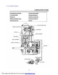
4. LUBRICATION SYSTEMSERVICE INFORMATION ··· 4-1TROUBLE SHOOTING···· 4-1ENGINE OIL LEVEL CHECK·····4-2REPLACEMENT OF ENGINE OIL·· 4-3OIL FUMP·········· 4-3TRANSMISSION OIL·······4-5SERVICE INFORMATIONWARNING•The exhaust gas contains poisonous substance. Do not keep engine idling in a closed or poorly ventilated place fora long time.•Used engine oil may cause skin cancer if repeatedly left in contact with the skin for prolonged periods.•It is not desirable to handle used oil frequently ; however, wash your hands thoroughly with soap and waterimmediately after handling the used oil.•The oil pump can be serviced without removing the engine from the frame.ENGINE OILOIL CAPACITYat disassemblingat changingRECOMMENDED OILUse appropriate type of oil with viscocity satisfying the atmospheric temperature.In your riding area based on the table shown on the right sideTemperature to the airTRANSMISSION OILOIL CAPACITYRECOMMENDED OILFull capacityat changingDAELIM Geguine mission oil or SAE 80W/90TORQUE VALUESTAPPET ADJUSTING HOLE CAPOIL PUMP BOLTOIL DRAIN PLUG BOLT1.5kgf·m1.1kgf·m2.5kgf·m
LUBRICATION SYSTEMTROUBLE SHOOTINGOil level low●Natural oil consumption●External oil leaking●Worn piston ring or incorrect piston ring installation●Worn valve guide or valve stem sealOil contamination●Oil or filter not changed often enough●Faulty cylinder head gasket●Piston ring wornLow or no oil pressure●Clogged oil filter screen●Incorret oil used
LUBRICATION SYSTEMOIL LEVEL GAUGEAPPROPRIATE LINEENGINE OIL LEVEL CHECK● Erect the motorcycle on the main stand.● Start the engine and let it be warm fully.● Stop the engine, remove the oil gauge● Check the oil level line. If the engine oil isinsufficient, add the engine oil.UPPERLOWERENGINE OIL CHANGENOTE•Make the engine warm and erect the motorcyclewith side stand in order to assure complete andrapid draining.OIL DRAIN BOLT HOLE● Loosen the drain oil bolt and drain the engine oil.● Start the kick starter arm for several times to drainany oil which may be left in the engine.● Tighten the engine oil drain bolt.TORQUE : 2.5 kgf·mTAPPET ADJUSTING HOLE CAPOIL FELTER SCREENCAUTION•It is extremely important to replace oil filter orclean the oil filter screen at the first maintenanceinterval 500km by loosen the tappet adjust holecap.•Clean the oil filter screen with fresh cleaning oilevery 4,000km.•Check the hole cap o-ring for satisfactorycondition.•If there are not in good condition, replace it withnew one.•Tighten the hole cap with specified torque.TORQUE : 1.5 kgf·mOIL LEVEL GAUGE● Fill the recommended engine oil with engine oil cap.OIL CAPACITY : 0.85 L (After disassembly)0.70 L (After oil change)● Tighten the oil level gauge.● Recommended engine oil :DAELIM genuine oil.API service classification SL gradeViscosity : 10W-40● Start the engine and let it idle for a few minutes.● Stop the engine and check the engine oil level. If theoil level is low, add the recommended engine oil.● Check to see if the oil is leak..
LUBRICATION SYSTEMOIL PUMPINSPECTION● Drain the engine oil.● Untie 1 flange bolt and 2 tapping screws installed atcooling fan cover.COOLING FAN COVERHEX BOLTAC GENERATOR● Disassemble cooling fan.● Disassemble AC generat.FRANGE BOLTRH. CRANK CASE COVER● Disassemble RH. Crank case cover.● Untie hex nut installed at oil pump drive gear.● Untie oil pump drive gear.HEX NUTOIL PUMP DRIVE GEARFLANGE BOLT● Untie 3 fixed flange bolts at oil pump.● Untie oil pump..OIL PUMP
LUBRICATION SYSTEMOUTER ROTORPUMP BODYINNER ROTORDRIVE GEAROIL PUMP DISASSEMBLY● Loosen the screw securing the oil pump plate.● Remove the oil pump body and oil pump plate.● Clean the oil pump body, inner rotor, outer rotor withfresh cleaning oil.PUMP SHAFTPUMP PLATEFEELER GAUGEPUMP BODYOIL PUMP INSPECTION● Install the inner and outer rotors into the oil pumpbody exactly.● Measure the end clearance pump body and outerrotor.SERVICE LIMIT : 0.2 MMTOOL : FEELER GAUGEOUTER ROTOR● Measure the end clearance between inner and outerrotor.SERVICE LIMIT : 0.18 MMINNER ROTOROUTER ROTOR● Measure the pump side clearance and multi sides ofrotor.SERVICE LIMIT : 0.12 MMFEELER GAUGRE
LUBRICATION SYSTEMASSEMBLY● Clean all parts with fresh cleaning oil.● Install the inner and outer rotors into the oil pumpbody.FAN SCREWS● Install the oil pump plate into the pump body.● Tighten the fan screw.NOTE•Check the oil pump to operate smoothly by turningpump shaft.INSTALLATION● Assemble o-ring and dowel pin.● Assemble oil pump to RH. Crank case.OIL RINGS● Assemble the following parts- Oil pump drive gear- RH. Crank case cover- A.C. Generator- Cooling fan and cooling fan cover- Muffler
LUBRICATION SYSTEMTRANSMISSION OILINSPECTION● Check the connection part of case for any leak.● Loosen the oil check bolt and check to see if the oiloverflows from the oil check hole.● If the oil amount is not enough , loosen the oil checkbolt and fill the recommended transmission oil to theoil filter hole.OIL CAPACITY : 0.12 L (After disassembly)0.10 L (After oil change)OIL DRAIN BOLTOIL CHECK HOLEOIL CHECK HOLECAUTION•Oil level inspection must be performed in the flatground with the vehicle being straight by raisingthe main stand.RECOMMENDED OIL : SAE 80W/90● Tighten the oil check bolt.TORQUE : 0.9 kgf·m● Start the engine and check for leak.OIL DRAIN BOLT
MEMO
5. FUEL SYSTEMSERVICE INFORMATION ·· 5-1TROUBLESHOOTING···· 5-2FUEL TANK········ 5-3CARBURETOR·······5-3CARBURETOR INSULATOR· 5-6PILOT SCREW ADJUSTMENT·5-9FUEL COCK········5-11SERVICE INFORMATIONGENERAL SAFETYCAUTION● Gasoline is extremely flammable. Avoid fire in the work place, also paying particular attention to sparks.Furthermore the evaporated(gasfied) gasoline is highly explosive. Work in a well-ventilated areas.● Exhaust gas contains poisonous substance. Do not keep engine running for a long period of time in a closed, orpoorly ventilated area.● Do not excessively bend or twist cable. Distorted or damaged cable may lead to mechanical malfunctions.● Pay particular attention to the position of O-ring. Replace with new ones when disassembled.● If it is desired to store a vehicle for a period longer than 1 month, drain gasoline out of the carburetor float chamber.Gasoline left in the float chamber will be deteriorated causing the slow jet to be cloggedwith deposits, and idlingmay become unstable.SPECIFICATIONSFUEL TANK CAPACITY : 5.0lRESERVE FUEL CAPACITY : 1.5lCARBURETOR SPECIFICATIONSITEMTYPE/ VENTURI DIAMETERMODEL MARKMAIN JET NO.PILOT SCREW REVERSE-ROLLINGFLOAT LEVELIDLING SPEEDTHROTTLE GRIP TOLLERANCESTANDARDSCV TYPE(VACUUM)/16PD 19J#8021/211mm1,700100rpm2-6mmTOOLFLOAT LEVEL GAUGE
FUEL SYSTEMTROUBLESHOOTINGThe vehicle does not start.● No gasoline in fuel tank.● Fuel is not coming out of carburetor.● Too much fuel is flowing into cylinder.● No spark emitted from spark plug.● Air cleaner is blocked.Idle is unstable and engine turns off after starting.● Idle is adjusted improperly.● Air/fuel mixture is either too lean or rich.● Air cleaner is blocked.● Suction system is experiencing secondary intake of air.● Fuel system is blocked.● Auto bystarter is damaged.● Ignition system is damaged.● Using low quality gasoline.● Air screw is adjusted improperly.● Carburetor is blocked.● Compression pressure is low.Back firing● Ignition system is damaged or works improperly.● Mixture is too lean.Insufficient power and high fuel consumption.● Air cleaner is blocked.● Ignition system is damaged.● Mixture is too rich.Air/Fuel mixture is extremely lean● Jets of carburetor are blocked.● Bad ventilation of air in tank cap.● Fuel strainer screen is blocked.● Fuel tube is bent, creased or blocked.● Float valve is working badly.● Oil level is low.● Suction system is receiving secondary suction of air.● Output capacity of fuel pump is insufficient..Miss-fire at speeding.● Ignition system is damaged.● Mixture is too lean.Air/Fuel mixture is extremely rich.● Float valve is damaged.● Air jets are blocked.● Oil level is too high.● Auto bystarter is damaged.● Air cleaner is blocked.
FUEL SYSTEMFUEL TANKREMOVAL● Remove luggage box.● Untie 4 flange bolts installed at fuel tank.FRANGE BOLT● Remove the fuel unit wire coupler.● Remove the tube located fuel tank and fuel filter.● Remove the fuel tank joint pipe tube.CAUTION•Gasoline is extremely flammable. Avoid fireduring work and pay particular attention to electricsparks.Furthermore, the evaporated(vaporized)gasoline is highly explosive. Work in a wellventilatedareas.FUEL UNITNOTE•After removing the fuel tank, be sure to close thefuel tank cap. (Gasoline is extremely flammable.)● Remove fuel tank.● Install in the reverse order of removal.FUEL TANKCARBURETORREMOVAL● Disassmeble luggage box.● Untie screws installed at air cleaner.● By untieing throttle cable lock nut, disconnectthrottle cable from carburetor.● Disconnect fuel tube from carburetor.● Disconnect auto by starter wires.SCREWCARBURETOR
FUEL SYSTEM● Untie screws installed at insulator.● Disconnect carburetor.CARBURETORTOP SETREMOVAL● Loosen the drain screw and drain the fuel.● Remove the drain tube and air band hose.● Loosen the 2 diaphragm cover setting screws.FAN SCREWSCOMPRESSION SPRING● Disconnect top set cover..VACUUM PISTONTOP SET● Disconnect jet needle, spring seat from vacuumpiston.VACUUM PISTON
FUEL SYSTEMVACUUM PISTONJET NIDDLE COMPINSPECTION● Check the jet needle for wear and replace ifnecessary.● Check the vacuum piston for damage and replace ifnecessary.● Check the diaphragm for damage, pin holes, bendsand replace if necessary.SPRING SEATNOTE•Check the diaphragm adequately for crack in thewrinkled and bent area.● Loosen 3 screws from float chamber set.ACCELERATION PUMPFLOAT CHAMBER SETFLOAT● Loosen screw at float pin.● Disassemble float pin, float, float valve.CAUTION•Do not damage the jets because it made of softmaterial and also, do not use the wire whencleaning the air and fuel passage.•Otherwise, it will damage to the carburetor body,eventually it will be effect the engine. Namely it iscause of bad condition of engine.FLOAT PINFLOAT VALVE● Check the float and valve seat for scores, scratches,clogging and damage replace if necessary.● Check the float valve operation.
FUEL SYSTEMSLOW JET● Remove the main jet, main jet holder, needle jet,slow jet, pilot screw.MAIN JETCLEAN COMPRESSED AIR● Clean the all jet and hole of carburetor body withblow the compressed air.CAUTION•Turn in the pilot jet screw and record the numberof turns it takes before it seats lightly.•Do not force pilot screw against its seat. The seatwill be damaged.
FUEL SYSTEMCOVERCOMPRESSIONSPRING● Disassemble accelerating pump.● Loosen 2 screws, disconnect diaphragm,compression spring.● Check whether there are pin role, twist, damage ofdiaphragm.● Clean by compressed air fuel channel of diaphragmcover.DIAPHRAGM COMPASSEMBLY● Assemble needle jet, needle jet holder, main jet,slow jet..● Assemble O-ring washer of pilot screw, springscrew.● Assemble based on revultion point remembered atthe time of disassembling pilot screw.● Measure float level.FLOAT LEVEL : 11MMTOOL : FLOAT LEVEL GAUGECAUTION•Replace with new float chamber body o-ring.● Assemble float valve, float, float pin.● Assemble float body ass’y and 3 fan screws,bracket.
FUEL SYSTEM● Assemble accelerating pump.CAUTION•Assemble jet neeld fitting at assembled hole.TOM SET● Assemble vacuum piston, jet needle, spring seat.● Assemble compression spring.● Assemble tom set and install 2 screws.CAUTION•Be careful for vaccum piston not to pinch to tomset.•By keeping spring straight and reducing its length,assemble cover.COMPRESSION SPRINGINSTALL● Install carburetor to carburetor insulator.● Assemble carburetor fixed type insulator bandscrew.● Assemble fuel tube to carburetor.● Assemble auto bystarter wires.● Assemble throttle cable to carburetor.● Assemble air cleaner.● Assemble luggage box.● Assemble center cover.CAUTION•Check throttle grip tolerance after assemblingcarburetor.
FUEL SYSTEMINSULATORCARBURETOR INSULATORDIASSEMBLY● Disassemble luggage.● Disassemble carburetor.● Disassemble floating pressure fuel pump.● Disassemble 2 fixed nuts of inlet pipe.● Disassemble carburetor insulator.● Disassemble fixed band of carburetor insulator.INLET PIPEINSPECTION● Check abrasion or damage of carburetor insulator.● Check abrasion or damage of inlet pipe o-riing.● Install in the reverse order of removal.INSULATORINLET PIPEPILOT SCREW ADJUSTMENTUSING THE EMISSION ANALYZER(CO,HC)● Open the seat and remove the carburetormaintenance cover. Turn the pilot screw clockwise until it seats lightly,then back it out to the specification given.(21/2) up the engine to operating temperature(60°C). Adjust the idle speed with the throttle stop screw.PILOT SCREWIDLE SPEED: 1700 °±100 RPMMUFFLERCO ANALYZERNOTE•Before adjustment the pilot screw, check thefollowing items.•Fuel system electrical system for troubling.•Do not force the pilot screw against its seat. Theseat will be damaged.•The spark plug for cleaning and gap adjusting.•Valve clearance for adjusting.•Emission analyzer for correction.•Exhaust gas contains poisonous substance, so donot•adjusting in a closed or poorly ventilated area.
FUEL SYSTEMTHROTTLE STOP SCREW Extend the hose(60mm) at the tail pipe and insert theprobe of the emission analyzer to the tail pipe andadjust the pilot screw with a 1/8, the Co to became3~4%. Adjust by the throttle stop screw, repeat step and until according the idle rpm (1,700rpm) and theCo(3~4 %). Snap lightly in idling and check to see if the rotationis smoothly and to return is normal.● Install the carburetor maintenance cover.ACCELERATINGNOTE•If the engine cannot be adjusted by turning thepilot screw within a ¼ turn, check for other engineproblems.EMISSION ANALYZER IS NOT EXIST Turn the pilot screw clockwise until its seats lightly,then back it out to the specification given. (1 1/2) Warm up the engine until the engine oil temperaturereaches to approximately 60°C. Adjust the idle speed with the throttle screw.IDLE SPEED: 1700 °±100 RPMPILOT SCREWNOTE•Before adjustment the pilot screw, check thefollowing items.•Fuel system electrical system for troubling.•Do not force the pilot screw against its seat. Theseat will be damaged.•The spark plug for cleaning and gap adjusting.•Valve clearance for adjusting.THROTTLE STOP SCREW
FUEL SYSTEMACCELERATING When idling, check to see if the rotation is smoothlyand to return is normal. Turn the throttle stop screw until the 1000 rpm, andcheck the stopping of engine.If the engine is stop, adjust the pilot screw with a 1/8and repeat step and (Check by snapping slightly and check whetherRPM goes down naturally.)NOTE•If the engine cannot be adjusted by turning thepilot screw within a ¼ turn, check for other engineproblems. After the final test of the starting and driving,readjust if necessary. Assemble the carburetormaintenance cover of luggage box.PILOT SCREWTHROTTLE STOP SCREW● Assemble luggage box to carburetor maintenancecover.FUEL STRAINERFUEL COCKFUEL COCK● Disassemble luggage box.● Disconnect fuel tube A, B connected to fuel cock.● Disassemble fuel cock.● Install in the reverse order of removal.INSPECTION● Be sure to remove the diaphragms from the fuel autovalve before using compressed air the blow out ofair passages. Compressed air will damage thediaphragms or may forced them off the aluminum.FUEL COCKAIR VENTFLOATINGPRESSURELINELINKSPRINGSMALLDIAPHRAGMLARGEDIAPHRAGMNOTE•Place a clean container under the fuel tube.● Do repair after emptying gasoline in fuel tank.● Connect the fuel auto valve vacuum tube to thevacuum pump and apply vacuum. Be sure that thefuel flows out smoothly.● If the vacuum does not remain steady, it indicatesthe diaphragm is incorrectly installed or damaged.● If the vacuum remains steady, but the fuel flow isnot smooth, it indicates a clogged filter orincorrectly installed diaphragm.● If the fuel flows without the vacuum applied, thediaphragm is incorrectly installed.
MEMO
6. ENGINE REMOVAL/INSPECTIONSERVICE INFORMATION····· 6-1ENGINE REMOVAL/ASSEMBLY·· 6-2SERVICE INFORMATIONGENERAL SAFETYNOTE•Use a jack to remove or install the engine. Support the motorcycle with a jack firmly, taking precautions not todamage the frame, engine, cable or harness.•Attach tape to the frame to protect it during the engine removal or installation.● The following works can be carried out without removing the engine from the vehicle body.-TRANSMISSION (⇨SECTION 11)-A.C. GENERATOR (⇨SECTION 8)-KICK STARTER/ CONTINUOUSLY VARIABLE TRANSMISSION (⇨SECTION 7)-STATOR MOTOR (⇨SECTION 16)-CARBURETOR (⇨SECTION 5)-EX. MUFFLER (⇨SECTION 3)● Items to be worked after removing engine.-CYLINDER HEAD, CYLINDER, CRANK SHAFT, CRANK SHAFT BEARING● Engine oil capacity : 0.85L(when disassembling)TORQUE VALUESENGINE HANGER BOLT : 4.5kgf·m
ENGINE REMOVAL/INSPECTIONCARBURETORENGINE REMOVAL / ASSEMBLY● Release the seat lock by turning the main key andopen the seat.● Remove the following parts.- Luggage box.- Air cleaner.- Carburetor.● Disconnect the A.C generator coupler and connectorwiring connected to the A.C generator, disconnectthe starter motor wiring cable.● Remove spark plug cap cord from the engine.● Remove the bleeder tube from the cylinder headcover.● Remove the EX. muffler.MUFFLER● Loosen the lock nut securing rear wheel and removethe rear wheel.REAR WHEELREAR CUSHION● Loosen the rear brake adjuster nut, and remove thebrake arm joint B, and remove the rear brake cable.● Remove the engine hanger nut.REAR BRAKE CABLEENGINE HANGER NUT
ENGINE REMOVAL/INSPECTION● Loosen rear cushion under bolt.REAR CUSHION UNDER BOLT● Fix the jar-key for the motorcycles to under thevehicle.● Loosen the flange bolt securing the engine hangerand remove the engine from the frame.JAR-KEYASSEMBLY● Install in the reverse order of removal.NOTE•Take precaution not to damage wiring and cable.•Take precaution not to damage the threaded part ofbolts.•Arrange the cable, tubes and wiring in the rightpositionsTORQUE : ENGINE HANGER NUT : 4.5 kgf·m● Check the following after the engine is installed.- Engine oil leakage.- Inspection of throttle cable operation.
BELT TYPE CONTINUOUSLY VARIABLE TRANSMISSION / KICK STARTER
7. BELT TYPE CONTINUOUSLY VARIABLETRANSMISSION / KICK STARTERSERVICE INFORMATION···7-1SERVICE STANDARD···· 7-1TROUBLESHOOTING···· 7-1LH. CRANK CASE COVER REMOVAL· 7-2KICK STARTER· · · · · · 7-2DRIVE BELT········7-4DRIVEN PULLEY ASS’Y· · · · 7-6MOVABLE DRIVE FACE· · · 7-11SERVICE INFORMATIONGENERAL SAFETY● Do not allow oil to contact the drive belt or the pulley face. The transmission rate of driving force is reduced due tooil contact.● Do not operate starter motor while the LH. crank case front cover is removed.NOTE·Take precautions not ot apply the grease oil to the movable drive face or weight roller.SPECIFICATIONSITEM STANDARD SERVICE LIMITMOVABLE DRIVE FACE BUSHING INNER DIAMETER 20.000~20.021mm 20.10mmDRIVE FACE BOSS OUTER DIAMETER 19.959~19.980mm 19.91mmDRIVE BELT WIDTH 17.5mm 16.5mmWEIGHT ROLLER OUTER DIAMETER 15.920~16.080mm 15.40mmCLUTCH OUTER AND INNER DIAMETER 107.000~107.087mm 107.50mmTROUBLESHOOTINGEngine starts but motorcycle does not work.● Drive belt worn.● Ramp plate damaged.● Clutch shoe worn or damaged.● Movable driven face spring cut.Engine stops, or the vehicle runs suddenly,after starting.● Clutch shoe spring cut.Vehicle unable to run at the maximum speed,or lack of output● Drive belt worn.● Defective movable driven face spring.● Weight roller worn.● Pulley face contaminated.
BELT TYPE CONTINUOUSLY VARIABLE TRANSMISSION / KICK STARTERLH. CRANK CASE COVERREMOVAL● Loosen 10 flange bolts assemble at LH. Side cover.KICK STARTER ARMDOWEL PIN● Disassemble LH. Side cover.● Disassemble gasket and dowel pin.GASKET● Inspect LH. crank case cover.● Install the new gasket and dowel pin after removingthe gasket of crankcase surface.● Install in the reverse order of removal..NOTE·When not knowing the length of bolt, arrangeassembled positions regularly before assembling it,then assemble it.·When assembling bolts, assemble them diagonallybased on standard specification assembly torques.KICK RETURN SPRINGKICK DRIVEN GEARKICK STARTERDISASSEMBLE● Disassemble LH. Side cover.● Disassemble fixed flange bolt of kick starter arm.● Disassemble kick starter arm.● Disassemble external circlip 14mm.● Disassemble kick starter spindle washer.● Disassemble kick starter spindle.● Disassemble kick starter spindle spring.● Disassemble kick starter spindle bush.KICK STARTER SPINDLE
BELT TYPE CONTINUOUSLY VARIABLE TRANSMISSION / KICK STARTERCIR CLIPKICK SPINDLE BUSHKICK SPINDLE WASHERCHECK● Check whether kick starter spindle worn, damageand gears worn, damage.● Check whether return spring defect or damage.● Check whether kick starter spindle bushing worn ordamage.KICK STARTER SPINDLEKICK SPINDLE BUSH BKICK RETURN SPRINGKICK DRIVEN GEAR● Check kick driven gear worn, damage.● Check friction spring defect, damage.PRICTION STARTGEAR SPRINGTHRUST WASHERKICK SPINDLE BUSH BASSEMBLY● Assemble kick spindle bush to LH. Side cover.● Assemble kick spindle bush B to LH. Side cover.● Assemble kick spindle spring to LH. Side cover.● Assemble kick spindle to LH .Side cover.● Assemble kick starter spindle washer.● Assemble cir clip 14mm to LH. Side cover.● Assemble kick starter arm.● Assemble thrust washer.KICK SPINDLE BUSHKICK RETURN SPRING● Turn kick starter spindle by kick starter arm, thenassemble gear on condition of pulling ‘’ of LH.Side cover.KICK STARTER SPINDLEKICK DRIVEN GEARCAUTION·Assemble correctly kick starter spindle to the homeby fixing using hand.·Apply grease into gear side and assemble home ofkick driven gear.·Check whether kick driven gear and kick starterspindle work well after assembly.
BELT TYPE CONTINUOUSLY VARIABLE TRANSMISSION / KICK STARTERDRIVE FACEDRIVEN PULLEY ASSYDRIVE BELTREMOVAL● Disassemble LH. Side cover. (⇨7-2)● Disassemble 2 dowel pins and gasket.DRIVE BELTCAUTION·Be careful for missing of dowel pin. Whendisassembling gasket, be careful its torn.STARTER PINION● Diassemble start pinion ass’y in order to do easyrepair.CLUTCH OUTER● Install special tool(universal holder) to clutcu outer,Then disassmble 10 mm nut● Disassemble clutch outer.DRIVE FACEDRIVE BELT● On condition that drive belt is assembled at drivenpulley sub, extract to the outside of drive face.● Disassemble belt from driven pulley sub.DRIVEN PULLEY SUB
BELT TYPE CONTINUOUSLY VARIABLE TRANSMISSION / KICK STARTERCOGWIDTHINSPECTION● Check the drive belt for cracks, cog seperation andwear ; Replace as necessary.● Measure the width of the drive belt replace thebelt if the service limit is exceeded.SERVICE LIMIT : 16.5mmNOTE·Use only a genuine DAELIM replacement drivebelt.·Do not get oil or greasde on the drive belt or pulleyside.·Clean off any grease or oil before reinstalling.DRIVEN PULLEY SUB ASSYINSTALLATION● Like left pucture, turn the pulley clockwise andspread the faces apart while installing the drive belt.NOTE·Hold the pulley faces apart preventing them fromclosing.● Hang on drive belt assembled at driven pulley subass’y.● Between drive face and movable drive face, thenassemble it to drive shaft in reverse side.DRIVEN PULLEY SUB ASSY● Assemble clutch outer to driven pulley sub ass’y.● Temporarily install flange nut 10mm to driven pulley,tighten the nut to the specified torque.TORQUE : 4.OkgfmTOOL : UNIVERSAL HOLDER
BELT TYPE CONTINUOUSLY VARIABLE TRANSMISSION / KICK STARTERDRIVEN PULLEY ASS’YREMOVAL● Remove the LH. crank case cover. (⇨7-2 )● By using universal holder, grip clutch outer anddiassemble flange nut, then disassemble clutch outer.TOOL : UNIVERSAL HOLDERDRIVE FACE HOLDER● Disassemble driven pulley ass’y from drive shaft.● Disassemble drive belt.SPECIAL NUTCLUTCH SPRING COMPRESSORDISASSEMBLY● Disassemble special nut 28mm.TOOL : CLUTCH SPRING COMPRESSORLOCK NUT WRENCH● Disassemble drive plate ass’y.● Disassemble driven face spring.● Disassemble driven face spring guide.DRIVE PLATEDRIVEN FACE SPRINGMOVABLE DRIVEN FACESPRING GUIDE
BELT TYPE CONTINUOUSLY VARIABLE TRANSMISSION / KICK STARTERDRIVEN FACE COMP● Disassemble seal collar.SEAL COLLARMOVABLE DRIVEN FACE● Pull out roller guide pin and guide roller.GUIDE PINDRIVEN FACEMOVABLE DRIVEN FACE● Pull out movable driven face.● Disassemble O-ring from movable driven face.● Disassmeble oil seal from movable driven face.DRIVEN FACEGUIDE PINOIL SEALMOVABLE DRIVEN FACE● Disassemble movable driven face.
BELT TYPE CONTINUOUSLY VARIABLE TRANSMISSION / KICK STARTERNIDDLE BEARING (INNER)BALL BEARING (OUTER)INSPECTION● Check each part● Check driven face needling bearing(inside) fordamage or excessive play and replace necessary.Turn the inner race of the outer bearing with yourfinger. Check that the bearing turns smoothly andquietly, and that the bearing outer race fits securely.MOVABLE DRIVEN FACE SPRING● Measure the free length of the driven pulley springand replace if the service limit is exceeded.SERVICE LIMIT : 163.7MMFREE PLAY● Check worn or damage of clutch outer.● Measure the inner diameter of clutch outer.SERVICE LIMIT : 107.5MMCLUTCH OUTER● Check damage or worn of clutch shoe.● Measure the thickness of each shoe.● Replace if the service limit is exceedede.SERVICE LIMIT : 1.5 MMCLUTCH SHOE
BELT TYPE CONTINUOUSLY VARIABLE TRANSMISSION / KICK STARTER● Check damage or worn of movable drive face.● Check whether worn of movable driven face guidehome.● Measure inner diameter of movable driven face.SERVICE LIMIT : 34.06MMMOVABLE DRIVEN FACE● Check worn or damage of driven face.● Measure outer diameter of driven face.SERVICE LIMIT : 33.94MMDRIVEN FACEOUTER BEARINGSNAP RINGINNER BEARINGINNER BEARINGREPLACE DRIVEN FACE BEARING● Replace inner bearing.● Remove snap ring, disassemble outer bearing to theside of inner bearing.● Assemble new replacement outer bearing.● Assemble snap ring.● Apply grease to the designated position of right sidepicture.APPLYING GREASE CAPACITY : 9.0~9.5g● Assemble new replacement inner bearing.SEAT SIDEGREASEAPPLYINGRANGESNAP RINGNOTE•Assemble completely cir clip to the home.•Input inner bearing by press.TOOL : Bearing driver attachmentDriver pilotINNER BEARING(NEEDLE)OUTER BEARING
BELT TYPE CONTINUOUSLY VARIABLE TRANSMISSION / KICK STARTERMOVABLE DRIVEN FACEASSEMBLY● Assemble oil seal, o-ring to movable driven face.● Assemble movable driven face to driven face.● Assemble guide roller and roller pin.DRIVEN FACEGUIDE PINMOVABLE DRIVEN FACE● Assemble movable driven face to driven face.● Assemble guide roller and roller pin.SEAL COLLAR● Assemble seal collar.LOCK NUT WRENCHASSEMBLY● Assemble spring guide and drive face, drive plateass’y.● Compress special nut 28mm to be assembled byclutch spring compressor● Fix clutch spring compressor like right picture,assemble lock nut based on designated torque byusing lock nut wrench.● Remove spring compressor.TORQUE : 5.5kgf·mTOOL : LOCK NUT WRENCHCLUTCH SPRING COMPRESSOR
BELT TYPE CONTINUOUSLY VARIABLE TRANSMISSION / KICK STARTERDRIVEN PULLEY SUBDRIVEN PULLEY ASSEMBLY● Turn right driven pulley ass’y and widenmaximumly assembled home for belt● Assemble drive belt to drive pulley sub ass’y, thenassemble to drive shaft.DRIVEN PULLEY● Assemble clutch outer to driven pulley sub ass’y,assemble temporarily special flange nut.● After fixing clutch outer to universal holder, thenfasten flange nut 10mm as the specified torque.TORQUE : 4.0kgf·mTOOL : UNIVERSAL HOLDER● Assemble LH. Side cover.DRIVE FACEMOVABLE DRIVE FACEREMOVAL● Disassemble LH. Side cover.● Disassemble start pinion ass’y.● Hold the drive face using the clutch center holderand remove hex nut 12mm and drive face.TOOL : DRIVE FACE
BELT TYPE CONTINUOUSLY VARIABLE TRANSMISSION / KICK STARTERCVT COOLING FAN● Disassemble kick starter rachet.● Disassemble CVT cooling fan.● Disassemble drive face.● Disassemble drive face boss.● Disassemble movable drive face.KICK STARTER RATCHETINSPECTION● The weight rollers push on the movable driveface(by centrifugal force).● Worn or damaged weight rollers will interfere withthis force, is a reason of bad working of drive face.LAMP PLATEWEIGHT ROLLERDRIVE FACE BOSS● Damage or side worn of weight roller replace● Measure outer diameter of weight roller.SERVICE LIMIT : 15.4MM● Measure inner diameter of movable drive face.SERVICE LIMIT : 20.1MMDRIVE FACE BOSS● Measure outer diameter of movable drive face boss.SERVICE LIMIT : 19.91MM● Damage or worn of movable drive face boss replace.MOVABLE DRIVE FACE
BELT TYPE CONTINUOUSLY VARIABLE TRANSMISSION / KICK STARTERKICK STARTER RATCHET● Check drive face.● Check worn or damage of CVT cooling fan.DRIVE FACECVT COOLING FANASSEMBLY● Assemble weight rollers to movable drive face.● Assemble lamp plate.LAMP PLATEWEIGHT ROLLERNOTE•Do not apply grease to the pulley side of movabledrive face- If done, clean it.● Assemble movable drive face boss and movabledrive face to LH. Crank shaft.● Assemble drive belt to crank shaft.RATCHET● Assemble drive face.● Assemble CVT cooling fan and rachet.
BELT TYPE CONTINUOUSLY VARIABLE TRANSMISSION / KICK STARTER● Assemble drive face to the serration side of LH.Crank shaft, then assemble hext nut 12mm.FLANGE NUT● By using drive face holde, fasten drive face nut.TORQUE : 5.5kgf·mTOOL : DRIVE FACENOTE•Assemble drive pulley nut as specified torque.•Assemble by completely fitting drive face andcrankshaft sereration.•Fix fly wheel to universal holder if drive pulleyholder can not be used.● Assemble 2 dowel pins and gasket● Assemble LH. Side cover .7-14
MEMO
A.C. GENERATOR /RH. CRANK CASE COVER
8. A.C. GENERATOR /RH. CRANK CASE COVERSERVICES INFORMATION········8-1COOLING FAN COVER··········8-2AC GENERATOR·············8-4RH. CRANK CASE COVER········8-4SERVICE INFORMATIONGENERAL SAFETY● This section describes the removal and assembling of the A.C. generator.● For the information of A.C. generator inspection, refer to the section 15.● The charging systme can be maintained without removing the engine.TORQUE VALUESFLY WHEEL NUTRH. CRANK CASE COVER BOLT5.5kgf·m1.0kgf·mTOOLA.C.G. ROTOR PULLER
A.C. GENERATOR /RH. CRANK CASE COVERCOOLING FAN COVERCOOLING FAN COVERREMOVAL● Remove the muffler.● Loosen the 1 tapping screws and 2 flange boltssecuring the cooling fan.UPPER HOODCOOLING FAN● Upper hood and low hood can be remove afterremoving the engine from the frame.LOW HOODFLY WHEELA.C GERNERATORREMOVAL● Remove the cooling fan cover.● Remove the cooling fan.FLY WHEEL● Install the universal holder on flywheel.● If the universal holder cannot be used, remove theLH. crankcase cover at the left side of crankshaftand hold the drive face with the drive face holder.● Untie hex nut 12mm.UNIVERSAL HOLDER
A.C. GENERATOR /RH. CRANK CASE COVER● Loosen the flange nit securing the fly wheel andremove the flywheel using the A.C.G. rotor puller.ACG ROTOR PULLERHEX BOLTACGCAUTION•The flywheel may easily remove if you rotate thepuller while tapping the roller shaft metal hammer.•Always use a holder and a puller to remove theflywheel. Do not try to remove the flywheel byhammering directly on it. The crank shaft orcomponents could be damaged.•After disassembling fly wheel, check whetherwoodruff key damaged or not.FLANGE BOLTTOOL: A.C.G ROTOR PULLERUNIVERSAL HOLDERDRIVE FACE HOLDER● Loosen the 2 flange bolts securing stator andremove the stator.● Loosen the 2 bolts securing the pulse generator andremove it.DISASSEMBLE● ACG wire coupler and connecter connected withwire harness.ASSEMBLY● Assemble ACG stator to RH. crank case cover.● Clean crank shaft taper side.● Clean the inside of fly wheel.● Check woodruff key, assemble the home of fly wheelto woodruff key.
A.C. GENERATOR /RH. CRANK CASE COVER● If the universal holder cannot be used, remove theLH.crankcase cover at left side of the crankshaft, andhold the drive face with the drive face holder.TORQUE : 5.5kgf·mTOOL : UNIVERSAL HOLDER● Assemble cooling fan.(⇨8-2 )● Assemble ACG. cord coupler and connector at wireharness, and cramp cords.● Assemble cooling fan cover.COOLING FANRH. CRANK CASE COVERREMOVAL● Disassemble the following parts.- Muffler- Cooling fan cover- Cooling fan● Remove engine oil.● Untie 8 flange bolts assembled at RH. Crank casecover.● Disassemble RH. Crank case cover.RH.CRANK CASE COVER
A.C. GENERATOR /RH. CRANK CASE COVERDOWEL PIN● Pull out gasket and dowel pin.OIL PUMP REDUCTION GEAR● Check worn or damage of oil seal, if necessary,replace with the new oil seal.● Disassemble RH. Crank case cover oil seal andreplace with the new one.OIL SEALASSEMBLY● Assemble RH. Crank case cover.● Assemble AC Generator.● Assemble muffler.NOTE•Assemble completely by fitting correctly to thehome.● Assemble fly wheel.● Assemble cooling fan.● Assemble cooling fan cover.
CYLINDER HEAD / VALVES
9. CYLINDER HEAD / CYLINDER / PISTONSERVICE INFORMATION ···9-1TROUBLE SHOOTING ····· 9-2CAM SHAFT········· 9-3CYLINDER HEAD·······9-5VALVE SPRING········ 9-6IN / EX VALVE ········9-6VALVE GUIDE········ 9-7VALVE SEAT·········9-8IN / EX VALVE ASSEMBLY·· 9-8CYLINDER HEAD ASSEMBLY· 9-10CAM SHAFT ASSEMBLY··· 9-10SERVICE INFORMATIONGENERAL SAFETY● The rocker arm and the camshaft can be served without removing the engine.● The oil of camshaft is supplied through the cylinder head oil hole.● Clean th oil hole prior to assembling the cylinder head.SPECIFICATIONSUNIT ITEM STANDARD VALUE SERVICE LIMITROCKER ARM INNER DIAMETERROCKER ARMROCKER ARM OUTER DIAMETERCAM SHAFTCAM HEIGHTINEXCYLINDER HEAD WARFAGEVALVE SPRING FREE LENGTHVALVEVALVE GUIDEVALVE STEM OUTERDIAMETERVALVE GUIDE IN. DIAMETERCLEARANCE BETWEENSTEM AND GUIDEININEXIN, EXINEXVALVE SEAT WIDTHTORQUE VALUESSPARK PLUGCAM SHAFT HOLDER 7mm NUTCAM CHAIN TENSIONER BOLTCAM CHAIN TENSIONER SEALING BOLTCYLINDER HEAD COVER BOLTCYLINDER HEAD BOLTTAPPET ADJUST NUT1.2kgf·m2.0kgf·m1.1kgf·m0.4kgf·m1.1kgf·m1.2kgf·m1.1kgf·m
CYLINDER HEAD / VALVESTOOL-VALVE GUIDE REAMER-VALVE GUIDE DRIVER-VALVE SPRING COMPRESSORTROUBLESHOOTING● Engine top-end problems usually affect engine performance. These can be diagnosed by a compression or leak downtest or by tracing noises to the top-end with a sounding rod or stethoscope.Low compression● Valves- Incorrect valve adjustment- Burned or bent valve- Incorrect valve timing- Broken valve spring- Uneven valve seating● Cylinder head- Leaking or damage head gasket- Warped or cracked cylinder head● Cylinder head defectExcessive smoke● Worn valve guide or valve stem● Damaged valve stem seal● Worn or damaged piston ringRough idle● Low cylinder compressionCompression too high● Excessive carbon built-up on piston or combustion chamberExcessive noise● Incorrect valve adjustment● Sticking valve or broken valve spring● Damaged or worn camshaft● Worn rocker arm and / or shaft● Loose or worn cam chain● Worn or damaged cam chain tensioner● Damaged cylinder head gasket● Incorrect spark plug installation
CYLINDER HEAD / VALVESCYLINDER HEAD COVERFLANGE BOLTSCAMSHAFTREMOVAL● Remove the luggage box.● Remove the center cover.● Untie 4 cylinder head cover bolts.● Untie 2 SAI pipe cap nuts and cover.SAI PIPET MARKNOTE•The camshaft can be maintained without removingthe engine.● Remove the cooling fan cover.● Turn the crankshaft to the left and align the ”T”mark of the flywheel with the index mark of theRH. Crankcase cover.● Verify that the piston is located at the top deadcenter.● If all camshaft lobes face downward, rotate thecamshaft to the left for one turn(360°), and align“T” mark with the index mark once again.● Loosen the pan screw of the cam chain tensionerand remove the tensioner lifter.SPRINGFLANGE NUTSTENSIONER LIFTCAM SHAFT HOLDER● Loosen the 4 camshaft holder 7mm nuts.● Remove the camshaft holder from cylinder head.
CYLINDER HEAD / VALVESCAM SHAFTCAM CHAIN● Remove the cam chain from the cam shaft.NOTE•Take precautions not to allow the cam chain todrop into the crankcase.SHAFT● Install the 5mm bolt into the rocker arm shaft andby pulling bolt, remove the rocker arm shaft..● Remove the rocker arm.● Remove the other side rocker arm in the same order.CAM SHAFT HOLDERROCKER ARMROCKER ARMSHAFTINSPECTION● Check the rocker arm and rocker arm shaft for wearor damage.● Measure the inner diameter of the rocker arm.SERVICE LIMIT: 10.10 MM● Measure the outer diameter of rocker arm shaft.SERVICE LIMIT: 9.91 MMCAM SHAFT● Check the cam lobed of the camshaft for wear ordamage.SERVICE LIMIT: IN: 25.68MMEX: 25.52 MM
CYLINDER HEAD / VALVESBEARING● <strong>Manual</strong>ly turn the shaft bearing outer race, andcheck if it turns smoothly.● Check damage or worn of bearing, if yes, replace it.● Install in the reverse order of removal.CAUTION•Be sure to check the valve clearance.CYLINDER HEADCYLINDER HEADREMOVAL● Remove the engine(6-2).● Remove the shroud comp(upper, under hood).● Remove the cylinder head cover.● Remove the cam shaft holder.● Remove the cam shaft.● Remove the S.A.I pipe.● Remove the cylinder head.● Remove the cylinder head gasket, dowel pin andcam chain guide from the cylinder.CYLINDER HEAD GASKETSPARK PLUGREMOVAL● Remove the spark plug from the cylinder head.
CYLINDER HEAD / VALVES● Remove the valve spring compressor, valve spring,valve cotter, retainer, sparing and valve.VALVE SPRINGTOOL: VALVE SPRING COMPRESSORVALVE SPRINGCOMPRESSORNOTE•To prevent the loss of tension, do not compree thespring more than necessary.•Mark the disassembled parts so that they can bereassembled in to the original position.INSPECTION● Remove the carbon deposits from the inside ofcombustions chamber.● Check the spark plug assembling hole and the valveseat for cracks.● Using a square and a feeler gauge, check thecylinder head distortion.SERVICE LIMIT: 0.05 MMFEELER GAUGENOTE•Take precautions not to damage the cylinder headgasket attachment.AINNER VALVE SPRINGBOUTER VALVE SPRINGVALVE SPRINGINSPECTION● Measure the free length of the inner and outer valvesprings.FREE LENGTH : IN 30.5 MMEX 34.1MMNOTE•Replace the valve spring with new one if the lengthof any one is less than service limit.VALVEIN / EX VALVEINSPECTION● Inspection in/ex. valve stem for bent, seized,abnormal wear of step.● Insert the valves in their original positions in thecylinder head.● Measure and record the in/ex.valve stem outerdiameter.SERVICE LIMIT: IN 4.965EX 4.955
CYLINDER HEAD / VALVESVALVE GUIDEREAMERVALVE GUIDEINSPECTION● Insert the valve guide reamer from the combustionchamber side and ream the guide to remove anycarbon built-up before measuring the guide.NOTE•Take care to tilt or lean the reamer in the guidewhile reaming.•Rotate the reamer clockwise, nevercounterclockwise when inserting and removing.TOOL: VALVE GUIDE REAMER● Measure and record each valve guid inner diameter.SERVICE LIMIT: IN 5.04 MMEX 5.05MM● Measure the guide to stem clearance.SERVICE LIMIT: IN 0.075 MMEX 0.085 MM● Measure the inner diameter of the new valve guide.If the measure clearance is not within the servicelimit, replace the valve.VALVE GUIDEDRIVERREPLACEMENT● Heat the cylinder head to 130°C ~ 140°C.(270°F ~285°F).NOTE•Do not heat the cylinder head beyond 150°C(300°F).•Because there is burnt risk, do not unskifully work.•Do not heat locally by using of gas burner whengetting cylinder head warm.•When replacing valve guide, be sure to correctvalve seat.VALVE GUIDEDRIVER● Support the cylinder head and drive the old guidesout of the combustion chamber side of cylinderhead.NOTE•Avoid damaging the cylinder head when drivingthe valve guide out.● Install the new o-ring into the new valve guide.
CYLINDER HEAD / VALVESVALVE GUIDE REAMER● Insert the valve guide at upside of cylinder head.TOOL: VALVE GUIDE DRIVE● Insert the valve guide at upside of cylinderhead.Insert the valve guide at upside of cylinderhead.NOTE•Take care not to tilt or lean the reamer in the guidewhile reaming.•Otherwise the valve is installed slanted that causeoil leaks from the stem seal and improper valveseat contact and results in the valve seat refacingnot able to be performed.•Use cutting oil on the reamer during this operation.•Use cutting oil on the reamer during this operation.TOOL: VALVE GUIDE DRIVER● Reface the valve seats and clean the cylinder headthoroughly to remove any metal particles.EX VALVEVALVE SEATINSPECTION● Clean all the intake and exhaust valves thoroughlyto remove carbon deposits.● Apply a light coating of Prussian Blue to each valveface.● Tap the valve against the valve seat several timeswith the valve reamer, without rotating the valve tocheck for proper valve seat contact.● Remove the valve and inspect the valve seat face.● The valve seat contact should be within thespecified width and evenly all around thecircumstance.● If the valve leans, check the gap between valveguide and stem replace the valve guide if it doesn’twork well.IN VALVENOTE•Valve faces and stem tips cannot be ground. If avalve face or stem tip is rough, worn unevenly orcontacts the seat improperly, the valve must bereplaced.IN/ EX.VALVE ASSEMBLY● Install new stem seals and valve spring seat.● Lubricate each valve stem with molybdenumdisulfide grease and insert the valve into the valveguide.● Turning a valve too fast can damage the stem seals.● Check the valve for working properly with up anddown.
CYLINDER HEAD / VALVES● For valve spring with varying pitch, install the valvesprings with the narrow pitch end facing down.● Install the spring retainer.● Compress the valve springs and install the valvecotter.NOTE•Compressing the valve spring more than necessarywhen installing the valve cotters may cause loossof valve spring tension.TOOL: VALVE SPRING COMPRESSORVALVE STEM● Tap the valve stems gently with a soft hammer tofirmly seat the cotters.NOTE•Take necessary precaution not to damage the valve.SPARK PLUG● Take necessary precaution not to damage the valve.TORQUE:1.2 kgf·m
CYLINDER HEAD / VALVESCYLINDER HEADCYLINDER HEAD ASSEMBLY● Clean the gasket material from the cylinder matingsurface.● Install the cam chain guide to the cylinder.● Install the dowel pins and new gasket.● Install the cylinder head.CAMSHAFT ASSEMBLY● Apply engine to the rocker arm shaft, and assemblythe rocker arm to the camshaft holder.● Align cam shaft with the bolt hole of the camshaftholder and the fitting side of the rocker arm shaft.
CYLINDER HEAD / VALVES● Apply engine oil to the camshaft and install it on thecylinder head with the cam thread facingdownward.● Assembly the cam chain and cam sprocket aftermatching the cam sprocket timing mark in parallelwith the top pf the cylinder head.● Slowly rotate the crankshaft counterclockwise andalign the “T” mark of the flywheel with the indexmark of the RH. crank case cover.TMARKCAUTION•Take precautions not to allow the cam chain tocome off the camshaft tinning gear while turningthe camshaft.● Install the dowel pins on the cylinder head.● Assemble cam shaft holder.WASHER● Assemble washer to cam shaft holder.CAUTION•The hole of the camshaft holder and the fittingsection of rocker arm shaft fit section must be inalignment.
CYLINDER HEAD / VALVES● Install flange nut and tighten them driving with 2-3times.TORQUE : 2.0kgf·mPUSHSPRINGBOLT● Pull out spring from cam chain tensioner lifter.● Push the tensioner shaft clockwise with a smalldriver like the right picture, and insert the shaft intothe body completely.● Assemble new gasket to tensioner lifter andtensioner lift to cylinder.● Assemble flange bolt● Insert tensioner lift spring and assemble with bolt.TORQUE : 1.1kgf·mTENSIONER LIFTFEELER GAUGE● Fill the clean engine oil into the operating parts ofthe cylinder head.● Adjust the valve clearance.ROCKER ARMTAPPET WRENCH● Remove oil from the cylinder head cover groovesand accurately assemble the gasket to the cover.● Install the cylinder head cover bolts.TORQUE : 1.1kgf·m● Install the shroud comp.● Install the engine frame.
MEMO
CYLINDER / PISTON
10. CYLINDER / PISTONSERVICE INFORMATION···················10-1TROUBLESHOOTING ····················10-1CYLINDER··························10-2PISTON· ··························10-3PISTON / CYLINDER INSTALLATION··············10-5SERVICE INFORMATIONGENERAL SAFETY● Be careful not to damage the mating surfaces by using a screwdriver when disassembling the cylinder. Do not strikethe cylinder too hard during disassembly, even with a rubber or plastic mallet, to prevent the possibility of damage tothe cylinder pins.● Take care not to damage the cylinder wall and piston● Check parts after disassembling, and clean and dry with an air hose prior to taking measurements.SPECIFICATIONSCYLINDERPISTON,PISTONP I N ,PISTONRINGITEM STANDARD VALUE SERVICE LIMIT39.000-39.010mm39.04mm-0.05mm-0.05mm-0.05mm38.970-38.980mm38.92mm13.008-13.012mm13.04mm12.994-13.000mm12.98mm0.008-0.018mm0.04mmTOP0.05-0.15mm0.04mmSECOND0.05-0.17mm0.04mmINNER DIAMETERTAPEROUT-OF-ROUNDHEAD CONTACT WARPAGEPISTON SKIRT OUTER DIAMETERPISTON PIN HOLE INNER DIAMETERPISTON PINOUTER DIAMETERPISTON TO PISTON PIN CLEARANCEPISTON RING TOGROOVE CLEARANCEPISTON RINGJOINT GAPCYLINDER TO PISTON CLEARANCECONNECTING ROD SMALL END INNER DIAMETERGAP BETWEEN CONNECTING ROD SMALL END AND PISTON PINTROUBLESHOOTINGOIL RING 0.020-0.040mm13.013-13.028mm0.013-0.034mm0.08mm13.05mm0.06mmUnit : mmCompression pressure too low● Piston worn● Piston ring worn or damaged● Cylinder wornEmission of white gas from muffler● Cylinder, piston, piston rings worn● Bad adjustment of piston rings● Piston, cylinder wornOver heated● Excessive carbon built up on top of pistonAbnormal engine noise● Cylinder, piston worn● Worn connecting rod small end bearing or piston pins● Damaged piston rings● Excessive carbon built up on top of piston
CYLINDER / PISTONCYLINDERCYLINDERREMOVAL● Remove the engine from the engine.● Remove the cylinder head cover.● Remove the cam shaft holder● Remove the cylinder head.● Remove the cam chain guide from the cylinder.● Remove the cylinderCAM SHAFT HOLDER● Remove the gasket and dowel pin.● Remove any adhering gasket material from thecylinder/ head mating surface.NOTE•Take care not to damage the cylinder matingsurface.CAK CHAINCYLINDER GAUGEINSPECTION● Measure and record the cylinder inner diameter atthree levels in both an X and Y axis.● Take the maximum reading to determine the cylinderwear.SERVICE LIMIT : 39.04 MM● Measure the piston outer diameter.● Calculate the piston-to-cylinder clearance. Take themaximum reading to determine the clearance.SERVICE LIMIT : 0.08 MMTOPMIDDLEYX● Calculate the cylinder for out-of round at three levelsin an X and Y axis. Take the maximum reading todetermine the out-of-round.● Calculate the cylinder for taper at three levels in Xand Y axis. Take the maximum reading to determinethe taper,● If any of the cylinder measurements exceed theservice limits, replace the cylinder.LOWSERVICE LIMIT: OUT-OF-ROUND :0.05MMTAPER: 0.05MM
CYLINDER / PISTON● Check the cylinder for warpage by placing a straightedge and feeler gauge across the stud holes. Replacethe cylinder if the service limit is exceeded.SERVICE LIMIT: 0.05MMPISTONPISTONREMOVAL● Remove the piston clip.PIN CLIPNOTE•Do not allow to drip the piston pin clip into theinside of crank case.● After removing the piston pin, then remove thepiston.● Remove the piston ring.NOTE•Do not damage to the piston by piston ring whenremoving.PISTON RINGRINGCYLINDERPISTONSIDE WORNPISTON RING● Check for the piston ring.● Measure the clearance between the piston ring andpiston grooves.SERVICE LIMIT: TOP: 0.4MMSECOND: 0.4MM● Check whether the piston is worn or damaged.
CYLINDER / PISTONPISTON RINGFEELER GAUGE● Inset the piston ring into the inside of cylinder, checkthe clearance of piston ring.NOTE•Inset the piston ring in parallel by the head ofpiston.SERVICE LIMIT: TOP/SECOND: 0.40MMOIL RING (SIDE RAIL): 0.8 MMTOOL: FEELER GAUGE90● Measure and record the piston outer 90° to the pistonpin bore and the point specified(10 mm), near thebottom of the piston skirt.SERVICE LIMIT: 38.92 MMMICROMETER● Measure the piston pin hole inner diameter.SERVICE LIMIT: 13.04 MM● Measure the piston pin outer diameter.SERVICE LIMIT: 12.98 MM● Calculate the clearance between the piston and pistonpin.SERVICE LIMIT: 0.04 MM● Replace with the set parts if worn or damaged.● Measure the inner diameter of connecting rod smallend.SERVICE LIMIT: 13.05 MM● Calculate the connecting rod small end top-to-pistonpin clearance.SERVICE LIMIT: 0.06MM
CYLINDER / PISTONTOP RINGSECOND RING20mmINMARKRTOP RINGSECOND RINGSIDE RAILSPACERSIDE RAILPISTON / CYLINDERINSTALLATIONPISTON ASSEMBLY● Clean the piston head, ring lands and skirts.NOTE•Be careful not to damage the piston and ringsduring assembly•Carefully install the piston rings onto the pistonwith the markings facing up.•Do not confuse the top and second rings.● Space the ring end gaps 120 degrees apart.● Do not accord the side rail of oil ring.● After installation, the rings should rotate freely inthe ring grooves.PISTONPISTON / CYLINDER● Remove the gasket on the crank case surface.NOTE•Do not damage the contact place of gasket.•Place a clean shop towel over the crankcase toprevent the clip from falling into the crankcase.CRANK SHAFTPISTON SHAFT● Install the piston and piston pin into the connectingrod.● Install the new piston pin clip pin.NOTE•”IN” mark it does toward to intake side.•Take care not to drop the piston pin clip into thecrankcase.•Do not align the clip’s end gap with the pistonoutcut.
CYLINDER / PISTON● Install the new gasket and dowel pins.CYLINDER● Coat the cylinder wall with clean the engine oil andlubricate the piston rings and install the cylinder.NOTE•Be careful not to damage the piston rings.•Be careful not to drop the cam chain into thecrankcase.● Install the lower part of the cam chain guide to thegroove part of the crankcase and install the camchain guide by aligning the projection part with thegroove part of cylinder.● Install the cylinder head.● Install the cam shaft.● Install the cylinder head cover.● Install the engine into the frame.CAM CHAIN
MEMO
TRANSMISSION/CRANKSHAFT/CRANKCASE
11. TRANSMISSION/CRANKSHAFT/CRANKCASESERVICE INFORMATION····11-1TROUBLE SHOOTING·····11-2TRANSMISSION········11-3TRANSMISSION BEARING···11-4CRANKCASE REMOVAL····11-7CRANK SHAFT REMOVAL····11-8CRANK SHAFT INSTALLATION···11-9CRANK CASE INSTALLATION··11-10SERVICE INFORMATIONGENERAL SAFETY● This section describes how to remove the crank case and to maintain the transmission and the crankshaft.● <strong>Service</strong> transmission without removing the engine from the vehicle. However, to prevent damage to the LH. Crankcase, remove the engine and disassemble the rear brake prior to changing the LH. Crank case bearing● Always use special tools to change the drive shaft. Fix the bearing inner race, and install the shaft● The following parts must be removed prior to removing the crank case. Follow the removal procedure specified ineach section.- Drain the engine oil- Remove the carburetor- Remove the engine- Remove the cylinder head, cylinder, piston- Remove the cooling fan, flywheel, RH. Crank case cover- Remove the LH. Crank case cover, drive face, driven pulley- Remove transmission● When replacing the LH crank case, follow the below procedure specified in each section.- Disassemble the transmission (⇨SECTION 11)SPECIFICATIONS ITEM STANDARD VALUE SERVICE LIMITCONNECTING ROD 0.1~0.3mm 0.5mmCRANK CONNECTING ROD BIG END 0.1~0.4mm 0.6mmSHAFTRight - 0.1mmCRANK SHAFT SHAKINGLeft - 0.1mmTRANSMISSION OILOIL CAPACITYRECOMMENDED OILFull capacityAfter oil changeDAELIM genuine mission oil or SAE 80W/90
TRANSMISSION/CRANKSHAFT/CRANKCASETORQUECRANK CASE BOLT1.1kgf·mTOOL- UNIVERSAL BEARING PULLER- CRANK SHAFT ASSEMBLER COLLAR SHAFT- DRIVE HANDLE- DRIVE OUTER- BEARING REMOVER SETTROUBLESHOOTINGEngine Noise● Connecting rod big and small ends loose.● Crank pin bearing loose.Engine started but unable to move out● Transmission damage.● Transmission seized.Noise during operation● Gear worn, overheated, cracked.● Bearing worn.Oil leaks● Excessive oil level.● Oil seal worn, damaged.
TRANSMISSION/CRANKSHAFT/CRANKCASEFLANGE BOLTTRANSMISSIONDISASSEMBLY● Loosen the drain bolt, drain the mission oil.● Remove the LH. crankcase cover.● Remove the driven pulley, drive face.● Remove the muffler.● Remove the rear wheel.● Loosen the bolts assembled at LH. Crank case andremove the transmission cover.RH. CRANK CASEDRAIN BOLTDRIVE SHAFT● Remove the gasket and dowel pin in LH. Crank case.LH. CRANK CASE● Remove the drive shaft from the transmission coverby using a hydraulic press.DRIVE SHAFTNOTE•Take precautions not to damage the cover joints.● Remove the oil seal of drive shaft.FINAL SHAFT GEAR● Remove the final shaft and counter shaft compinstalled at misson cover.MISSION COVERCOUNTER SHAFT
TRANSMISSION/CRANKSHAFT/CRANKCASEINSPECTION● Check the drive shaft for wear or damage.DRIVE SHAFT● Check the final shaft and gear for wear or damage.COUNTER SHAFTFINAL SHAFT● Check the final shaft and the worn or damage ofgears.TRANSMISSION BEARING● Disassemble crank shaft and transmission.MISSION COVERINSPECTION● Check whether transmission bearing smoothlyworks or not by turning the inner race of bearing byfingers.● Check whether the outer race is correctly putpressure into crank case.● If the looseness degree is excessive over and the putpressure of case is loose, diassemble and replacwith the new one.
TRANSMISSION/CRANKSHAFT/CRANKCASE● Replace the bearings if necessary.● Press the bearing to the case with special tool.TOOL: BEARING REMOVER SETASSEMBLY● Install the drive shaft on the transmission cover.● Install a new drive shaft oil seal.TOOL: CRANK ASSEMBLY SHAFTCRANK ASSEMBLY COLLAR● Check whether bearing, oil seal in LH. Crank caseare worn or damaged.REPLACEMENTTOOL : BEARING REMOVER SET
TRANSMISSION/CRANKSHAFT/CRANKCASE● Apply clean engine oil to the new bearing and insertby pressure to crank case.TOOL : DRIVER HANDLE, DRIVER OUTER● Assemble the new final shaft oil seal.● Assemble drive shaft to LH. Crank case.● Assemble the new drive shaft oil seal.TOOL : DRIVER HANDLE● Assemble final shaft and counter shaft to crank casemission cover.● Assemble the new gasket and dowel pin.● Install transmission cover by flange bolt.- Rear wheel.- Muffler- Continuously variable transmission- LH. crank case cover● Loosen the oil check bolt, fill the transmission oil.OIL CAPACITY : 0.12L
TRANSMISSION/CRANKSHAFT/CRANKCASECRANK CASE REMOVAL● Remove the engine from the frame.● Remove the RH./LH. crank case cover.● Remove the parts to disassemble crankcase.● Loosen the 1 flange bolt from the RH. crank case.FLANGE BOLT● Face the LH. crankcase downward, and remove theRH. crankase from the LH. crankcase while tappinga new places on the LH. crankcase with a plastichammer.NOTE•Be careful not to distort the mating surface of thecrank case during removal.RH. CRANK CASECRANK SHAFT● Remove the dowel pin and gasket.● Remove the crankshaft.
TRANSMISSION/CRANKSHAFT/CRANKCASE● Check RH. Crank case.● Check LH. Crank case.CRANK SHAFT REMOVAL● If the bearing is left on the crankshaft, use a bearingpuller to remove it.TOOL: UNIVERSAL BERING PULLERCRANKDIALGAUGEINSPECTION● Place the crankshaft on a stand or V-block, andmeasure the crankshaft runout using dial gauge.SERVICE LIMIT: RIGHT: 0.1MMLEFT: 0.1 MM
TRANSMISSION/CRANKSHAFT/CRANKCASE● Measure the side clearance by inserting the feelergauge between the crankshaft and connecting rod bigends.TOOL: FEELER GAUGESERVICE LIMIT: 0.5MMFEELER GAUGE● Measure the connecting rod radial clearance in bothX and Y directions.SERVICE LIMIT: 0.6MMDIAL GAUGECRANK SHAFT INSTALLATION● Put the LH. crank case toward the downward, hangthe cam chain into the inside crankcase.CAM CHAIN● Insert the crankshaft and install the cam chain intothe timing sprocket.
TRANSMISSION/CRANKSHAFT/CRANKCASECRANK CASE INSTALLATION● Install the dowel pins and a new gasket.● Pulling the cam chain and check to see if thecrankshaft installed correctly.● Install the RH. Crankcase to the LH. crank case.NOTE•Make sure that the gasket is completely attachedwithout any clearance.● Assemble one RH. Crank case flange bolt.FLANGE BOLT● Regarding the installing the engine assy, refer to themanual.● Install the engine to the frame(-> section 6).
MEMO
FRONT WHEEL / FRONT BRAKE / FRONT FORK / STEERING STEM
12. FR. WHEEL / FR. BRAKE / FR. FORK / STEERING STEMSERVICE INFORMATION···12-1TROUBLE SHOOTING··· 12-2STEERING HANDLE·····12-3FRONT WHEEL REMOVAL··12-4FRONT WHEEL BEARING···12-5SPEEDOMETER GEAR BOX·12-6FRONT WHEEL ASSEMBLY··12-7FRONT BRAKE ······12-7BRAKE FLUID REPLACEMENT·12-10FRONT CALIPER ···· 12-12FRONT FORK······ 12-15STEERING STEM ···· 12-20SERVICE INFORMATIONGENERAL SAFETYCAUTION● Keep oil or brake fluid off the brake disk and pad because the contaminated brake disk and pad reduces the brakingperformance. If contaminated, replace the pad with a new one, and clean the disk● Use special tire levers and rim protectors to remove or assemble tires to protect the rim from being damaged● Place a jack underneath the engine to support the 2-wheeled vehicle.SPECIFICATIONSITEM STANDARD VALUE SERVICE LIMITAXLE SHAFT RUN OUT-0.2mmFRONT WHEEL RIM RUN OUTRADICAL-2.0mmAXIAL-2.0mmFRONT CUSHION SPRING FREE LENGTHBRAKE DISK THICKNESSMASTER CYLINDER INNER DIAMETERMASTER CYLINDER PISTON OUTER DIAMETERBRAKE CALIPER PISTON OR DIAMETERBRAKE CALIPER CYLINDER INNER DIAMETER232mm4.0mm12.700~12.727mm12.623~12.650mm25.000~25.033mm24.914~24.935mm185mm3.5mm12.744mm12.606mm24.889mm25.043mmTORQUE VALUESSTEERING STEM NUTSTEERING TOP CON RACEFRONT CUSHION BOLTFRONT AXLE NUTBRAKE CALIPER BOLT7.0kgfm0.25kgfm2.25kgfm6.0kgfm3.0kgfm
FRONT WHEEL / FRONT BRAKE / FRONT FORK / STEERING STEMTROUBLESHOOTINGHard steering● Steering bearing adjustment nut too tight.● Faulty steering stem bearings.● Damaged steering stem bearings.● Insufficient tire pressure.Steer to one side or does not track straight● Bent fork.● Bent front axle.● Bent frame.● Worn or damaged tire.● Worn wheel bearing.Front wheel wobbling● Rim deformed.● Bad wheel bearing.Wheel turning heavy● Bad wheel bearing.Weak Front suspension● Weak spring.Front cushion noise● Looseness of front cushion assembled position.Bad working brake● Mixed air in brake system● Getting damp to brake fluid● Contaminated brake pad, disk● Worn master cylinder piston seal● Worn brake pad● Worn caliper piston seal● Contamination inside of caliper● Bad contact of the side of caliper slide● Worn brake pad, disk● Insufficiency of brake fluid● The channel of brake fluid is blocked● Bent disk or deformed● Seized caliper piston, worn● Seized master cylinder piston, worn● Worn disk● Contamination inside master cylinder● Bent brake leverBrake lever not turned back to the originalposition● Blocked in brake system● Seized caliper piston● Bad contact of caliper slide side● Blocked in the channel of brake fluid● Worn caliper piston seal● Seized master cylinder piston, worn● Brake lever powerBraking power lessens● Contamination of brake pad, disk● Wrong wheel alignement● Worn brake pad, disk● Bent disk, deformed● Bad contact of the side of caliper slide● Contamination due to dirt in oil pressure system
FRONT WHEEL / FRONT BRAKE / FRONT FORK / STEERING STEMFRONT HANDLE COVERWASHER SCREWSTEERING HANDLEREMOVAL● Remove the front handle cover 1 washer screw and3 tapping screws.TAPPING SCREWTAPPING SCREW● Remove Remove 2 tapping screws assembled atfront handle cover.REAR HANDLE COVERWASHER SCREWTAPPING SCREWREAR HANDLE COVER● Remove Remove the front handle cover from thehandle bar.● Remove the speedometer cable from thespeedometer.● Remove 2 tapping screws, 1 washer screw securinghandle bar and remove the rear handle cover.SPEEDOMETERLH. HANDLE BRACKETFAN SCREW● Loosen the master cylinder holder bolt.● Remove the master cylinder.● Loosen the screw securing the throttle bracket andremove it.● Loosen the bolt securing LH. handle bracket andremove it.● Loosen the front / rear brake switch and remove it.RH. HANDLE SWITCH
FRONT WHEEL / FRONT BRAKE / FRONT FORK / STEERING STEMHANDLE BAR● Disconnect the throttle cable from the throttle gripand remove the throttle grip.● Loosen the hex flange bolt securing handle bar andremove the handle bar.FRANGE BOLTHANDLE BARINSTALLATION● Install the handle bar to the steering stem.● Assemble handle bar bushing(setting collar) fit to thehome.● Insert the hex flange bolt and tighten the locknut..TORQUE VALUE : 4.5kgf·mHANDLE BAR BUSHING● Apply the grease to the throttle cable and install thethrottle bracket.● Install the front brake master cylinder.● Install the LH. handle bracket.LH. HANDLE BRACKETRH. HANDLE BRACKETNOTE•Adjust the throttle grip free play to 2-6mm.● Install in the reverse order of removal.FRONT WHEELREMOVAL● Support the vehicle securely under the engine toraise the front wheel.● Remove the speedometer cable.● Loosen the axle nut and remove the wheel.FRONT WHEEL
FRONT WHEEL / FRONT BRAKE / FRONT FORK / STEERING STEMINSPECTION● Check the front axle for deflection. Place the frontaxle on a V-block, and measure deflection with a dialgauge.SERVICE LIMIT: 0.2 MMFRONT AXLEROLL● Place the front wheel on an inspection stand. Slowlyturn the wheel, and check the rim for wobbles with adial gauge.SERVICE LIMIT: RADIAL 2.0MMAXIAL 2.0 MMFRONT WHEEL BEARINGINSPECTION● Turn the inner race of each bearing with finger.Bearing should turn smoothly and quietly. Alsocheck that the bearing outer race fits tightly in thehub. If the bearing is worn, replace the new one.BEARING REMOVER HEADREMOVAL● Install the bearing remover head and the removershaft on the wheel and remove the bearing anddistance collar.TOOL: BEARING REMOVER HEADBEARING REMOVER
FRONT WHEEL / FRONT BRAKE / FRONT FORK / STEERING STEMDRIVER HANDLE AASSEMBLY● Apply sufficient amount of grease to the bearing.● Insert the right bearing with its seal surface facingoutside.● Upon assembling the distance collar, insert the leftbearing with its seal surface facing outside.TOOL: DRIVER HANDLE AOUTER DRIVERNOTE•Do not tilt the bearing. Insert accurately.SPEEDOMETER GEAR BOXINSPECTION● Remove the speedometer gear box from the frontwheel.● Remove the speedometer gear from thespeedometer gear boxSPEEDOMETER GEAR BOXGEAR BOX RETAINER● Check the gear for wear or damage.SPEEDOMETER GEAR BOXSPEEDOMETER GEARGEAR BOX RETAINERASSEMBLY● Apply grease to the speedometer and install it.● Install the gear box retainer.DUST SEAL
FRONT WHEEL / FRONT BRAKE / FRONT FORK / STEERING STEMSPEEDOMETER GEAR BOX● Align the wheel hub with the projection area of thespeedometer gear box retainer, and install.● Apply grease to the dust seal rim.● Install the dust seal, and align the projection area ofspeedometer gear box retainer with the gear grooveto assemble the speedometer gear box.FRONT WHEELINSTALLATION● Insert the front wheel between the front forks.● Insert the disk, taking precautions not to damage thepad, and assemble the wheel.● Align the slots of the speedometer gear with tangs ofthe left fork slider.● Insert the front axle into the speedometer gear boxand the wheel hub.● Install the axle nut.● Install the speedometer cable and tighten withscrews.● Place the front wheel on the ground, and tighten theaxle nut to the specified torque.TORQUE VALUE : 5.0~7.0kgf·mBRAKE DISK INSPECTION● Check crack or damage of brake disk● Measure the thickness of brake disk by micrometer.TSERVICE LIMIT : FRONT 3.5MM● If the minimum measured is lower than servicelimit, replace brake disk.
FRONT WHEEL / FRONT BRAKE / FRONT FORK / STEERING STEM● Measure the bent or twist of brake disk.TRANSMISSION OIL CAPACITY : 0.12 L● If the bent or twist exceeds over the service limit,check the tolerance of wheel bearing● If the wheel bearing works regularly, replace brakedisk.MASTER SYLINDERFRONT BRAKEMASTER CYLINDER REMOVAL● Remove the front handle cover.● Drain the brake fluid.● Remove the front stop switch coupler.BRAKE HOSENOTE•The brake fluid can damage the painted plastic orrubber parts. Keep these parts from contacting withthem and wash these parts with water in case ofcontact.•Cover the joint part of the hose to prevent the leakthe brake fluid from leaked.•Clean the removed parts with brake fluid andcheck the airing of each part with compressed air.•Arrange the removed parts not to be soiled withdust or dirt.REMOVAL● Loosen the brake hose oil bolts.● Loosen the master cylinder holder bolts.● Remove the master cylinder.● Remove the front stop switch.● Remove the boot and cir clip from the mastercylinder.TOOL: SNAP RING PLIERSMASTER CYLINDERCIR CLIP
FRONT WHEEL / FRONT BRAKE / FRONT FORK / STEERING STEMMASTER CYLINDER BODYSTOP SWITCHLEVER● Remove the cylinder, spring from the mastercylinder.● Clean the inside of master cylinder, reserve, masterpiston with the brake fluid.SPRINGCYLINDERDIAPHRAGMPLATECIR CLIPDIAPHRAGMBOOTOIL CUP CAPPRIMARY CUPINSPECTION● Check the piston periphery for scores, scratched ornicks.● Check the primary and secondary cups for wear.SECONDARY CAPCYLINDERNOTE•If there is any leak of fluid, when installing newpiston, it may indicate the side wear of the cylinderby the direction of the piston contacting face. Inthis case, the master cylinder must be replacedalso.● Check the master cylinder for scores, scratched ornicks and replace if necessary.ASSEMBLYCAUTION•Replace the piston, spring, cups and snap ring as aset.•Be sure that each part is free from dust or dirtbefore reassembly.•When cleaning with the brake fluid, use thespecified brake fluid.● Apply the recommendatory brake fluid to the cup,cylinder and inside of cylinder, and install thespring, primary cup, piston.
FRONT WHEEL / FRONT BRAKE / FRONT FORK / STEERING STEMNOTE•When installing the cups, do not allow to close thecup ends.•nstall the spring with it’s smaller direction of coilends toward the piston.● Install the cir clip to the mater cylinder groove firmly.TOOL: SNAP RING PLIER● Assemble boot to master cylinder.BOOTINSTALLATION● Install the front master cylinder to the handle.NOTE•Install the holder with its “UP”mark facingupwards, and align the holder joint with the punchmark on the handle bar.•Tighten the holder upper bolt first.● Install the brake hose to the master cylinder with 2new sealing washers and the hose bolt.TORQUE : 3.0 kgf·mUPMARK● Loosen the 2 flat screws, remove the oil cup cap,diaphragm.● Fill the brake fluid and bleed air.● Install the diaphragm, diaphragm plate and oil cupcap, tighten the 2 flat screws.DIAPHRAGM PLATEBRAKE FLUID REPLACEMENTNOTE•A contaminate disk or pad reduces braking power.Do not allow the disk or pad to be contaminated byoil.•Replace contaminated pads, and remove pollutantsfrom the disk completely.•Check the brake fluid level often and replenishnew fluid as requires.•Do not spill fluid on painted, plastic or rubberparts.
FRONT WHEEL / FRONT BRAKE / FRONT FORK / STEERING STEM● Remove the master cylinder cup cap.● Remove the master cylinder cup cap, diaphragmplate, and diaphragm from the master cylinder.Connect the bleeder hose to the bleeder valve.Loosen the bleeder valve, and pump the brake leverrepeatedly.● When there is no more fluid flowing out of thebleeder valve. Stop pumping the brake lever.BRAKE BLEEDERAIR BLEEDING● Remove the master cylinder cup cap, diaphragmplate, and diaphragm from the master cylinder.Connect the bleeder hose to the bleeder valve.Loosen the bleeder valve, and pump the brake leverrepeatedly.● When there is no more fluid flowing out of thebleeder valve. Stop pumping the brake lever.NOTE•Check the fluid level often, and replenish fluid ifthe amount of fluid is reduced to the lower level.•Read the user’s manual carefully prior todisassembling or using the brake bleeder.•Protect the bleeder valve with tape to prevent airfrom entering the bleeder valve.● Repeat the above procedures until no air bubblesappear in the bleeder hose.● Squeeze the bleeder valve and operate the brakelever to check the ingress of air.● Fill the brake fluid up to the upper limit line.● Connect the transparent bleeder hose to the bleedervalve and place the other end of hose in a container. Squeeze the brake lever, then open the bleeder valve1/2 turn, and close the valve.NOTE•Do not release the brake lever until the bleedervalve has been closed.
FRONT WHEEL / FRONT BRAKE / FRONT FORK / STEERING STEMBLEEDER SCREW Release the brake lever slowly and wait severalseconds after it reaches the end of its travel Repeat the above steps and until bubbles ceaseto appear in the fluid at the end of the hose● Check the fluid level often, and add fluid if the fluidlever is near the lower level.● If no air leaks out of the bleeder hose, operate thebrake lever to check the presence of air.● Tighten the bleeder valve.TORQUE: 0.4~0.7 : 5.5kgf·mCALIPEROIL CUP CAP● Fill the brake fluid to the upper level. Install thediaphragm, diaphragm plate, master cylinder cap.TORQUE: 1.0kgf·mBRAKE HOSEFLANGE BOLTBRAKE CALIPERREMOVAL● Drain the brake fluid.● Loosen the oil bolt of brake hose.● Loosen the flange bolt securing the caliper andremove the front caliper.FRONT CALIPERCALIPER BRACKETNOTE•Avoid spilling fluid on painted, plastic or rubberparts.CAUTION•Keep oil off the brake or pad, because thecontaminated brake disk or pads reduce thebraking performance if contaminated.•Replace the pad with a ne one and clean the disk.
FRONT WHEEL / FRONT BRAKE / FRONT FORK / STEERING STEMAIR GUNREMOVAL● Remove the pad spring, pad comp, caliper bracket,boot from the caliper body.● If there is any wear or damage in the boot, replace itwith a new one.● Wrap the caliper with a piece of cloth to avoid pistonand brake fluid leakage and facing the pistondownward.● Remove the piston from the caliper while blowingthe low-pressure air in the opening of the brake hose.NOTE•Never use the high-pressure air or bring the air guntoo close.•Never touch the inside of the caliper.● Remove the piston seal and dust seal.DUST SEALPISTON SEALNOTE•Pay attention not to damage the inner surface of thecaliper.● Clean the piston and inside of the caliper with thebrake fluid.INSPECTION● Check the caliper bore for scoring, scratches, orother fluid.CALIPER BODYPISTON● Check the caliper piston outer diameter part forscratches or other damage.● Measure the piston outer diameter.SERVICE LIMIT : 24.889MMMICROMETER
FRONT WHEEL / FRONT BRAKE / FRONT FORK / STEERING STEMDIAL GAUGE● Measure the caliper inner diameter.SERVICE LIMIT: 25.043 MMPISTON SEALDUST SEALPISTONPAD● Clean the piston seal and dust seal with the brakefluid and install them in caliper.● Install the piston in the caliper with the groove sideof the piston facing the pad.BRACKETCALIPER BODYPAD SPRINGPAD SPRING● Install the pad spring the caliper.● Install the caliper pin bolt and the caliper bracket tothe caliper.● Install the brake pad to the caliper.INSTALLATION● Install the brake caliper to the front fork, and frontaxle.● Install the caliper to the specified torque.TORQUE: 3.0kgf·m● Install the brake hose to the caliper body with thenew 2 oil bolts washers and oil bolts.● Install the oil bolt to the specified torque.TORQUE: 3.0kgf·mFRONT BRAKE CALIPER● Fill the brake fluid and bleed air.
FRONT WHEEL / FRONT BRAKE / FRONT FORK / STEERING STEMSTEERING COMPFRONT FORKFRONT FORK● Remove the front under cover.● Remove the front caliper.● Remove the front fender.● Remove the front rear wheel.● When removing the front fork, loosen the fork pipebolt lightly.NOTE•Support the vehicle securely under the engine notto turn over it.•Loosen the fork pipe bolt, but do not remove it.FRONT FORKFRONT FORK BOLT● Loosen the 4 setting bolts securing the RH./LH.fron fork, remove the RH./LH. front fork.● After removing the RH. front wheel, loosen theflange bolt and the remove the front brake hoseclamp A.REMOVAL● Remove the front fork bolt.CAUTION•If the screw is completely loosened, the fork pipebolt may spring out by the force of the spring. Takeprecautions.•Remove the fork spring and expand and release thefork pipe several times to drain fork oil.● Wrap the bottom case with a piece of cloth, andremove the socket bolt.SOCKET BOLTNOTE•If the socket bolt turns idle, but cannot be removed,temporarily assemble the spring and the fork tubecap bolt first.•Hold the bottom case firmly with a vise, takingprecautions not to distort or damage it.
FRONT WHEEL / FRONT BRAKE / FRONT FORK / STEERING STEMDUST SEAL● Remove the dust seal.● Remove the fork pipe from the bottom case.● Remove the piston and rebound spring from thefork pipe.OIL SEAL STOP RING● Remove the oil seal stop ring.● Remove the oil seal.OIL SEALNOTE•Take precaution not to damage the interior andexterior rim of the bottom case.
FRONT WHEEL / FRONT BRAKE / FRONT FORK / STEERING STEMINSPECTION● Place the fork spring on a level place, and measurethe free length.● If the free length deviates from the service limit,replace the springs with now ones.SERVICE LIMIT: 232 MMFRONT FORK SPRINGBOTTOM CASEOIL SEALDUST SEAL● Check components for damage or abnormal wear.Replace defective parts with new ones.OIL LOCK PEACEREBOUND SPRINGOIL SEAL STOP RINGSOCKETBOLTPIPE SEATCUSHION SPRINGFORK PIPE● Set the fork pipe on a V-blocks, and measure forkpipe deflection by rotating with a dial gauge.● Replace if the defletion is greater than 0.2mm.● Check the contact side of slider bush.● Replace bottom case when serisously damaged.FORK PIPEBOTTOM CASEFORK SEAL DRIVEASSEMBLY● Wash parts with clean oil prior to assembling.● Assemble the rebound spring and fork piston to thefork pipe.● Assemble oil seal● Assemble oil seal stop ring● Apply ATF to the new oil seal.● Assemble the oil seal to the bottom case.● Insert the oil seal with special tools until theattachment groove of the bottom case set ring isexposed.TOOL: FORK SEAL DRIVERFORK SEAL DRIVER BODY
FRONT WHEEL / FRONT BRAKE / FRONT FORK / STEERING STEM● Assemble the fork pipe to the bottom case.● Assemble the springs to the fork pipe.NOTE•Install the spring with the smaller pitch side facingdownward.● Accurately assemble the stop ring to the bottomcase.● Install the dust seal.● Fix bottom case by wrapping cloth fix to vice.● Assemble to fork piston by applying screw lock gellto the screw side of socket bolt.TORQUE VALUE : 2.0kgf·mNOTE•When fix bottom case to vice, do not insert bottomcase directly and surely insert to the side ofbracket.
FRONT WHEEL / FRONT BRAKE / FRONT FORK / STEERING STEM● Fill a prescribed amount of automatic transmissionfluid in to the fork pipe.CAPACITY: 90 ● Slowly press the fork tube 2-3 times to discharge air.● Check the oil level the fork tube is completelycompressed condition.● Install the fork pipe bolt toe the fork pipe.INSTALLATION● Align the part of groove with the setting boltconnection.● Install 8mm front fork setting bolt.TORQUE VALUE : 2.5kgf·m● Install the brake hose clip to the RH. Front brakefork.● Install in the reverse order of removal.
FRONT WHEEL / FRONT BRAKE / FRONT FORK / STEERING STEMHANDLE BARBUSHINGSTEERING STEMREMOVAL● Remove the handle cover.● Remove the rear handle cover.● Remove the front cover.● Remove the handle bar.● Remove the front wheel.LOCK NUTBALL COVERTOP NUTNOTE•Be careful not to turn over the vehicle.● Remove the steering lock nut.● Remove the steering top nut.STEERING STEM BALLASSY● Remove ball cover.● Remove steering top con race.● Check damage or worn by disassembling steeringstem ball ass’y.STEERING STEMUNDER BALL ASSY● Check damage or worn by disassembling steeringunder ball ass’y.
FRONT WHEEL / FRONT BRAKE / FRONT FORK / STEERING STEMINSTALLATION● Apply grease to steering bottom con race, thenassemble steering stem ball ass’y.● Assemble steering stem to frame body head pipe.BEARING TOP CONERACE● Apply grease to frame body head pipe,thenassemble steering stem ball ass’y.● Assemble steering top con race● Assemble temporarily top nut after doing ball cover.HEAD PIPETOP NUT● Completely fasten top nut then diassemble 1/8.TORQUE : 0.25 kgf·mLOCK NUT● Check whether moves left and right smoothly andtolerance between up and down.BALL COVERSTEERING STEM SOCKET● Assemble temporarily by assembling steering stemlock nut.TOOL : TOOL : STEERING STEM LOCK NUTSOCKET, STEERING STEM SOCKET● After temporarily assembling front fork, assemblesteering stem lock nut.TORQUE : 7.0 kgf·m
FRONT WHEEL / FRONT BRAKE / FRONT FORK / STEERING STEMHANDLE BAR● Assemble the following parts.- Front fork.- Front wheel.- Handle bar.- Handle cover.- Front cover.● Check the followings after assembling● By meeting the regular inspection schedule, checkfixing of all nuts, bolts which are fixed based on theregular torque standards● Check all pin, clips, hose clamps and cable stay.
MEMO
REAR WHEEL / REAR BRAKE / REAR CUSHION
13. REAR WHEEL / REAR BRAKE / REAR CUSHIONSERVICE INFORMATION···13-1TROUBLE SHOOTING····13-2REAR WHEEL········13-3REAR BRAKE·······13-4REAR CUSHION······13-6SERVICE INFORMATIONGENERAL SAFETY● If the brake drum or lining is contaminated with oil, braking power will be lost. If contaminated with oil, clean thebrake drum, and replace the brake shoe.● Inhaled asbestos fibers have been found to cause respiratory disease and cancer. Never use an air hose or dry brush toclean brake assemblies. Use a brake cleaner, designed to mininize the hazard caused by airborne asbestos fibers.SPECIFICATIONSITEMAXLE SHAFT RUN OUTSTANDARD VALUE-SERVICE LIMIT0.2mmREAR WHEEL RIM WOBBLESRADICAL-2.0mmAXIAL-2.0mmREAR BRAKE DRUM INNER DIAMETER110.0mm110.5mmREAR BRAKE LINING THICKNES<strong>S4</strong>.0mm2.0mm (Worn limit marking)REAR CUSHION SPRING FREE LENGTH185mm-TORQUE VALUESREAR CUSHION UPPER BOLTREAR CUSHION LOWER BOLTREAR CUSHION ROD LOCK NUTREAR AXLE NUT3.5~4.5kgfm3.5~4.5kgfm3.0~4.5kgfm11~13kgfm
REAR WHEEL / REAR BRAKE / REAR CUSHIONTROUBLE SHOOTINGRear wheel wobbling or vibration● Deformed wheel, rim● Bad tire● Axle bad fastening● Bad tire air pressure● Improper wheel balancingSoft rear suspension● Bad spring● Bad rear damper, oil leakageHard suspension● Twisted damper rod● Bad tire air pressureRear cushion noise● Looseness of fastening and assmbled points
REAR WHEEL / REAR BRAKE / REAR CUSHIONREAR WHEELREMOVAL● Erect the motorcycle on the main stand.● Remove the muffler.MUFFLER● Untie rear wheel flange lock nut 16mm.LOCK NUTREAR WHEEL● Remove the rear wheel.INSPECTION● Check the rim for wobbles by rotating the wheel.SERVICE LIMIT: RADIAL 2.0 MMAXIAL 2.0 MM
REAR WHEEL / REAR BRAKE / REAR CUSHIONLOCK NUTINSTALLATION● Assemble rear wheel by flange lock nut 16mm.TORQUE : 1.2 kgf·m● Install in the reverse order of removal.NOTE•After installing the rear wheel, be sure to adjust thebrake lever free play.REAR BRAKE● Remove the rear wheel.INSPECTION● Measure the brake drum for inner diameter.SERVICE LIMIT: 110.5MMBRAKE LINING● Measure the brake lining for thickness.SERVICE LIMIT: 2.0 MM
REAR WHEEL / REAR BRAKE / REAR CUSHIONBRAKE SHOEREMOVAL● <strong>Manual</strong>ly open the brake shoe and remove it.● Remove the shoe spring from the brake shoe.SHOE SPRINGSHOE SPRINGBRAKE SHOEBRAKE CAMBRAKE CAM● Loosen the rear brake arm fixing bolt.● Remove the rear brake arm.● Remove the rear brake cam..BRAKE ARMBRAKE SHOEINSTALLATION● Apply the small amount of grease to the brake cam.● Install the brake.● Install the rear brake arm.● Install the brake shoe, spring.● Install the brake shoe to the brake cam.NOTE•Align the punched marks of the brake arm and thebrake cam before assembly.•Remove the excessive grease after assembling theshoe.● Install the rear wheel.● Install the lock nut.● Assemble muffler.NOTE•Check the brake for smooth operation.
REAR WHEEL / REAR BRAKE / REAR CUSHIONREAR CUSHION BOLTREAR CUSHIONREAR CUSHIONREMOVAL● Loosen the top and bottom rear cushion setting bolt.NOTE•Support the frame firmly prior to working.COMPRESSOR ATTACHMENTREMOVAL● Install the compressor attachment as shown in thepicture.● Install the cushion on the cushion compressor, andcompress the spring.TOOL :REAR CUSHION CONPRESSOR ATTACHMENTREAR CUSHION COMPRESSORREAR CUSHIONUPPER METAL● Fix the upper metal, and loosen the lock nut.● Remove the upper metal.● Remove rear cushion.REAR DAMPER COMP.UPPER METALSPRING
REAR WHEEL / REAR BRAKE / REAR CUSHIONINSPECTION● Measure the rear cushion spring free length.● Check the damper rod for deflection or damage.SERVICE LIMIT: 185 MMINSTALLATION● Install the spring, stop rubber.● Apply thread locking agent to the lock nut, andinstall the rear cushion compressor attachment ondamper rod.● Fix the upper metal, and tighten the lock nut.TORQUE: 3.5 kgf·mTOOL: REAR CUSHION COMPRESSORREAR CUSHION COMPRESSOR ATTACHMENTINSTALLATION● Install the rear cushion.● Tighten the cushion upper metal with securing bolts.TORQUE: UPPER SIDE 4.0 kgf·mLOWER SIDE 4.0 kgf·m● Install in the reverse order of removal.
CHARGING SYSTEMWINKER RELAYMAGNETICSWITCHREGULATERRECTIFIERCDI UNITFUEL TANKFUEL COCKESAI PIPEFUEL HOSESPEEDOMETER CABLESIDE STANDREAR BRAKE CABLEC H A R G I N G D I A G R A MWGRRGAC. GENERATORFUSE(7A)REGURATORRECTIFIERBATTERY(12V 3AH)AUTO BYSTARTERREGISTER5W 6.7YDIMMER S/WL WY Y Y YHEADLIGHT(12V 35/35W)SPEEDOMETERLIGHTING(12V 3Wx2EA)LICENSE PLATELIGHT(12V 5W)TAIL LIGHT(12V 5W)
14. CHARGING SYSTEMSERVICE INFORMATION·····14-1TROUBLE SHOOTING· · · · · 14-2BATTERY·········14-3CHARGING SYSTEM INSPECTION·14-4AC GENERATOR INSPECTION·14-5REGULATOR RECTIFIER INSPECTION·14-5SERVICE INFORMATIONWARNING·Do not place flammable materials near battery when charging. This can be a fire hazard as hydrogen gas is createdduring charging battery.·Do not allow battery acid to come into contact with clothes, skin or eyes. Battery acid contact can cause burns or lossof eye sight. If the contact occurs, thoroughly clean with water, and if acid enters eyes, flush with water and see adoctor.·If battery acid gets on clothing, as it can seep through or make a hole through the clothing and make its way to theskin, make sure to change clothing that has come into contact with battery acid and wash the battery acid from theclothes.CAUTION·This vehicle has a maintenance-free(MF) battery. Because MF batteries use different charging equipment, takespecial care when performing maintenance and especially when replacing parts. Not all regular battery equipment iscompatible with MF batteries.·When charging the battery, remove the battery from the frame and do not open stopper.·There is the possibility of damaging the regulator/rectifier, etc. if the terminal or coupler is separated/connected whenelectricity is over flowing through the electrical devices. Make sure to turn the main switch OFF when performingmaintenance to the charging equipment.● If the battery is allowed to repeatedly lose all its charge, is repeatedly over-charged, or if it is left in an un-chargedstate, the battery can be damaged, its life can be reduced, or it can lose some of its strength. It is important to notehere that the battery will naturally last 2-3 years of normal use, and although it will re-charge, its load is reduced,leadign to a loss in battery strengh.● It is possible for the battery to become overcharged from battery body load. If a battery cell becomes short-circuitedand if a state develops where voltage is not created between the temrinals, the regulator will not operate andexcessive voltage will develops where voltage is not created between the terminalsd, the regulator will not operateand excessive voltage will develop in the battery and normal cell electrolytes will decrease.● If the vehicle is not used for a long period, make sure to change the battery every three months. If not so, the batteryability to store electricity is reduced.SPECIFICATIONSBATTERYAC. GENERATORRegulator RectifierTOOLDIGITAL TESTERPVA MULTI-TESTERRPM TESTERBATTERY TESTERITEMCapacityTerminal to terminal voltageCharging coil resistance value Rpm at charging startRegulator voltageSTANDARD VALUE
CHARGING SYSTEMTROUBLE SHOOTINGNo power(key turned on)● Dead battery- Low fluid level- Complete discharged● Disconnected battery cable● Main fuse cut● Faulty ignition switchLow power(key turned on)● Battery undercharged- Low fluid level- Battery discharged● Charging system failure● Loose battery connectionLow power(engine running)● Battery undercharged● Battery is failing● Charging system failureIntermittent power● Loose battery connection● Loose charging system connection● Loose starting systme connection● Loose connection or short circuit in ignition system● Loose connection or short circuit in lighting systemCharging system failure● Loose, broken or short circuit wire or connection● Faulty regulator rectifier● Faulty A.C. GeneratorCHARGING SYSTEMMeasure battery current leakage.NORMALCheck charge level.UNDER 14VABNORMALOVER 15V14~15VInspect the body of the register/rectifier.NORMAL·Short-circuited harness.·Damaged main switch.ABNORMAL·Register/rectifier is switch.Faulty battery.Check the voltage of the register/rectifierbattery line and ground line.ABNORMALWire harness is short-circuited.Coupeler is connected incorrectly.NORMALCheck the changing coil with the register/rectifier coupler charging coil.CORRECTABNORMALCheck the A.C generator charging coil.NORMALA.C generator coupler connected incorrectly.ABNORMALDamaged charging coil.Inspect the body of the register/rectifier.NORMALABNORMALDamaged register/rectifier.Faulty battery.
CHARGING SYSTEMSCREWBATTERYBATTERY● Loosen the screws and remove the battery cover.● Disconnect the negative battery cable first, andthen disconnect the positive cable.● Remove the battery.● Install in the reverse order of removal.BATTERY COVERBATTERY(OPEN-CIRCUIT VOLTAGE)INSPECTION● Remove the battery cover.● Measure the voltage between the battery terminals.FULL CHARGED : 12.6~13.0 VINSUFFICIENTLY CHARGED : UNDER 12.3 VNOTE•Use a voltmeter that will accurately indicate 0.1Vdifference.•When measuring the battery voltage after charging,leave it for at least 30 minutes, or the accurateresults cannot be obtained because the batteryvoltage fluctuates just after charging.BATTERY CHARGING● Remove the battery.● Connect the charging cable and battery terminal.● Connect the charging cable and battery terminal.NOTE•Be sure to the battery charging is not allow toexceed the specified charging time and current.•To avoid the rapid charging could be possible toreduce the battery life and cause of damage.AMMETERBATTERY TERMINALCHARGING SYSTEMINSPECTIONLEAK TEST● Turn off the ignition switch, and disconnect theground cable from the battery.● Connect an ampere meter between negative terminal and ground cable.● With the ignition switch off, measure the leakagecurrent.LEAK CURRENT : 0.1A(BELOW)EARTH CABLE
CHARGING SYSTEMBATTERY TERMINALCAUTION•Current flow larger than the range selected mayblow out the fuse in the tester.•While measuring current, do not turn the ignitionon. A sudden surge of current may blow out thefuse in the tester.VOLT METERAM METERMAIN FUSETERMINALCHARGING VOLTAGE INSPECTIONCAUTION•Be sure that the battery is fully charged beforeperforming this test. The amount of current flowmay change abruptly if not sufficiently charged.Use a battery whose voltage between its terminalsis 12.6~13.0V.•When engine is started using the starter motor, alarge amount of current may flow from the batterytemporarily. Use the kick starter to start the engine.•If the probes are connected in reverse order, theregistered current flow direction when chargingand discharging the battery will be reversed aswell.MAIN FUSE● Connect a tester between the battery terminals.● Remove the main fuse and connect an ampere meterbetween the terminals.● Connect a RPM tester to the high-tension cord.● Gradually increase the engine speed and measure thecharging voltage and charging current.CHARGING CURRENT: 2.0~2.5A/3,000RPMCONTROL VOLTAGE: 14.50.5V/5,000 RPMCAUTION•Take precaution not to control the tester or wiringwhen flowing the current.•It can cause the damage for the other parts byoverflowing the current.● Install in the reverse order of removal.A.C GENERATOR COUPLERA.C GENERATORINSPECTION● Disconnect the coupler of the A.C generator cord.
CHARGING SYSTEM● Measure the resistance between the yellow andwhite lead.● If the resistance values are much larger than thespecified value, or if there is continuity betweenterminals and earth terminals, replace the stator witha new one.RESISTANCE VALUE: 0.5~1.5 (20°C)REGULATOR RECTIFIERINSPECTION● Remove the regulator rectifier coupler.REGURATOR RECTIFIERCDIMAGNETIC SWITCH● Measure the resistance between each terminal.(20°C)● If the resistance between each terminal arebbnormal, replce it.
IGNITION SYSTEMWINKER RELAYFUEL TANKCDI UNITHORNMAGNETIC SWITCHIGNITION COILREGULATOR RECTIFIERACG COUPLERSAI PIPEFRONTBRAKECALIPERMUFFLERI G N I T I O N S Y S T E MSIDE STAND S/WKILL S/WB/WGB/RB/YGGL/YPULSEGENERATORIGNITIONCOILSPARKPLUGAC. GENERATORGGCDI UNIT
15. IGNITION SYSTEMSERVICE INFORMATION····15-1TROUBLE SHOOTING····15-2CDI UNIT INSPECTION····15-3PULSE GENERATOR INSPECTION·15-3IGNITION COIL INSPECTION·· 15-4SERVICE INFORMATIONGENERAL SAFETY● Follow the steps described in the troubleshooting flow chart when servicing the igntion system● The CDI unit may be damaged, if dropped● If the connector is disconnected when the current is flowing, the execessive voltage may damage the unit● Always turn off the ignition switch before servicing● The CDI unit use an electrically controlled ignition timing system. No adjustments can be made to the ignitiontiming.● Use spark plug of the correct heat range. Using spark plug with an incorrect heat range can damage the engine.● Connect the same color cords. Pay particular attention to colors prior to removing wiring. Connect the same colorcouplers.● A faulty iginition system is often related to poorly connected connectors. Check those connections before proceeding● This manual gives explanations on inspections to receive peak voltage. As inspections for coil resistance values arealso included, it may be difficult to make a correct determination● Conduct inspection on the main switch by referring to the wiring system continuity chart. (⇨19-1 )GENERAL SAFETYIGNITION COILRESISTANCEVALUE ITEMPRIMARY COILSECONDARY COILWITH PLUG CAPWITHOUT PLUG CAPSTANDARD VALUEPULSE GENERATOR COIL RESISTANCE VALUE SPARK PLUGSPARK PLUG GAPTOOLMULTI TESTERPVA MULTI-TESTER
IGNITION SYSTEMTROUBLE SHOOTINGSpark plug does not emit sparks.UNUSUAL CONDITIONPOSSIBLE CAUSES (START FROM 1 AND GO THROUGH LIST IN ORDER)IGNITION COIL PRIMARY VOLTAGE EXCITE COIL PULSE GENERATORLow peak voltage.No peak voltage.Peak voltage is normal, nut no sparkjump at plug.Low peak voltage.No peak voltage.1. Cranking speed is low.- Battery is low or kick power is weak.2. Poorly connected connectors or an open circuit in ignitionsystem3. Faulty ignition coil4. Faulty CDI unit(in case when above No. 1~4 are normal)1. Incorrect peak voltage adaptor connections.2. Faulty ignition switch.3. Loose or poorly connected CDI unit connector.4. Open circuit or poor connection in ground cord of the CDI unit.5. Faulty CDI unit(in case when above No.1~5 are normal)1. Faulty spark plug or leaking ignition coil secondary currentampere2. Faulty ignition coil.1. Cranking speed is too slow- Battery is undercharged(or operating force of the kick starteris weak)1. Cranking speed is too slow- Battery is undercharged(or operating force of the kick starteris weak)
IGNITION SYSTEMCDI UNITCDI UNIT INSPECTIONCDI IGNITION CIRCUIT INSPECTIONNOTE•Follow the step described in the troubleshootingflow chart when servicing the ignition system.● Remove the front cover.● Disconnect the coupler from the CDI unit, andcheck the ignition system circuits from the wiringcoupler side.INSPECTION ITEMSITEMINSPECTIONJUDGEMENT● If there is no CDI output voltage, because CDI isfaulty, replace it.TOOLS: MULTI- TESTERNOTE•Read tester manual carefully prior to using thetester.● Install in the reverse order of removal.PULSE LINEPULSE GENERATORINSPECTIONRESISTANCE MEASUREMENT● Release the seat lock with the main key.● Remove the luggage box(3-2).● Disconnect the A.C generator 3P coupler andblack/red and white/red wire connector.● Measure the resistance between the blue and yellowand engine ground.STANDARD VALUE: 50~200 (20°C)PVC MEASUREMENT● Disconnect the A.C generator blue/yellow wireconnector.● Connect the peak voltage adaptor probes to the pulsegenerator wire terminal of the wire harness sideconnector and ground.● Crank the engine with the lick starter or starter motorand measure the peak voltage of pulse generator.PEAK VOLTAGE: OVER 1.5 VTOOL: PVA MULTI TESTER● Install in the reverse order of removal.
IGNITION SYSTEMIGNITION COIL INSPECTION● Remove the luggage box● Remove the primary wire.NOTE•Since the resistance value of primary coil isinherently very small, it is difficult to distinguish itfrom a shorted wire.● Measure the peak voltage of the ignition coil primaryside first.● If the resistance value is withtin the specified rangethe coil is good.● It resistance (infinite), replace the coil with a newoneSTANDARD VALUE: 0.1~0.5SPARK PLUG CAP● Remove spark plug cap from plug.● On condition that there is plug cap, measure theresistance between plug cap and the primaryterminal.● If the resistance shows (open wire), pull out plugcap and measure the secondary resistance.STANDARD VALUE : 6.5~9.8 ● Measure resistance between the primary coil terminaland high-tension cord.● If the resistance is (open wire), replace the coilwith a new one.STANDARD VALUE : 2.7~3.5 ● Check the primpary voltage of ignition coil.● On condition that iginition cord is connected,connect the peak voltage adaptor(+) cord to greenterminal, and (-) cord to black terminal. Then startvehicle and check.STANDARD VALUE : 100~250VIGNITION COILREPLACEMENT● Remove the high-tension cord from the plug,remove the plug cap.● Remove the wire from the ignition coil.● Remove the primary wire from the ignition coil.● Loosen the ignition coil fixing bolt securing theframe, remove the ignition coil.● Install in the reverse order of removal.
MEMO
STARTING SYSTEMWINKER RELAYMAGNETICSWITCHREGULATERRECTIFIERCDI UNITFUEL TANKFUEL COCKSAI PIPEFUEL HOSESPEEDOMETER CABLESIDE STANDREAR BRAKE CABLES T A R T E R S Y S T E M C I R C U I TR/WRSTARTERMOTORRFUSEMSTARTER S/WREAR STOP S/WMAIN S/WY/R G/Y BBATTERY(12V 3AH) GGGSTARTER RELAYFRONT STOP S/W
16. STARTING SYSTEMSERVICE INFORMATION···· 16-1TROUBLE SHOOTING ···· 16-2STARTER MOTOR ······ 16-3STARTER MAGNETIC SWITCH·16-6SERVICE INFORMATIONGENERAL SAFETY● The starter motor can be maintained without removing the engine from the vehicle.● Always turn the ignition switch OFF before servicing the starter motor. The motor could suddenly start, causingserious injury.● A weak battery mau be unable to turn the starter motor quickly enough, or, supply adequete ignition current● The starter motor may be damaged if current is allowed to flow to it when the engine cannot turn over.● The engine may not be turned over if the stop switch is faulty.SPECIFICATIONITEM STANDARD VALUE SERVICE LIMITSTARTER MOTOR BRUSH LENGTHTOOLMULTI-TESTERVERNIER CALIPER
STARTING SYSTEMTROUBLE SHOOTINGStarter motor does not rotate (No response from starter motor).● Check to see if the fuse is burned out.● Check to turn on the lamp of stop switch.With the main switch turned to ON, squeezethe brake lever. In this state push the starterbutton and check if a clicking noise then anoperating noise is emitted from the starterrelay.CLICKRemove the starter moter " " wire, connectin to the battery " " terminal and check to seeif the starter motor rotates (because a largeamount of current flows in this test, do notuse thin wire).NO CLICKROTATE● Incorrect startermotor connectionDOES NOT ROTATE● Incorrect starter motorRemove the coupler from the starter replayand inspect the relay coil ground wire.NO CONTINUITY● Faulty starter switch.● Incorrect connection with the switchterminals or harness disconnection.CONTINUITYCheck the starter relay voltage in the starterrelay coupler with the coupler connected.VOLTAGE MEASUREDNO VOLTAGE● Damaged main or starter switch.● Incorrect connection with coupler connector.● Disconnection in starter switch wire.● Faulty brake stop switch.Check the operation of the starter relay.ABNORMALNORMAL● Loose or poor contact at starter relay switchconnector.● Faulty starter relay switch.Starter motor rotates but crank shaft does't● Incorrect starting clutch.● Incorrect starter gear.● Starting clutch slip.Starter motor operates in free-wheel● Internal fault of starter motor.● Driven gear slips.Weak rotational power in starter motor● Battery is insufficiently charged.● Incorrect connection of battery terminal cord.● Damaged starter motor.● Ground wire is connected incorrectly● Brush is damaged or worn.Starter motor and crank shaft rotate but dosenot turn engine over.● Incorrect starting system.● Faulty engine.
STARTING SYSTEMSTARTERMOTORFLANGEBOLTSTARTER MOTORREMOVAL● Release the seat lock with the main key.● Remove the luggage box.● Remove the starter motor cable from the statermagnetic switch.● Loosen the 2 flange bolts securing the engine case,remove the battery earth cable and starter motor.● Remove the starter motor.● Install in the reverse order of removal.SCREW BOLTCAUTION•Always turn the ignition switch OFF beforeservicing the starter motor. The motor couldsuddenly start, causing serious injury.•Accurately tighten the battery earth cable.DISASSEMBLY● Remove the starter motor cable.● Before diassembling the starter motor mark theposition of the case and cover so the starter can beassembled correctly later.● Loosen the starter motor case bolts and remove themotor cover.CORDTERMINALINSPECTION● Check whether worn and damaged on stater motor.● Check continuity between brush and the terminalof cable cord.● If continuity can be done, it shows normal.BRUSH● Check the continuity of and of brush holder.● If continuity can not be done, it shows normal.
STARTING SYSTEMBRUSH● the brush spring, and then remove the brush.● Measure the brush length. Replace the brush if it isworn beyond the service limit.SERVICE LIMIT: 6.5 MMNOTE•If replacement, replace with a brush holder set.COMMUTATOR● Check the commutator for- Damage or abnormal wear. Replace with anew one.- Discoloration of the commuttor bar. Replacewith a ne one.- Metalic debris between commutator bars Clean it off● For continuity between pairs of commutator bars.- Make a continuity check between individualcommutator bars and the armature shaft.- There should be no continuity.● Check the needle bearing and oil seal.- Do not rotate smoothly. Replace with a newone.- Damage oil seal. Replace with a new one.OIL SEAL
STARTING SYSTEMSTARTER MOTOR ASSEMBLY● Install the brush and brush spring to the brush holdset.● Apply grease to both ends of the armature shaft, andinstall the 2 washers.FRONT BRACKET● Push the brush, and insert the armature into the rearbracket groove.CAUTION•The sliding surfaces of the brushes can bedamaged if they are not installed properly.•When inserting the amature into the case, hold theamature tightly to keep the magnet from pullingthe amature against the case.FITTING AT ASSEMBLY● Assemble rear bracket● Assemble front bracket aligning york.FRONT BRACKETREAR BRACKET● Tighten the 2 set bolts.NOTE•When installing the cover, take care to preventdamaging the oil seal lip with the shaft.•Overtigntening the starter motor cable terminalnuts may cause the inside the starter motor,resulting in serious damage to the inner connectors.
STARTING SYSTEMSTARTER MAGNETIC SWITCHSTARTER MAGNETIC SWITCHREMOVAL● Remove the luggage box.● Remove the battery (+) cable from the startermagnetic switch terminal.● Remove the starter motor cable from the startermagnetic switch terminal.● Disconnect the coupler connected to wire harness,and starter magnetic switch.INSPECTION● Check if the starter magnetic switch “click” when itis turened ON.- Click but the engine does not start. Poorly connected battery terminal and motorterminal of the switch. (Check the startermagnetic switch)- No click No starter magnetic switch inputvoltage. (Faulty relay ground line and startermagnetic switch)STARTER MAGNETIC SWITCHVOLTAGE● Measure the voltage between the yellow / red wire(+) and ground at the starter magnetic switchconnector.● If battery voltage appears only when the starterswitch is pressed, it is normal.● Check the resistance between terminals of startermagnetic switch.OPERATION CHECK● Disconnect the magnetic switch wire connector.● Apply battery voltage between trminals, when theyellow / Red wire is connected to the positive (+)battery terminal and the yellow / Green wire to thenegative (-) battery terminal. If there is continuitybetween battery and motor terminal, it is normal.● Install in the reverse order of removal.
17. LIGHTS// SWITCHES / HORNSERVICE INFORMATION·····17-1TROUBLE SHOOTING······17-1HEADLIGHT BULB REPLACEMENT·17-2FRONT WINKER·······17-2REAR COMBINATION LIGHT··17-3REAR WINKER········17-3SPEEDOMETER ········17-3MAIN SWITCH········17-4HANDLE BAR SWITCH······17-4HORN············17-5FRONT/REAR STOP SWITCH···17-5FUEL UNIT··········17-6SERVICE INFORMATIONGENERAL SAFETY● Connect the same color wires together. Connect couplers carrying the same color and the same number of pinstogether.● All couplers are equipped with tabs which can be locked. Remove these locks prior to disassembling ; and insertthese tabs all the way until locked when assembling● Carry out continuity test on circuits or parts to diagnose electric systems. The continuity test on normal parts can becarried out without removing the parts from the vehicle. Simply disconnect the wires and connect a continuity testeror and ohmmeter to the coupler terminal or connectors.● The continuity test is conducted to check if electric power is connected between 2 terminals. If these is coil resistancewithin circuits, or to check the large resistance resulting from the connector corrosion, an ohmmeter is required tocheck the circuit resistance value.TROUBLE SHOOTINGLight not turned on when the main switch is ON● Faulty light bulb● Faulty switch● Faulty or disconnected wiring● Fuse cut● Battery dischargedDim headlight● Battery discharged● Wiring and switch resistance highFuel meter indicator malfunctioning● Coupler separated● Harness disconnected● Float operation malfunction● Fuel unit damagedFuel meter needle unstable● Coupler loose● Fuel unit damaged● Meter damagedHeadlight Hi-low beam can not be charged● Faulty light bulb● Faulty dimmer switch.
LIGHTS// SWITCHES / HORNHEADLIGHT BULBHEADLIGHT BULBREMOVAL● Remove the front under cover.● Disconnect the headlight wiring.● Loosen the 4 setting bolts securing the front cover.● Remove the headlight assembly.● Install in the reverse order of removal.SPRINGBULB REPLACEMENT● Pull off the headlight socket..● Replace with a new bulb.● Install in the reverse order of removal.HEADLIGHT BULBPOSITION LAMPCAUTION•Headlight bulbs become very hot while theheadlight is ON, and remain hot for a while afterthey are turned OFF. Be sure to turn the ignitionswitch OFF and let the bulb cool down beforereplacement.•If you touch the bulb with your bare hands, clean itwith a cloth moistened with denatured alcohol toprevent early bulb failrure.•Avoid touching Halogen headlight bulb. Fingerprints can create hot spots that cause a bulb tobreake.•Be sure to install the dust cover after replacing thebulb.FRONT WINKER SOCKETWINKER BULBFRONT WINKERBULB REPLACEMENT● Remove the front handle cover.● Remove the bulb from the socket and replace with anew bulb.● Install in the reverse order of removal.FRONT UNDER COVER
LIGHTS// SWITCHES / HORNREAR WINKERTAIL LIGHTREAR COMBINATION LIGHTBULB REPLACEMENT● Loosen the 2 taillight lens tapping screws of the rearcombination light.● Pull off the tailight lens and remove it from thegroove.● Remove the bulb from the socket and replace with anew bulb.● Install in the reverse order of removal.TAPPING SCREWTAIL LIGHT BULBCAUTION•Do not apply excessive force when removing thelens.•Check the installation of the tail light and lens sealaccurately.REAR WINKER BULBREAR WINKERBULB REPLACEMENT● Remove the tailihgt lens.● Remove the winker lens.● Remove the bulb from the socket and replace with anew bulb.SPEEDOMETERSPEEDOMETERREMOVAL● Remove the front handle cover.● Remove the wiring coupler and speedometer cable.● Remove the winker relay, horn, wiring coupler.● Remove the speedometer wiring coupler of theframe from the clamp and then remove the couplerconnected with wire harness.
LIGHTS// SWITCHES / HORNSPEEDOMETER● Disconnect the RH./LH.switch wire and remove thespeedometer and the 3 tapping screws securing therear handle cover.● Remove the speedometer.● Install in the reverse order of removal.REAR HANDLE COVERTAPPING SCREWKEY SETMAIN SWITCH● Remove the front cover.● Remove the main switch coupler.● Check for continuity betwwen the wire terminalMAIN SWITCHMAIN SWITCH TERMINALTERMINALONOFFLOCKCOLORIG E BA1 BA2BLACK/WHITE GREEN RED BLACKHANDLE BAR SWITCH● Remove the front handle cover.● Remove the coupler wiring.● Check for continuity between trminal.DIMMER SWITCHHORN SWITCHWINKER SWITCHCOLORGRAY SKY BLUE ORANGEWINKER SWITCH
LIGHTS// SWITCHES / HORNDIMMER SWITCHCOLORDG/Y BLUE PURPLEHANDLE SWITCH COUPLERHAZARD SWITCHHAZARD SWITCHSTARTER SWITCHHORNCOLORSTARTER SWITCHCOLORHORN GRAY SKY BLUE ORANGEYELLOW/REDGREEN/YELLOW● Remove the wire connector from the horn.● Connect the horn terminal with 12V battery. Normalif it soundsHORN SWITCHBATTERYCOLORLIGHT GREENBLACKPULL THE LEVERFRONT STOP SWITCHFRONT / REAR STOPSWITCHINSPECTION● Remove the front handle cover.● Check for continuity between the black and green /yellow wire terminals inside the speedometerassembly.- When the brake lever is pulled - CONTINUITY
LIGHTS// SWITCHES / HORNRELEASE THE LEVER- When the brake lever is released - NO CONTINUITY● Install in the reverse order of removal.FUEL UNITFUEL UNIT RETAINERFUEL UNIT● Remove the floor panel.● Remove fuel unit coupler.● Turn fuel unit retainer and remove.● Remove fuel unit.● Be careful not to damage the wire.● Measure the resistance between the fuel unit upperand lower.FUEL TANKUPPER LINEFUEL UNITMEASURE THE RESISTANCE BETWEENTHE TERMINALWIRE TERMINALGREEN & Y/WGREEN & B/WB/W & B/WFLOAT UPPER LINE Resistance value Resistance between Y/W & GreenResistance between L/W & GreenLOWER LINE
18. TROUBLESHOOTINGENGINE WON’T START OR HARD TO START ··········· 18-1ENGINE STALLS, HARD TO START, ROUGH IDLING··········18-2POOR PERFORMANCE AT LOW SPEED AND IDLING ········ 18-3POOR OPERATION ·····················18-4ENGINE WON’T START OR HARD TO STARTCAUSE OF TROUBLEOpen the drain screw, and check fuelflow to the carburetor.Fuel is suppliedCheck the spark plug.Good sparkMeasure the cylinder compression.Compression normalStart the engine in the followingprocedure.Engine doesn’t start.Remove the spark plug, and recheck it.Dry spark plugRestart the engine in the followingprocedure.Engine startsCompletionFuel not suppliedto the carburetor.Weak or no spark.Low or no cylindercompression.Engine starts butstops immediately.Spark plug wet.Engine won’t start.·No fuel to fuel tank.·Disconnected or damaged fuel pumpnegative pressure tube.·Clogged fuel tube.·Clogged float valve.·Clogged fuel strainer.·Clogged fuel tank cap.·Fuel pump malfunction.·Faulty spark plug.·Contaminated spark plug.·Faulty A.C. generator.·Disconnected or shorted hightension cord.·Disconnected or shorted ignition coilwire.·faulty ignition switch.·Faulty CDI unit.·Seized piston ring.·Faulty valve clearance adjustment.·Worn cylinder or piston ring.·Leaking cylinder gasket.·Warped or cracked cylinder head orcylinder.·Carbon deposited on spark plug.·Idle speed misadjusted.·Faulty ignition timing.·Clogged air cleaner.·Lean fuel mixture.·Flooded carburetor.·Throttle valve excessively opened.·Contaminated or clogged air cleaner.·Rich fuel mixture.·Recheck the engine.
ENGINE STALLS, HARD TO START, ROUGH IDLINGCAUSE OF TROUBLEOpen the drain screw, and check fuelflow to the carburetor.Fuel is suppliedCheck the spark plug.Not contaminated or not discoloredFuel not supplied tothe carburetor.Contaminated ordiscolored.·No fuel to fuel tank.·Clogged fuel tube.·Clogged float valve.·Clogged fuel tank cap.·Clogged fuel strainer.·Disconnected or damaged fuel pumpnegative pressure tube.·Contaminated spark plug.·Using spark plug with an incorrectheat range.Insert the plug into cap, and checksparks.Sparks normalMeasure the cylinder compression.(Using a compression gauge.)Compression normalWeak or intermittentsparks.Low or no cylindercompression.·Faulty or contaminated spark plug.·Faulty A.C generator.·Faulty ignition coil.·Disconnected or short high tension cord.·Faulty ignition switch.·Faulty pluse generator.·Faulty CDI unit.·Worn cylinder or piston ring.·Leaking cylinder gasket.·Faulty valve clearance adjustment.Check the ignition timing.CorrectCheck the carburetor pilot screwAdjustment normalIncorrectMisadjustment·Faulty A.C generator.·Faulty CDI unit.·Lean fuel mixture.·Rich fuel mixture.Check the intake air leak in theconnection part of carburetor insulator.Not leakLeak·Faulty carburetor insulator tightening.·Faulty carburetor insulator O-ring.·Faulty insulator band tightening.·Faulty insulator.Check for continuity between autobystarter terminals.ContinuityRemove the auto bystarter from thecarburetor, check the starter valve.No continuityStarter valve won’toperate.·Lean fuel mixture.·Rich fuel mixture.·Slow circuit clogged.Starter valve operates normally.
POOR PERFORMANCE AT LOW SPEED AND IDLINGCAUSE OF TROUBLESmoothly accelerate engine.Engine speed increases.Check the ignition timing.NormalStrongly kick the starter pedal, and thecylinder compression.NormalEngine speed does notincrease sufficiently.AbnormalLow·Clogged air cleaner.·Insufficient fuel supply.·Clogged fuel tank cap air hole·Clogged muffler.·Faulty CDI unit.·Faulty A.C generator.·Worn cylinder or piston ring.·Damaged cylinder head gasket.·Cracked cylinder or cylinder head.Check the carburetor for clogging.Not cloggedCheck the spark plug.Not contaminated or not discolored.CloggedContaminated ordiscolored.·Poor carburetor maintenance.·Poor plug maintenance·Using spark plug with an incorrectheat range.·Lean mixture.Check for engine overheating.Not overheated.Overheated·Worn cylinder or piston·Lean fuel mixture·Poor quality fuel being used.·Excessive carbon built-up oncombustion chamber.·Incorrect ignition timing.·Damaged cooling fan.Accelerate suddenly or run atEngine does not knock.AccelerateEngine knocking·Excessive carbon built-up oncombustion chamber.·Poor quality fuel being used.·Lean fuel mixture.Completion
POOR OPERATIONCLUTCH DRIVE / DRIVEN PULLEYEngine starts but vehicle won’t move.Engine stalls or vehicle creeps.Poor performance at start or lack ofpower.Poor performance at high speed orlack of power.CAUSE OF TROUBLE·Worn or damaged drive belt.·Damaged ramp plate.·Faulty weight roller.·Faulty movable drive face.·Damaged driven pulley weight shoespring.·Faulty transmission.·Seized transmission.·Broken driven pulley weight spring.·Seized clutch outer and weight.·Worn or slipped drive belt.·Worn weight roller.·Seized driven face bearing.·Weak driven spring.·Faulty movable driven face.·Worn or slipped drive belt.·Worn weight roller.·Worn driven pulley bearing.Abnormal noise or odor.·Oil or grease spilled on the drive beltand inside pulley.·Worn drive belt.·Damaged driven face weight spring.·Worn or seized driven pulley bearing.HANDLE / WHEELHard steering.Steering wobbling.Steers to one side or does not trackstraight.Wheel turns hard.·Steering top thread too tight.·Insufficient tire pressure.·Damaged steering bearing.·Damaged ball race.·Faulty tire.·Insufficient tire pressure.·Worn or faulty tire.·Faulty wheel valance.·Bent rim.·Worn or damaged wheel bearing.·Loose axle shaft.·Front and rear wheels not aligned.·Bent front cushion.·Bent rear cushion.·Faulty engine hanger.·Poor steering operation.·Faulty wheel alignment.·Faulty wheel bearing.·Bent axle shaft.·Bent brake disk.·Faulty caliper piston.
POOR FRONT/REAR SUSPENSION PERFORMANCECAUSE OF TROUBLESoft suspension.·Weak cushion spring·Overloaded·Oil leakage from damper unitHard suspension.·Bent fork pipe or cushion rodSuspension noisy.·Worn slider·Damaged cushion stopper rubber
MEMO
SERVICE MANUAL2010. 03 PRINTED2010. 03 PUBLICATION
SM62-1003-01E