Daelim Roadwin 125cc Owners Manual.pdf - Mojo
Daelim Roadwin 125cc Owners Manual.pdf - Mojo
Daelim Roadwin 125cc Owners Manual.pdf - Mojo

Create successful ePaper yourself
Turn your PDF publications into a flip-book with our unique Google optimized e-Paper software.
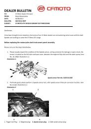
IMPORTANT NOTICE<br />
OPERATOR AND PASSENGER<br />
This motorcycle is designed to carry the operator and one passenger.<br />
ON-ROAD USE<br />
This motorcycle is designed to be used only on the road.<br />
READ THIS OWNER'S MANUAL CAREFULLY<br />
Pay special attention to statements preceded by the following words:<br />
WARNING<br />
Indicates a strong possibility of severe personal injury or death if instructions are not followed.<br />
CAUTION<br />
Indicates a possibility of personal injury or equipment damage if instructions are not followed.<br />
NOTE<br />
Gives helpful information.<br />
This manual should be considered a permanent part of the motorcycle and should remain with the motorcycle when resold or otherwise<br />
transferred to a new owner or operator.
CONTENTS<br />
SPECIFICATION<br />
OPERATION INSTRUCTION<br />
3<br />
4<br />
EQUIPMENT USAGE<br />
STEERING LOCK<br />
17<br />
17<br />
SAFETY PRECAUTIONS<br />
4<br />
SEAT<br />
17<br />
PRIOR TO STARTING VEHICLE<br />
5<br />
HELMET HOLDER<br />
18<br />
CORRECT ATTIRE<br />
OPERATION<br />
5<br />
6<br />
STORAGE COMPARTMENT<br />
SELF INSPECTIONS BEFORE OPERATION<br />
18<br />
19<br />
CARGO<br />
7<br />
BRAKES<br />
19<br />
MODIFICATION<br />
8<br />
TIRES<br />
21<br />
ATTACHMENT<br />
8<br />
CLUTCH<br />
23<br />
MUFFLER<br />
8<br />
FUEL<br />
24<br />
PARTS LOCATION<br />
9<br />
ENGINE OIL<br />
25<br />
METER READING AND USAGE<br />
12<br />
LIGHTS AND WINKER<br />
25<br />
METER<br />
12<br />
BACK MIRROR<br />
26<br />
TACHOMETER<br />
FUEL GAUGE<br />
12<br />
13<br />
LICENSE PLATE<br />
OPERATION<br />
26<br />
26<br />
INDICATOR LAMPS<br />
13<br />
PRE-RIDE INSPECTION<br />
26<br />
SWITCH OPERATION<br />
14<br />
STARTING THE ENGINE<br />
27<br />
MAIN SWITCH<br />
14<br />
IF ENGINE CANNOT BE STARTED<br />
28<br />
STARTER BUTTON<br />
14<br />
RUNNING-IN<br />
28<br />
HEADLIGHT<br />
15<br />
RIDING<br />
29<br />
KEYS<br />
15<br />
BRAKING<br />
30<br />
WINKER SWITCH<br />
16<br />
PARKING<br />
30<br />
HORN BUTTON<br />
16<br />
1
MAINTENANCE<br />
31<br />
SAFE DRIVING<br />
51<br />
MAINTENANCE SCHEDULE<br />
32<br />
PREPARATION BEFORE DRIVING<br />
51<br />
TOOL KIT<br />
34<br />
DRIVING METHOD<br />
52<br />
FRAME AND ENGINE NUMBERS<br />
34<br />
DRIVING POSITION<br />
52<br />
MAINTENANCE PRECAUTIONS<br />
35<br />
PRECAUTION WHEN DRIVING<br />
53<br />
THROTTLE OPERATION<br />
35<br />
STARTING<br />
54<br />
AIR CLEANER<br />
36<br />
TURNING METHOD<br />
55<br />
ENGINE OIL<br />
37<br />
PRINCIPLE OF TURN<br />
55<br />
SPARK PLUG<br />
38<br />
EFFECT OF SPEED<br />
55<br />
DRIVE CHAIN<br />
39<br />
3 POSITIONS OF TURNING<br />
56<br />
WHEEL REMOVAL<br />
41<br />
TURNING METHOD<br />
57<br />
BRAKE PAD WEAR<br />
43<br />
PRECAUTION WHEN TURNING<br />
58<br />
IDLE SPEED<br />
44<br />
BRAKING METHOD<br />
59<br />
SIDE STAND<br />
44<br />
BASIC PRINCIPLE OF BRAKE(FRICTION FORCE)<br />
59<br />
BATTERY<br />
45<br />
RESTRAINT OF BRAKING EFFECT (INERTIA)<br />
59<br />
FUSE REPLACEMENT<br />
46<br />
BRAKING METHOD<br />
60<br />
BULB REPLACEMENT<br />
47<br />
COMPARISION OF BRAKING DISTANCE<br />
60<br />
CABLE RUBBER PART<br />
49<br />
IMPACT WHEN COLLISION<br />
60<br />
CLEANING<br />
49<br />
WIRING DIAGRAM<br />
61<br />
STORAGE GUIDE<br />
50<br />
2
SPECIFICATION<br />
ITEM DATA ITEM DATA<br />
LENGTH×WIDTH×HEIGHT<br />
2,010×740×1,040mm<br />
FUEL TANK CAPACITY<br />
16.0l<br />
WHEEL BASE<br />
1,380mm<br />
ENGINE OIL CAPACITY<br />
1.1l<br />
GROUND CLEARANCE<br />
SEAT HEIGHT<br />
150mm<br />
780mm<br />
TIRE SIZE<br />
FR.<br />
RR.<br />
110/70-17 54P<br />
140/70-17 69P<br />
DRY WEIGHT<br />
PASSENGER<br />
130kgf<br />
OPERATOR AND ONE PASSENGER<br />
SUSPENSION<br />
FR.<br />
RR.<br />
TELESCOPIC<br />
SINGLE ARM<br />
ENGINE TYPE<br />
AIR & OIL COOLED<br />
4 CYCLE, SOHC<br />
BRAKE<br />
FR.<br />
RR.<br />
HYDRAULIC DISK<br />
HYDRAULIC DISK<br />
PISTON DISPLACEMENT<br />
124.1cc<br />
SPARK PLUG<br />
CR8EH-9<br />
BORE AND STROKE<br />
56.5×49.5mm<br />
FUSE<br />
15A<br />
STARTING SYSTEM<br />
START MOTOR<br />
HEADLIGHT BULB<br />
12V 35W/35W<br />
TRANSMISSION TYPE<br />
5 STEPS RETURN<br />
STOP/TAIL LIGHT BULB<br />
12V 21/5W<br />
IGNITION SYSTEM<br />
DC-C.D.I<br />
WINKER BULB<br />
12V 10W×4<br />
BATTERY CAPACITY<br />
12V 10Ah(MF TYPE)<br />
POSITION LIGHT BULB<br />
12V 5W<br />
3
OPERATION INSTRUCTION<br />
This manual describes matters pertaining to correct operation,<br />
safe operation and simple maintenance of the vehicle you<br />
purchased.<br />
To ensure more comfortable and safer operation, make sure to<br />
read this manual carefully prior to operation.<br />
●The photographs and drawings shown in this manual may<br />
differ from those of actual vehicles due to changes in vehicle<br />
specifications and modifications made.<br />
●This motorcycle is designed for 2 riders including the<br />
operator.<br />
CAUTION<br />
●Do not use polluted gasoline.<br />
Using polluted gasoline will cause rust inside the<br />
fuel tank, and will close the supply of fuel to the<br />
carburetor, leading to an improper engine starting<br />
or may cause serious damage to an engine.<br />
●Do not use polluted or low-grade oil.<br />
Always use genuine oil to protect and extend<br />
motorcycle performance and its life span.<br />
●If any failure occurs due to the use of polluted<br />
gasoline or oil, such failure will be excluded from<br />
being eligible for repairs under the warranty.<br />
SAFETY PRECAUTIONS<br />
●Careful driving and the wearing of proper attire and safety<br />
equipment are the most important factors in the safe operation<br />
of the vehicle. Please obey traffic regulations and do not be<br />
hurried and careless.<br />
●Many new vehicle owners operate their newly purchased<br />
vehicles with great care and attention to safety factors.<br />
However, after becoming accustomed to the operations are<br />
often discarded, which can lead to accidents. Please don't let<br />
this happen to you and always approach the operation of your<br />
vehicle with the safety considerations needed.<br />
When operating the motorcycle, always keep in mind and<br />
obey the notes of precaution printed on the “ Safety<br />
Precaution Label”attached to the motorcyle.<br />
●Always wear helmet.<br />
●Always put on gloves.<br />
●Observe posted speed limits.<br />
●Park the motorcycle away from people (especially<br />
children) as the muffler can get very hot.<br />
●For safety, do not illegally modify the vehicle.<br />
●Regularly conduct specified maintenance<br />
inspections.<br />
<br />
Brakes, Tires, Oil, Lights, Horn, Instruments<br />
4
PRIOR TO STARTING VEHICLE<br />
●Read user's manual carefully.<br />
●Conduct maintenance checks prior to operation.<br />
●Always maintain motorcycle in clean status and carry out<br />
specified maintenance checks.<br />
●Make sure to stop engine and stay away from fire when<br />
fueling.<br />
●Exhaust gas contains harmful substance such as carbon<br />
monoxide. Start engine in well-ventilated places.<br />
CORRECT ATTIRE<br />
●Always make sure to wear helmet for safety. Wear gloves and<br />
safety goggles.<br />
●Do not wear uniforms which might hinder operation. It is<br />
dangerous if the uniform is caught by brake lever or by the<br />
rotating part of drive chain.<br />
●Do not wear slippers which might obstruct brake operation or<br />
transmission gear operation.<br />
●Many automobile/motorcycle accidents happen because the<br />
automobile driver does not “see” the motorcyclist.<br />
Make yourself conspicuous to help avoid the accident that<br />
wasn’t your fault :<br />
- Wear bright or reflective clothing.<br />
- Don’t ride in another motorist’s “blind spot”.<br />
WARNING<br />
●Not wearing a helmet increases the chance of serious<br />
injury or death in a crash.<br />
●Be sure you and your passenger always wear a helmet,<br />
eye protection and other protective apparel when you<br />
ride.<br />
5
Correct shirts or jackets with<br />
tight-fitting sleeves should be<br />
worn,<br />
A helmet should always be<br />
worn and the helmet chin<br />
strap should be securely<br />
fastened.<br />
Alwaysputongloves.<br />
Shoes should fit properly, and shoes having little or<br />
noheelshouldbeworn.<br />
OPERATION<br />
●Operators should naturally fix bodies to keep smooth driving.<br />
●Please check whether or not you are unnaturally strained and<br />
strung up.<br />
●Driving pose has a great influence on safe operation.<br />
Please always maintain the center of your body in the middle of<br />
seat. Especially do not sit at the rear seat because it may lessen<br />
the weight of front wheel and cause trembling steering wheel.<br />
●A passenger should hold on to the vehicle or the operator with<br />
both hands and keep both feet on the pillion step bar.<br />
●When wanting to turn, slightly lean to body toward the<br />
direction of the turn. It is unsafe if the body is not moved in<br />
union with the vehicle.<br />
●Curvy roads and poor, unpaved roads constantly change in<br />
surface quality. Driving on these roads can be unsafe if certain<br />
safety precautions are not followed.<br />
●In order to safely drive through these driving conditions,<br />
anticipate coming road conditions, slow down to at least half<br />
the normal speed, and relax your shoulders and wrists while<br />
securely holding the handles.<br />
●Driving with one or both hands not holding the handles or the<br />
front wheel lifted can cause severe injury or death of the driver<br />
resulted from the turnover of the vehicle.<br />
6
CARGO<br />
●When carrying cargo, you must keep in mind that operating the<br />
motorcycle, especially when turning, will be different.<br />
●Make sure not to overload the motorcycle with goods as this<br />
can make the motorcycle unstable during operation.<br />
WARNING<br />
●Overloading or improper loading can cause a crash and<br />
you can be seriously hurt or killed.<br />
●Follow all load limits in this manual.<br />
CAUTION<br />
MAXIMUMLOAD:30kg<br />
●Only load cargo in or on designated areas as<br />
placing or fastening cargo to other areas can cause<br />
damage to the vehicle.<br />
●Do not place articles between the frame body<br />
cover and engine as this can burn the goods.<br />
●Do not attach large or heavy items (such as a<br />
sleeping bag or tent) to the handle bars or fork.<br />
Unstable handling or slow steering response may<br />
result.<br />
7
MODIFICATION<br />
●Modification of vehicle structure of function deteriorates<br />
manipulatability or causes exhaust noise to become louder<br />
shortening the vehicle life. These modifications are not only<br />
prohibited by law but also are the acts harmful to other people.<br />
Modifications are not covered by warranty.<br />
MUFFLER<br />
●Pay particular attention to fellow passenger so that he/she can<br />
prevent getting burnt by the hot muffler during travel.<br />
ATTACHMENT<br />
●Except designated attachment by DAELIM MOTOR CO.,<br />
LTD., don't attach any extra lighting device, because it may<br />
cause an early discharging of battery.<br />
●Carefully inspect the accessory to make sure it does not<br />
obscure any lights, reduce ground clearance and banking angle,<br />
or limit suspension travel, steering travel or control operation.<br />
●Do not add electrical equipment that will exceed the<br />
motorcycle’s electrical system capacity. A blown fuse could<br />
cause a dangerous loss of lights or engine power.<br />
●This vehicle was not designed to pull a sidecar or trailer.<br />
Handling may be seriously impaired of so equipped.<br />
CAUTION<br />
●Do not park in the place where many pedestrians<br />
are passing through. Pedestrians or children can be<br />
burned by contacting with the muffler.<br />
●Fellow passenger care must pay enough attention<br />
not to be burn by contacting with the muffler.<br />
●If haystack or vinyl is stuck to the muffler, fire can<br />
be occurred.<br />
8
20<br />
40<br />
0<br />
60<br />
80<br />
100<br />
120<br />
140<br />
160<br />
mph<br />
km/h<br />
2<br />
0<br />
F<br />
3<br />
4<br />
x1000rpm<br />
E<br />
5 6<br />
7<br />
8<br />
9<br />
10<br />
11<br />
PARTS LOCATION<br />
SPEEDOMETER<br />
TACHOMETER<br />
BACK MIRROR<br />
FUEL GAUGE<br />
FRONT BRAKE FLUID<br />
RESERVOIR<br />
BACK MIRROR<br />
CHOKE LEVER<br />
N<br />
FRONT BRAKE LEVER<br />
PASSING SWITCH<br />
THROTTLE GRIP<br />
CLUTCH LEVER<br />
HEADLIGHT SWITCH<br />
HEADLIGHT<br />
DIMMER SWITCH<br />
STARTER BUTTON<br />
WINKER SWITCH<br />
HORN BUTTON<br />
FUEL FILLER CAP<br />
MAIN SWITCH<br />
9
PARTS LOCATION<br />
REAR BRAKE FLUID RESERVOIR<br />
BATTERY<br />
HEADLIGHT<br />
REAR TIRE<br />
FRONT TIRE<br />
CALIPER<br />
BRAKE DISK<br />
MUFFLER<br />
PILLION STEP BAR<br />
MAIN STEP BAR<br />
REAR BRAKE PEDAL<br />
OIL FILLER CAP/DIPSTICK<br />
10
PARTS LOCATION<br />
TOOL BOX<br />
HELMET HOLDER<br />
REAR CUSHION<br />
RADIATOR<br />
CALIPER<br />
PILLION STEP BAR<br />
BRAKE DISK<br />
GEAR SHIFT PEDAL<br />
MAIN STAND SIDE STAND MAIN STEP BAR<br />
11
METER READING AND USAGE<br />
SPEEDOMETER<br />
TACHOMETER<br />
ODOMETER<br />
x1000rpm<br />
F<br />
E<br />
N<br />
TRIPMETER INDICATORLAMPS FUELGAUGE<br />
METER<br />
SPEEDOMETER<br />
ODOMETER<br />
<br />
Shows riding speed.<br />
<br />
Shows accumulated mileage.<br />
<br />
Shows mileage per trip.<br />
To reset the tripmeter, turn the tripmeter<br />
knob to the direction of arrow.<br />
TACHOMETER<br />
Shows engine revolutions per minute.<br />
<br />
Never allow the tachometer needle to<br />
enter the red zone, even after the engine<br />
has been broken in.<br />
CAUTION<br />
●Running the engine beyond<br />
recommended maximum engine<br />
speed (the beginning of the<br />
tachometer red zone) can damage the<br />
engine.<br />
TACHOMETER<br />
x1000rpm<br />
N<br />
TRIPMETERRESETKNOB<br />
F<br />
E<br />
TRIPMETER<br />
TACHOMETERREDZONE<br />
12
FUEL GAUGE<br />
Indicates amount of gasoline in fuel tank.<br />
(The fuel gauge needle always indicates<br />
gasoline level regardless of whether main<br />
switch is in "OFF" position or in "ON"<br />
position.) If needle is within E mark,<br />
immediately fill gasoline. Balance at this<br />
time is approximately 1.2 litres.<br />
TACHOMETER<br />
x1000rpm<br />
INDICATOR LAMPS<br />
<br />
Lights when the headlight is on high<br />
beam. (blue)<br />
<br />
Lights when the transmission is in neutral.<br />
(green)<br />
<br />
Flashes when the left turn signal operates.<br />
(green)<br />
<br />
Flashes when the right turn signal<br />
operates. (green)<br />
NEUTRALINDICATOR<br />
N<br />
HIGHBEAMINDICATOR<br />
x1000rpm<br />
F<br />
E<br />
F<br />
E<br />
LEFTWINKER<br />
INDICATOR<br />
RIGHTWINKER<br />
INDICATOR<br />
FUELGAUGE<br />
WARNING<br />
●To avoid running out of fuel that<br />
may result in a sudden stop.<br />
13
PUSH<br />
SWITCH OPERATION<br />
MAIN SWITCH<br />
KEY<br />
OFF<br />
LOCK<br />
OFF<br />
LOCK<br />
ON<br />
IGNITION<br />
ON<br />
MAIN<br />
SWITCH<br />
The main switch is used to turn on or turn<br />
off engine.<br />
The main switch is below the indicator<br />
panel.<br />
Key<br />
Function<br />
position<br />
Starts engine. Power<br />
ON is supplied to<br />
electrical circuits.<br />
OFF<br />
LOCK<br />
Stops engine. Cuts<br />
off all electrical<br />
circuits.<br />
Locks steering<br />
wheel. Cuts off all<br />
electrical circuits<br />
and steering wheel<br />
is locked.<br />
Key<br />
Removal<br />
Key<br />
cannot be<br />
removed<br />
Key<br />
can be<br />
removed<br />
Key<br />
can be<br />
removed<br />
WARNING<br />
●Do not manipulate main switch key<br />
during operation. If the main switch<br />
key is placed on "Off" or "Lock"<br />
position, all electrical system will not<br />
function. Never operate the main<br />
switch key during travel as it might<br />
cause unexpected accidents, If it is<br />
necessary to remove the main switch<br />
key, stop the vehicle first prior to<br />
removing.<br />
CAUTION<br />
●Prior to dismounting from the<br />
motorcycle, make sure to lock the<br />
steering wheel and remove key.<br />
●If the key is left in "ON" position<br />
without starting engine, battery is<br />
discharged.<br />
●Do not use a number of keys together<br />
with a metal key holder. The keys<br />
and the key holder may cause<br />
scratches or other damage to the<br />
cover while operating the motorcycle.<br />
(Recommend cloth or leather key<br />
holders)<br />
14
KEYS<br />
This motorcycle has two keys and a key<br />
number plate.<br />
You will need the key number if you ever<br />
have to replace a lost key. Store the plate<br />
in a safe place.<br />
HEADLIGHT<br />
<br />
The headlight switch has three positions;<br />
, and OFF marked by a dot to the<br />
below of .<br />
:Headlight, taillight, position<br />
light and meter lights on.<br />
: Position light, taillight and<br />
meter lights on.<br />
OFF (dot) : Headlight, taillight, position<br />
light and meter lights off.<br />
<br />
Push the dimmer switch to D (HI) to<br />
select high beam or to D (LO) to select<br />
low beam.<br />
<br />
When this switch is pressed, the headlight<br />
flashes on to signal approaching cars or<br />
when passing.<br />
PASSINGLIGHTCONTROL<br />
SWITCH<br />
KEYNUMBERPLATE<br />
HEADLIGHTSWITCH<br />
NOTE<br />
●Do not drop the keys or set heavy<br />
objects on them.<br />
●Do not grind, drill or in any way alter<br />
the original shape of the keys.<br />
●Keep the keys away from magnetic<br />
objects.<br />
HEADLIGHTDIMMERSWITCH<br />
CAUTION<br />
●Use the high beam only in the<br />
suburban road or when the usage of<br />
the high beam not hinder the safe<br />
driving of the car ahead.<br />
15
STARTER BUTTON WINKER SWITCH HORN BUTTON<br />
The starter button is next to the throttle<br />
grip.<br />
When the starter button is pressed, the<br />
starter motor cranks the engine. See page<br />
24 for the starting procedure.<br />
Move to (L) to signal a left turn, (R)<br />
to signal a righ turn. Press to turn signal<br />
off.<br />
Press the button to sound the horn.<br />
WINKERSWITCH<br />
STARTERBUTTON<br />
CAUTION<br />
●Do not press starter button repeatedly<br />
because it consumes great amount of<br />
power causing battery to be<br />
exhausted sooner.<br />
CAUTION<br />
●The winker switch does not automatically<br />
turn back to its original<br />
position after completing the turn.<br />
Please set the switch back to its<br />
center position after turning.<br />
HORNBUTTON<br />
16
EQUIPMENT USAGE<br />
STEERING LOCK<br />
To lock the steering, turn the handlebars<br />
all the way to the left or right, turn the key<br />
to LOCK while pushing in.<br />
Remove the key.<br />
To unlock the steering, turn the key to<br />
OFF while pushing in.<br />
Pushin<br />
KEY<br />
SEAT<br />
<br />
To remove the front seat, insert the<br />
ignition key into the seat lock.<br />
Turn the ignition key counterclockwise,<br />
and then pull the seat back and up.<br />
To install the front seat, insert the tab into<br />
the recess under the frame and push down<br />
on the rear of the seat.<br />
<br />
To remove the rear seat, remove both<br />
front seat and center cover, remove the<br />
seat mounting bolt, and then pull the seat<br />
front and up.<br />
To install the seat, insert the tab into the<br />
recess under the frame and tighten the<br />
mount bolt scurely.<br />
TAB<br />
FRONTSEAT<br />
FRONTSEAT<br />
CENTERCOVER<br />
REARSEAT<br />
TurntoLOCK<br />
WARNING<br />
●Do not turn the key to LOCK while<br />
riding the vehicle; loss of vehicle<br />
control will result.<br />
KEY<br />
MOUNTINGBOLT<br />
17
HELMET HOLDER<br />
The helmet holder is on the left side below<br />
the seat. Insert the ignition key and turn it<br />
clockwise to unlock.<br />
Hang your helmet on the holder pin. Turn<br />
the key counterclockwise to lock the<br />
holder and then remove the key.<br />
HELMETHOLDER<br />
STORAGE COMPARTMENT<br />
The storage compatment is under the seat.<br />
This owner’s manual and the tool kit<br />
should be stored in the compartment.<br />
Remove the front seat (page 17).<br />
Pull out the center cover while turning the<br />
lever to the left.<br />
Reinstall the center cover by aligning its<br />
tabs and turning the lever to the right.<br />
CENTERCOVER<br />
NOTE<br />
●When washing your motorcycle, be<br />
careful not to flood this area with<br />
water.<br />
●This compartment is for light weignt<br />
items.<br />
KEY<br />
HOLDERPIN<br />
TOOLKIT<br />
WARNING<br />
●The helmet holder is designed for<br />
helmet security while parked. Do not<br />
ride with a helmet attached to the<br />
holder; the helmet may interfere with<br />
safe operation and result in loss of<br />
control.<br />
18
SELF INSPECTIONS BEFORE OPERATION<br />
Self inspect the motorcycle and have<br />
regular maintenance inspections for<br />
increased safety and the prevention of<br />
accidents.<br />
Self inspections before operation should<br />
be performed on a daily basis prior to<br />
operating the motorcycle.<br />
BRAKES<br />
Both the front and rear brake are the<br />
hydraulic disk type.<br />
As the brake pad wear, the brake fluid<br />
level drops.<br />
There are no adjustments to perform, but<br />
fluid level and pad wear must be inspected<br />
periodically. The system must be<br />
inspected frequently to ensure there are no<br />
fluid leaks.<br />
If the control lever or pedal free travel<br />
becomes excessive and the brake pads are<br />
not worn beyond the recommended limit,<br />
there is probably air in the brake system<br />
and it must be bled. See your authorized<br />
<strong>Daelim</strong> dealer for this service.<br />
[FRONT BRAKE]<br />
<br />
Lightly squeeze the brake lever until<br />
tension is felt to check for an appropriate<br />
amount of free play. No free play in the<br />
brake lever or overly loose brake lever is<br />
indication of a problem in the brake<br />
system.<br />
BRAKE LEVER FREE PLAY : 10~20mm<br />
10~20mm<br />
<br />
WARNING<br />
●Brake fluid may cause irritation.<br />
Avoid contact with skin or eyes. In<br />
case of contact, flush thoroughly with<br />
water and call a doctor if your eyes<br />
were exposed.<br />
●KEEP OUT OF REACH OF CHIL-<br />
DREN<br />
CAUTION<br />
●When adding brake fluid, be very<br />
careful not to allow foreign materials<br />
to enter the reserve tank.<br />
●Do not fill past upper level.<br />
This can cause brake fluid to leak out<br />
of the reserve tank.<br />
●Do not let brake fluid contact vehicle<br />
parts as this damages painted areas.<br />
If oil contacts parts, quickly clean the<br />
fluid off using a dry cloth.<br />
●Use recommended brake fluid as<br />
other types can undergo chemical<br />
changes.<br />
19
Check that the fluid level is above the<br />
LOWER level mark with the motercycle<br />
in an upright position.<br />
Brake fluid must be added to the reservoir<br />
whenever the fluid level begins to reach<br />
the LOWER level mark.<br />
1. Remove the screws and master cylinder<br />
cap, diaphragm plate, and diaphragm.<br />
2. Fill the reservoir with recommended<br />
brake fluid from a sealed container up<br />
to the UPPER level mark.<br />
RECOMMENDED BRAKE FLUID<br />
is DOT3<br />
3. Reinstall the diaphragm, diaphragm<br />
plate, and master cylinder cap.<br />
4. Tighten the screws securely.<br />
Other checks :<br />
●Make sure there are no fluid leaks.<br />
●Check for deterioration or cracks in the<br />
hose and fitting.<br />
●Check the brake pad for wear when<br />
refilling with brake fluid.<br />
UPPER<br />
LEVEL<br />
LOWER<br />
LEVEL<br />
SCREWS<br />
MASTER<br />
CYLINDER<br />
CAP<br />
DIAPHRAGM<br />
PLATE<br />
DIAPHRAGM<br />
[REAR BRAKE]<br />
<br />
WARNING<br />
●Brake fluid may cause irritation.<br />
Avoid contact with skin or eyes. In<br />
case of contact, flush thoroughly with<br />
water and call a doctor if your eyes<br />
were exposed.<br />
●KEEP OUT OF REACH OF CHIL-<br />
DREN<br />
CAUTION<br />
●When adding brake fluid, be very<br />
careful not to allow foreign materials<br />
to enter the reserve tank.<br />
●Do not fill past upper level.<br />
This can cause brake fluid to leak out<br />
of the reserve tank.<br />
●Do not let brake fluid contact vehicle<br />
parts as this damages painted areas.<br />
If oil contacts parts, quickly clean the<br />
fluid off using a dry cloth.<br />
●Use recommended brake fluid as<br />
other types can undergo chemical<br />
changes.<br />
20
TIRES<br />
Check the brake fluid level with the<br />
motorcycle in an upright position.<br />
Brake fluid must be added to the reservoir<br />
whenever the fluid level begins to reach<br />
the LOWER level mark.<br />
1. Remove the reservoir cap, reservoir cap<br />
plate, and diaphragm.<br />
2. Fill the reservoir with recommended<br />
brake fluid from a sealed container up<br />
to the UPPER level mark.<br />
UPPER<br />
LOWER<br />
UPPERLEVELMARK<br />
<br />
Check for an appropriate level of air<br />
pressure by examining how the tire sits on<br />
the ground. If you notice any abnormalities<br />
in the shape of the tire with regard to<br />
the area contacting the ground, use a tire<br />
gauge to check tire pressure and adjust the<br />
tire pressure to the appropriate level.<br />
<br />
RECOMMENDED BRAKE FLUID is<br />
DOT3<br />
LOWERLEVELMARK<br />
SIZE<br />
FRONT<br />
REAR<br />
110/70-17 54P<br />
140/70-17 69P<br />
3. Reinstall the diaphragm, reservoir cap<br />
plate and cap securely.<br />
Other checks :<br />
●Make sure there are no fluid leaks.<br />
●Check for deterioration or cracks in the<br />
hose and fitting.<br />
●Check the brake pad for wear when<br />
refilling with brake fluid.<br />
RESERVOIRCAP<br />
RESERVOIRCAP<br />
PLATE<br />
DIAPHRAGM<br />
TIRE<br />
PRESSURE<br />
(kgf/§†)<br />
WITH ONE<br />
PERSON<br />
WITH TWO<br />
PERSON<br />
FRONT 2.00<br />
REAR 2.00<br />
FRONT 2.00<br />
REAR 2.00<br />
UPPER<br />
LOWER<br />
21
Check tire tread and sides for cracks and<br />
damage.<br />
<br />
Check tire tread for signs of abnormal<br />
wear.<br />
ABNORMAL<br />
WEAR<br />
CRACKS<br />
DAMAGE<br />
<br />
Check tire tread and sides for nails, rocks,<br />
etc. That might have become wedged in<br />
the tire.<br />
<br />
●Check the wear indicator (wear limit<br />
marking) to see if there is an<br />
insufficient amount of tread remaining.<br />
●If the indicators are visible, replace tire<br />
with a new one.<br />
WEARINDICATOR<br />
(WEARLIMITMARKING)<br />
NAIL<br />
ROCK<br />
WEARINDICATOR<br />
LOCATIONMARKING<br />
CAUTION<br />
●If air pressure is inadequate or if<br />
there are cracks, damage or abnormal<br />
wear on tires, it may cause trembling<br />
steering wheel and flat tire.<br />
●Insufficient air pressure may cause<br />
the heavy steering wheel marking<br />
handling difficult, fuel over consumption<br />
and the excessive wear of<br />
tire outer area and excessive air<br />
pressure may cause easier wheel<br />
handling and lower fuel consumption.<br />
But it may also cause the<br />
excessive wear of tire center area.<br />
●This motorcycle is equipped with<br />
tubeless tires. If you have flat tires,<br />
please contact authorised maintenance<br />
shops for inspection.<br />
22
CLUTCH<br />
Clutch adjustment may be reguired if the<br />
motorcycle stalls when shifting into gear<br />
or tends to creep; or if the clutch slips,<br />
causing acceleration to lag behind engine<br />
speed.<br />
Minor adjustments can be made with the<br />
clutch cable adjuster at the lever.<br />
CLUTCH LEVER FREE PLAY:10~20mm<br />
<br />
1. Loosen the lock nut and turn the<br />
adjuster. Tighten the lock nut and check<br />
the adjustment.<br />
2. If the adjuster is threaded out near its<br />
limit or if the correct free play cannot<br />
be obtained, loosen the lock nut and<br />
turn in the cable adjuster completely.<br />
Tighten the lock nut.<br />
4. Start the engine, pull in the clutch lever<br />
and shift into gear. Make sure the<br />
engine does not stall and the motorcycle<br />
does not creep. Gradually release the<br />
clutch lever and open the throttle.<br />
The motorcycle should begin to move<br />
smoothly and accelerate gradually.<br />
LOCKNUT<br />
ADJUSTER<br />
LOCKNUT<br />
Decrease<br />
freeplay<br />
Increase<br />
freeplay<br />
Decrease<br />
freeplay<br />
Increase<br />
freeplay<br />
CLUTCHCABLE<br />
ADJUSTER<br />
3. Loosen the lock nut at the lower end of<br />
the cable. Turn the adjusting nut to<br />
obtain the specified free play. Tighten<br />
the lock nut and check the adjustment.<br />
NOTE<br />
●If proper adjustment cannot be<br />
obtained or the clutch does not work<br />
correctly, see your <strong>Daelim</strong> dealer.<br />
23
24<br />
FUEL<br />
<br />
●ON: With the fuel cock in the ON<br />
position, fuel with flow from the main<br />
fuel supply to the carburetor.<br />
●OFF: With the fuel cock in the OFF<br />
position, fuel cannot flow from the tank<br />
to the carburetor.<br />
Turn the fuel cock OFF whenever the<br />
motorcycle is not in use.<br />
●RES: With the fuel cock in the RES<br />
position, fuel with flow from the<br />
reserve fuel supply to the carburetor.<br />
Use the reserve fuel only when the<br />
main supply in gone. Refill the tank as<br />
soon as posible after switching to RES.<br />
The reserve fuel supply is : 1.1<br />
WARNING<br />
●To avoid running out of fuel that may<br />
result in a sudden stop, learn how to<br />
operate the fuel cock when riding the<br />
motorcycle.<br />
NOTE<br />
●Remember to check that the fuel<br />
cock is in the ON position each time<br />
you refuel. If the cock is left in the<br />
RES position, you may run out of<br />
fuel with no reserve.<br />
OFF<br />
ON<br />
RES<br />
ON<br />
OFF<br />
OFF<br />
RES<br />
ON<br />
<br />
The fuel tank capacity including the<br />
reserve supply is : 16.0<br />
To open the fuel fill cap;<br />
1. Insert the ignition key and turn it<br />
clockwise.<br />
2. The cap is hinged and will lift up.<br />
3. Do not overfill the tank. There should<br />
be no fuel in the filler neck.<br />
4. After refueling, to close the fuel fill<br />
cap, push the cap into the filler neck<br />
until it snaps closed and locks.<br />
5. Remove the key.<br />
OFF<br />
RES<br />
RES<br />
ON<br />
KEY<br />
WARNING<br />
FILLERNECK<br />
FUELFILLERCAP<br />
●Gasoline is extremely flammable and<br />
is explosive under certain conditions.<br />
Refuel in a well-ventilated area with<br />
the engine stopped. Do not smoke or<br />
allow flames or sparks in the area<br />
where gasoline is stored or where the<br />
fuel tank is refueled.<br />
●Do not overfill the tank. After<br />
refueling, make sure the fuel fill cap<br />
is closed securely.<br />
●Avoid repeated or prolonged contact<br />
with skin or breathing of vapor.<br />
KEEP OUT OF REACH OF CHILDREN.
ENGINE OIL<br />
<br />
Check the engine oil level each day before<br />
riding the motorcycle.<br />
The level must be maintained between the<br />
upper and lower level marks on the oil<br />
level gauge.<br />
1. Start the engine and let it idle for a few<br />
minutes.<br />
2. Stop the engine and put the motorcycle<br />
on its main stand on level ground.<br />
3. After a few minutes, remove the oil<br />
level gauge, wipe it clean, and reinsert<br />
the gauge without screwing it in.<br />
Remove the gauge. The oil level should<br />
be between the upper and lower marks<br />
on the oil level gauge.<br />
4. If required, add the specified oil up to<br />
the upper level mark.<br />
Do not overfill.<br />
5. Reinstall the oil level gauge.<br />
Check for oil leaks.<br />
UPPER<br />
LEVEL<br />
LOWER<br />
LEVEL<br />
CAUTION<br />
●Running the engine with insufficient<br />
oil pressure may cause serious engine<br />
damage.<br />
OILLEVELGAUGE<br />
LIGHTS AND WINKER<br />
<br />
Start the engine and make sure the lights<br />
turn on. Also check to see if the lights are<br />
damaged or if there is dirt on them.<br />
<br />
Turn the main switch to ON.<br />
While separately operating the front and<br />
rear brakes, check to see if the brake light<br />
turns on. Also check to see if there is any<br />
damage to the lens or if there is dirt on the<br />
brake light.<br />
<br />
Turn the main switch to ON.<br />
Check to see if all the winker in the front<br />
and rear of the vehicle (including left and<br />
right sides) are flashing properly. At the<br />
same time, check to make sure that the<br />
automatic sound signal of the winker is<br />
working. Check also to see if any of the<br />
lens are damaged or dirty.<br />
25
BACK MIRROR<br />
Sit squarely on the seat and check to see if<br />
you have a good view behind the vehicle<br />
by looking at the back mirrors. Also check<br />
for dirt and damage on the back mirrors.<br />
LICENSE PLATE<br />
Check to see if there is any dirt or damage<br />
to the license plate.<br />
Also check to see if the license plate is<br />
firmly secured to the vehicle.<br />
OPERATION<br />
PRE-RIDE INSPECTION<br />
WARNING<br />
●If the pre-ride inspection is not<br />
performed, severe personal injury or<br />
motorcycle damage may result.<br />
Inspect your motorcycle every day before<br />
you ride it. The items listed here will only<br />
take a few minutes to inspect, and in the<br />
long run they can save time, expense, and<br />
possibly your life.<br />
●Check for signs of abnormality which<br />
might have occurred on the previous<br />
day.<br />
●Engine oil level - add engine oil if<br />
required (page 25). Check for leaks.<br />
●Fuel level - fill fuel tank when necessary<br />
(page 24). Check for leaks.<br />
●Front and rear brakes - check operation;<br />
make sure that is no brake fluid leakage<br />
(page 19~21).<br />
●Tires - check condition and pressure<br />
(page 21~22).<br />
●Drive chain - check condition and slack<br />
(page 39~40). Adjust and lubricate if<br />
necessary.<br />
●Throttle - check for smooth opening<br />
and full closing in all steering positions.<br />
●Lights and horn - check that headlight,<br />
tail/brake light, turn signals, indicators<br />
and horn function properly.<br />
●Side stand switch ignition cut-off<br />
system - check for proper function<br />
(page 44).<br />
●Angle rear view mirror.<br />
CAUTION<br />
●Observe safety rules when conducting<br />
inspections.<br />
●Conduct inspections on a flat, solid<br />
ground with the main stand erected.<br />
If you are unable to correct trouble even<br />
after you make adjustment or correction,<br />
contact authorized maintenance shops,<br />
dealers or designated repair shops for<br />
necessary inspection and repairs.<br />
26
STARTING THE ENGINE<br />
Always follow the proper starting<br />
procedure described below.<br />
●This motorcycle is equipped with a side<br />
stand ignition cut-off system. The<br />
engine cannot be started if the side<br />
stand is down, unless the transmission<br />
is in neutral. If the side stand is up, the<br />
engine can be started in neutral or in<br />
gear with the clutch lever pulled in.<br />
After starting with the side stand down,<br />
the engine will shut off if the<br />
transmission is put in gear before<br />
raising the side stand.<br />
WARNING<br />
●Never run the engine in an enclosed<br />
area. The exhaust contains poisonous<br />
carbon monoxide gas that can cause<br />
loss of consciousness and lead to<br />
death.<br />
CAUTION<br />
●Do not keep the starter button<br />
pressed for more than 5 seconds at a<br />
time. Release the starter button for<br />
approximately 10 seconds before<br />
pressing it again.<br />
<br />
Before starting, insert the key, turn the<br />
ignition switch ON and confirm the<br />
following:<br />
●The transmission is in NEUTRAL<br />
(neutral indicator light ON)<br />
●The fuel cock is ON.<br />
<br />
1. Pull the chock lever back all the way to<br />
Fully ON.<br />
FullyON<br />
CHOKELEVER<br />
FullyOFF<br />
2. Close throttle grip, and press starter<br />
button.<br />
3. Once engine is started, pull and release<br />
throttle grip repeatedly to run engine<br />
idle until engine is heated, and close<br />
choke lever completely. If engine<br />
warming up takes time, run engine idle<br />
with the choke lever slightly closed.<br />
<br />
1. Close throttle grip and press starter<br />
button. (If engine is not started with 1-2<br />
times trial, verify fuel cock lever is in<br />
"ON" position)<br />
2. If engine is not started with throttle grip<br />
closed, open throttle grip approximately<br />
1/8 to 1/4 and press starter button.<br />
27
●It is possible that starting will be more<br />
difficult if the vehicle has not been used<br />
for a long period of time or if the fuel<br />
hole is plugged up (starting problems<br />
even when there is sufficient fuel in the<br />
fuel tank may be an indication of a<br />
plugged fuel hole).<br />
When this happens, do not rotate the<br />
throttle grip and try the starter button a<br />
few times.<br />
NOTE<br />
●Do not run engine idle unreasonably.<br />
This not only wastes fuel but also<br />
adversely affects engine.<br />
●If starter button is pressed in gear<br />
position, vehicle may bring out to<br />
fall. Make sure gear is in neutral<br />
position prior to starting engine.<br />
IF ENGINE CANNOT BE STARTED<br />
If engine cannot be started or vehicle does<br />
not move, check the followings.<br />
●Is there fuel in fuel tank?<br />
●Are you operating in accordance with<br />
the instructions given in user's manual?<br />
●Is fuse not cut?<br />
●Is starter motor running?<br />
●If starter motor is not running due to<br />
battery consumption, try starting motor<br />
by using kick start technique.<br />
RUNNING-IN<br />
During initial running-in newly machined<br />
surfaces will be in contact with each other<br />
and these surfaces will wear in quickly.<br />
Running-in maintenance at 1,000km is<br />
designed to compensate for this initial<br />
minor wear.<br />
Timely performance of the running-in<br />
maintenance will ensure optimum service<br />
life and performance from the engine.<br />
The general rules as follows:<br />
1. Never labour the engine with full<br />
throttle at low engine speeds. This rule<br />
is applicable not only during running-in<br />
but at all times.<br />
2. Maximum continuous engine speed<br />
during the first 1,000km must not<br />
exceed 5,000 rpm.<br />
CAUTION<br />
●Running the engine beyond recommended<br />
maximum engine speed (the<br />
beginning of the tachometer red<br />
zone) can damage the engine.<br />
28
RIDING<br />
1. After the engine has been warmed up,<br />
the motorcycle is ready for riding.<br />
2. While the engine is idling, pull in the<br />
clutch lever and depress the gearshift<br />
pedal to shift into 1st (low) gear.<br />
3. Slowly release the clutch lever and at<br />
the same time gradually increase engine<br />
speed by opening the throttle. Coordination<br />
of the throttle and clutch lever<br />
will assure a smooth positive start.<br />
4. When the motorcycle attains a moderate<br />
speed, close the throttle, pull in the<br />
clutch lever and shift to 2nd gear by<br />
raising the gearshift pedal.<br />
This sequence is repeated to progressively<br />
shift to 3rd, 4th, 5th (top) gear.<br />
5. Coordinate the throttle and brakes for<br />
smooth deceleration.<br />
6. Both front and rear brakes should be<br />
used at the same time and should not be<br />
applied strongly enough to lock the<br />
wheel, or braking effectiveness will be<br />
reduced and control of the motorcycle<br />
be difficult.<br />
<br />
If you gear down when you need to<br />
drastically accelerate speed such as when<br />
you are passing another motorcycle, speed<br />
can be accelerated. If you ride too fast, it<br />
adversely affects engine because engine<br />
revolution is excessive.<br />
1<br />
GEARCHANGEPEDAL<br />
CAUTION<br />
●Touch pedal lightly with foot and<br />
shift gear perfectly until you hear<br />
"Click" at the pedal. If you apply<br />
excessive force when shifting gear,<br />
transmission may be damaged.<br />
NOTE<br />
●Make sure side stand is in original<br />
position prior to starting motorcycle.<br />
If side stand moves unsatisfactorily,<br />
check lubrication state on side stand<br />
joint.<br />
●Shift gear adequately according to<br />
vehicle speed.<br />
●To save fuel and maintain optimum<br />
vehicle life, do not accelerate or<br />
decelerate speed abruptly.<br />
●Always start in the 1" gear, and start<br />
carefully as slow as possible.<br />
●If you hear abnormal noise during<br />
travel, contact authorized maintenance<br />
shop immediately for<br />
inspection and necessary action.<br />
●Maintain legal speed limits.<br />
2 3 4 5<br />
29
BRAKING<br />
1. For normal braking, gradually apply<br />
both the front and rear brakes while<br />
down shifting to suit your road speed.<br />
2. For maximum deceleration, close the<br />
throttle and apply the front and rear<br />
brakes firmly.<br />
WARNING<br />
●If you apply brakes only on front<br />
wheel or rear wheel, vehicle may<br />
slide off sideway and fall.<br />
●If you apply brakes abruptly during<br />
travel in rain or on wet road, tires<br />
slide off and may cause accidents.<br />
Reduce speed and apply brake<br />
cautiously.<br />
●Avoid repeated brake operation as it<br />
may cause brake temperature to rise,<br />
leading to braking effect deterioration.<br />
●When possible, reduce speed or<br />
brake before entering a turn; closing<br />
the throttle or braking in mid-turn<br />
may cause wheel slip. Wheel slip<br />
will reduce control of the motorcycle.<br />
<br />
If you turn throttle grip in reverse, engine<br />
brake functions and, if you need stronger<br />
braking, shift gear down from 4th to 3rd<br />
and so forth. When you travel on a long<br />
descent or on a sharp descent, use<br />
intermittent braking technique and engine<br />
brake simultaneously.<br />
CAUTION<br />
●Do not shift to lower gear while<br />
traveling at an excessive speed as it<br />
may suddenly increase the engine<br />
speed, adversely affect the engine<br />
and transmission, and cause the rear<br />
part of the vehicle to be shaken.<br />
PARKING<br />
1. After stopping the vehicle, shift the<br />
transmission into neutral, turn the fuel<br />
cock OFF, turn the ignition switch OFF<br />
and remove the key.<br />
2. Put the vehicle on main stand and park<br />
on level ground in places free of traffic.<br />
3. Use the side stand to support the<br />
vehicle while parked.<br />
4. Turn the handlebar fully to the left and<br />
lock the steering to help prevent theft.<br />
CAUTION<br />
●Park the vehicle on firm, level ground<br />
to prevent it from falling over.<br />
●Park in a safe area that will not block<br />
traffic. When you parked the vehicle<br />
after driving, make sure foot the<br />
vehicle beyond man's reach because<br />
engine and muffler are still hot.<br />
●If you must park on a slight incline,<br />
aim the front of the vehicle uphill to<br />
reduce the possibility of rolling off the<br />
side stand or overturning.<br />
30
MAINTENANCE<br />
●The Required Maintenance Schedule specifies how often you should have your motorcycle served, and what things need attention.<br />
It is essential that your motorcycle be served as scheduled to retain its high level of safety, dependability, and emission control<br />
performance.<br />
●These instructions are based on the assumption that the motorcycle will be used exclusively for its designed purpose. Sustained high<br />
speed operation, or operation in unusually wet or dusty conditions, will require more frequent service than specified in the<br />
MAINTENANCE SCHEDULE.<br />
Consult your authorized <strong>Daelim</strong> dealer for recommendations applicable to your individual needs and use.<br />
31
MAINTENANCE SCHEDULE<br />
Perform the Self Inspections Before Operation at each scheduled maintenance period.<br />
I: INSPECT AND, CLEAN, ADJUST, LUBRICATE OR REPLACE IF NECESSARY<br />
R: REPLACE L: LUBRICATE C: CLEAN<br />
ITEM<br />
★<br />
★<br />
★<br />
★<br />
★<br />
★<br />
★<br />
★★<br />
FREQUENCY<br />
ODOMETER READING(NOTE1)<br />
×1,000Km 1 4 8 12 16 REMARK<br />
MONTH 1 6 12 18 24<br />
FUEL LINE I I I I<br />
FUEL FILTER R R R R<br />
THROTTLE OPERATION I I I I I<br />
CARBURETOR CHOKE I I I I I<br />
AIR CLEANER ELEMENT R R R R NOTE( 2)<br />
SPARK PLUG I R I R<br />
VALVE CLEARANCE I I I I<br />
CARBURETOR IDLE I I I I I<br />
ENGINE OIL R R R R R<br />
ENGINE OIL FILTER R R R R R<br />
DRIVE CHAIN<br />
Every 1,000Km : I and L<br />
32
★<br />
★<br />
★<br />
★<br />
★<br />
★<br />
★★<br />
★★<br />
ITEM<br />
FREQUENCY ODOMETER READING(NOTE 1)<br />
×1,000Km 1 4 8 12 16<br />
MONTH 1 6 12 18 24<br />
REMARK<br />
BRAKE FLUID I I I I R NOTE( 3)<br />
BRAKE SHOE / PAD WEAR I I I I I<br />
BRAKE SYSTEM I I I I I<br />
BRAKE STOP SWITCH I I I I I<br />
HEADLIGHT ADJUSTMENT I I I I I<br />
SUSPENSION I I I I<br />
CLUTCH I I I I I<br />
SIDE STAND I I I I<br />
BOLTS, NUTS, FASTENERS I I I I I<br />
WHEELS / TIRES I I I I I<br />
STEERING HANDLE BEARING I I I I I<br />
★ If you do not have the appropriate tools or information to conduct maintenance, or if you feel you are not capable to perform<br />
maintenance on this vehicle, contact authorized dealers or repair shops for maintenance and repairs.<br />
★★To ensure safety, inspections and maintenance of these parts must be carried out by dealers, or repair centers.<br />
NOTES : (1) At higher odometer readings, repeat at the frequency interval established here.<br />
(2) Service more frequently when riding in unusually wet or dusty areas.<br />
(3) Replace every 2 years, or at indicated odometer interval, whichever comes first. Replacement requires mechanical skill.<br />
33
TOOL KIT<br />
The tool kit is under the seat (page 17).<br />
Some roadside repairs, minor adjustments<br />
and parts replacement can be performed<br />
with the tools contained in the kit.<br />
●No.2 screwdriver<br />
●Screwdriver grip<br />
●16mm Box wrench<br />
●10x12mm Spanner<br />
●5mm Hex wrench<br />
●Tool bag<br />
FRAME AND ENGINE NUMBERS<br />
●The frame and engine numbers are<br />
needed when registering your<br />
motorcycle.<br />
●They may also be required by your<br />
dealer when ordering replacement parts.<br />
●Record the numbers here for your<br />
reference.<br />
FRAME NO.<br />
●The frame number is stamped on the<br />
left side of the steering head.<br />
●The engine number is stamped on under<br />
of the left crankcase.<br />
ENGINE NO.<br />
TOOLKIT<br />
KHY3A4A00000000<br />
VJ125E<br />
1000017<br />
FRAMENUMBER<br />
ENGINENUMBER<br />
34
MAINTENANCE PRECAUTIONS<br />
The following is an explanation of correct<br />
inspection methods, cleaning and parts<br />
replacing. Please always refer to this<br />
section when wanting to inspect or repair<br />
your motorcycle.<br />
WARNING<br />
●If your motorcycle is overturned or<br />
involved in a collision, inspect control<br />
levers, cables, brake hoses, calipers,<br />
accessories, and other vital parts for<br />
damage. Do not ride the vehicle if<br />
damage impairs safe operation. Have<br />
your authorized <strong>Daelim</strong> dealer inspect<br />
the major components, including<br />
frame, suspension and steering parts,<br />
for misalignment and damage that you<br />
may not be able to detect.<br />
●Use new, genuine <strong>Daelim</strong> parts or their<br />
equivalent for maintenance and repair.<br />
Parts which are not of equivalent<br />
quality may impair the safety of your<br />
motorcycle and the effective operation<br />
of the emission control systems.<br />
CAUTION<br />
●Always observe safety rules when<br />
performing maintenance on the<br />
vehicle.<br />
●Choose a flat surface and make sure<br />
the main stand is in a secure down<br />
position.<br />
●Use correct tools.<br />
●Conduct engine maintenance with the<br />
engine key out of the ignition.<br />
●Be careful around the engine and<br />
muffler when performing maintenance<br />
as these areas can become<br />
extremely hot.<br />
●After self maintenance, the waste<br />
material must be packed in the<br />
specified container and entrusted<br />
disposal to the authorized disposal<br />
company.<br />
●Exhaust gas contains harmful<br />
substance such as carbon monoxide.<br />
Do not carry out inspections on<br />
vehicle in closed places, or in poorly<br />
ventilated places, with engine<br />
running.<br />
THROTTLE OPERATION<br />
●Check for smooth rotation of the<br />
throttle grip from the fully open to the<br />
fully closed position at both full<br />
steering positions.<br />
●Measure the throttle grip free play at<br />
the throttle grip flange. The standard<br />
free play should be approx : 2~6mm<br />
●To adjust the free play, loosen the lock<br />
nut and turn the adjuster.<br />
LOCKNUT<br />
WARNING<br />
ADJUSTER<br />
●Operating the motorcycle with an<br />
inadequate throttle grip free play can<br />
be hazardous. Inadequate throttle grip<br />
free play can cause engine speed to<br />
rise suddenly when you turn the<br />
handlebars.<br />
35
AIR CLEANER<br />
When the element becomes dirty, there<br />
will be greater intake resistance, resulting<br />
in decreased power output and increased<br />
fuel consumption.<br />
The air cleaner should be serviced at<br />
regular intervals (page 32).<br />
Service more frequently when riding in<br />
dusty areas.<br />
CAUTION<br />
●Do not operate the engine without the<br />
air cleaner element in place or severe<br />
engine damage may result.<br />
●If you usually ride in dusty areas or<br />
regularly operate in vehicle in wet,<br />
muddy conditions, you must inspect<br />
the air cleaner element more frequently<br />
than shown in the maintenance<br />
schedule.<br />
●If, at any time, the air cleaner<br />
element is submerged in water,<br />
immediately clean the element and<br />
the inside of the air cleaner cover.<br />
1. Remove the front seat (page 17)<br />
2. Remove the air cleaner case cover by<br />
removing the screws.<br />
3. Remove the air cleaner inner pipe, and<br />
remove the air cleaner element.<br />
4. Replace the air cleaner element if it is<br />
excessively dirty, torn or damage.<br />
5. Install the air cleaner.<br />
6. Install the removed parts in reverse<br />
order of removal.<br />
CAUTION<br />
AIRCLEANER<br />
CASECOVER<br />
AIRCLEANER<br />
INNERPIPE<br />
AIRCLEANER<br />
ELEMENT<br />
●If air cleaner element is inadequately<br />
assembled, dust and other waste<br />
materials are absorbed directly<br />
inducing cylinder wear and output<br />
deterioration, and adversely affecting<br />
engine durability. Assemble correctly.<br />
AIRCLEANER<br />
CASECOVER<br />
36
ENGINE OIL<br />
If engine oil is polluted, it seriously<br />
affects the engine life span. Maintain<br />
appropriate level of oil, use correct type of<br />
oil and observe oil exchange period.<br />
●Stand vehicle on the main stand on<br />
level ground and run engine idle (warm<br />
up) for approximately 2-3 minutes.<br />
●Stop engine and place a container under<br />
the engine. Remove oil level gauge and<br />
oil drain bolt, and drain the oil.<br />
●Tighten the oil drain bolt.<br />
DRAIN BOLT TORQUE: 2.5kgf·m<br />
●Fill the crankcase with the recommended<br />
grade oil.<br />
OIL CAPACITY :<br />
-FULL : 1.1<br />
-EXCHANGE: 1.0<br />
-FILTER EXCHANGE: 1.05<br />
●Start the engine and keep it idle for a<br />
few minutes.<br />
●Stop the engine and check the oil level.<br />
If the oil level is low, add the recommended<br />
engine oil.<br />
●Check on oil leaks.<br />
WARNING<br />
●Be sure to keep oil away from children<br />
and pets. Dispose of used oil properly<br />
UPPER<br />
LEVEL<br />
LOWER<br />
LEVEL<br />
OILLEVELGAUGE<br />
OILFILTERSCREENSPRING<br />
VJ125E<br />
1000017<br />
<br />
If oil sold on markets or privatelymanufactured<br />
oil (low-grade) is used,<br />
engine life is adversely affected, and the<br />
privilege of warranty repairs cannot be<br />
guaranteed.<br />
GRADE (SE, SF, SH)<br />
CAUTION<br />
●If you change engine oil immediately<br />
after engine is stopped, be careful of<br />
burns because the engine, muffler<br />
and engine oil are still hot.<br />
●Exercise caution not to allow dust or<br />
other foreign matter to flow in when<br />
refilling engine oil.<br />
●If oil level is lower or higher than<br />
prescribed level, engine is adversely<br />
affected.<br />
●Do not mix oil with those of different<br />
manufacturers or grade, or do not use<br />
low-quality oil as it may cause<br />
deterioration of oil, leading to<br />
accidents.<br />
OILFILTERSCREEN<br />
OILDRAINBOLT<br />
37
SPARK PLUG<br />
If electrode is stained or plug gap is not<br />
right, satisfactory spark is not produced.<br />
Recommended plug :<br />
-Standard : CR8EH-9<br />
-For cold climate : CR7EH-9<br />
1. Remove the spark plug cover to remove<br />
the spark plug.<br />
2. Disconnect the spark plug cap from the<br />
spark plug.<br />
3. Clean any dirt from around the spark<br />
plug base.<br />
Remove the spark plug using the spark<br />
plug wrench furnished in the tool kit.<br />
SPARKPLUGWRENCH<br />
4. Inspect the electrode and center<br />
porcelain for deposits, erosion or cabon<br />
fouling. If the erosion or deposit is<br />
heavy, replace the plug. Clean a carbon<br />
or wet-fouled plug with a plug cleaner,<br />
otherwise use a wire brush.<br />
5. Check the spark plug gap using a wiretype<br />
feeler gauge. If adjustment is<br />
necessary, bend the side electrode<br />
carefully.<br />
The gap should be : 0.8~0.9mm<br />
SIDEELECTRODE<br />
SPARKPLUGGAP<br />
6. With the plug washer attached, thread<br />
the spark plug in by hand to prevent<br />
cross-threading.<br />
7. Tighten the spark plug 1/2 turn with a<br />
spark plug wrench to compress the<br />
washer.<br />
8. Reinstall the spark plug cap and the<br />
spark plug cover.<br />
CAUTION<br />
●If plug of different maker or different<br />
heat value is used, it causes<br />
unsatisfactory engine starting,<br />
inadequate engine revolution and<br />
output deterioration.<br />
●The spark plug must be securely<br />
tightened. An improperly tightened<br />
plug can become very hot and<br />
possibly damage the engine.<br />
●To install a spark plug, turn it in as<br />
far as possible with your fingers, then<br />
tighten it with a wrench.<br />
Do not overtighten or cross thread<br />
the spark plug or the aluminum<br />
threads of the cylinder head will be<br />
damaged. Do not allow contaminants<br />
to enter the engine through the spark<br />
plug hole when the plug is removed.<br />
38
DRIVE CHAIN<br />
●The service life of drive chain is<br />
dependent upon proper lubrication and<br />
adjustment. Poor maintenance can<br />
cause premature wear or damage to the<br />
drive chain and sprocket.<br />
●The drive chain should be checked and<br />
lubricated as part of the Pre-ride<br />
Inspection.<br />
●Under severe usage, or when the<br />
vehicle is ridden in unusually dusty or<br />
muddy areas, more frequent maintenance<br />
will be necessary.<br />
WARNING<br />
●For your safety, drive chain condition<br />
and adjustment should be checked<br />
prior to each use of the vehicle.<br />
Always follow the manufacturer’s<br />
recommendations for proper lubrication<br />
and replacement of the chain.<br />
<br />
1. Turn the engine off, put motorcycle in<br />
upright position on the main stand and<br />
shift the transmission into neutral.<br />
2. Check slack in the lower drive chain<br />
run midway between the sprockets.<br />
Drive chain slack should be adjusted to<br />
allow the following vertical movement<br />
by hand: 10~20mm<br />
3. Roll the motorcycle forward. Stop<br />
check drive chain slack. Repeat this<br />
procedure several times. Drive chain<br />
slack should remain constant. If the<br />
chain is slack only in certain sections,<br />
some links are kinked and binding,<br />
Binding and kinking can frequently be<br />
eliminated by lubrication.<br />
10~20mm<br />
4. Rotate the rear wheel slowly and<br />
inspect the drive chain and sprockets<br />
for any of the following conditions:<br />
■ DRIVE CHAIN<br />
Damaged rollers<br />
Loose Pins<br />
Dry or Rusted Link<br />
Kinked or Binding Link<br />
Excessive Wear<br />
Improper Adjustment<br />
Missing O-ring<br />
■ SPROCKETS<br />
Excessively Worn Teeth<br />
Broken or Damaged Teeth<br />
●A drive chain with damaged rollers,<br />
loose pins or missing O-ring must be<br />
replaced.<br />
●A chain which appears dry or shows<br />
signs of rust, requires supplementary<br />
lubrication.<br />
39
●Drive chain slack should be checked<br />
and adjusted, if necessary, every<br />
1,000km.<br />
●When operated at sustained high speeds<br />
or under conditions of frequent rapid<br />
acceleration, the chain may requir more<br />
frequent adjustment.<br />
1. Place the motorcycle on its main stand<br />
with the transmission in neutral and the<br />
ignition switch off.<br />
2. Loose the axle nut.<br />
3. Loose the lock nuts on both sides of the<br />
swingarm.<br />
4. Turn both adjusting nuts an equal<br />
number of turns until the correct drive<br />
chain slack is obtained. Turn the<br />
adjusting nuts clockwise to tighten the<br />
chain or counterclockwise to provide<br />
more slack. Adjust the chain slack at a<br />
point midway between the drive<br />
sprocket and the rear wheel sprocket.<br />
Rotate the rear wheel and recheck slack<br />
at other section of the chain.<br />
Chain slack should be : 10~20mm<br />
ADJUSTINGNUT<br />
LOCKNUT<br />
AXLENUT<br />
5. Tighten the axle nut to specified torque.<br />
AXLE NUT TORQUE : 6.0~8.0kgf.m<br />
6. Tighten the adjusting nuts lightly, then<br />
tighten the lock nuts by holding the<br />
adjusting nuts with a spanner.<br />
7. Recheck drive chain slack.<br />
WARNING<br />
●If a torque wrench is not used for this<br />
installation, see your authorized dealer<br />
as soon as possible to verify proper<br />
assembly.<br />
CAUTION<br />
●Excessive chain slack could cause<br />
the chain to come off the sprockets,<br />
resulting in loss of control or serious<br />
engine damage.<br />
●Make sure the right and left chain<br />
adjuster graduations are set in the<br />
same position.<br />
<br />
Lubricate every 1,000km or sooner if<br />
chain appears dry.<br />
The O-rings in this chain can be damaged<br />
by steam cleaning, high pressure washers,<br />
and certain solvents. Clean the side<br />
surfaces of the chain with a dry cloth. Do<br />
not brush the rubber O-rings. Brushing<br />
will damage them.<br />
Wipe dry and lubricate only with SAE 80<br />
or 90 gear oil. Commercial chain<br />
lubricants may contain solvents which<br />
could damage the rubber O-rings.<br />
40
WHEEL REMOVAL<br />
[FRONT WHEEL REMOVAL]<br />
1. Raise the front wheel off the ground by<br />
placing a support block under the<br />
engine.<br />
2. Loose the oval screw and remove the<br />
speedometer cable.<br />
3. Remove the front caliper assembly<br />
from the fork by removing the fixing<br />
bolts.<br />
4. Loosen the axle nut.<br />
AXLENUT<br />
FIXINGBOLTS<br />
BRAKECALIPER<br />
ASSEMBLY<br />
NOTE<br />
●Do not depress the brake lever when<br />
the wheel is off the motorcycle.<br />
The caliper piston will be forced out<br />
of the cylinder with subsequent loss<br />
of brake fluid. If this occurs,<br />
servicing of the brake system will be<br />
necussary. See your authorized<br />
<strong>Daelim</strong> dealer for this service.<br />
5. Withdraw the front wheel axle, side<br />
collar and remove the front wheel.<br />
FRONTWHEELAXLE<br />
INSTALLATION NOTES:<br />
●Position the front wheel between the<br />
fork legs and insert the axle from the<br />
right side, through the left fork leg and<br />
wheel hub.<br />
CAUTION<br />
●When installing the wheel, carefully<br />
fit the left brake disk between the<br />
brake pads to avoid damaging the<br />
pads.<br />
●Prior to assembling, align the projected<br />
part( ) of the speedometer gear box<br />
with the projected part of the left front<br />
fork.<br />
PROJECTEDPART<br />
OVALSCREW<br />
SPEEDOMETER<br />
CABLE<br />
41
●Tighten the front axle nut to the<br />
specified torque.<br />
FRONT AXLE NUT TORQUE :<br />
5.0~7.0kgf.m<br />
●Fit the caliper over the disk, taking care<br />
not to damage the brake pads. Install<br />
the caliper fixing bolts, and tighten to a<br />
torque of : 2.7kgf.m<br />
●Install the speedometer cable and<br />
tighten the oval screw.<br />
●After installing the wheel, apply the<br />
brake several times and then check if<br />
the wheel rotates freely. Recheck the<br />
wheel if the brake drags or if the wheel<br />
does not rotate freely.<br />
WARNING<br />
●If torque wrench was not used for<br />
installation, see you authorized dealer<br />
as soon as possible to verify proper<br />
assembly. Improper assembly may lead<br />
to loss of braking capacity.<br />
[REAR WHEEL REMOVAL]<br />
1. Place the motorcycle on its main stand<br />
in upright position on level ground.<br />
2. Loosen the drive chain adjusting nut<br />
lock nuts and adjusting nuts.<br />
3. Remove the rear axle nut.<br />
4. Remove the drive chain from the driven<br />
sprocket by pushing the rear wheel<br />
forward.<br />
ADJUSTINGNUT<br />
LOCKNUT<br />
AXLENUT<br />
5. Remove the axle shaft, side collars and<br />
rear wheel from the swing arm.<br />
DRIVECHAIN<br />
NOTE<br />
AXLESHAFT<br />
●Do not depress the brake pedal while<br />
the wheel is off the motorcycle.<br />
The caliper pistons will be forced out<br />
of the cylinders with subsequent loss<br />
of brake fluid. If this occurs,<br />
servicing of the brake system will be<br />
nececcary. See your authorized<br />
<strong>Daelim</strong> dealer for this service.<br />
42
BRAKE PAD WEAR<br />
INSTALLATION NOTES:<br />
●To install the rear wheel, reverse the<br />
removal procedure.<br />
●Tighten the axle nut to the specified<br />
torque.<br />
REAR AXLE NUT TORQUE : 6.0~8.0kgf.m<br />
●Adjust the drive chain. (page 39)<br />
Brake pad wear depends upon the severity<br />
of usage, the type of riding, and road<br />
conditions. (Generally, the pads will wear<br />
faster on wet and dirty roads.)<br />
Inspect the pads at each regular<br />
maintenance interval. (page 33)<br />
<br />
CAUTION<br />
●When installing the wheel, carefully<br />
fit the left brake disk between the<br />
brake pads to avoid damaging the<br />
pads.<br />
[FRONT/REAR BRAKE]<br />
●Check the cutout in each pad.<br />
●If either pad is worn to the cutout,<br />
replace both pads as a set.<br />
●See your authorized <strong>Daelim</strong> dealer for<br />
this service.<br />
<br />
CUTOUTS<br />
●After installing the wheel, apply the<br />
brake several times and then check if<br />
the wheel rotates freely. Recheck the<br />
wheel if the brake drags or if the wheel<br />
does not rotate freely.<br />
WARNING<br />
●If torque wrench was not used for<br />
installation, see you authorized dealer<br />
as soon as possible to verify proper<br />
assembly. Improper assembly may lead<br />
to loss of braking capacity.<br />
CUTOUTS<br />
43
IDLE SPEED<br />
The engine must be at normal operating<br />
temperature for accurate idle speed<br />
adjustment. Ten minutes of stop-and-go<br />
riding is sufficient.<br />
1. Warm up the engine, shift to neutral<br />
and place the motorcycle on its stand.<br />
2. Adjust idle speed with the throttle stop<br />
screw.<br />
IDLE SPEED (IN NEUTRAL) :<br />
1,600 100 min -1 (rpm)<br />
CAUTION<br />
●Make sure that the engine is fully<br />
warmed up before adjusting the idle<br />
speed. Improper adjustment can<br />
result in increased engine wear.<br />
THROTTLESTOPSCREW<br />
SIDE STAND<br />
●Erect main stand and place motorcycle<br />
in upright position on level ground.<br />
●Check the spring for damage or loss of<br />
tension and the side stand assembly for<br />
freedom of movement.<br />
●Check the side stand ignition cut-off<br />
system;<br />
1 Put the side stand up.<br />
2 Start the engine.<br />
3 Lower the side stand. The engine<br />
should stop as you put the side stand<br />
down.<br />
●If the side stand system does not<br />
operate as described, inspect it in the<br />
closest authorized repair center.<br />
SIDESTANDSWITCH<br />
SIDESTANDSPRING<br />
44
BATTERY<br />
It is not necessary to check the battery<br />
electrolyte level or add distilled water as<br />
the battery is a maintenance-free (sealed)<br />
type. If your battery seems weak and/or is<br />
leaking electrolyte (causing hard starting<br />
or other electrical troubles), contact your<br />
authorized <strong>Daelim</strong> dealer.<br />
CAUTION<br />
●Removing the battery cap strip can<br />
damage the cap strip and result in leaks<br />
and eventual battery damage.<br />
●When the vehicle is to be stored for an<br />
extended period of time, remove the<br />
battery from the vehicle and charge it<br />
fully. Then store it in a cool, dry place. If<br />
the battery is to be left in the vehicle,<br />
disconnect the negative cable from the<br />
battery terminal.<br />
WARNING<br />
●The battery gives off explosive gases;<br />
keep sparks, flames, and cigarettes<br />
away. Provide adequate ventilation<br />
when charging or using the battery in<br />
an enclosed space.<br />
WARNING<br />
●Battery acid is poisonous and<br />
corrosive. Avoid contact with eyes,<br />
skin, clothing, and painted surfaces.<br />
If battery acid comes in contact with<br />
any of these, flush immediately with<br />
large amounts of water.<br />
If acid contacts the eyes or skin, get<br />
medical attention.<br />
●KEEP OUT OF REACH OF CHILDREN.<br />
●Even though the battery is sealed, it<br />
still vents explosive gases.<br />
Do not allow open flames or sparks<br />
near the battery.<br />
<br />
1. Turn the ignition switch OFF.<br />
2. Remove the front seat (page 17).<br />
3. Remove the battery band.<br />
4. Disconnect the negative terminal lead<br />
from the battery first, then disconnect the<br />
positive terminal lead.<br />
5. Pull out the battery from the battery box.<br />
NEGATIVE(-)<br />
TERMINALLEAD<br />
BATTERYBAND<br />
CAUTION<br />
BATTERY<br />
POSITIVE(+)<br />
TERMINALLEAD<br />
●Make sure that terminals do not contact<br />
with other adjacent parts when handling<br />
terminals.<br />
<br />
●If the battery terminal is polluted, or in<br />
rust, separate battery and clean it.<br />
●Battery terminal in rust with white<br />
powder should be cleaned with warm<br />
water. In case of serious rust of battery<br />
terminal, disassemble the battery cord and<br />
grind it with wirebrush or sandpaper.<br />
45
FUSE REPLACEMENT<br />
Turn off the main switch to see if the fuse is<br />
severed. If the fuse is severed, exchange the<br />
fuse into 15A fuse.<br />
●Fuse is installed inside fuse holder located<br />
near battery.<br />
●To separate fuse, open fuse holder, hold<br />
both ends of fuse cord and pull up, and<br />
pull out the fuse connector crosswise.<br />
●If the fuse immediately becomes severed<br />
after being changed with the new one,<br />
check another problem of the electric<br />
system.<br />
WARNING<br />
●Never use a fuse with a different rating<br />
from that specified. Serious damage to<br />
the electrical system or a fire may<br />
result, causing a dangerous loss of<br />
lights or engine power.<br />
BATTERY<br />
FUSEHOLDER<br />
<br />
CORD<br />
FUSECONNECTOR<br />
CAUTION<br />
●Turn the ignition switch OFF before<br />
checking or replacing fuse to prevent<br />
accidental short-circuiting.<br />
●When disassemble fuse, make sure that<br />
fuse holder isn't separated.<br />
●After assembling fuse in the part of<br />
connector, check if fuse moves easily<br />
to a line. If fuse moves easily, it may<br />
cause an accident at heating.<br />
●When replacing any of the electrical<br />
parts (lights and gauges), be sure to<br />
replace them with the recommended<br />
parts. Using different parts can lead to<br />
the fuses burning out or damage to the<br />
battery.<br />
●When washing the vehicle take special<br />
card not to allow to be splashed in the<br />
area of the fuse.<br />
46
BULB REPLACEMENT<br />
●Be sure to turn the ignition switch OFF<br />
when replacing the bulb.<br />
●Do not use bulbs other than that<br />
specified.<br />
●After installing a new bulb, check that<br />
the light operates properly.<br />
WARNING<br />
●The light bulb becomes very hot while<br />
the light is ON, and remain hot for a<br />
while after it is turned OFF. Be sure to<br />
let it cool down before servicing.<br />
[HEADLIGHT BULB]<br />
●Before replacing the bulb, be sure to<br />
check the switches for loose connection<br />
of the connector.<br />
1. Loosen the washer screws and remove<br />
the headlight.<br />
2. Pull off the socket without turning.<br />
3. Loosen the pin and remove the bulb.<br />
4. Install a new bulb in the reverse order<br />
of removal.<br />
HEADLIGHT BULB : 12V 35/35W<br />
[POSITION LIGHT BULB]<br />
1. Pull the position light socket and<br />
remove it.<br />
2. Pull out the bulb without turning<br />
3. Install a new bulb in the reverse order<br />
of removal.<br />
POSITION LIGHT BULB : 12V 5W<br />
CAUTION<br />
●Do not put finger prints on the<br />
headlight bulb, as they may create<br />
hot spots on the bulb and cause it to<br />
break. Wear clean gloves while<br />
replacing the bulb.<br />
If you touch the bulb with your bare<br />
hands, clean it with a cloth moistened<br />
with alcohol to prevent its early<br />
failure.<br />
SOCKET<br />
SCREW<br />
BULB<br />
WIRE<br />
SCREW<br />
HEADLIGHTUNIT<br />
BULB<br />
POSITIONLIGHTSOCKET<br />
47
[STOP/TAILLIGHT BULB]<br />
1. Loosen the screws and remove the<br />
taillight lens.<br />
2. Slightly press down on the bulb and<br />
turn it counterclockwise.<br />
3. Install a new bulb in the reverse order<br />
of removal.<br />
STOP/TAILLIGHT BULB : 12V 21/5W<br />
TAILLIGHTLENS<br />
[WINKER BULB]<br />
<br />
1. Loosen the screw and remove the<br />
winker lens.<br />
2. Slightly press down on the bulb and<br />
turn it counterclockwise.<br />
3. Install a new bulb in the reverse order<br />
of removal.<br />
FRONT WINKER BULB : 12V10Wx2<br />
<br />
1. Loosen the screw and remove the<br />
winker lens.<br />
2. Slightly press down on the bulb and<br />
turn it counterclockwise.<br />
3. Install a new bulb in the reverse order<br />
of removal.<br />
REAR WINKER BULB : 12V10Wx2<br />
SCREWS<br />
BULB<br />
SCREW<br />
SCREW<br />
BULB<br />
WINKERLENS<br />
WINKERLENS<br />
TAIL&STOPBULB<br />
48
CABLE RUBBER PART<br />
A rubber part is assembled on the cable to<br />
protect the inner cable.<br />
Make sure that this part is placed firmly<br />
around the correct part of the cable.<br />
When washing the car, do not directly<br />
spray water on to the rubber part is dirty,<br />
use a dry cloth to clean this area.<br />
INSPECTIONPART<br />
RUBBER<br />
CAUTION<br />
INSPECTIONPART<br />
●Infiltration of the foreign materials or<br />
water caused by damage of lever<br />
(disengagement, tearing, etc.) may<br />
cause freezing in winter season<br />
resulting in faulty operation, sudden<br />
accelation and braking force decrease.<br />
If any damage is found, replace with<br />
the new on immediately.<br />
CLEANING<br />
Clean your motorcycle regularly to protect<br />
the surface finishes and inspect for<br />
damage, wear, and oil, coolant or brake<br />
fluid leakage.<br />
CAUTION<br />
●Make sure to stop the engine prior to car<br />
washing.<br />
●High pressure water (or air) can damage<br />
certain parts of the motorcycle.<br />
●Be careful not to allow water to enter the<br />
muffler during the washing. Water inside<br />
the muffler may cause an improper<br />
engine starting or rust occurrence.<br />
●Do not let water get inside the braking<br />
system during the washing, as water<br />
inside the brake system may weaken the<br />
braking power. Upon completion of<br />
washing, select a safe place where there<br />
is no traffic obstruction, and start the<br />
vehicle.<br />
Lightly apply the brake while driving at a<br />
slow speed and check the braking power.<br />
If the braking power has been weakened,<br />
apply brake lightly while driving at a<br />
slow speed to dry up the brake system.<br />
1. After cleaning, rinse the motorcycle<br />
thoroughly with plenty of clean water.<br />
Strong detergent residue can corrode<br />
alloy parts.<br />
2. Dry the motorcycle, start the engine,<br />
and let it run for several minutes.<br />
3. Test the brakes before riding the<br />
motorcycle. Several applications may<br />
be necessary to restore normal braking<br />
performance.<br />
4. Lubricate the drive chain immediately<br />
after washing and drying the<br />
motorcycle.<br />
WARNING<br />
●Braking efficiency may be temporarily<br />
impaired immediately after washing<br />
the vehicle. Anticipate longer stopping<br />
distance to avoid a possible accident.<br />
49
STORAGE GUIDE<br />
Extended storage, such as for winter,<br />
requires that you take certain steps to reduce<br />
the effects of deterioration from non-use of<br />
the motorcycle.<br />
In addition, necessary repairs should be<br />
made BEFORE storing the motorcycle;<br />
otherwise, these repairs may be forgotten by<br />
the time the motorcycle is removed from<br />
storage.<br />
<br />
1. Change the engine oil and filter.<br />
2. Empty the fuel tank into an approved<br />
gasoline container using a commercially<br />
available hand siphon or an equivalent<br />
method.<br />
3. If storage will last more than one month,<br />
carburetor draining is very important, to<br />
assure proper performance after storage.<br />
CAUTION<br />
●Gasoline is extremely flammable and<br />
is explosive under certain conditions.<br />
Perform this operation in a wellventilated<br />
area with the engine<br />
stopped. Do not smoke or allow<br />
flames or sparks in the area where<br />
gasoline is drained or stored and<br />
where the fuel tank is refueled.<br />
4. Remove the battery. Store in an area<br />
protected from freezing temperatures and<br />
direct sunlight. Slow charge the battery<br />
once a month.<br />
5. Wash and dry the motorcycle. Wax all<br />
painted surfaces.<br />
6. Inflate the tires to their recommended<br />
pressures. Place the motorcycle on<br />
blocks to raise both tires off the ground.<br />
7. Cover the motorcycle (don't use plastic<br />
or other coated materials) and store in an<br />
unheated area, free of dampness with a<br />
minimum of daily temperature variation.<br />
Do not store the motorcycle in direct<br />
sunlight.<br />
<br />
1. Uncover and clean the motorcycle.<br />
2. Change the engine oil if more than 4<br />
months have passed since the start of<br />
storage.<br />
3. Charge the battery as required. Install the<br />
battery.<br />
4. Perform all Self Inspections Before<br />
Operation checks (page 19).<br />
Test ride the motorcycle at low speeds in<br />
a safe riding area away from traffic.<br />
50
SAFE DRIVING<br />
PREPARATION BEFORE DRIVING<br />
● Performing daily inspection<br />
● Putting on the protective gears (Helmet, glove, goggles, etc.)<br />
● Bringing the driver's licence<br />
● Determinating the path to the desired destination<br />
DRIVER'S<br />
LICENCE<br />
PERFORMING<br />
DAILY<br />
INSPECTION<br />
FUEL,<br />
PROTECTIVE<br />
GEARS<br />
51
DRIVING METHOD<br />
DRIVING POSITION<br />
The appropriate driving position is most important thing to<br />
driving safely.<br />
1 Eyes : Look at the front direction widely.<br />
2 Shoulders : Relieve the tension.<br />
3 Arms : Relieve the tension and bend arms to inside and let<br />
them act as the spring.<br />
4 Hands : Grip the handle the position away from the inside<br />
end of the handle with distance of one finger to<br />
facilitate the operation of the switch and lever.<br />
5 Wrist : Keep the state to act freely without applying excessive<br />
force to the shoulder and arms.<br />
6 Knees : Press the fuel tank slightly.<br />
7 Feet : Place the feet to face the front parallel and make the<br />
step bar be placed in the center of feet.<br />
52
PRECAUTION WHEN DRIVING<br />
● Secure the safe distance.<br />
● Drive protectively.<br />
● Do not obstruct the traffic.<br />
● Do not drive on the pedestrian way or walkway.<br />
● Drive on the left driveway when passing away.<br />
● Make sure that you can apply the brake anytime.<br />
● Always apply the brake when stopping temporarily.<br />
● Do not drive excessively long distance and take enough<br />
break.<br />
● If any abnormality is found, stop driving and contact service<br />
center to inspect the vehicle.<br />
● Restart the vehicle after 2~3 min when it is turned over.<br />
● Always turn on the headlight at night.<br />
53
STARTING<br />
Prior to starting always look around to avoid accident.<br />
1 Get on the vehicle after pulling back the stand.<br />
2 Start driving slowly after turning on the winker and<br />
releasing the brake while ensuring the safety around the<br />
vehicle.<br />
CAUTION<br />
●Return the side stand to its original position. Keep<br />
driving without doing this may cause turnover accident.<br />
●Drive the vehicle only on the driveway. Driving on the<br />
walkway can cause accident. Also, if the wheel is<br />
transformed when advancing directly to the walkway, the<br />
vehicle can be overturned resulting in injury of the driver<br />
due to the driving unstability.<br />
●Overspeed driving on the unpaved road can cause the<br />
vehicle to be overturned resulting in injury of the driver<br />
due to the driving unstability.<br />
●Do not drive in the gravel road. If any gravel enters the<br />
wheel or engine case, the vehicle can be overturned<br />
resulting in injury of the driver.<br />
●If possible, do not drive close to the sea or on the road<br />
where calcium chloride is treated.<br />
The muffler, external parts and welded parts can be<br />
corroded rapidly, and also in case of damage of the frame,<br />
the vehicle can be overturned resulting in injury of the<br />
driver.<br />
54
TURNING METHOD<br />
PRINCIPLE OF TURN<br />
EFFECT OF SPEED<br />
GRAVITY<br />
CENTRIFUGAL<br />
FORCE<br />
The basic principle of turn is balancing using the centrifugal<br />
force which makes vehicle go outside and the gravity which<br />
makes vehicle fall inside.<br />
The centrifugal force increases in inverse portion to the radius<br />
of a curve and in portion to the square speed. Decelerate prior<br />
to entering the curved way to reduce the centrifugal force.<br />
55
3 POSITIONS OF TURNING<br />
The basic principle of turn is balancing using combined force of<br />
the centrifugal force and the gravity.<br />
All 3 positions require straightening the head and keeping the<br />
eyes horizontally.<br />
< LEAN-WITH ><br />
This is a turning position with motorcycle and driver in a line.<br />
This position is the most natural and exact, so driver must learn<br />
it thoroughly.<br />
< LEAN-IN ><br />
This is a turning position with driver leaned inside more than<br />
motorcycle. This position is adequate to drive on the rained or<br />
slippy road because it has best road holding.<br />
However, special attention is required because front visual field<br />
is poor when driver leans inside more than motorcycle.<br />
56
LEAN-OUT ><br />
This is a turning position with motorcycle leaned inside<br />
more than driver, which is opposite to the lean-in position.<br />
With this position, quick turn is well performed and driver can<br />
obtain wide front visual field adequate to drive on the rained or<br />
slippy road because it has best road holding. However, special<br />
attention is required because there is danger of slipping on the<br />
bad holding road.<br />
TURNING METHOD<br />
1 Turn the throttle grip to its original position and decelerate<br />
using both front and rear brakes.<br />
2 Lean the vehicle toward inside of turn circle while driving<br />
slowly at constant speed.<br />
3 Accelerate gradually.<br />
57
PRECAUTION WHEN TURNING<br />
Do not drive inside of large truck's turn circle.<br />
< DEAD ANGLE ZONE ><br />
Dead angle zone is the sight range which cannot be identified by<br />
driver and increases in proportion to the width of the vehicle.<br />
< DISTANCE BETWEEN THE FRONT AND REAR WHEEL TURN ><br />
It is distance between path of the front and rear wheel and<br />
increases in proportion to the length of the vehicle.<br />
58
BRAKING METHOD<br />
BASIC PRINCIPLE OF BRAKE (FRICTION FORCE)<br />
● Vehicle is braked using friction between road surface and<br />
tires.<br />
● Braking distance increases 1.5 times on wet road and 3<br />
times on icy road because friction force of road surface is<br />
decreased.<br />
RESTRAINT OF BRAKE EFFECT (INERTIA)<br />
NEW TIRE<br />
NEW TIRE IN A<br />
RAINY DAY<br />
EXISTING<br />
TIRE IN A<br />
RAINY DAY<br />
Due to the inertia, vehicle does not stop immediately after<br />
applying the brake.<br />
59
BRAKING METHOD<br />
● Turn the throttle grip to its original position and decelerate<br />
using the engine brake.<br />
● Erect the vehicle straight.<br />
● Brake using both front and rear brakes.<br />
IMPACT WHEN COLLISION<br />
Learn the proper braking method to prevent accident.<br />
COMPARISION OF BRAKING DISTANCE<br />
·Vehicle speed : 50 km/h<br />
When using both front and rear brakes<br />
When using only front brake<br />
Impact increases in proportion to the speed and weight. The<br />
impact when collision to concrete wall at 50 km/h is same<br />
as one when falling from the height of 10m.<br />
When using only rear brake<br />
60
2<br />
2<br />
BAT3<br />
BAT2<br />
9P<br />
MINI<br />
2<br />
9P<br />
MINI<br />
V<br />
V<br />
V<br />
6P<br />
MINI<br />
B<br />
G<br />
R<br />
2P<br />
B<br />
R<br />
B<br />
2P MINI<br />
1 2<br />
START-MAG.S/W<br />
2P MINI<br />
R<br />
B<br />
2P MINI<br />
B<br />
B<br />
G<br />
WIRING DIAGRAM<br />
RH. FR WINKER<br />
12V 10W<br />
ILLUM, LAMP<br />
12V 1.7W<br />
ILLUM, LAMP<br />
12V 1.7W<br />
HIGH BEAM<br />
12V 3W<br />
ILLUM, LAMP<br />
12V 3.4W or 3W<br />
NETURAL<br />
12V 3W<br />
TURN RH.<br />
12V 3W<br />
TURN LH.<br />
12V 3W<br />
INDICATOR<br />
SPEEDOMETER<br />
LAMP<br />
TACHOMETER FUEL METER<br />
Sb<br />
G<br />
G<br />
Br/W<br />
L/W<br />
Y/W<br />
B<br />
B<br />
G<br />
B/Y<br />
G<br />
Br/W<br />
G<br />
L<br />
G<br />
Br/W<br />
B<br />
Lg/R<br />
G<br />
Sb<br />
G<br />
O<br />
Sb<br />
G<br />
Br/W<br />
L/W<br />
Y/W<br />
B<br />
B/Y<br />
Sb<br />
L<br />
Lg/R<br />
O<br />
2P MINI<br />
G<br />
Br<br />
L/W<br />
Y/W<br />
B<br />
B/Y<br />
Sb<br />
L<br />
Lg/R<br />
O<br />
LIGHT/START SW. FR.STOP SW.<br />
BAT3<br />
Y/R<br />
Y/R Y/R ST.<br />
Br/L<br />
Br/L Br/L HL<br />
Br<br />
Br<br />
Br TL<br />
G/Y<br />
G/Y<br />
B B<br />
G/Y<br />
COMB. SW.<br />
BAT1<br />
BAT2<br />
FUEL UNIT<br />
L<br />
L<br />
/ Y / W<br />
G<br />
W<br />
3P<br />
MINI<br />
/ Y/ W W G<br />
SIDE<br />
STAND<br />
SWITCH<br />
WINKER RELAY<br />
G<br />
B Gr<br />
HORN<br />
Lg<br />
G<br />
M<br />
(ENGINE)<br />
Y/R<br />
Y/R<br />
B/W<br />
G/Y<br />
R R<br />
BATTERY<br />
12V 10AH<br />
RR STOP SW.<br />
FUSE 15A<br />
G/Y<br />
B/W<br />
G/W<br />
Lg/R<br />
(ENGINE)<br />
3P MINI<br />
Sb<br />
Br<br />
G/Y<br />
G<br />
B/W<br />
G/W<br />
Lg/R<br />
3P MINI<br />
IGNITION CONTROL UNIT<br />
G<br />
Sb<br />
RH. RR WINKER<br />
12V 10W<br />
Br/W<br />
G/Y<br />
G<br />
STOP & TAIL LIGHT<br />
12V 21/5W<br />
G B/W<br />
G<br />
G<br />
G<br />
HEAD LIGHT<br />
12V 35/35W<br />
L<br />
W<br />
G<br />
L<br />
W<br />
G<br />
G<br />
B/W<br />
O<br />
O<br />
LH. RR WINKER<br />
12V 10W<br />
POSITION LIGHT<br />
12V 5W<br />
G<br />
Br<br />
Gr<br />
B<br />
Gr<br />
B<br />
B<br />
R<br />
V<br />
P<br />
G B / /<br />
W W<br />
P<br />
B<br />
L W B<br />
G / /L /<br />
Y Y<br />
Y<br />
Y<br />
Y<br />
G<br />
L/Y<br />
W/L<br />
G/W<br />
L. FR WINKER<br />
12V 10W<br />
G<br />
G<br />
O<br />
G<br />
O<br />
LG<br />
SB<br />
O<br />
Br/W<br />
L<br />
W<br />
LG<br />
SB<br />
O<br />
Br/L<br />
L<br />
W<br />
B/Y<br />
LIGHT RELAY<br />
DC CDI UNIT<br />
Y<br />
Y<br />
4P<br />
Y<br />
G<br />
L/Y<br />
3W/L<br />
G/W<br />
N<br />
Y<br />
Y<br />
Y<br />
6P<br />
G<br />
B<br />
R<br />
W Br/W B L SB O Gr LG B<br />
LO<br />
HI R L W HO<br />
BAT<br />
WINKER,DIMMER,PASSING,HORN S/W.<br />
IGN. COIL<br />
A.C.G<br />
PULSE GEN.<br />
GEAR POSITION<br />
REG.RECTI.<br />
BODY EARTH<br />
COMB. SW. START HAZARD WINKER<br />
BAT1 BAT ST BAT<br />
W R L<br />
W R L<br />
ON<br />
FREE OFF<br />
R<br />
OFF<br />
PUSH HAZ<br />
N<br />
LOCK<br />
COLOR Y/R B COLOR Gr Sb O L<br />
COLOR R B<br />
COLOR Gr Sb O<br />
HORN<br />
Ho BAT2<br />
FREE<br />
PUSH<br />
COLOR Lg B<br />
Hi<br />
(N)<br />
Lo<br />
COLOR<br />
BAT 3<br />
B/W<br />
DIMMER<br />
Hi Lo BAT 2 BAT2<br />
L<br />
W<br />
B<br />
PASSING<br />
Hi<br />
COLOR<br />
B<br />
Hi<br />
L<br />
SIDE STAND SW.<br />
FREE<br />
STAND<br />
COLOR<br />
E<br />
G<br />
CDI<br />
B/W<br />
START<br />
ST BAT<br />
FREE OFF<br />
PUSH<br />
P<br />
COLOR Y/R B H<br />
COLOR<br />
LIGHTING<br />
BAT3<br />
V<br />
TL<br />
Br<br />
HL<br />
Br/L<br />
B<br />
Y<br />
L<br />
G<br />
R<br />
W<br />
Gr<br />
BLACK<br />
YELLOW<br />
BLUE<br />
GREEN<br />
RED<br />
WHITE<br />
GRAY<br />
V<br />
Br<br />
O<br />
Sb<br />
Lg<br />
P<br />
VIOLET<br />
BROWN<br />
ORANGE<br />
SKY BLUE<br />
LIGHT GREEN<br />
PINK<br />
COLOR COMB : GROUND/MARKING<br />
61
MEMO :
OWNER’SMANUAL<br />
11. 2003 PRINTED<br />
11. 2003 PUBLICATION<br />
NO COPY
http://www.daelimmotor.com<br />
HEAD OFFICE (FACTORY)<br />
#58, SUNG SAN-DONG, CHANG WON, KYUNGNAM, KOREA<br />
TEL : (82-55) 239-7000 / FAX : (82-2) 2269-7997<br />
OM48-0311-01E