Download INCCT Series Transmitters Installation Guide
Download INCCT Series Transmitters Installation Guide
Download INCCT Series Transmitters Installation Guide

You also want an ePaper? Increase the reach of your titles
YUMPU automatically turns print PDFs into web optimized ePapers that Google loves.
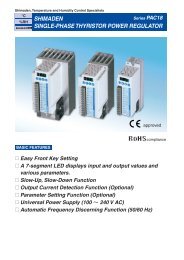
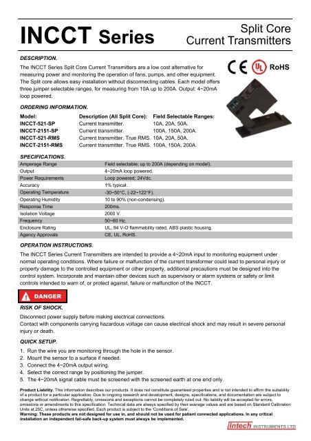
<strong>INCCT</strong> <strong>Series</strong><br />
Split Core<br />
Current <strong>Transmitters</strong><br />
DESCRIPTION.<br />
The <strong>INCCT</strong> <strong>Series</strong> Split Core Current <strong>Transmitters</strong> are a low cost alternative for<br />
measuring power and monitoring the operation of fans, pumps, and other equipment.<br />
The Split core allows easy installation without disconnecting cables. Each model offers<br />
three jumper selectable ranges, for measuring from 10A up to 200A. Output: 4~20mA<br />
loop powered.<br />
RoHS<br />
ORDERING INFORMATION.<br />
Model: Description (All Split Core): Field Selectable Ranges:<br />
<strong>INCCT</strong>-521-SP Current transmitter. 10A, 20A, 50A.<br />
<strong>INCCT</strong>-2151-SP Current transmitter. 100A, 150A, 200A.<br />
<strong>INCCT</strong>-521-RMS Current transmitter. True RMS. 10A, 20A, 50A.<br />
<strong>INCCT</strong>-2151-RMS Current transmitter. True RMS. 100A, 150A, 200A.<br />
SPECIFICATIONS.<br />
Amperage Range<br />
Field selectable; up to 200A (depending on model).<br />
Output<br />
4~20mA loop powered.<br />
Power Requirements<br />
Loop powered; 24Vdc.<br />
Accuracy<br />
1% typical.<br />
Operating Temperature<br />
-30~50C, (-22~122F).<br />
Operating Humidity<br />
10 to 90% (non-condensing).<br />
Response Time<br />
200ms.<br />
Isolation Voltage 2000 V.<br />
Frequency<br />
50~60 Hz.<br />
Enclosure Rating<br />
UL, 94 V-O flammability rated, ABS plastic housing.<br />
Agency Approvals<br />
CE, UL, RoHS.<br />
OPERATION INSTRUCTIONS.<br />
The <strong>INCCT</strong> <strong>Series</strong> Current <strong>Transmitters</strong> are intended to provide a 4~20mA input to monitoring equipment under<br />
normal operating conditions. Where failure or malfunction of the current transformer could lead to personal injury or<br />
property damage to the controlled equipment or other property, additional precautions must be designed into the<br />
control system. Incorporate and maintain other devices such as supervisory or alarm systems or safety or limit<br />
controls intended to warn of, or protect against, failure or malfunction of the <strong>INCCT</strong>.<br />
!<br />
DANGER<br />
RISK OF SHOCK.<br />
Disconnect power supply before making electrical connections.<br />
Contact with components carrying hazardous voltage can cause electrical shock and may result in severe personal<br />
injury or death.<br />
QUICK SETUP.<br />
1. Run the wire you are monitoring through the hole in the sensor.<br />
2. Mount the sensor to a surface if needed.<br />
3. Connect the 4~20mA output wiring.<br />
4. Select the correct range by positioning the jumper.<br />
5. The 4~20mA signal cable must be screened with the screened earth at one end only.<br />
Product Liability. This information describes our products. It does not constitute guaranteed properties and is not intended to affirm the suitability<br />
of a product for a particular application. Due to ongoing research and development, designs, specifications, and documentation are subject to<br />
change without notification. Regrettably, omissions and exceptions cannot be completely ruled out. No liability will be accepted for errors,<br />
omissions or amendments to this specification. Technical data are always specified by their average values and are based on Standard Calibration<br />
Units at 25C, unless otherwise specified. Each product is subject to the ‘Conditions of Sale’.<br />
Warning: These products are not designed for use in, and should not be used for patient connected applications. In any critical<br />
installation an independent fail-safe back-up system must always be implemented.
INSTALLATION.<br />
Press the tab toward the sensor to open.<br />
After placing the wire in the opening, press the hinged portion down firmly until a definite click is heard and the tab<br />
pops out fully.<br />
Sensor can be mounted using screw holes in any position or hung directly on wires with wire ties.<br />
NOTE: Keep split core sensors clean. Be careful not to allow grit or dirt to build up on contacts. Operation can be<br />
impaired if the mating surfaces do not have a connection. Always check visually, before closing.<br />
OUTPUT WIRING.<br />
Connect the 4~20mA control or monitoring wires to the sensor.<br />
Use 14 to 22 AWG copper wire.<br />
Tighten terminals securely.<br />
Be sure the output load or loop requirements are met.<br />
RANGE SELECTION.<br />
These models feature field selectable ranges:<br />
Determine the normal operating amperage of the monitored circuit.<br />
Select the range that is equal to or slightly higher than the normal operating amperage.<br />
Place the range jumper in the appropriate position according to selection:<br />
None:<br />
High<br />
Mid:<br />
High<br />
High:<br />
High<br />
10A or 100A<br />
Mid<br />
20A or 150A<br />
Mid<br />
50A or 200A<br />
Mid<br />
MAINTENANCE.<br />
Upon final installation of the <strong>INCCT</strong> Current Transmitter <strong>Series</strong>, no routine maintenance is required. A periodic check<br />
of system calibration is recommended. The <strong>INCCT</strong> <strong>Series</strong> are not field serviceable and should be returned if faulty<br />
(field repair should not be attempted and may void warranty).<br />
TROUBLESHOOTING.<br />
Problem<br />
Sensor has no output.<br />
Output signal is too low.<br />
Output signal is always at<br />
maximum.<br />
Sensor is always at 4mA.<br />
Output signal is always at<br />
20mA.<br />
Solution<br />
Polarity is not properly matched. Check and correct wiring polarity.<br />
Monitored load is not AC or is not on. Check that the monitored AC load is on.<br />
Check power supply current and voltage rating.<br />
The jumper may be set in a range that is too high for current being monitored. Move the jumper to<br />
the correct range.<br />
Monitored current is below minimal current required. Loop the monitored wire several times through<br />
the opening until the sensed current rises above the minimum. Sensed Amps = Actual Amps x<br />
Number of Loops. Count the loops on the inside of the opening.<br />
The load current is not sinusoidal.<br />
The jumper may be set in a range that is too low for current being monitored. Move jumper to the<br />
correct range.<br />
Monitored load is not AC or is not on. Check that the monitored AC load is on.<br />
The jumper may be set in a range that is too low for current being monitored. Move jumper to the<br />
correct range.<br />
www.intech.co.nz<br />
Christchurch Ph: +64 3 343 0646<br />
Auckland Ph: 09 827 1930<br />
Email: sales@intech.co.nz<br />
<strong>INCCT</strong> <strong>Series</strong> 091211