Download Installation Guide - Intech Instruments Ltd
Download Installation Guide - Intech Instruments Ltd
Download Installation Guide - Intech Instruments Ltd
- No tags were found...

Create successful ePaper yourself
Turn your PDF publications into a flip-book with our unique Google optimized e-Paper software.
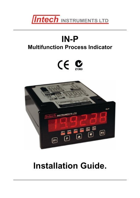
IN-PMultifunction Process Indicator<strong>Installation</strong> <strong>Guide</strong>.
IN-P <strong>Installation</strong> <strong>Guide</strong> Index.SECTION 1. – Description and Ordering Information. Page 3SECTION 2. – Specifications. Page 4SECTION 3. – Case Schematics. Page 4SECTION 4. – Input Jumper Configuration. Page 54.1 – Position your input Jumpers. Page 5SECTION 5. – Wiring. Page 65.1 – Connect your indicator to the power supply. Page 65.2 – Wire your IF11 analogue input module. Page 65.3 – Wire your analogue output (if fitted). Page 65.4 – Wire your relays (if fitted). Page 65.5 – Wire your serial port (if fitted). Page 65.6 – Wire your function pins (if required). Page 75.7 – Power up your indicator. Page 7SECTION 6. – Setup & Calibration. Page 76.1 – Enter PIN. Page 76.2 – Input setup. Page 76.3 – Calibration. Page 76.4 – Averaging. Page 86.5 – Analogue output setup. Page 86.6 – Serial setup. Page 96.7 – Edit calibration PIN. Page 9SECTION 7. – Setpoint Setup. Page 107.1 – Enter setpoint PIN. Page 107.2 – Edit setpoints. Page 107.3 – Edit setpoint PIN. Page 11SECTION 8. – Setpoint direct access. Page 11SECTION 9. – Reset PIN numbers. Page 11SECTION 10. – Display brightness. Page 11SECTION 11. – Display shortcuts. Page 112
IN-P(was IN-P4)Description.The IN-P Multifunction Process Indicator interfacessmoothly with a wide range of PLC and monitoringsystems. Designed specifically for use in processapplications this indicator accepts a variety of inputs.The IN-P can be configured for many different analogueinputs and functions as listed below.Setup and calibration is simple, with on-screen, step-bystepinstructions. The IN-P has a 6-digit LED display, 6set-points and 5 front panel buttons for easy setup andoperator interface. Up to 6 relay outputs, an analogueoutput and/or communications can also be added.Multifunction ProcessIndicatorOrdering Information.ITEMS CODE DESCRIPTIONSERIES IN-P- Multifunction Process IndicatorPRC1-1x 4~20mA / 0~10V input + 24Vdc excitationPRC4-4x 4~20mA input + 24Vdc excitation1x Thermocouple inputTC1-ANALOGUETypes B, J, K, N, R, S, TINPUTS4x Thermocouple inputTC4-Types B, J, K, N, R, S, TRTD1-1x RTD Pt100 inputRTD4-4x RTD Pt100 inputN- NoneRELAY OUTPUTSR2- 2x 5A relay outputsR4- 4x 5A relay outputsR6- 6x 5A relay outputsANALOGUE OUTPUT / RETRANSMISSIONN- NoneA- 1 x 4~20mA / 0~10V Analogue OutputN- NoneWS232-1x serial port Isolated RS232COMMUNICATIONSWS485-1x serial port Isolated RS485WEA-With an Ethernet port (Ascii)WEM-With an Ethernet port (Modbus)POWER SUPPLYHV- 85~265Vac / 95~370VdcLV- 15~48Vac / 10~72VdcOrdering Example: IN-P-RTD4-R2-N-WS485-HV Multifunction Process Indicator; 4x RTD Pt100 Inputs;2x 5A relay outputs; 1x serial port RS485;85~265Vac / 95~370Vdc Power Supply.Functions available on request.ABC*D*E*FG*HIJ- Auto or manual scanner with alarms.- Maths functions, (i) √, (ii) Difference, (iii) Average, (iv) Hi / Lo Select.- Hold, Tare, Reset (External switches connect to rear terminals).- Flow Rate + Totalising.- Energy display & totaliser (flow x ∆T).- Step controller.- Auto / Manual Station.- Retransmission.- Other Functions – please specify.- Data Logging.* Available on channel one only.Product Liability. This information describes our products. It does not constitute guaranteed properties and is not intended to affirm thesuitability of a product for a particular application. Due to ongoing research and development, designs, specifications, and documentation aresubject to change without notification. Regrettably, omissions and exceptions cannot be completely ruled out. No liability will be accepted forerrors, omissions or amendments to this specification. Technical data are always specified by their average values and are based onStandard Calibration Units at 25C, unless otherwise specified. Each product is subject to the ‘Conditions of Sale’.Warning: These products are not designed for use in, and should not be used for patient connected applications. In any criticalinstallation an independant fail-safe back-up system must always be implemented.3www.intech.co.nz
3.2 – Fig 2 - Rear viewCONNECTOR PINSG - Relays Wiring: Section 5.3H - Serial port Wiring: Section 5.5I - Analogue output Wiring: Section 5.4J – IP07 input module Jumper setup: Section 4.Wiring: Section 5.2K - Function pins Wiring: Section 5.6L - Power supply (HV/LV) Wiring: Section 5.1SECTION 4. – Input Jumper Configuration.Before you can begin wiring, the IP07 input module must be removed from the meter case so that the jumperscan be positioned for your input type. Remove the plastic backing plate from the rear of the meter by inserting ascrewdriver into the indents circled on the image below.Before you begin:Once the backing plate has been removed, gently slide the inputmodule from the case (see Section 3.2J to identify the input module).4.1 – Position your input jumpers.The IP07 input module has one jumper, which may need to be repositioned to suit your application. When youhave finished, slide the input module back into the case and replace the plastic backing plate.JUMPER POSITIONING20mA Current input (0~20mA or 4~20mA)Custom Custom input – call for options2V Voltage input (0~2V)10V Voltage input (0~10V)Example showing a Jumper In & Jumper OutJumper InJumper Out ( e.g. Jumper not fitted).5
SECTION 5. – Wiring.Before you begin:Determine whether your indicator is configured for low or high voltage power supply. Make sure to check thelabel on the unit against the colour of the power connector:Orange = High voltageBlack = Low voltage5.1 – Connect your indicator to the power supplyRefer to 3.2L.Wire your indicator to your power supply as per theappropriate diagram.High voltage (HV) -85~265Vac, 95~370VdcLow voltage (LV) -15~48Vac, 10~72VdcRemember to switch your powersupply off before you begin wiring,and NEVER connect your lowvoltage indicator to mains power.5.2 – Wire your IP07 analogue input moduleRefer to 3.2JMake sure that you have completed Section 4 before you begin wiring your input module. Once you haveadjusted your jumper settings as needed (see Section 4) and replaced the plastic backing plate, wire your inputmodule as shown in the appropriate diagram below.2-wire current or voltage process inputExternal excitation used3-wire current or voltage process inputIndicator supplied excitation2-wire current inputLoop powered sensor5.3 – Wire your relays (if fitted)Refer to 3.2GWire your relays as per the diagram. Relays can be programmed to operate within thetotal span range of the indicator. If you do not have any relays fitted, step 5.3 isskipped.5.4 – Wire your analogue output (if fitted)Refer to 3.2IIf your indicator has an analogue output fitted, wire it as shown.If you do not have an analogue output, step 5.4 is skipped.5.5 – Wire your serial port (if fitted)Refer to 3.2HIf your indicator has a serial port fitted, wire it as per the diagram. If you do not have a serialport fitted then step 5.5 is skipped.6
5.6 – Wire your function pins (if required)Refer to 3.2KConnect external switches to enable a function to be executed when its switch isactivated.ValleyHoldTestPeakClears the valley readingHold the current display valueReset the meterClears the peak reading5.7 – Power up your indicator.Once you have completed the wiring process it is safe to switch on your power supply. Ensure that yourdisplay is functioning before you proceed.SECTION 6. – Setup & Calibration.Enter the setup and calibration mode by pressing F1.6.1 – Enter PINA _ _ _ ENTER CAL PIN NUMBER scrolls across the display and toggles with 0. Use the and buttonsto enter your security code (factory default 1). Then press P. If the correct PIN is entered then the setup isstarted at 6.2.If an incorrect PIN number is entered, _ _ _ INCORRECT PIN NUMBER - ACCESS DENIED scrollsacross the display and it returns to the normal operating mode.You will be given the opportunity to change your PIN number at the end of this section (6.7). If youhave forgotten your PIN number, see Section 9.6.2 – Input setupInput defaults are set to 4~20mA, 50Hz, no decimal and no rounding.ABCDE_ _ _ INPUT SETUP scrolls across the display and toggles with SKIP. Press P to skip to 6.3, or the button and then P to ENTER input setup._ _ _ MAINS FREQUENCY scrolls across the display and toggles with the currently selected mainsfrequency. Using the and buttons, select either 50HZ or 60HZ. Then press P._ _ _ INPUT MODE scrolls across the display and toggles with the currently selected input mode. Usingthe and buttons, select: 4-20MA (4~20mA), 0-20MA (0~20mA), 2 V (0~2V) or 10 V (0~10V). Thenpress P.If you opt to change the input mode in this section then the jumper plug on the input module must also bechanged to match. See Section 4 for more information._ _ _ DECIMAL POINT POSITION scrolls across the display and toggles with the currently selecteddecimal point position. Use the and buttons to choose between: NO DP, 0.1, 0.12, 0.123, or 0.1234,and then press P._ _ _ DISPLAY ROUNDING scrolls across the display and toggles with the currently selected displayrounding. Using the and buttons, select: NONE, 2, 5 or 10. Then press P.Rounding is quoted in display counts and is not influenced by decimal point position. For example, if yourinput signal is 5.3mA, the display will show: 5.3 (for rounding=None), 5.4 (for rounding=2), 5.5 (forrounding=5) or 5.0 (for rounding=10).6.3 – Calibration.A_ _ _ CALIBRATION TECHNIQUE scrolls across the display and toggles with SKIP. Press P to skip to6.4, or use the and buttons to select either AUTO, MANUAL or S.G. (specific gravity), and thenpress P.AUTO - The automatic (key-in) 2-point calibration procedure uses zero and span values to calculate thescale and offset. This is the most accurate calibration method, but requires known low and high inputsignals (or the use of a calibrator).MANUAL - The manual calibration procedure uses low and high display values, and is intended for apre-calibrated sensor with a known output range. (For example 4mA=0 and 20mA=1000.) It does notrequire any input signals to be applied to the indicator during calibration.S.G. - The specific gravity calibration procedure allows the user to enter a scale factor which is used tocompensate for changes in the specific gravity of different substances. This does not constitute a fullcalibration and assumes that either an automatic or manual calibration has been applied previously withthe S.G. value set to 1.0.7
If you selected AUTO in 6.3A:B_ _ _ APPLY LOW INPUT SIGNAL – – – – ENTER LOW DISPLAY VALUE scrolls across the display.Apply the required low input signal to the indicator. Using the and buttons, enter your low end displayvalue. Then press P to accept._ _ _ APPLY HIGH INPUT SIGNAL – – – – ENTER HIGH DISPLAY VALUE scrolls across the display.Apply the required high input signal to the indicator. Using the and buttons, enter your high enddisplay value. Press P. If calibration is successful, the indicator will return to the operational display._ _ _ CALIBRATION FAILEDA calibration failure results when the indicator cannot detect any change in input signal during thecalibration procedure. After viewing this message you will be redirected to the operational display.Check your input signal and connections, and then repeat the process.If you selected MANUAL in 6.3A:C_ _ _ ENTER DISPLAY VALUE FOR (X) scrolls across. (X=0mA/4mA/0V, depending on your selection in6.2C.) Using the and buttons, enter your display value for the selected low input signal. Press P._ _ _ ENTER DISPLAY VALUE FOR (X) scrolls across. (X=20mA/2V/10V, depending on your selection in6.2C.) Using the and buttons, enter your display value for the selected high input signal. Then pressP to accept the new calibration values and return to the operational display.6.4 – Averaging.Your indicator has input signal averaging, guaranteeing stable measurement. If the input exceeds the averagingwindow value it will not average, ensuring fast response.A _ _ _ AVERAGING PARAMETERS scrolls across thedisplay and toggles with SKIP. Press P to skip to 6.5, orthe button and then P to ENTER averaging setup.B _ _ _ AVE SAMPLES scrolls across the display and toggleswith the currently selected averaging. Use the and buttons to alter the signal averaging and then press P.Increasing the number of samples will stabilisemeasurement, but it will also slow down response rates.C _ _ _ AVE WINDOW scrolls across the display and toggleswith the currently selected averaging window value. Usethe and buttons to alter the signal averaging window,and then press P.If your input signal contains large noise spikes then you can increase the size of averaging window toensure that these pulses are still averaged. However, increasing the averaging window too far will reducethe ability of the indicator to respond quickly to real changes in input signal. Setting the averaging windowto zero will turn off the window mode and give continuous averaging as per the selected averagingsamples.6.5 – Analogue output setup.If your indicator does not have this option installed then you will not view this section - setup will continue at 6.6.A _ _ _ ANALOG OUTPUT SETUP scrolls across display and toggles with SKIP. Press P to skip to 6.6, or the button and then P to ENTER analogue output setup.B _ _ _ LOW SCALE VALUE FOR ANALOG OUTPUT scrolls across the display and toggles with the currentselection. Use the and buttons to enter your cal low position, and then press P.This sets the display value for cal low (as at 6.5E).C _ _ _ HIGH SCALE VALUE FOR ANALOG OUTPUT scrolls across the display and toggles with the currentselection. Use the and buttons to enter your cal high position, and then press P.This sets the display value for cal high (as at 6.5F).D _ _ _ CALIBRATE ANALOG OUTPUT? scrolls across the display and toggles with SKIP. If you do notwish to calibrate your analogue output, press P now.If you would like to calibrate your analogue output:Set the analogue output board jumper in the correct position (see Section 4) and connect a mA or voltmeter across the analogue output connector (see 5.3). Press the button to select ENTER and then P toenter calibration mode.8
EF_ _ _ CAL LOW ANALOG OUTPUT scrolls across the display and toggles with a calibration number.Using the and buttons, calibrate your low analogue output as required. Then press P.The display value is shown in internal units (mA)._ _ _ CAL HIGH ANALOG OUTPUT scrolls across the display and toggles with a calibration number. Usingthe and buttons, calibrate your high analogue output as required. Then press P.The display value is shown in internal units (mA).6.6 – Serial setup.If your indicator does not have this option installed, then you will not view this section - setup will continue at 6.7.ABCDE_ _ _ SERIAL SETUP scrolls across the display and toggles with SKIP. Press P to skip to 6.7, or the button and then P to ENTER serial port setup._ _ _ SERIAL MODE scrolls across the display and toggles with the currently selected serial mode. Usingthe and buttons, select: ASCII, MODBUS (RTU) or RNGR A (Ranger A). Then press P.ASCII is a simple protocol that allows connection to various PC configuration tools. MODBUS is anindustry standard RTU slave mode that allows connection to a wide range of devices, such as PC’s orPLC’s. RNGR A is a continuous output, used to drive remote displays and other instruments in theRinstrum range. (Ranger is a trade name belonging to Rinstrum Pty <strong>Ltd</strong>.)_ _ _ BAUD RATE scrolls across the display and toggles with the current selection. Use the and buttons to select: 300, 600, 1200, 2400, 4800, 9600, 19200 or 38400. Then press P._ _ _ PARITY scrolls across the display and toggles with the current selection. Use the and buttons toselect: NONE, ODD or EVEN. Then press P._ _ _ SERIAL ADDRESS scrolls across the display and toggles with the current selection. Use the and buttons to set the serial address, and then press P.The serial address parameter is used to identify a particular device when it is used with other devices in asystem. (It applies particularly to Modbus mode when used on a RS485 network.) The serial address of theindicator must be set to match the serial address defined in the master device.RANGER A - This allows the indicator to drive a remote display from the Rinstrum range. The followingshows the output string format when Ranger A output is selected: STRING CHARACTER(S) STX character (ASCII 02) Output value sign (space for + and dash for -)Seven character ASCII string containing the current output value and decimal point.(If there is no decimal point, then the first character is a space. Leading zero blanking applies.)Single character output value status: U=Under, 0=Over, E=Error ETX character (ASCII 03)MODBUS REGISTERS - These are all holding registers and should be accessed via function codes 3 and6. Register addresses are displayed in the Modicon addressing format. i.e. Register 65=40065 (subtract 1for direct addressing).16-BIT40001 Alarm status (Bit 0=SP1, Bit1=SP2, Bit 2=SP3, Bit 3=SP4)40065 SP 1 hysteresis40071 SP 1 make delay40066 SP 2 hysteresis40072 SP 2 make delay40067 SP 3 hysteresis40073 SP 3 make delay40068 SP 4 hysteresis40074 SP 4 make delay32-BIT SIGNED (2x16-bit)40513 Process display40525 Peak40527 Valley40535 Setpoint 140537 Setpoint 240539 Setpoint 340541 Setpoint 440587 D/A scale low value40591 D/A scale high value6.7 – Edit calibration PIN.AB_ _ _ EDIT CAL PIN NUMBER scrolls across the display and toggles with SKIP. Press P to skip andreturn to the operational display, or the button and then P to ENTER._ _ _ ENTER NEW CAL PIN NUMBER scrolls across the display and toggles with the current PIN(default 1). Using the and buttons, enter your new calibration PIN number. Then press P to exit andreturn to the operational display.9
SECTION 7. – Setpoint Setup.ALARMThe setpoint value determines setpoint activation, andthe hysteresis value determines setpoint deactivation.CNTRL (Control)The setpoint value determines setpoint deactivation, andthe hysteresis value determines setpoint reactivation.Enter the setpoint setup mode by pressing and holding the F2 button for 3 seconds.7.1 – Enter setpoint PIN.A_ _ _ ENTER SP PIN NUMBER scrolls across the display and toggles with 0. Use the and buttons toenter your security code (factory default 1). Then press P. If the correct PIN is entered then the setup isstarted at 7.2.If an incorrect PIN number is entered, _ _ _ INCORRECT PIN NUMBER - ACCESS DENIED scrolls acrossthe display and it returns to the normal operating mode.You will be given the opportunity to change your PIN number at the end of this section (7.3). If you haveforgotten your PIN number, see Section 9.7.2 – Edit setpoints.ABCDEFG_ _ _ EDIT SETPOINT scrolls across the display and toggles with SKIP. Press P to skip to 7.4, or use the and buttons to select a setpoint to edit: SP 1, SP 2, SP 3 or SP 4. Then press P.SP3-4 are not available for models with only 2 relays installed._ _ _ SP VALUE scrolls across the display and toggles with the last setpoint value entered. Using the and buttons, adjust the display value at which the setpoint will activate. Then press P._ _ _ SP ACTIVATION scrolls across the display and toggles with the last selected setpoint activation. Usethe and buttons to select ABOVE or BELOW and then press P.ABOVE - relay turns on above the setpoint value and off below it.BELOW - relay turns on below the setpoint value and off above it._ _ _ SP TYPE scrolls across the display and toggles with the last selected setpoint type. Using the and buttons, select either ALARM or CNTRL (Control). Then press P._ _ _ HYSTERESIS VALUE scrolls across the display and toggles with the current selection. Use the and buttons to adjust this value if required. Press P.The hysteresis value defines the separation band between setpoint activation and deactivation. Hysteresiswill operate as per the specified type setting (see 7.2D)._ _ _ MAKE DELAY scrolls across the display and toggles with the current selection. Use the the and buttons to adjust this value if required. Press P. This value is displayed in seconds with a 0.1 secondresolution, and is the time delay before the relay energises._ _ _ OPEN ACCESS TO SP VALUE scrolls across the display and toggles with the last selected directaccess setting. Use the and buttons to select either YES or NO, and then press P.When enabled, this option allows the setpoint value to be edited directly after pressing the F2 button,without needing to enter a PIN number or go through all of the other options. Each setpoint can individuallyhave this option enabled or disabled.If you selected SP 1 in 7.2A:Skip 7.2H and continue to 7.2I now.HI_ _ _ TRAIL SP1 scrolls across the display and toggles with the current trailing setting. Using the and buttons, select either OFF or ON, and then press P.If you choose ON, the selected setpoint will become an offset value, which is effectively added to the valueof SP 1._ _ _ EDIT SETPOINT scrolls across the display and toggles with SKIP. You are now back at 7.2A. To editanother setpoint, follow the instructions from 7.2A-I. If you do not wish to edit another setpoint, press P nowto proceed to 7.3.10
7.3 – Edit setpoint PIN.A_ _ _ EDIT SP PIN NUMBER? scrolls across the display and toggles with SKIP. Press P to skip and returnto the operational display, or the button and then P to ENTER.B _ _ _ ENTER NEW SP PIN NUMBER scrolls across the display and toggles with the current PIN (default 1).Using the and buttons, enter your new totalizer reset and setpoint entry PIN number. Then press P toEXIT and return to the operational display.SECTION 8. – Setpoint direct access.If none of the setpoints have their direct access option enabled then the F2 button will not respond to a shortpress. (See 7.2G to enable.)8.1 – Setpoint direct accessABBegin by pressing the F2 button for half a second. The name of the first access-enabled setpoint (SP 1, SP2, SP 3 or SP 4) will appear on the display and toggle with the current value for that setpoint. Using the and buttons, adjust the selected value. Then press P to accept and progress to the next access-enabledsetpoint.SP3-4 are not available for models with only two relays installed.Pressing P for the last access-enabled setpoint will exit and return to the operational display.SECTION 9. – Reset PIN numbers.If you have forgotten either of your PIN numbers, follow the procedure below to reset both the calibration andsetpoint entry PIN’s to their factory default of 1.A Press , and P at the same time. (This key combination can be difficult to execute and you may needseveral tries to get it right.)B When successful, a factory identification text will scroll across the display, followed by: _ _ _ ALL PINNUMBERS RESET TO 1.C Reset the PIN numbers individually as required by following the instructions in Sections 6.7 and 7.3,entering ‘1’ whenever you are prompted for your current PIN.SECTION 10. – Display brightness.To adjust the brightness of the LED display:ABPress the P and buttons together from the operational display. BRI appears on the screen and toggleswith the current brightness setting.Use the and buttons to adjust the brightness of the LED backlight as required, and then press P. Thedisplay returns to normal operating mode.SECTION 11. – Display Shortcuts.Use these shortcuts for quick viewing of specified parameters from the operational display:To view the maximum (peak) value: Press the button for ½ a second. The word PEAK appears on thedisplay and toggles with the maximum measured process input value.Press P to return to the operational display.To view the minimum (valley) value: Press the button for ½ a second. The word VALLEY appears on thedisplay and toggles with the minimum measured process input value.Press P to return to the operational display.To reset peak or valley:Press both the and buttons together while the required parameteris being displayed.11
12www.intech.co.nzChristchurch Ph: +64 3 343 0646Auckland Ph: 09 827 1930Email: sales@intech.co.nzIN-P 160910